

REMEHA Gas 220 Ace 220, Gas 220 Ace Series, Gas 220 Ace 160, Gas 220 Ace 250, Gas 220 Ace 300 Installation, User And Service Manual

United Kingdom
en
Installation, User and Service Manual
High-efficiency floor-standing gas boiler
Gas 220 Ace
160 - 200 - 250 - 300
HMI S-control

Dear Customer,
Thank you very much for buying this appliance.
Please read through the manual carefully before using the product, and keep it in a safe place for later reference. In order to
ensure continued safe and efficient operation we recommend that the product is serviced regularly. Our service and customer
service organisation can assist with this.
We hope you enjoy years of problem-free operation with the product.

Contents
7665063 - v.05 - 18102018 3
Contents
1 Safety . . . . . . . . . . . . . . . . . . . . . . . . . . . . . . . . . . . . . . . . . . . . . . . . . . . . . . . . . . . . . . . . . . . . . . . . . . . . . . . . . . . . . . . . . . . . 6
1.1 General safety instructions . . . . . . . . . . . . . . . . . . . . . . . . . . . . . . . . . . . . . . . . . . . . . . . . . . . . . . . . . . . . . . . . . . . . . . . 6
1.2 Recommendations . . . . . . . . . . . . . . . . . . . . . . . . . . . . . . . . . . . . . . . . . . . . . . . . . . . . . . . . . . . . . . . . . . . . . . . . . . . . . 8
1.3 Specific safety instructions . . . . . . . . . . . . . . . . . . . . . . . . . . . . . . . . . . . . . . . . . . . . . . . . . . . . . . . . . . . . . . . . . . . . . . 10
1.3.1 Additional guidelines . . . . . . . . . . . . . . . . . . . . . . . . . . . . . . . . . . . . . . . . . . . . . . . . . . . . . . . . . . . . . . . . . . . 10
1.4 Liabilities . . . . . . . . . . . . . . . . . . . . . . . . . . . . . . . . . . . . . . . . . . . . . . . . . . . . . . . . . . . . . . . . . . . . . . . . . . . . . . . . . . . . 10
1.4.1 Manufacturer's liability . . . . . . . . . . . . . . . . . . . . . . . . . . . . . . . . . . . . . . . . . . . . . . . . . . . . . . . . . . . . . . . . . . 10
1.4.2 Installer's liability . . . . . . . . . . . . . . . . . . . . . . . . . . . . . . . . . . . . . . . . . . . . . . . . . . . . . . . . . . . . . . . . . . . . . . 10
1.4.3 User's liability . . . . . . . . . . . . . . . . . . . . . . . . . . . . . . . . . . . . . . . . . . . . . . . . . . . . . . . . . . . . . . . . . . . . . . . . .11
2 About this manual . . . . . . . . . . . . . . . . . . . . . . . . . . . . . . . . . . . . . . . . . . . . . . . . . . . . . . . . . . . . . . . . . . . . . . . . . . . . . . . . . . 12
2.1 General . . . . . . . . . . . . . . . . . . . . . . . . . . . . . . . . . . . . . . . . . . . . . . . . . . . . . . . . . . . . . . . . . . . . . . . . . . . . . . . . . . . . . 12
2.2 Additional documentation . . . . . . . . . . . . . . . . . . . . . . . . . . . . . . . . . . . . . . . . . . . . . . . . . . . . . . . . . . . . . . . . . . . . . . . 12
2.3 Symbols used in the manual . . . . . . . . . . . . . . . . . . . . . . . . . . . . . . . . . . . . . . . . . . . . . . . . . . . . . . . . . . . . . . . . . . . . .12
3 Technical specifications . . . . . . . . . . . . . . . . . . . . . . . . . . . . . . . . . . . . . . . . . . . . . . . . . . . . . . . . . . . . . . . . . . . . . . . . . . . . . 13
3.1 Homologations . . . . . . . . . . . . . . . . . . . . . . . . . . . . . . . . . . . . . . . . . . . . . . . . . . . . . . . . . . . . . . . . . . . . . . . . . . . . . . . 13
3.1.1 Certifications . . . . . . . . . . . . . . . . . . . . . . . . . . . . . . . . . . . . . . . . . . . . . . . . . . . . . . . . . . . . . . . . . . . . . . . . . 13
3.1.2 Unit categories . . . . . . . . . . . . . . . . . . . . . . . . . . . . . . . . . . . . . . . . . . . . . . . . . . . . . . . . . . . . . . . . . . . . . . . .13
3.1.3 Factory test . . . . . . . . . . . . . . . . . . . . . . . . . . . . . . . . . . . . . . . . . . . . . . . . . . . . . . . . . . . . . . . . . . . . . . . . . . 13
3.2 Technical data . . . . . . . . . . . . . . . . . . . . . . . . . . . . . . . . . . . . . . . . . . . . . . . . . . . . . . . . . . . . . . . . . . . . . . . . . . . . . . . .13
3.3 Dimensions and connections . . . . . . . . . . . . . . . . . . . . . . . . . . . . . . . . . . . . . . . . . . . . . . . . . . . . . . . . . . . . . . . . . . . . 16
3.4 Electrical diagram . . . . . . . . . . . . . . . . . . . . . . . . . . . . . . . . . . . . . . . . . . . . . . . . . . . . . . . . . . . . . . . . . . . . . . . . . . . . . 17
4 Description of the product . . . . . . . . . . . . . . . . . . . . . . . . . . . . . . . . . . . . . . . . . . . . . . . . . . . . . . . . . . . . . . . . . . . . . . . . . . . . 18
4.1 Operating principle . . . . . . . . . . . . . . . . . . . . . . . . . . . . . . . . . . . . . . . . . . . . . . . . . . . . . . . . . . . . . . . . . . . . . . . . . . . . 18
4.1.1 Gas/air regulation . . . . . . . . . . . . . . . . . . . . . . . . . . . . . . . . . . . . . . . . . . . . . . . . . . . . . . . . . . . . . . . . . . . . . 18
4.1.2 Combustion . . . . . . . . . . . . . . . . . . . . . . . . . . . . . . . . . . . . . . . . . . . . . . . . . . . . . . . . . . . . . . . . . . . . . . . . . . 18
4.1.3 Control system . . . . . . . . . . . . . . . . . . . . . . . . . . . . . . . . . . . . . . . . . . . . . . . . . . . . . . . . . . . . . . . . . . . . . . . .18
4.1.4 Control . . . . . . . . . . . . . . . . . . . . . . . . . . . . . . . . . . . . . . . . . . . . . . . . . . . . . . . . . . . . . . . . . . . . . . . . . . . . . . 18
4.1.5 Regulating the water temperature . . . . . . . . . . . . . . . . . . . . . . . . . . . . . . . . . . . . . . . . . . . . . . . . . . . . . . . . . 19
4.1.6 Protection against shortage of water . . . . . . . . . . . . . . . . . . . . . . . . . . . . . . . . . . . . . . . . . . . . . . . . . . . . . . . 19
4.1.7 Water flow . . . . . . . . . . . . . . . . . . . . . . . . . . . . . . . . . . . . . . . . . . . . . . . . . . . . . . . . . . . . . . . . . . . . . . . . . . . 19
4.1.8 Hydraulic pressure sensor . . . . . . . . . . . . . . . . . . . . . . . . . . . . . . . . . . . . . . . . . . . . . . . . . . . . . . . . . . . . . . .19
4.1.9 Air pressure differential switch . . . . . . . . . . . . . . . . . . . . . . . . . . . . . . . . . . . . . . . . . . . . . . . . . . . . . . . . . . . .19
4.1.10 Circulating pump . . . . . . . . . . . . . . . . . . . . . . . . . . . . . . . . . . . . . . . . . . . . . . . . . . . . . . . . . . . . . . . . . . . . . . 19
4.1.11 Calorifier connection . . . . . . . . . . . . . . . . . . . . . . . . . . . . . . . . . . . . . . . . . . . . . . . . . . . . . . . . . . . . . . . . . . . 20
4.2 Main components . . . . . . . . . . . . . . . . . . . . . . . . . . . . . . . . . . . . . . . . . . . . . . . . . . . . . . . . . . . . . . . . . . . . . . . . . . . . . 20
4.3 Control panel description . . . . . . . . . . . . . . . . . . . . . . . . . . . . . . . . . . . . . . . . . . . . . . . . . . . . . . . . . . . . . . . . . . . . . . . 21
4.3.1 What each key means . . . . . . . . . . . . . . . . . . . . . . . . . . . . . . . . . . . . . . . . . . . . . . . . . . . . . . . . . . . . . . . . . . 21
4.3.2 Meaning of the symbols on the display . . . . . . . . . . . . . . . . . . . . . . . . . . . . . . . . . . . . . . . . . . . . . . . . . . . . . 21
4.3.3 Browsing in the menus . . . . . . . . . . . . . . . . . . . . . . . . . . . . . . . . . . . . . . . . . . . . . . . . . . . . . . . . . . . . . . . . . 22
4.4 Standard delivery . . . . . . . . . . . . . . . . . . . . . . . . . . . . . . . . . . . . . . . . . . . . . . . . . . . . . . . . . . . . . . . . . . . . . . . . . . . . . 23
4.5 Accessories and options . . . . . . . . . . . . . . . . . . . . . . . . . . . . . . . . . . . . . . . . . . . . . . . . . . . . . . . . . . . . . . . . . . . . . . . . 23
5 Before installation . . . . . . . . . . . . . . . . . . . . . . . . . . . . . . . . . . . . . . . . . . . . . . . . . . . . . . . . . . . . . . . . . . . . . . . . . . . . . . . . . . 24
5.1 Installation regulations . . . . . . . . . . . . . . . . . . . . . . . . . . . . . . . . . . . . . . . . . . . . . . . . . . . . . . . . . . . . . . . . . . . . . . . . . 24
5.2 Choice of the location . . . . . . . . . . . . . . . . . . . . . . . . . . . . . . . . . . . . . . . . . . . . . . . . . . . . . . . . . . . . . . . . . . . . . . . . . . 24
5.2.1 Data plate . . . . . . . . . . . . . . . . . . . . . . . . . . . . . . . . . . . . . . . . . . . . . . . . . . . . . . . . . . . . . . . . . . . . . . . . . . . 24
5.2.2 Location of the boiler . . . . . . . . . . . . . . . . . . . . . . . . . . . . . . . . . . . . . . . . . . . . . . . . . . . . . . . . . . . . . . . . . . . 24
5.3 Transport . . . . . . . . . . . . . . . . . . . . . . . . . . . . . . . . . . . . . . . . . . . . . . . . . . . . . . . . . . . . . . . . . . . . . . . . . . . . . . . . . . . .25
5.4 Unpacking & initial preparation . . . . . . . . . . . . . . . . . . . . . . . . . . . . . . . . . . . . . . . . . . . . . . . . . . . . . . . . . . . . . . . . . . . 26
6 Installation . . . . . . . . . . . . . . . . . . . . . . . . . . . . . . . . . . . . . . . . . . . . . . . . . . . . . . . . . . . . . . . . . . . . . . . . . . . . . . . . . . . . . . . . 27
6.1 General . . . . . . . . . . . . . . . . . . . . . . . . . . . . . . . . . . . . . . . . . . . . . . . . . . . . . . . . . . . . . . . . . . . . . . . . . . . . . . . . . . . . . 27
6.2 Preparation . . . . . . . . . . . . . . . . . . . . . . . . . . . . . . . . . . . . . . . . . . . . . . . . . . . . . . . . . . . . . . . . . . . . . . . . . . . . . . . . . . 27
6.2.1 Positioning the boiler . . . . . . . . . . . . . . . . . . . . . . . . . . . . . . . . . . . . . . . . . . . . . . . . . . . . . . . . . . . . . . . . . . . 27
6.3 Hydraulic connections . . . . . . . . . . . . . . . . . . . . . . . . . . . . . . . . . . . . . . . . . . . . . . . . . . . . . . . . . . . . . . . . . . . . . . . . . .27
6.3.1 Rinsing the system . . . . . . . . . . . . . . . . . . . . . . . . . . . . . . . . . . . . . . . . . . . . . . . . . . . . . . . . . . . . . . . . . . . . 27
6.3.2 Connecting the heating circuit . . . . . . . . . . . . . . . . . . . . . . . . . . . . . . . . . . . . . . . . . . . . . . . . . . . . . . . . . . . . 28
6.3.3 Connecting the condensate drain pipe . . . . . . . . . . . . . . . . . . . . . . . . . . . . . . . . . . . . . . . . . . . . . . . . . . . . . 29
6.4 Gas connection . . . . . . . . . . . . . . . . . . . . . . . . . . . . . . . . . . . . . . . . . . . . . . . . . . . . . . . . . . . . . . . . . . . . . . . . . . . . . . . 29
6.5 Air supply/flue gas outlet connections . . . . . . . . . . . . . . . . . . . . . . . . . . . . . . . . . . . . . . . . . . . . . . . . . . . . . . . . . . . . . .30
6.5.1 Classification . . . . . . . . . . . . . . . . . . . . . . . . . . . . . . . . . . . . . . . . . . . . . . . . . . . . . . . . . . . . . . . . . . . . . . . . . 30

Contents
4 7665063 - v.05 - 18102018
6.5.2 Material . . . . . . . . . . . . . . . . . . . . . . . . . . . . . . . . . . . . . . . . . . . . . . . . . . . . . . . . . . . . . . . . . . . . . . . . . . . . . 32
6.5.3 Dimensions of flue gas outlet pipe . . . . . . . . . . . . . . . . . . . . . . . . . . . . . . . . . . . . . . . . . . . . . . . . . . . . . . . . .33
6.5.4 Length of the air and flue gas pipes . . . . . . . . . . . . . . . . . . . . . . . . . . . . . . . . . . . . . . . . . . . . . . . . . . . . . . . .33
6.5.5 Additional guidelines . . . . . . . . . . . . . . . . . . . . . . . . . . . . . . . . . . . . . . . . . . . . . . . . . . . . . . . . . . . . . . . . . . . 35
6.5.6 Connecting the flue gas outlet . . . . . . . . . . . . . . . . . . . . . . . . . . . . . . . . . . . . . . . . . . . . . . . . . . . . . . . . . . . . 36
6.5.7 Connecting the air supply . . . . . . . . . . . . . . . . . . . . . . . . . . . . . . . . . . . . . . . . . . . . . . . . . . . . . . . . . . . . . . . 36
6.5.8 Specific air and flue gas applications . . . . . . . . . . . . . . . . . . . . . . . . . . . . . . . . . . . . . . . . . . . . . . . . . . . . . . .37
6.6 Electrical connections . . . . . . . . . . . . . . . . . . . . . . . . . . . . . . . . . . . . . . . . . . . . . . . . . . . . . . . . . . . . . . . . . . . . . . . . . . 37
6.6.1 Recommendations . . . . . . . . . . . . . . . . . . . . . . . . . . . . . . . . . . . . . . . . . . . . . . . . . . . . . . . . . . . . . . . . . . . . .37
6.6.2 Control unit . . . . . . . . . . . . . . . . . . . . . . . . . . . . . . . . . . . . . . . . . . . . . . . . . . . . . . . . . . . . . . . . . . . . . . . . . . 37
6.6.3 Assembly of the control panel . . . . . . . . . . . . . . . . . . . . . . . . . . . . . . . . . . . . . . . . . . . . . . . . . . . . . . . . . . . . 38
6.6.4 Installation of the connection box . . . . . . . . . . . . . . . . . . . . . . . . . . . . . . . . . . . . . . . . . . . . . . . . . . . . . . . . . 39
6.6.5 Connection options for the standard PCB . . . . . . . . . . . . . . . . . . . . . . . . . . . . . . . . . . . . . . . . . . . . . . . . . . . 40
6.7 Filling the installation . . . . . . . . . . . . . . . . . . . . . . . . . . . . . . . . . . . . . . . . . . . . . . . . . . . . . . . . . . . . . . . . . . . . . . . . . . .43
6.7.1 Water treatment . . . . . . . . . . . . . . . . . . . . . . . . . . . . . . . . . . . . . . . . . . . . . . . . . . . . . . . . . . . . . . . . . . . . . . .43
6.7.2 Filling the siphon . . . . . . . . . . . . . . . . . . . . . . . . . . . . . . . . . . . . . . . . . . . . . . . . . . . . . . . . . . . . . . . . . . . . . . 43
6.7.3 Filling the system . . . . . . . . . . . . . . . . . . . . . . . . . . . . . . . . . . . . . . . . . . . . . . . . . . . . . . . . . . . . . . . . . . . . . .44
7 Commissioning . . . . . . . . . . . . . . . . . . . . . . . . . . . . . . . . . . . . . . . . . . . . . . . . . . . . . . . . . . . . . . . . . . . . . . . . . . . . . . . . . . . . 45
7.1 Checklist before commissioning . . . . . . . . . . . . . . . . . . . . . . . . . . . . . . . . . . . . . . . . . . . . . . . . . . . . . . . . . . . . . . . . . . 45
7.1.1 Preparing the boiler for commissioning . . . . . . . . . . . . . . . . . . . . . . . . . . . . . . . . . . . . . . . . . . . . . . . . . . . . . 45
7.1.2 Gas circuit . . . . . . . . . . . . . . . . . . . . . . . . . . . . . . . . . . . . . . . . . . . . . . . . . . . . . . . . . . . . . . . . . . . . . . . . . . . 45
7.1.3 Hydraulic circuit . . . . . . . . . . . . . . . . . . . . . . . . . . . . . . . . . . . . . . . . . . . . . . . . . . . . . . . . . . . . . . . . . . . . . . . 45
7.1.4 Electrical connections . . . . . . . . . . . . . . . . . . . . . . . . . . . . . . . . . . . . . . . . . . . . . . . . . . . . . . . . . . . . . . . . . . 45
7.2 Commissioning procedure . . . . . . . . . . . . . . . . . . . . . . . . . . . . . . . . . . . . . . . . . . . . . . . . . . . . . . . . . . . . . . . . . . . . . . 45
7.3 Gas settings . . . . . . . . . . . . . . . . . . . . . . . . . . . . . . . . . . . . . . . . . . . . . . . . . . . . . . . . . . . . . . . . . . . . . . . . . . . . . . . . . 46
7.3.1 Adjusting to a different gas type . . . . . . . . . . . . . . . . . . . . . . . . . . . . . . . . . . . . . . . . . . . . . . . . . . . . . . . . . . 46
7.3.2 Checking/setting combustion . . . . . . . . . . . . . . . . . . . . . . . . . . . . . . . . . . . . . . . . . . . . . . . . . . . . . . . . . . . . .47
7.4 Final instructions . . . . . . . . . . . . . . . . . . . . . . . . . . . . . . . . . . . . . . . . . . . . . . . . . . . . . . . . . . . . . . . . . . . . . . . . . . . . . . 50
8 Operation . . . . . . . . . . . . . . . . . . . . . . . . . . . . . . . . . . . . . . . . . . . . . . . . . . . . . . . . . . . . . . . . . . . . . . . . . . . . . . . . . . . . . . . . .51
8.1 Use of the control panel . . . . . . . . . . . . . . . . . . . . . . . . . . . . . . . . . . . . . . . . . . . . . . . . . . . . . . . . . . . . . . . . . . . . . . . . 51
8.2 Shutdown . . . . . . . . . . . . . . . . . . . . . . . . . . . . . . . . . . . . . . . . . . . . . . . . . . . . . . . . . . . . . . . . . . . . . . . . . . . . . . . . . . . 51
8.3 Frost protection . . . . . . . . . . . . . . . . . . . . . . . . . . . . . . . . . . . . . . . . . . . . . . . . . . . . . . . . . . . . . . . . . . . . . . . . . . . . . . . 51
9 Settings . . . . . . . . . . . . . . . . . . . . . . . . . . . . . . . . . . . . . . . . . . . . . . . . . . . . . . . . . . . . . . . . . . . . . . . . . . . . . . . . . . . . . . . . . . 52
9.1 List of parameters . . . . . . . . . . . . . . . . . . . . . . . . . . . . . . . . . . . . . . . . . . . . . . . . . . . . . . . . . . . . . . . . . . . . . . . . . . . . . 52
9.1.1 Parameters - FSB-WHB-HE-150-300 . . . . . . . . . . . . . . . . . . . . . . . . . . . . . . . . . . . . . . . . . . . . . . . . . . . . . . 52
9.2 Changing the parameters . . . . . . . . . . . . . . . . . . . . . . . . . . . . . . . . . . . . . . . . . . . . . . . . . . . . . . . . . . . . . . . . . . . . . . . 55
9.2.1 Configuring the installation parameters . . . . . . . . . . . . . . . . . . . . . . . . . . . . . . . . . . . . . . . . . . . . . . . . . . . . . 55
9.3 Reading out measured values . . . . . . . . . . . . . . . . . . . . . . . . . . . . . . . . . . . . . . . . . . . . . . . . . . . . . . . . . . . . . . . . . . . 56
9.3.1 Reading out counters . . . . . . . . . . . . . . . . . . . . . . . . . . . . . . . . . . . . . . . . . . . . . . . . . . . . . . . . . . . . . . . . . . .56
9.3.2 Reading out signals and software versions . . . . . . . . . . . . . . . . . . . . . . . . . . . . . . . . . . . . . . . . . . . . . . . . . . 57
9.3.3 Counters - FSB-WHB-HE-150-300 . . . . . . . . . . . . . . . . . . . . . . . . . . . . . . . . . . . . . . . . . . . . . . . . . . . . . . . . 58
9.3.4 Signals - FSB-WHB-HE-150-300 . . . . . . . . . . . . . . . . . . . . . . . . . . . . . . . . . . . . . . . . . . . . . . . . . . . . . . . . . 58
9.3.5 Status and sub-status - FSB-WHB-HE-150-300 . . . . . . . . . . . . . . . . . . . . . . . . . . . . . . . . . . . . . . . . . . . . . . 59
10 Maintenance . . . . . . . . . . . . . . . . . . . . . . . . . . . . . . . . . . . . . . . . . . . . . . . . . . . . . . . . . . . . . . . . . . . . . . . . . . . . . . . . . . . . . . 62
10.1 General . . . . . . . . . . . . . . . . . . . . . . . . . . . . . . . . . . . . . . . . . . . . . . . . . . . . . . . . . . . . . . . . . . . . . . . . . . . . . . . . . . . . . 62
10.2 Maintenance message . . . . . . . . . . . . . . . . . . . . . . . . . . . . . . . . . . . . . . . . . . . . . . . . . . . . . . . . . . . . . . . . . . . . . . . . . 62
10.2.1 Resetting the service messages . . . . . . . . . . . . . . . . . . . . . . . . . . . . . . . . . . . . . . . . . . . . . . . . . . . . . . . . . . 62
10.2.2 Starting a new service interval . . . . . . . . . . . . . . . . . . . . . . . . . . . . . . . . . . . . . . . . . . . . . . . . . . . . . . . . . . . .63
10.3 Standard inspection and maintenance operations . . . . . . . . . . . . . . . . . . . . . . . . . . . . . . . . . . . . . . . . . . . . . . . . . . . . 63
10.3.1 Checking the water pressure . . . . . . . . . . . . . . . . . . . . . . . . . . . . . . . . . . . . . . . . . . . . . . . . . . . . . . . . . . . . . 63
10.3.2 Checking the water quality . . . . . . . . . . . . . . . . . . . . . . . . . . . . . . . . . . . . . . . . . . . . . . . . . . . . . . . . . . . . . . .63
10.3.3 Checking the ionisation current . . . . . . . . . . . . . . . . . . . . . . . . . . . . . . . . . . . . . . . . . . . . . . . . . . . . . . . . . . . 63
10.3.4 Check the flue gas outlet/air supply connections . . . . . . . . . . . . . . . . . . . . . . . . . . . . . . . . . . . . . . . . . . . . . .64
10.3.5 Checking the combustion . . . . . . . . . . . . . . . . . . . . . . . . . . . . . . . . . . . . . . . . . . . . . . . . . . . . . . . . . . . . . . . 64
10.3.6 Checking the PS air pressure differential switch . . . . . . . . . . . . . . . . . . . . . . . . . . . . . . . . . . . . . . . . . . . . . . 64
10.3.7 Checking the VPS gas leakage control . . . . . . . . . . . . . . . . . . . . . . . . . . . . . . . . . . . . . . . . . . . . . . . . . . . . . 66
10.3.8 Checking the minimum gas pressure switch GPS . . . . . . . . . . . . . . . . . . . . . . . . . . . . . . . . . . . . . . . . . . . . .68
10.3.9 Checking the burner and cleaning the heat exchanger . . . . . . . . . . . . . . . . . . . . . . . . . . . . . . . . . . . . . . . . . 69
10.3.10 Clean the condensate collector . . . . . . . . . . . . . . . . . . . . . . . . . . . . . . . . . . . . . . . . . . . . . . . . . . . . . . . . . . . 70
10.3.11 Cleaning the siphon . . . . . . . . . . . . . . . . . . . . . . . . . . . . . . . . . . . . . . . . . . . . . . . . . . . . . . . . . . . . . . . . . . . . 70
10.4 Specific maintenance work . . . . . . . . . . . . . . . . . . . . . . . . . . . . . . . . . . . . . . . . . . . . . . . . . . . . . . . . . . . . . . . . . . . . . . 70
10.4.1 Replacing the ionisation/ignition electrode . . . . . . . . . . . . . . . . . . . . . . . . . . . . . . . . . . . . . . . . . . . . . . . . . . 71

Contents
7665063 - v.05 - 18102018 5
10.4.2 Checking the non-return valve . . . . . . . . . . . . . . . . . . . . . . . . . . . . . . . . . . . . . . . . . . . . . . . . . . . . . . . . . . . .71
10.4.3 Reassembling the boiler . . . . . . . . . . . . . . . . . . . . . . . . . . . . . . . . . . . . . . . . . . . . . . . . . . . . . . . . . . . . . . . . 72
10.5 Disposal . . . . . . . . . . . . . . . . . . . . . . . . . . . . . . . . . . . . . . . . . . . . . . . . . . . . . . . . . . . . . . . . . . . . . . . . . . . . . . . . . . . . 73
10.5.1 Removal/recycling . . . . . . . . . . . . . . . . . . . . . . . . . . . . . . . . . . . . . . . . . . . . . . . . . . . . . . . . . . . . . . . . . . . . . 73
11 Troubleshooting . . . . . . . . . . . . . . . . . . . . . . . . . . . . . . . . . . . . . . . . . . . . . . . . . . . . . . . . . . . . . . . . . . . . . . . . . . . . . . . . . . . .74
11.1 Error codes . . . . . . . . . . . . . . . . . . . . . . . . . . . . . . . . . . . . . . . . . . . . . . . . . . . . . . . . . . . . . . . . . . . . . . . . . . . . . . . . . . 74
11.1.1 Warning - FSB-WHB-HE-150-300 . . . . . . . . . . . . . . . . . . . . . . . . . . . . . . . . . . . . . . . . . . . . . . . . . . . . . . . . . 74
11.1.2 Blocking - FSB-WHB-HE-150-300 . . . . . . . . . . . . . . . . . . . . . . . . . . . . . . . . . . . . . . . . . . . . . . . . . . . . . . . . .75
11.1.3 Lock-out - FSB-WHB-HE-150-300 . . . . . . . . . . . . . . . . . . . . . . . . . . . . . . . . . . . . . . . . . . . . . . . . . . . . . . . . .77
11.2 Error memory . . . . . . . . . . . . . . . . . . . . . . . . . . . . . . . . . . . . . . . . . . . . . . . . . . . . . . . . . . . . . . . . . . . . . . . . . . . . . . . . 80
12 Removal/recycling . . . . . . . . . . . . . . . . . . . . . . . . . . . . . . . . . . . . . . . . . . . . . . . . . . . . . . . . . . . . . . . . . . . . . . . . . . . . . . . . . . 81
13 Spare parts . . . . . . . . . . . . . . . . . . . . . . . . . . . . . . . . . . . . . . . . . . . . . . . . . . . . . . . . . . . . . . . . . . . . . . . . . . . . . . . . . . . . . . . 82
13.1 General . . . . . . . . . . . . . . . . . . . . . . . . . . . . . . . . . . . . . . . . . . . . . . . . . . . . . . . . . . . . . . . . . . . . . . . . . . . . . . . . . . . . . 82
13.2 Parts . . . . . . . . . . . . . . . . . . . . . . . . . . . . . . . . . . . . . . . . . . . . . . . . . . . . . . . . . . . . . . . . . . . . . . . . . . . . . . . . . . . . . . . 83
14 Appendix . . . . . . . . . . . . . . . . . . . . . . . . . . . . . . . . . . . . . . . . . . . . . . . . . . . . . . . . . . . . . . . . . . . . . . . . . . . . . . . . . . . . . . . . . 85
14.1 ErP information . . . . . . . . . . . . . . . . . . . . . . . . . . . . . . . . . . . . . . . . . . . . . . . . . . . . . . . . . . . . . . . . . . . . . . . . . . . . . . . 85
14.1.1 Product fiche . . . . . . . . . . . . . . . . . . . . . . . . . . . . . . . . . . . . . . . . . . . . . . . . . . . . . . . . . . . . . . . . . . . . . . . . . 85
14.2 EC Declaration of Conformity . . . . . . . . . . . . . . . . . . . . . . . . . . . . . . . . . . . . . . . . . . . . . . . . . . . . . . . . . . . . . . . . . . . . 85
14.3 Checklist for commissioning . . . . . . . . . . . . . . . . . . . . . . . . . . . . . . . . . . . . . . . . . . . . . . . . . . . . . . . . . . . . . . . . . . . . . 86
14.4 Checklist for annual maintenance . . . . . . . . . . . . . . . . . . . . . . . . . . . . . . . . . . . . . . . . . . . . . . . . . . . . . . . . . . . . . . . . .87
1 Safety
6 7665063 - v.05 - 18102018
1 Safety
1.1 General safety instructions
For the installer:
Danger
If you smell gas:
1. Do not use naked flames, do not smoke and
do not operate electrical contacts or switches
(doorbell, lighting, motor, lift etc).
2. Shut off the gas supply.
3. Open the windows.
4. Trace possible leaks and seal them off
immediately.
5. If the leak is upstream of the gas meter, notify
the gas company.
Danger
If you smell flue gases:
1. Switch the boiler off.
2. Open the windows.
3. Trace possible leaks and seal them off
immediately.
Caution
After maintenance or repair work, check the
entire heating installation to ensure that there are
no leaks.
For the end user:

1 Safety
7665063 - v.05 - 18102018 7
Danger
If you smell gas:
1. Do not use naked flames, do not smoke and
do not operate electrical contacts or switches
(doorbell, lighting, motor, lift etc).
2. Shut off the gas supply.
3. Open the windows.
4. Report any leaks immediately.
5. Evacuate the property.
6. Contact a qualified installer.
Danger
If you smell flue gases:
1. Switch the boiler off.
2. Open the windows.
3. Report any leaks immediately.
4. Evacuate the property.
5. Contact a qualified installer.
Warning
Do not touch the flue gas pipes. Depending on
the boiler settings, the temperature of the flue gas
pipes can rise to over 60°C.
Warning
Do not touch radiators for long periods.
Depending on the boiler settings, the temperature
of the radiators can rise to over 60°C.
Warning
Be careful when using the domestic hot water.
Depending on the boiler settings, the temperature
of domestic hot water can rise to over 65°C.
Warning
The use of the boiler and the installation by you
as the end-user must be limited to the operations
described in this manual. All other actions may
only be undertaken by a qualified fitter/engineer.
Warning
The condensation drain must not be changed or
sealed. If a condensate neutralisation system is
used, the system must be cleaned regularly in
accordance with the instructions provided by the
manufacturer.
1 Safety
8 7665063 - v.05 - 18102018
1.2 Recommendations
Caution
Ensure that the boiler is regularly serviced.
Contact a qualified installer or arrange a
maintenance contract for the servicing of the
boiler.
Caution
Only genuine spare parts may be used.
Important
Regularly check for the presence of water and
pressure in the heating installation.
Danger
This appliance can be used by children aged
eight and above and people with a physical,
sensory or mental disability, or with a lack of
experience and knowledge, provided they are
supervised and instructed in how to use the
appliance in a safe manner and understand the
associated dangers. Children must not be
allowed to play with the appliance. Cleaning and
user maintenance should not be carried out by
children without adult supervision.
Warning
Installation and maintenance of the boiler must be
carried out by a qualified installer in accordance
with local and national regulations.
Warning
The installation and maintenance of the boiler
must be undertaken by a qualified installer in
accordance with the information in the supplied
manual, doing otherwise may result in dangerous
situations and/or bodily injury.
Warning
Removal and disposal of the boiler must be
carried out by a qualified installer in accordance
with local and national regulations.
Warning
If the mains lead is damaged, it must be replaced
by the original manufacturer, the manufacturer's
dealer or another suitably skilled person to
prevent hazardous situations from arising.
1 Safety
7665063 - v.05 - 18102018 9
Warning
Always disconnect the mains supply and close
the main gas tap when working on the boiler.
Warning
Check the entire system for leaks after
maintenance and servicing work.
Danger
For safety reasons, we recommend fitting smoke
and CO alarms at suitable places in your home.
Caution
Make sure the boiler can be reached at all
times.
The boiler must be installed in a frost-free area.
If the power cord is permanently connected, you
must always install a main bipolar switch with
an opening gap of at least 3 mm (BS EN
60335-1).
Drain the boiler and central heating system if
you are not going to use your home for a long
time and there is a chance of frost.
The frost protection does not work if the boiler is
out of operation.
The boiler protection only protects the boiler,
not the system.
Check the water pressure in the system
regularly. If the water pressure is lower than 0.8
bar, the system must be topped up
(recommended water pressure between 1.5 and
2 bar).
Important
Keep this document near to the boiler.
Important
Only remove the casing for maintenance and
repair operations. Refit all panels when
maintenance work and servicing are complete.
Important
Instruction and warning labels must never be
removed or covered and must be clearly legible
throughout the entire service life of the boiler.
Damaged or illegible instructions and warning
stickers must be replaced immediately.
Important
Modifications to the boiler require the written
approval of Remeha.

1 Safety
10 7665063 - v.05 - 18102018
1.3 Specific safety instructions
1.3.1 Additional guidelines
In addition to the legal requirements and guidelines, the
supplementary guidelines in this manual must also be
followed. Supplements or subsequent regulations and
guidelines that are valid at the time of installation shall
apply to all regulations and guidelines specified in this
manual.
1.4 Liabilities
1.4.1
Our products are manufactured in compliance with the
requirements of the various Directives applicable. They
are therefore delivered with the
documents necessary. In the interests of the quality of
our products, we strive constantly to improve them. We
therefore reserve the right to modify the specifications
given in this document.
Our liability as manufacturer may not be invoked in the
following cases:
Failure to abide by the instructions on installing and
maintaining the appliance.
Failure to abide by the instructions on using the
appliance.
Faulty or insufficient maintenance of the appliance.
1.4.2
The installer is responsible for the installation and initial
commissioning of the appliance. The installer must
observe the following instructions:
Manufacturer's liability
marking and any
Installer's liability
Read and follow the instructions given in the manuals
provided with the appliance.
Install the appliance in compliance with prevailing
legislation and standards.
Carry out initial commissioning and any checks
necessary.
Explain the installation to the user.
If maintenance is necessary, warn the user of the
obligation to check the appliance and keep it in good
working order.
Give all the instruction manuals to the user.

1 Safety
7665063 - v.05 - 18102018 11
1.4.3
User's liability
To guarantee optimum operation of the system, you
must abide by the following instructions:
Read and follow the instructions given in the manuals
provided with the appliance.
Call on a qualified professional to carry out installation
and initial commissioning.
Get your installer to explain your installation to you.
Have the required inspections and maintenance
carried out by a qualified installer.
Keep the instruction manuals in good condition close
to the appliance.
2 About this manual
12 7665063 - v.05 - 18102018
2 About this manual
2.1 General
This manual describes the installation, use and maintenance of the Gas
220 Ace boiler. This manual is part of all the documentation supplied with
the boiler.
2.2
2.3
Additional documentation
The following documentation is available in addition to this manual:
Installation and user manual for control panel
Water quality instructions
Symbols used in the manual
This manual uses various danger levels to draw attention to special
instructions. We do this to improve user safety, to prevent problems and to
guarantee correct operation of the appliance.
Danger
Risk of dangerous situations that may result in serious personal
injury.
Danger of electric shock
Risk of electric shock.
Warning
Risk of dangerous situations that may result in minor personal
injury.
Caution
Risk of material damage.
Important
Please note: important information.
See
Reference to other manuals or pages in this manual.
3 Technical specifications
7665063 - v.05 - 18102018 13
3.1 Homologations
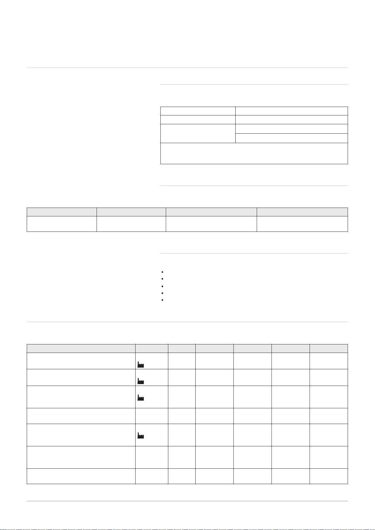
3.1.1 Certifications
Tab.1 Certifications
CE identification number PIN 0063CQ3781
Class NOx
(1)
Type of flue gas connection
6
(2)
B
23P
C13, C33, C53, C63, C
(1) EN 15502–1
(2) When installing a boiler with connection type B
is lowered to
IP20.
3.1.2 Unit categories
3 Technical specifications
93
, the IP rating of the boiler
23P
Tab.2 Unit categories
Country Category Gas type Connection pressure (mbar)
Great Britain II
2H3B/P
G20 (H gas)
G30/G31 (butane/propane)
3.1.3
Factory test
20
30-50
Before leaving the factory, each boiler is optimally set and tested for:
Electrical safety.
Adjustment of (O2/CO2).
Water tightness.
Gas tightness.
Parameter setting.
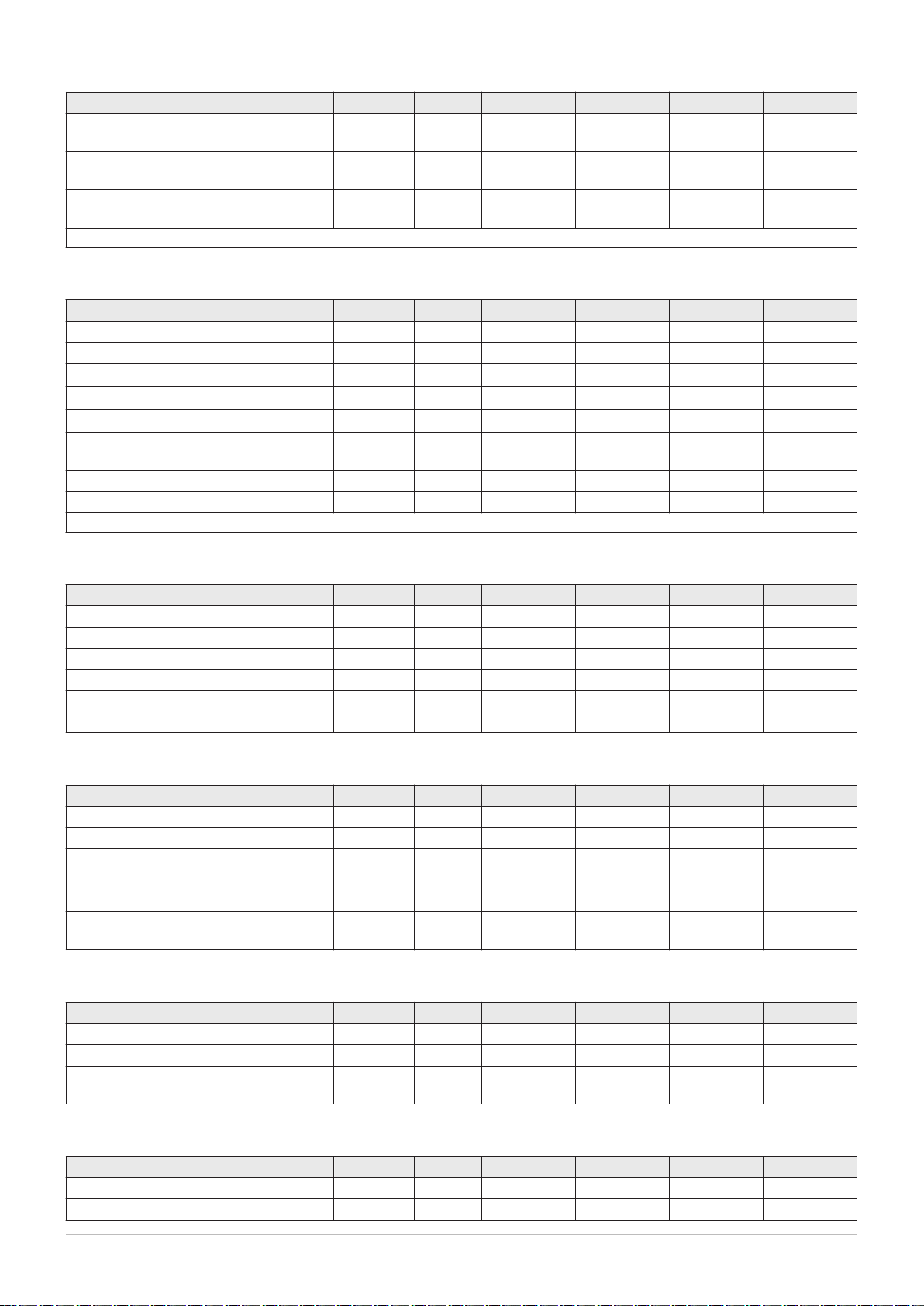
3.2
Technical data
Tab.3 General
Gas 220 Ace 160 200 250 300
Nominal output (Pn)
Central heating operation (80/60°C)
Nominal output (Pn)
Central heating operation (50/30°C)
Nominal load (Qnh)
Central heating operation (Hi) G20 (H-
min. - max.
(1)
min. - max.
(1)
min. - max.
(1)
kW 31.5 - 152.1
152.1
kW 34.7 - 161.1
161.1
kW 32.0 - 156.0
156.0
39.4 - 194.4
194.4
43.2 - 209.8
209.8
40.0 - 200.0
200.0
49.2 - 243.3
243.3
54.1 - 261.0
261.0
50.0 - 250.0
250.0
59.0 - 290.9
290.9
65.0 - 310.7
310.7
60.0 - 299.0
299.0
gas)
Nominal load (Qnh)
min. - max. kW 40.0 - 156.0 40.0 - 200.0 50.0 - 250.0 70.0 - 299.0
CH operation (Hi) G31 (propane)
Nominal load (Qnh)
Central heating operation (Hs) G20 (H-
min. - max.
(1)
kW 35.6 - 173.3
173.3
44.4 - 222.2
222.2
55.6 - 277.8
277.8
66.7 - 332.2
332.2
gas)
Nominal load (Qnh)
min. - max. kW 43.5 - 169.6 43.5 - 217.4 54.3 - 271.7 76.1 - 325.0
Central heating operation (Hs) G31 (pro
pane)
Full load central heating efficiency (Hi)
% 97.5 97.2 97.3 97.3
(80/60 °C) (92/42/EEC)
3 Technical specifications
14 7665063 - v.05 - 18102018
Gas 220 Ace 160 200 250 300
Full load central heating efficiency (Hi)
% 103.6 104.9 104.4 103.9
(50°C/30°C) (EN15502)
Part load central heating efficiency (Hi)
% 98.4 98.4 98.4 98.4
(return temperature 60°C)
Part load central heating efficiency
% 108.5 108.0 108.2 108.4
(92/42/EEC) (return temperature 30°C)
(1) Factory setting.
Tab.4 Gas and flue gas data
Gas 220 Ace 160 200 250 300
Gas inlet pressure G20 (H gas) min. - max. mbar 17 - 25 17 - 25 17 - 25 17 - 25
Gas inlet pressure G31 (propane) min. - max. mbar 37 - 50 37 - 50 37 - 50 37 - 50
Gas consumption G20 (H gas) min. - max.
Gas consumption G31 (propane) min. - max.
BREEAM NO
X
Flue gas quantity
(1)
mg/kWh 36 40 38 35
min. - max. kg/h
m3/h
m3/h
g/s
3.4 - 16.5 4.2 - 21.2 5.3 - 26.5 6.3 - 31.6
1.4 - 6.3 1.6 - 8.2 2.1 - 10.2 2.8 - 12.2
57 - 277
16 - 77
71 - 355
20 - 99
89 - 444
25 - 123
107 - 531
30 - 148
Flue gas temperature min. - max. °C 32 - 66 29 - 63 30 - 63 31 - 64
Maximum counter pressure Pa 200 150 150 150
(1) min = part load with Tr = 30 °C / max = full load with Tr = 60 °C
Tab.5 Central heating circuit data
Gas 220 Ace 160 200 250 300
Water content l 17.0 33.0 33.0 33.0
Water operating pressure min bar 0.8 0.8 0.8 0.8
Water operating pressure (PMS) max bar 5.0 6.0 6.0 6.0
Water temperature max °C 110.0 110.0 110.0 110.0
Operating temperature max °C 90.0 90.0 90.0 90.0
Hydraulic resistance (ΔT=20K) mbar 190 100 150 200
Tab.6 Electrical data
Gas 220 Ace 160 200 250 300
Supply voltage V~/Hz 230/50 230/50 230/50 230/50
Power consumption max W 275.0 204.0 323.0 343.0
Power consumption – part load min W 47.0 57.0 57.0 48.0
Power consumption – standby min W 5.3 11.0 11.0 9.0
Electrical protection index IP IPX1B IPX1B IPX1B IPX1B
Fuses Main
PCU
A 6.3
1.6
6.3
1.6
6.3
1.6
6.3
1.6
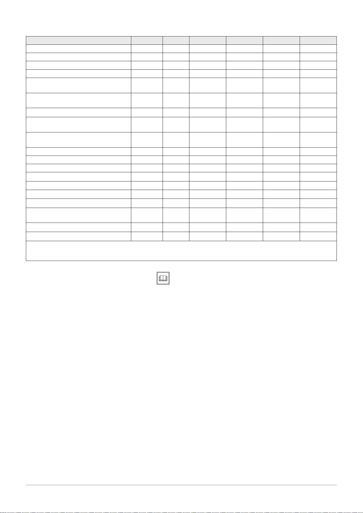
Tab.7 Other data
Gas 220 Ace 160 200 250 300
Total weight (including packaging) kg 235 275 275 275
Boiler weight kg 205 245 245 245
Average acoustic level at a distance of
dB(A) 58.7 59.7 63.8 63.8
one metre from the boiler
Tab.8 Technical parameters
Gas 220 Ace 160 200 250 300
Condensing boiler Yes Yes Yes Yes
Low-temperature boiler
(1)
No No No No
3 Technical specifications
7665063 - v.05 - 18102018 15
Gas 220 Ace 160 200 250 300
B1 boiler No No No No
Cogeneration space heater No No No No
Combination heater No No No No
Rated heat output
Useful heat output at nominal heat out
put and high temperature operation
Useful heat output at 30% of rated heat
output and low temperature regime
Seasonal space heating energy efficiency
Useful efficiency at rated heat output
and high temperature regime
(2)
Useful heat output at 30% of rated heat
output and low temperature regime
Prated
P
4
(2)
P
(2)
(2)
1
ƞ
s
ƞ
4
ƞ
1
kW 152 194 243 291
kW 152.1 194.4 243.3 290.9
kW 50.8 64.8 81.2 97.2
% - - - -
% 87.8 87.6 87.7 87.7
% 97.8 97.3 97.5 97.7
Auxiliary electricity consumption
Full load
Part load
Standby mode
elmax
elmin
P
SB
kW 0.275 0.204 0.323 0.343
kW 0.047 0.057 0.057 0.048
kW 0.005 0.011 0.011 0.009
Other items
Standby heat loss
Ignition burner power consumption
Annual energy consumption
P
stby
P
ign
Q
HE
kW 0.191 0.267 0.267 0.267
kW - - - -
kWh
- - - -
GJ
Sound power level, indoors
Emissions of nitrogen oxides NO
(1) Low temperature means 30 °C for condensing boilers, 37 °C for low temperature boilers and 50 °C (at heater inlet) for other heating
appliances.
(2) High temperature operation means 60 °C return temperature at heater inlet and 80 °C feed temperature at heater outlet.
L
WA
X
dB 67 68 72 72
mg/kWh 35 40 45 50
See
Refer to the back cover for contact details.
AD-3000809-01
528
62
272
738
657
800
458 171
1329
1662
332
56
383
231
84
3 Technical specifications
16 7665063 - v.05 - 18102018
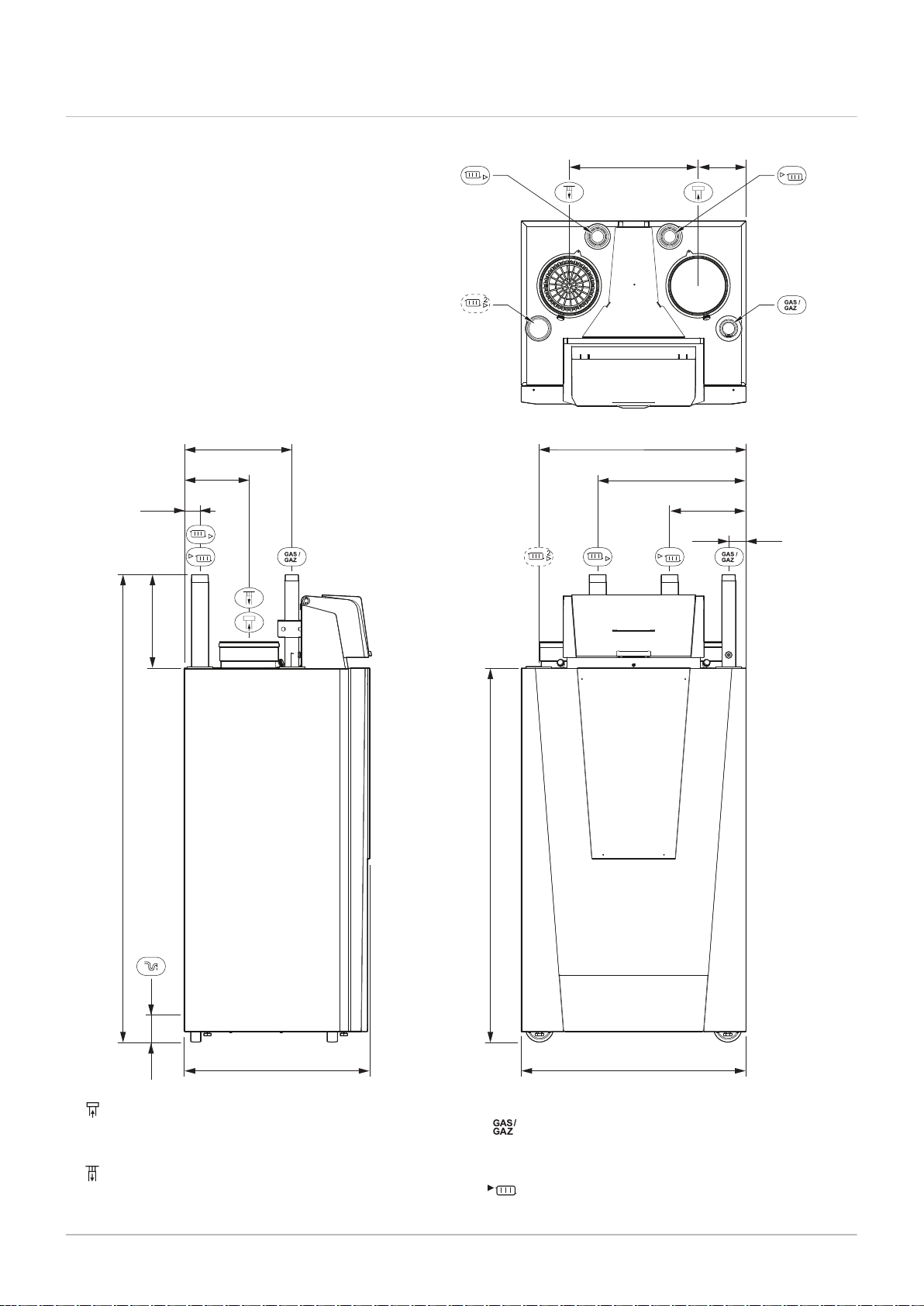
3.3 Dimensions and connections
Fig.1 Dimensions
Connecting the flue gas outlet;
Gas 220 Ace 160; Ø 150 mm
Gas 220 Ace 200 - 250 - 300; Ø 200 mm
Connecting the air supply;
Gas 220 Ace ; Ø 150 mm
Gas 220 Ace 200 - 250 - 300; Ø 200 mm
Gas connection;
Gas 220 Ace ; R 1 inch male thread
Gas 220 Ace 200 - 250 - 300; R 1½ inch male thread
Flow connection;
Gas 220 Ace ; R 1¼ inch male thread
AD-0001189-01
X01
X02
X03
X04 / X05
X06
X07
X12
X11
X10
X09
X08
Pump
N
L
OT
On/off
0
+
0 - 10
0
+
PWM
BL
RL
Tout
X1
X8
X10
X4X9
X5
X6
X2
X3
X1
1 32
X2
1 32
Pump
N
L
X3
1 32 4 5 6 7 8 9 10 11 12
On/off
OT
PWM
0 +
0 - 10
0 +
Tout
BL RL
X4
1 7-
6.3 AT
F1
X019 X039 X036
X5
1 7-
X6
1 15-
CB-01
X018 X035
X020
230VAC
X038
Bus
CU-GH & HMI
X12
1 5-
X122X121
X11
1 - 4
X111
X10
1 - 4
X101
X09
1 - 4
X08
1 13-
X083
X07
1 4-
X071
X06
1 4-
X04 / X05
1 15-
X041 X051 X053 X054 X055 X081
X02
1 9-
X03
1 15-
X021X022
X031
X015
X01
1 7-
X0141
X014
230V, 50Hz
X011
X013X012
X20 X202
X201
EMC
X037
Bus
2323
22
21
20
18 19
17
16
151413121110
9
87
6
5
3 4
2
1
3 Technical specifications
7665063 - v.05 - 18102018 17
Gas 220 Ace 200 - 250 - 300;R 2 inch male thread
Central heating return connection;
Gas 220 Ace ; R 1¼ inch male thread
Gas 220 Ace 200 - 250 - 300; R 2 inch male thread
Second central heating return connection (option);
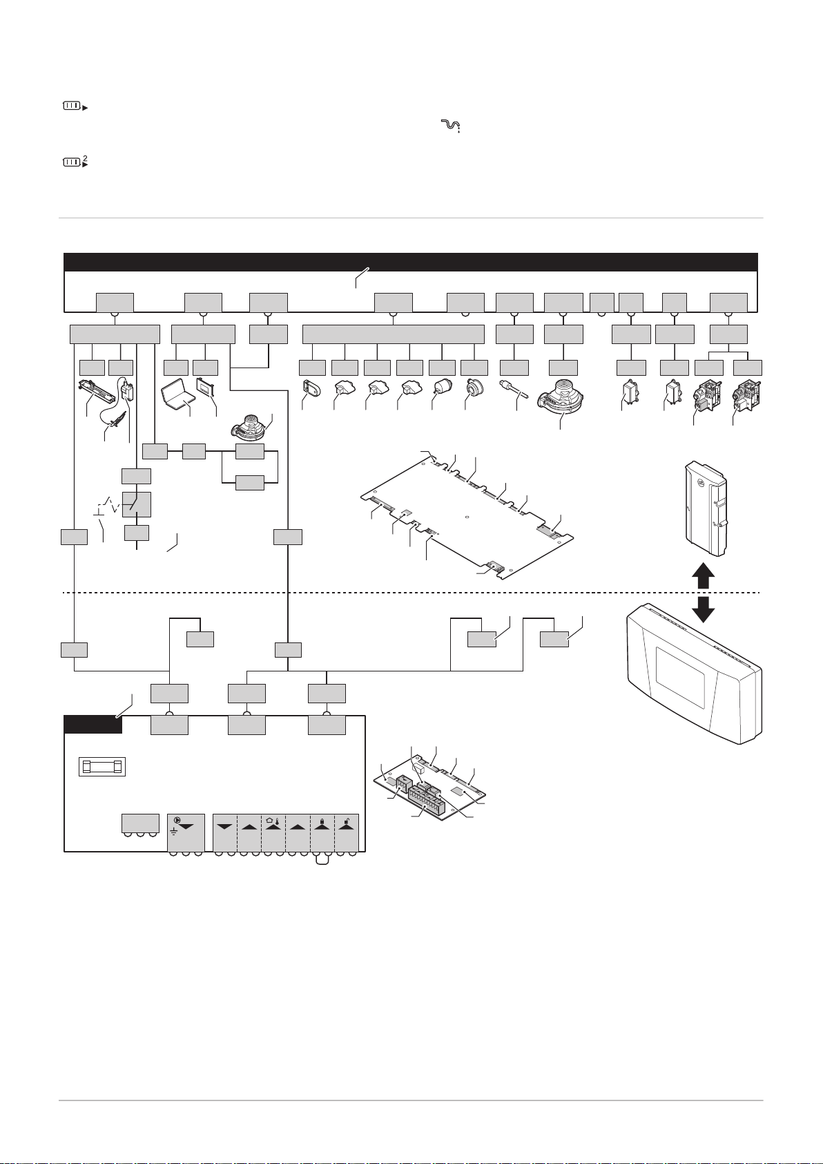
3.4 Electrical diagram
Fig.2 Electrical diagram
Gas 220 Ace ; R 1¼ inch male thread
Gas 220 Ace 200 - 250 - 300; R 2 inch male thread
Siphon connection
1
2
3
4
5
6
7
8
9
10
11
12
Boiler control unit
Lighting
Ionisation/ignition electrode (E)
Ignition transformer (IT)
On/Off switch (AU)
Power supply (P)
Service connector/computer connection (PC)
Control panel (HMI)
Fan supply (P)
Storage parameter (PSU)
Flow sensor (FTs)
Heat exchanger temperature sensor (HEs)
13
Return temperature sensor (RTs)
14
Hydraulic pressure sensor (WPs)
15
Air pressure differential switch (PS)
16
Flue gas sensor (FGs)
17
Fan control (PWM)
18
Gas leakage control VPS
19
Gas pressure switch GPS
20
Gas valve 1
21
Gas valve 2
22
Standard PCB
23
L-Bus connections for additional control PCBs
(depending on boiler model)

4 Description of the product
18 7665063 - v.05 - 18102018
4 Description of the product
The Gas 220 Ace boiler is delivered with a combination of the control
panel, control unit and extension PCB. The contents of this manual are
based on the following software and navigation information:
Tab.9 Software and navigation information
Name visible in display Software version
Boiler Gas 220 Ace FSB-WHB-HE-150-300 01.07
Control panel HMI S-control HMI 02.01
PCB SCB-01 SCB-01 00.02
4.1
Operating principle
4.1.1 Gas/air regulation
The boiler is equipped with a casing that also serves as an air box. The
fan draws in the combustion air. The gas is injected into the venturi and
mixed with the combustion air. The fan speed is controlled on the basis of
the settings, the heat demand and the prevailing temperatures measured
by the temperature sensors. The gas/air ratio control ensures an accurate
mixture of the required amounts of gas and air. This provides optimum
combustion over the entire heat input range. The gas/air mixture goes to
the burner, where it is ignited by the ignition electrode.
Important
The combustion air supply is checked before each burner start,
and at least once every 24 hours. During continuous operation
(e.g. supplying process water), please note that the boiler control
will reset every 24 hours.
4.1.2 Combustion
The burner heats the central heating water flowing through the heat
exchanger. If the temperature of the flue gases is lower than the dew point
(approx. 55°C), the water vapour condenses in the heat exchanger. The
heat released during this condensation process (referred to as the latent
or condensation heat) is also transferred to the central heating water. The
cooled flue gases are discharged through the flue gas discharge pipe. The
condensed water is discharged through a siphon.
4.1.3 Control system
The e-Smart electronic control system ensures that your heating system is
smart and reliable. This means that the boiler responds practically to
negative environmental influences (such as limited water flow and air flow
problems). In the event of such influences, the boiler will not go into
lockout mode, but in the first instance will modulate back. Depending on
the nature of the circumstances, a warning, blocking or lock-out may
occur. The boiler continues to supply heat provided the situation is not
dangerous. With this control system, your boiler is also equipped for
remote control and monitoring.
4.1.4 Control
On/off control
The heat input varies between the minimum and the maximum values
on the basis of the flow temperature set on the boiler. It is possible to
connect a 2-wire on/off thermostat or a power stealing thermostat to the
boiler.
Modulating control
The heat input varies between the minimum and the maximum values
on the basis of the flow temperature determined by the modulating

AD-0001329-02
100
150
300
0
0 2 41 3 5 8 9 10 11 12 13 14
6,7
15
250
50
190
4 Description of the product
7665063 - v.05 - 18102018 19
controller. The boiler output can be modulated with an appropriate
modulating controller.
Analogue control (0 - 10 V)
The heat input varies between the minimum and the maximum values
on the basis of the voltage present at the analogue input.
4.1.5 Regulating the water temperature
The boiler is fitted with an electronic temperature control with a flow and
return temperature sensor. The flow temperature can be adjusted between
20°C and 90°C. The boiler modulates back when the set flow temperature
is reached. The switch-off temperature is the set flow temperature + 5°C.
4.1.6 Protection against shortage of water
The boiler is fitted with low water level protection based on temperature
measurements. By modulating back when the water flow threatens to
become insufficient, the boiler remains operational as long as possible.
The boiler issues a warning in the event of no or too little water. With an
insufficient flow ΔT ≥ 25 K or too great an increase in the heat exchanger
temperature sensor, the boiler goes into blocking mode.
4.1.7 Water flow
The modulating control of the boiler limits the maximum difference
between the flow temperature and return temperature. In addition, a heat
exchanger temperature sensor is mounted to monitor the minimum water
flow. This limits the maximum increase in the heat exchanger temperature
and monitors the maximum temperature difference between the flow,
return and heat exchanger temperatures. As a result, the boiler is not
affected by low water flow.
4.1.8 Hydraulic pressure sensor
The hydraulic pressure sensor records the water pressure in the boiler.
Change the threshold value for the hydraulic pressure sensor using
parameter AP006.
4.1.9 Air pressure differential switch
The air pressure differential switch is a protection against a blocked trap or
blocked air supply/flue gas outlet.
Before start-up and when the boiler is in operation, the air pressure
differential switch APS measures the difference in pressure between the
measuring points on the condensate collector
p+ and the air box p-. If the
pressure difference is greater than 6 mbar, then the boiler will lock out.
After eliminating the cause of the breakdown, the boiler can be unlocked.
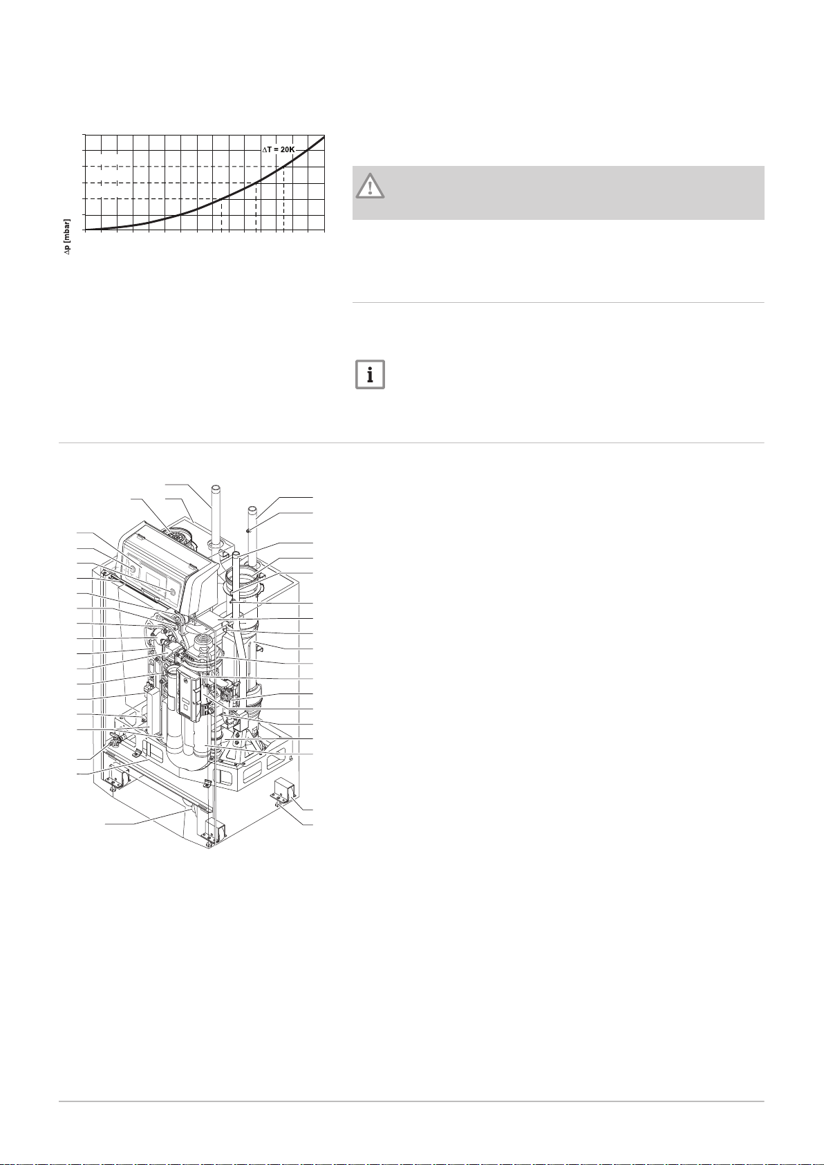
4.1.10 Circulating pump
Fig.3 Hydraulic resistance Gas 220 Ace
160
ΔP
Boiler resistance (mbar)
Q
Flow rate (m3/h)
AD-0001328-01
100
200
150
300
0
0
[m3/h]
Q
2 4 6 141 3 5 7
8,6 10,8 12,5
15
250
50
300 kW
250 kW
200 kW
AD-0001160-01
1
38
37
35
36
24
27
28
26
25
31
30
29
32
34
23
33
22
21
3
8
9
2
7
6
4
5
13
10
19
14
15
16
18
17
12
11
20
4 Description of the product
20 7665063 - v.05 - 18102018
Fig.4 Hydraulic resistance Gas 220 Ace
200 - 250 - 300
ΔP
Boiler resistance (mbar)
Q
Flow rate (m3/h)
The boiler is supplied without a pump. Take the boiler resistance and
system resistance into account when selecting a pump.
Caution
Maximum power consumption may be 300 VA. Use an auxiliary
relay for a pump with greater power.
4.1.11
Calorifier connection
A calorifier can be connected to the boiler. Our range includes various
calorifiers.
Important
Contact us for more information.
4.2
Fig.5 Main components
Main components
1
2
3
4
5
6
7
8
9
10
11
12
13
14
15
16
17
18
19
20
21
22
23
24
25
26
27
28
29
30
31
32
33
34
35
36
37
38
Central heating return pipe
Casing/air box
Air supply
Control panel
On/off switch
Service connector (PC connection)
LED interior light
Air pressure differential switch
Flow sensor
Burner
Adapter
Heat exchanger
Non-return valve
Temperature sensor for heat exchanger
Ignition transformer
Hydraulic pressure sensor
Heat exchanger inspection hatch
Filling/drain valve
Frame
Siphon
Adjustment bolt
Transport wheel
Air intake silencer
Condensate collector
Gas pressure measuring point
Venturi
Gas valve unit
Control unit (CU-GH)
Fan
Flue gas connection pipe
Flue gas sensor
Support
Gas pressure measuring point
Flue gas measuring point
Flue gas outlet
Gas connection
Manual air vent
Central heating supply pipe
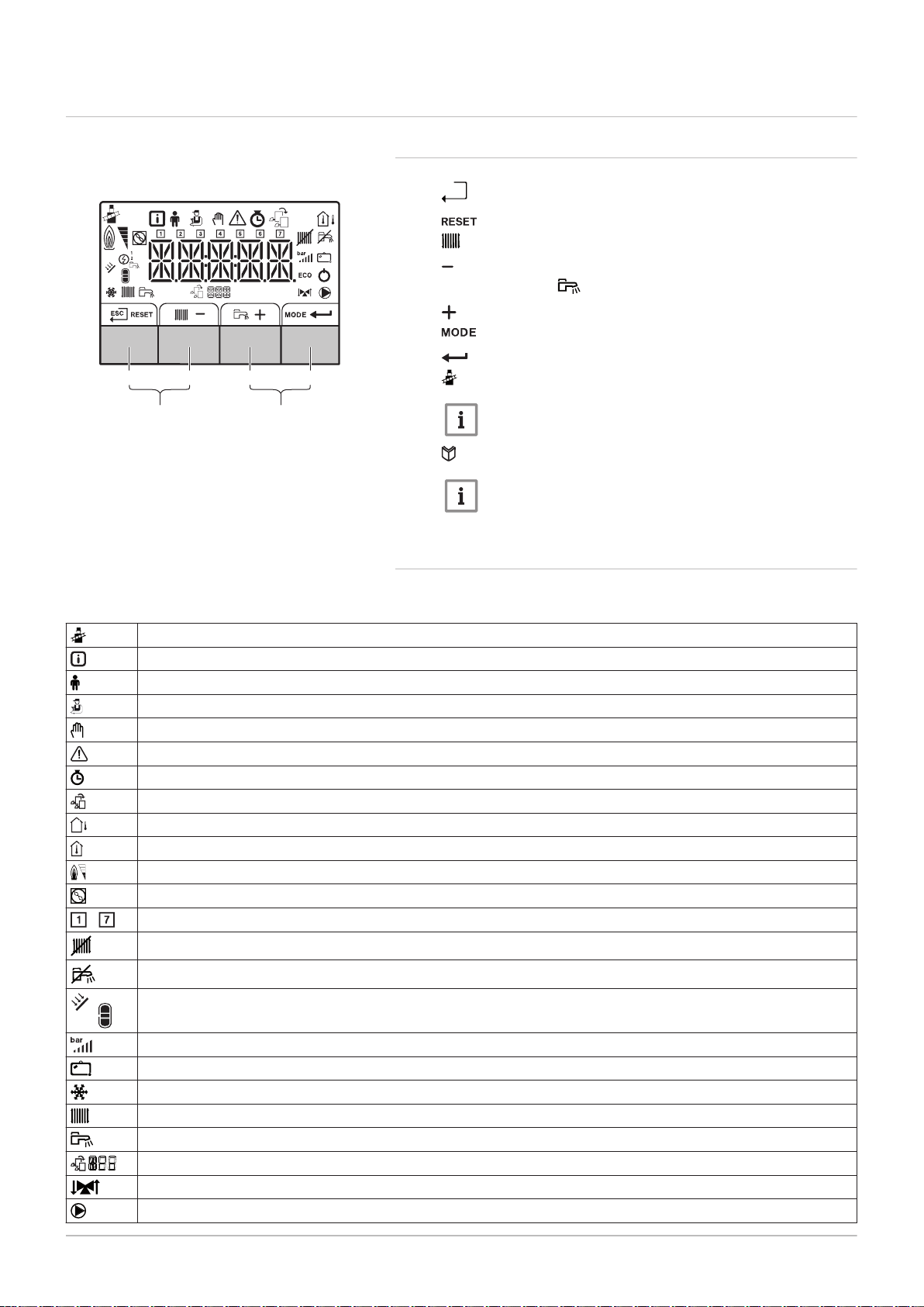
4.3 Control panel description
h
AD-3000833-01
1 2 3 4
5 6
7665063 - v.05 - 18102018 21
4 Description of the product
4.3.1 What each key means
Fig.6 Control panel
1
Escape: Back to the previous level.
Reset: Manual reset.
2
CH flow temperature Access to set temperature.
Min. key: Lowering the value.
3
DHW temperature: Access to set temperature.
Plus key: Raising the value.
4
5
6
CH/DHW function: Toggles function ON/OFF
Enter key: Confirms selection or value.
Chimney-sweeping keys
Important
Press the 1 and 2 keys simultaneously.
Menu keys
Important
Press the 3 and 4 keys simultaneously.
4.3.2 Meaning of the symbols on the display
Tab.10 Possible symbols in the display (depending on available devices or functions)
-
Chimney sweep mode is enabled (forced full load or part load for
Information menu: read out various current values.
User menu: user-level parameters can be configured.
Installer menu: installer level parameter can be configured.
Manual mode menu: manual mode can be configured.
Error menu: errors can be read out.
Hour counter/timer program/time display menu.
Control PCB menu: (optional) control PCBs can be read out.
The outside temperature sensor is connected.
The room temperature sensor is connected.
The burner output level (1 to 5 bars, with each bar representing 20% output)
The heat pump is switched on.
Day display
Central heating operation is switched off.
O2/CO2 measurement).
DHW operation is switched off.
The solar boiler is on and its heat level is displayed.
System water pressure display.
The holiday program is enabled.
Frost protection operation is enabled.
CH operation is enabled.
DHW operation is enabled.
Displaying the selected PCB.
The three-way valve is switched on.
The circulation pump is turning.
MW-3000377-02
MW-3000299-01
MW-3000300-02
MW-3000301-02
MW-3000302-01
MW-3000303-01
MW-3000304-01
4 Description of the product
22 7665063 - v.05 - 18102018
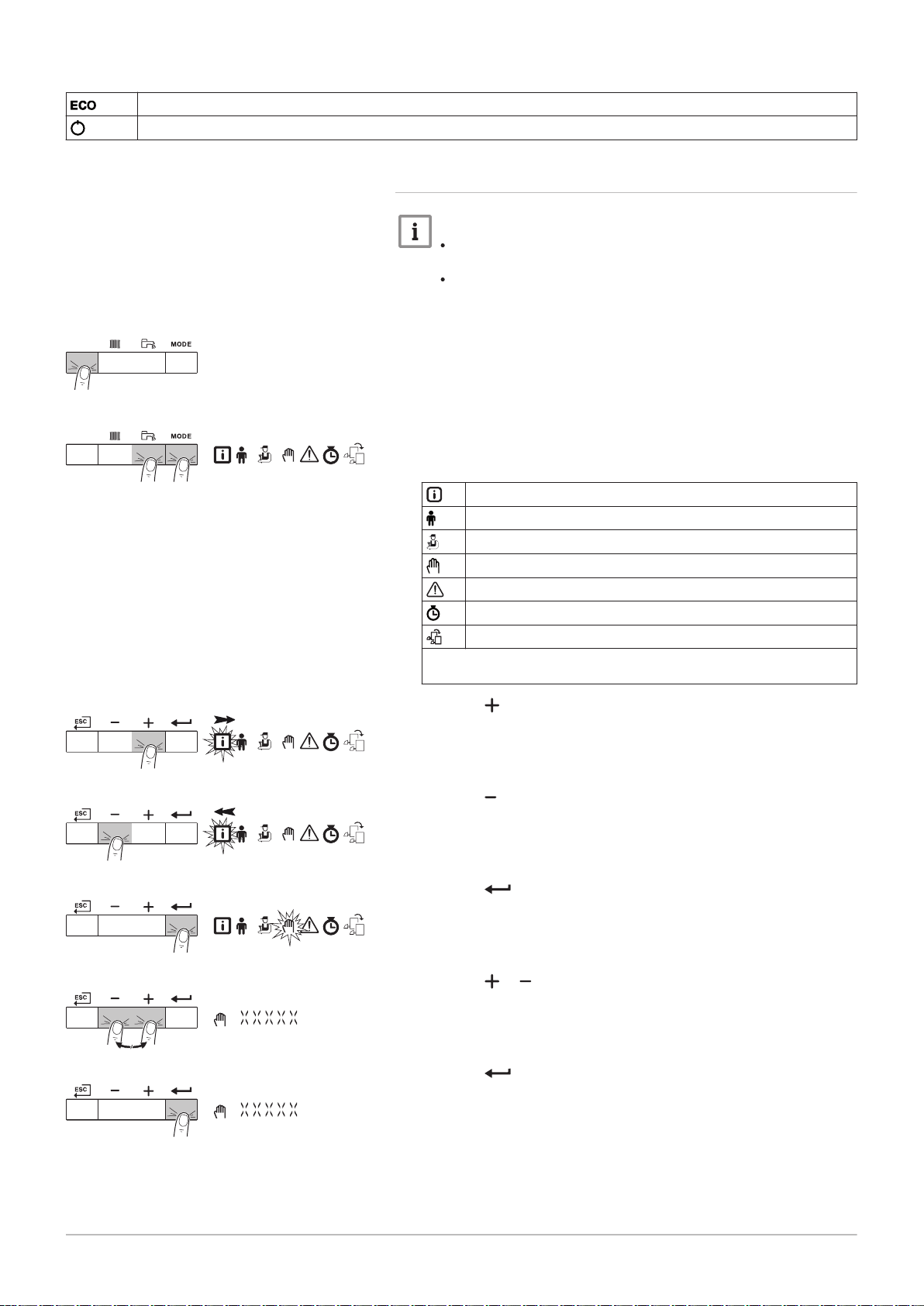
ECO mode operation is enabled.
Switch the appliance off then on again.
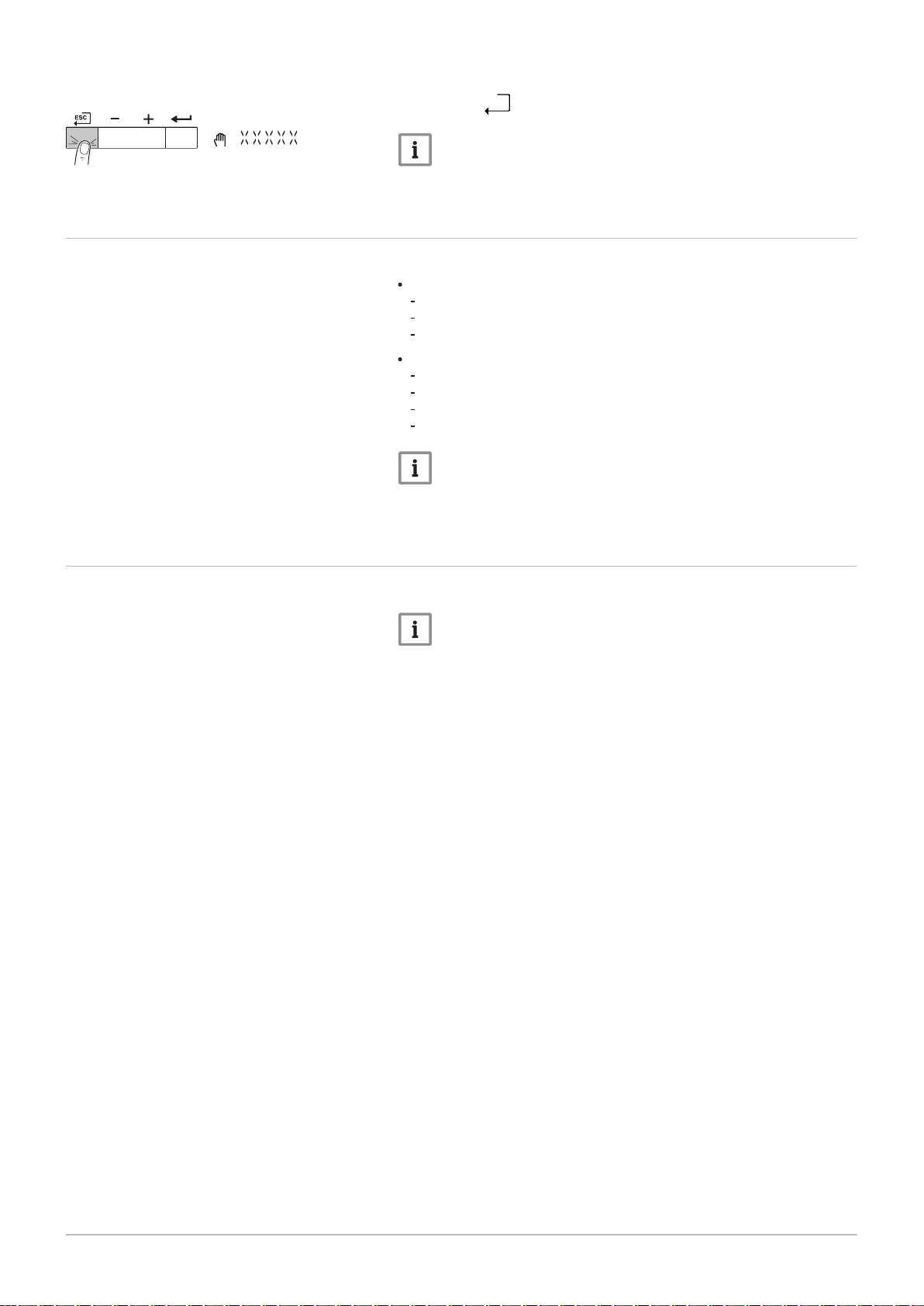
4.3.3 Browsing in the menus
Important
Depending on the devices or control PCBs connected, the
control panel shows selection options in some menus.
First, select a device, control PCB or zone to view or amend a
setting.
Fig.7
Step 1
Fig.8 Step 2
Fig.9 Step 3
1. Press any key to activate the controller from the stand-by screen.
2. Access the available menu options by pressing the two keys on the
right simultaneously.
Tab.11 Possible menu choices
Information Menu
User menu
Installer Menu
Manual mode menu
Failure Menu
Hour Run Meters / Timer Program / Clock menu
PCB menu
(1) The icon is displayed only if an optional control PCB has been instal
led.
(1)
3. Press the key to move the cursor to the right.
Fig.10 Step 4
Fig.11 Step 5
Fig.12 Step 6
Fig.13 Step 7
4. Press the key to move the cursor to the left.
5. Press the key to confirm selection of the required menu or
parameter.
6. Press the or key to modify the value.
7. Press the key to confirm the value.
MW-3000305-01
4 Description of the product
7665063 - v.05 - 18102018 23
Fig.14 Step 8
4.4 Standard delivery
8. Press the h key to go back to the main display.
Important
The screen will return to stand-by if no key is pressed for three
minutes.
The delivery includes 2 packages:
One package with:
The boiler, supplied with earthed mains plug
Documentation
Water quality instructions
One package with:
Siphon with condensate drain hose
Sticker: This central heating unit is set for...
The connection box
The control panel with a corresponding manual
Important
This manual only deals with the standard scope of supply. For the
installation or mounting of any accessories delivered with the
boiler, refer to the corresponding mounting instructions.
4.5 Accessories and options
Various accessories can be obtained for the boiler.
Important
Contact us for more information.
AD-0001162-01
AD-0001163-01
800 100100
657 50
1100
1662 A
5 Before installation
24 7665063 - v.05 - 18102018
5 Before installation
5.1 Installation regulations
Warning
The installer must be registered with Gas Safe and have the
correct ACS qualifications.
Important
Practical guidelines - see the latest version.
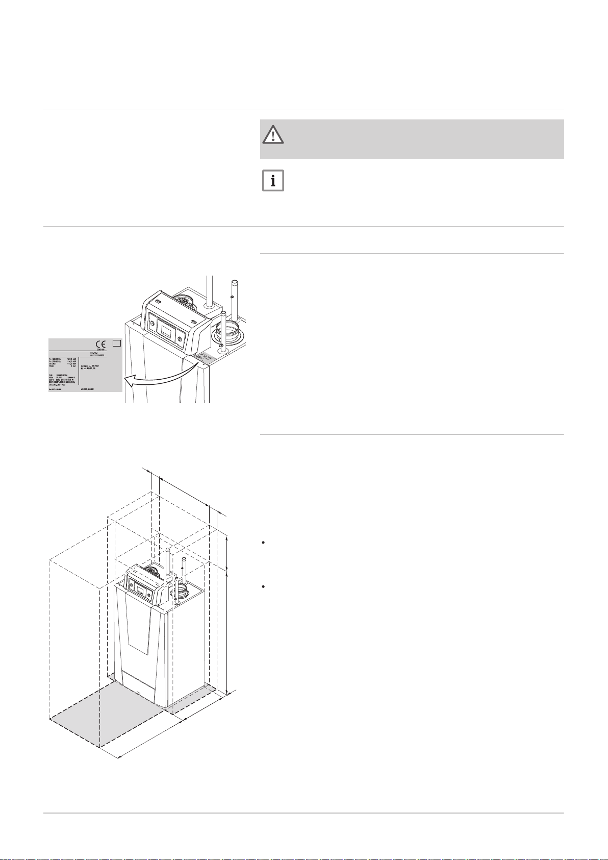
5.2
Fig.15
Fig.16 Clearance required
Choice of the location
Position of data plate
5.2.1 Data plate
The data plate on the boiler features the boiler serial number and
important boiler specifications, for example the model and unit category.
The factory setting codes CN 1 and CN 2 are also stated on the data
plate.
5.2.2 Location of the boiler
A
500 mm (if the air supply filter is used, there must be a clearance
of at least 650 mm)
The standard inspection and maintenance operations to the boiler are
carried out from the front. This is also where the inspection ports of the
heat exchanger are located. The hydraulic connections and the flue gas
outlet are located at the front of the boiler. The control panel housing is
also on the front of the boiler.
Use the guidelines and the required installation space as a basis for
determining the correct place to install the boiler.
When determining the correct installation space, take account of the
permitted position of the flue gas discharge and/or air supply outlet.
Ensure that there is sufficient space around the boiler for good access
and ease of maintenance.
AD-0001164-01
1200
1835
800
5 Before installation
7665063 - v.05 - 18102018 25
Danger
It is forbidden to store, even temporarily, combustible products
and substances in or near the boiler.
Caution
The boiler must be installed in a frost-free area.
The boiler must have an earthed electrical connection.
A connection to the drain must be present for the condensate
drain close to the boiler.
A technical clearance of at least 1100 mm is required at the
front (service side) of the boiler. We recommend a clearance of
at least 500 mm above the boiler.
Caution
If the power supply cable is permanently connected, you must
always install a main bipolar switch with an opening gap of at least
3 mm (BS EN 60335-1).
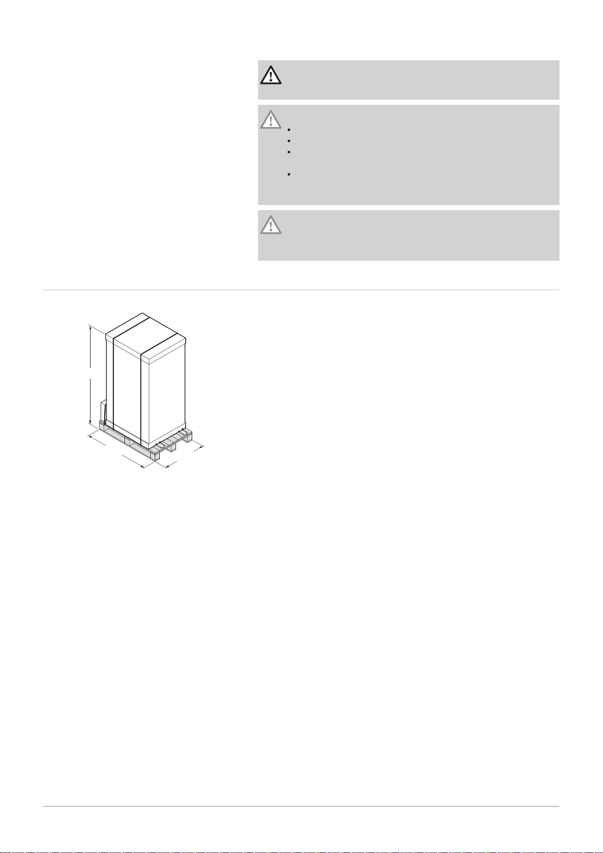
5.3
Fig.17
Transport
Boiler package
The boiler is supplied fully assembled and packaged on a pallet. Without
the packaging, the boiler will fit through all standard doorways.
The boiler is equipped with integrated transport wheels, meaning it can
easily be moved.
AD-0001165-01
8
7
6
5
5
3
4x
4
4x
1
2
5 Before installation
26 7665063 - v.05 - 18102018
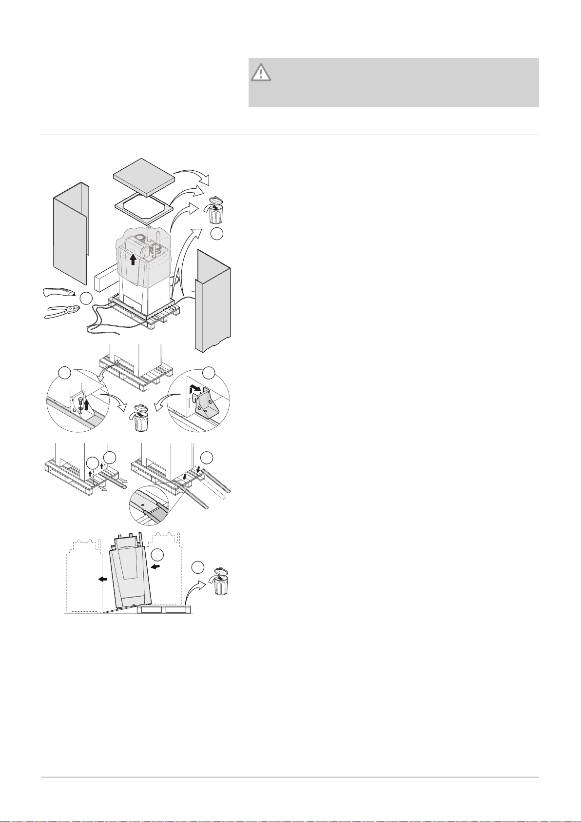
5.4 Unpacking & initial preparation
Caution
The transport wheels under the boiler are designed for transport
purposes only and not for use when the boiler is in its final
position.
Fig.18 Unpacking the boiler
1. Cut the packaging straps and remove.
2. Remove the packaging.
3. Unscrew the boiler anchorage on the pallet.
4. Remove the boiler anchorage.
5. Unscrew the loading ramps on the pallet.
6. Fit the loading ramps in front of the pallet.
7. Move the boiler off the pallet.
8. Remove the pallet and the rest of the packaging.
The boiler can now be moved using the transport wheels.
6 Installation
AD-0001166-02
4x
4x
63 63
80
80
485
55
55
674
7665063 - v.05 - 18102018 27
6.1 General
6 Installation
Warning
The boiler must be installed by a qualified installer in accordance
with local and national regulations.
6.2
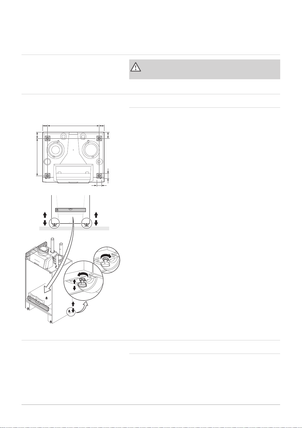
Fig.19 Position of the adjustment bolts
Preparation
6.2.1 Positioning the boiler
1. Place the boiler in the right position using the transport wheels.
2. Loosen the adjustment bolts and ensure that the boiler is completely
level.
The figure also shows the support surface of the boiler (this is the position
of the adjustment bolts).
6.3
Hydraulic connections
6.3.1 Rinsing the system
The installation must be cleaned and flushed in accordance with BS 7593
(2006) and BSRIA BG 33/2014.
Before a new boiler can be connected to an existing or new system, the
entire system must be thoroughly cleaned and flushed. This step is
absolutely crucial. The flushing helps to remove residue from the
installation process (weld slag, fixing products etc.) and accumulations of
dirt (silt, mud etc.)
AD-0001167-01
6 Installation
28 7665063 - v.05 - 18102018
Important
Flush the system with a volume of water equivalent to at least
three times the volume of the system.
Flush the DHW pipes with at least 20 times the volume of the
pipes.
Important
Due to the presence of an aluminium heat exchanger, suitable
chemicals and the correct use of these chemicals should be
discussed with specialist water treatment companies.
6.3.2 Connecting the heating circuit
Fig.20 Supply and return connections
1. Remove the dust cap on the central heating flow connection .
2. Remove the dust cap on the central heating return connection .
3. Fit the outlet pipe for CH water to the CH flow .
4. Fit the inlet pipe for CH water to the CH return .
5. In the supply directly above the boiler, establish a connection for a
overpressure valve of sufficient capacity.
6. Connect the pump to the boiler's return connection.
Always connect the boiler in a way that will guarantee the water flow
through the unit during operation. When the boiler is used in a system with
two return pipes, the return pipe must be used as a cold return. The
second return pipe is then used as a hot return. Contact us for more
information.

Caution
AD-0001168-02
6
1
7
3
54
2
AD-0001174-01
7665063 - v.05 - 18102018 29
If using plastic pipes, follow the manufacturer's (connection)
instructions.
6.3.3 Connecting the condensate drain pipe
6 Installation
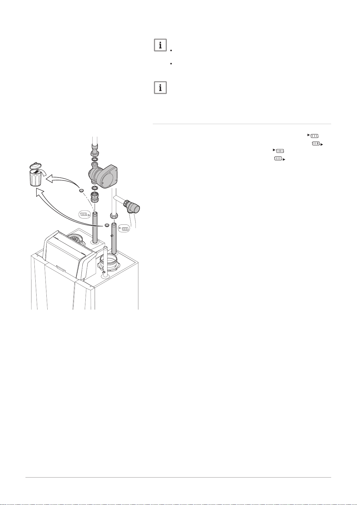
Fig.21 Connect the condensate drain pipe
The siphon is supplied separately with the boiler as standard (including a
flexible plastic siphon hose). .
1. Remove the dust cap from the siphon connection at the bottom of
the boiler
2. Pull the retainer clip of the siphon backwards.
3. Push the siphon firmly in the holder.
4. Push the retainer clip of the siphon forwards.
5. Check whether the siphon is firmly fitted in the boiler.
6. Attach the flexible siphon hose supplied to the output of the siphon
and insert the other end into the plastic drain pipe on the left
underneath the boiler.
7. Fit a plastic drain pipe of Ø 40 mm or larger to this, terminating in the
drain.
Important
The air opening on the siphon prevents siphoning when the drain
pipe is securely connected to the drain.
Danger
The siphon must always be filled with water. This prevents flue
gases from entering the room.
Caution
The drain pipe must slope down at least 30 mm per metre.
Condensed water must not be discharged into a gutter.
6.4 Gas connection
Fig.22 Gas connection
Warning
Before starting work on the gas pipes, turn off the main gas tap.
Before installing, check that the gas meter has sufficient
capacity. Take into account the consumption of all appliances.
Notify the local energy company if the gas meter has insufficient
capacity.
1. Remove the dust cap on the gas connection .
2. Fit the gas supply pipe.
Caution
Always perform welding work at a sufficient distance from the
boiler.
Remove dirt and dust from the gas pipe.
Important
We recommend installing a gas filter to prevent clogging of the
gas valve unit.
3. Also fit a gas isolation valve in this pipe, near the boiler.

AD-3001055-01
AD-3001056-01
AD-3001057-01
6 Installation
30 7665063 - v.05 - 18102018
6.5 Air supply/flue gas outlet connections
6.5.1 Classification
Important
The installer is responsible ensuring that the right type of flue
gas outlet system is used and that the diameter and length are
correct.
Always use connection materials, roof terminal and/or outside
wall terminal supplied by the same manufacturer. Consult the
manufacturer for compatibility details.
Tab.12 Type of flue gas connection: B
23P
Principle Description
Room-ventilated version
Without down-draught diverter.
Flue gas discharge via the roof.
Air from the installation area.
The IP rating of the boiler is lowered to IP20.
(1) The material must also satisfy the material property requirements from the relevant chapter.
Tab.13 Type of flue gas connection: C
13
Principle Description
Room-sealed version
Discharge in the outside wall.
Air supply opening is in the same pressure zone as the dis
charge (e.g. a combined outside wall terminal).
Parallel not permitted.
Permitted manufacturers
(1)
Connection material and roof
terminal:
Muelink & Grol
Permitted manufacturers
(1)
Outside wall terminal and con
nection material:
Remeha, combined with con
nection material from Muelink
& Grol
Muelink & Grol
(1) The material must also satisfy the material property requirements from the relevant chapter.
Tab.14 Type of flue gas connection: C
33
Principle Description
Room-sealed version
Flue gas discharge via the roof.
Air supply opening is in the same pressure zone as the dis
charge (e.g. a concentric roof terminal).
(1) The material must also satisfy the material property requirements from the relevant chapter.
Permitted manufacturers
(1)
Roof terminal and connection
material
Remeha, combined with con
nection material from Muelink
& Grol
Muelink & Grol

AD-3001058-02
AD-3001059-01
6 Installation
7665063 - v.05 - 18102018 31
Tab.15 Type of flue gas connection: C
53
Principle Description
Connection in different pressure zones
Closed unit.
Separate air supply duct.
Separate flue gas discharge duct.
Discharging into various pressure areas.
The air supply and the flue gas outlet must not be placed on
opposite walls.
(1) The material must also satisfy the material property requirements from the relevant chapter.
Tab.16 Type of flue gas connection: C
63
Principle Description
This type of unit is supplied by the manufacturer without an air
supply system and flue gas system.
(1) The material must also satisfy the material property requirements from the relevant chapter.
Permitted manufacturers
(1)
Connection material and roof
terminal:
Muelink & Grol
Permitted manufacturers
(1)
When selecting the material,
please note the following:
Condensed water must flow
back to the boiler.
The material must be resist
ant to the flue gas tempera
ture of this boiler.
Maximum permissible recir
culation of 10%.
The air supply and the flue
gas outlet must not be placed
on opposite walls.
Minimum permitted pressure
difference between the air
supply and the flue gas outlet
is -200 Pa (including -100 Pa
wind pressure).
Tab.17 Type of flue gas connection: C
Principle
(1)
Description
Room-sealed version
Air supply and flue gas discharge duct in shaft or ducted:
93
Concentric.
Permitted manufacturers
Connection material and roof
terminal:
Muelink & Grol
Air supply from existing duct.
Flue gas discharge via the roof.
Inlet opening for the air supply is in the same pressure zone
as the discharge.
(1) See table for shaft or duct requirements.
(2) The material must also satisfy the material property requirements from the relevant chapter.
Tab.18 Minimum dimensions of shaft or duct C
93
Version (D) Without air supply With air supply
Rigid 150 mm Ø 200 mm □ 200 x 200 mm Ø 220 mm □ 220 x 220 mm
Rigid 200 mm Ø 250 mm □ 250 x 250 mm Ø 280 mm □ 280 x 280 mm
Concentric 150/200 mm Ø 270 mm □ 270 x 270 mm - -
(2)

AD-3000330-03
□
D
Ø
D
AD-3001120-01
EN 14471 - T120 P1 W 1 O50 LI E U0
EN 1856-1 - T120 P1 W VxL40045 G(xx)
1
3
2
4
5
6 Installation
32 7665063 - v.05 - 18102018
Fig.23 Minimum dimensions of shaft or
duct C
93
Fig.24 Sample string
Important
The shaft must comply with the air density requirements of the
local regulations.
Important
Always clean shafts thoroughly when using lining pipes and/or
an air supply connection.
It must be possible to inspect the lining duct.
6.5.2 Material
Use the string on the flue gas outlet material to check whether it is suitable
for use on this appliance.
1
EN 14471 of EN 1856–1: The material is CE approved according to
this standard. For plastic this is EN 14471, For aluminium and
stainless steel this is EN 1856-1.
2
T120: The material has temperature class T120. A higher number
is also allowed, but not lower.
3
P1: The material falls into pressure class P1. H1 is also allowed.
4
W: The material is suitable for draining condensation water
(W=’wet’). D is not allowed (D=’dry’).
5
E: The material falls into fire resistance class E. Class A to D are
also allowed, F is not allowed. Only applicable to plastic.
Warning
The coupling and connection methods may vary depending on
the manufacturer. It is not permitted to combine pipes, coupling
and connection methods from different manufacturers. This also
applies to roof feed-throughs and common channels.
The materials used must comply with the prevailing regulations
and standards.
Please contact us to discuss using flexible flue gas outlet
material.
Tab.19 Overview of material properties
Version Flue gas outlet Air supply
Material Material properties Material Material properties
Single-wall, rigid
(1)
Plastic
Stainless steel
Thick-walled,
aluminium
(2)
With CE marking
(2)
Temperature class T120 or
higher
Condensate class W (wet)
Plastic
Stainless steel
Aluminium
Pressure class P1 or H1
Fire resistance class E or bet
(3)
ter
(1) according to EN 14471
(2) according to EN 1856
(3) according to EN 13501-1
With CE marking
Pressure class P1 or H1
Fire resistance class E or bet
(3)
ter

6.5.3 Dimensions of flue gas outlet pipe
AD-3001094-01
ød
1
AD-3000963-01
ød
1
øD
1
AD-0001169-01
L
=
7665063 - v.05 - 18102018 33
Warning
The pipes connected to the flue gas adapter must satisfy the
following dimension requirements.
6 Installation
Fig.25
Dimensions of open connection
Fig.26 Dimensions of parallel connection
d
External dimensions of flue gas outlet pipe
1
Tab.20 Dimensions of pipe
d1 (min-max)
150 mm 149 - 151 mm
200 mm 199 - 201 mm
d
External dimensions of flue gas outlet pipe
1
D
External dimensions of air supply pipe
1
Tab.21 Dimensions of pipe
d1 (min-max) D1 (min-max)
150/150 mm 149 - 151 mm 149 - 151 mm
6.5.4 Length of the air and flue gas pipes
Fig.27 Room-ventilated version
The maximum length of the flue gas outlet and air supply channel vary
depending on the appliance type; consult the relevant chapter for the
correct lengths.
Important
When using bends, the maximum chimney length (L) must be
shortened according to the reduction table.
For adaptation to another diameter use approved transitions
The boiler is also suitable for longer chimney lengths and
diameters other than those specified in the tables. Contact us
for more information.
Room-ventilated model (B
L
Length of the flue gas outlet channel to roof feed-through
23P
)
Flue gas outlet
Air supply
With a room-ventilated version, the air supply opening stays open; only the
flue gas outlet opening is connected. This will ensure that the boiler
obtains the necessary combustion air directly from the installation area.
Use adapters when using air supply and flue gas discharge pipes with
diameters other than the standard 150 or 200 mm.

AD-0001170-01
L =L
= +
6 Installation
34 7665063 - v.05 - 18102018
Caution
The air supply opening must stay open.
The installation area must be equipped with the necessary air
supply openings. These openings must not be obstructed or
shut off.
If the boiler, in room-ventilated operation, has been set up in a
(very) dusty room, use the air supply filter (accessory).
Use of the air inlet filter is compulsory when the boiler is
exposed to building dust.
Tab.22 Maximum chimney length (L)
Diameter 130 mm 150 mm 200 mm 250 mm
Gas 220 Ace 160 37 m
50 m
(1)
Gas 220 Ace 200 16 m 35 m
Gas 220 Ace 250 10 m 21 m
Gas 220 Ace 300 7 m 15 m
(1) With retention of the maximum flue length it is possible to apply an extra 5
times 90º or 10 times 45º elbows.
50 m
50 m
50 m
50 m
(1)
50 m
(1)
50 m
(1)
50 m
(1)
50 m
Room-sealed model (C13, C33, C63, C93)
(1)
(1)
(1)
(1)
Fig.28 Room-sealed version
L
Combined length of the flue gas outlet and air supply channel to
the roof feed-through
Flue gas outlet
Air supply
With a room-sealed version, both the flue gas outlet and the air supply
openings are connected (in parallel). Use adapters when using air supply
and flue gas discharge pipes with diameters other than the standard 150
or 200 mm.
Tab.23 Maximum chimney length (L)
Diameter 130 mm 150 mm 200 mm 250 mm
Gas 220 Ace 160 18 m 62 m
Gas 220 Ace 200 - 10 m
100 m
100 m
(1)
(1)
Gas 220 Ace 250 - - 74 m
Gas 220 Ace 300 - - 40 m
(1) With retention of the maximum flue length it is possible to apply an extra 5
times 90º or 10 times 45º elbows.
100 m
100 m
100 m
100 m
(1)
(1)
(1)
(1)

Connection in different pressure areas (C53)
AD-0001171-01
L
=
+
7665063 - v.05 - 18102018 35
6 Installation
Fig.29
Different pressure zones
L
Total length of the flue gas outlet and air supply duct
Connecting the flue gas outlet
Connecting the air supply
Combustion air supply and flue gas discharge are possible in different
pressure areas and semi-CLV systems, with the exception of the coastal
area. The maximum permitted height difference between the combustion
air supply and the flue gas outlet is 36 m.
Tab.24 Maximum chimney length (L)
Diameter 130 mm 150 mm 200 mm 250 mm
Gas 220 Ace 160 27 m 64 m
Gas 220 Ace 200 7 m 21 m
Gas 220 Ace 250 - 11 m 74 m
Gas 220 Ace 300 - 5 m 48 m
(1) With retention of the maximum flue length it is possible to apply an extra 5
times 90º or 10 times 45º elbows.
100 m
100 m
(1)
100 m
(1)
100 m
100 m
100 m
Reduction table
Tab.25 Pipe reduction for each element used (parallel)
Diameter 80 mm 90 mm 100 mm 110 mm 130 mm 150 mm 250 mm 300 mm
45° bend 1.2 m 1.3 m 1.4 m 1.5 m 1.0 m 1.2 m 2.0 2.4
90° bend 4.0 m 4.5 m 4.9 m 5.4 m 1.8 m 2.1 m 3.5 4.2
(1)
(1)
(1)
(1)
Tab.26 Pipe reduction for each element used (concentric)
Diameter 80/125 mm 100/150 mm 130/200 mm 150/220 mm
45° bend 1.0 m 1.0 m 1.5 m 1.5 m
90° bend 2.0 m 2.0 m 3.0 m 3.0 m
6.5.5 Additional guidelines
Installation
For installing the flue gas outlet and air supply materials, refer to the
instructions of the manufacturer of the relevant material. After
installation, check at least all flue gas outlet and air supply parts for
tightness.
Warning
If the flue gas outlet and air supply materials are not installed in
accordance with the instructions (e.g. not leak-proof, not correctly
bracketed), this can result in dangerous situations and/or physical
injury.
Make sure that the flue gas outlet pipe towards the boiler has a sufficient
gradient (at least 50 mm per metre) and that there is a sufficient
condensate collector and discharge (at least 1 m before the outlet of the
boiler). The bends used must be larger than 90° to guarantee the
gradient and a good seal on the lip rings.
Condensation
Direct connection of the flue gas outlet to structural ducts is not
permitted because of condensation.
If condensate from a plastic or stainless steel pipe section can flow back
to an aluminium part in the flue gas outlet, this condensate must be
discharged via a collector before it reaches the aluminium.

AD-0001172-01
S
Ø150 mm
AD-0001173-01
S
Ø150 mm
6 Installation
36 7665063 - v.05 - 18102018
Important
Contact us for more information.
Fig.30 Connecting the flue gas outlet
Fig.31 Connecting the air supply
6.5.6
Connecting the flue gas outlet
S Insertion depth 30 mm
1. Fit the flue gas outlet pipe to the boiler.
2. Fit the successive flue gas outlet pipes seamlessly together.
Caution
The pipes must be flue gas-tight and corrosion-resistant.
The flue gas outlet pipe must be smooth and deburred.
Connect the pipes so that they are stress-free.
The pipes must not rest on the boiler.
Fit the horizontal parts sloping down towards the boiler, with a
slope of 50 mm per metre.
6.5.7 Connecting the air supply
S Insertion depth 30 mm
1. Fit the air supply pipe to the boiler.
2. Fit the successive air supply pipes seamlessly together.
Caution
The pipes must be airtight and corrosion-resistant.
The air supply pipe must be smooth and deburred.
Connect the pipes so that they are stress-free.
The pipes must not rest on the boiler.
Fit the horizontal parts sloping down towards the air supply
outlet.

6.5.8 Specific air and flue gas applications
AD-0000915-01
X07
X08
X10
X09
X11
X12
X06
X05
X04
X03
X02
X01
7665063 - v.05 - 18102018 37
Important
If the boiler is used in a flue gas overpressure cascade, this must
be stated on the sticker supplied: This central heating unit is set
for... This sticker must be affixed next to the data plate of the
boiler.
Contact us for more information.
6 Installation
6.6
Fig.32
Electrical connections
Connectors from the control unit
CU-GH (front view)
6.6.1 Recommendations
Warning
Electrical connections must always be made with the power
supply disconnected and only by qualified installers.
The boiler is completely pre-wired. Never change the internal
connections of the control panel.
Always connect the boiler to a well-earthed installation.
Establish the electrical connections in accordance with:
The instructions of the current standards.
The instructions of the wiring diagrams supplied with the boiler.
The recommendations in this manual.
Separate the sensor cables from the 230 V cables
6.6.2 Control unit
The table gives important connection values for the control unit.
Tab.27 Connection values for control unit
Supply voltage 230 VAC/50 Hz
Main fuse value F1 (230 VAC) 6.3 AT
Fuse value F2 (230 VAC) 1.6 AT
Fan 230 VAC
Danger of electric shock
The following components of the boiler are connected to a 230 V
power supply:
Electrical connection to circulating pump.
Electrical connection to gas combination block.
Electrical connection to fan.
Control unit.
Ignition transformer.
Power supply cable connection.
Various connections in the connection box.
The mains lead of the boiler has an earthed plug (lead length 1.5 m) and is
suited for a 230 VAC/50 Hz with a phase/neutral/earth system.
The boiler is not phase sensitive. The boiler is completely pre-wired

AD-0001175-01
AD-0001300-01
B
X021
6 Installation
38 7665063 - v.05 - 18102018
Caution
Always order a replacement mains lead from Remeha. The
power supply cable should only be replaced by Remeha , or by
an installer certified by Remeha .
The plug of the boiler must always be accessible.
The control panel must still be fitted in the control panel housing. The
connection box with the terminals of the connector for external
connections is located behind the control panel. The optional PCBs are
also placed in the connection box. The wiring for the external connections
is fed through a cable duct to the back of the boiler.
6.6.3 Assembly of the control panel
Fig.33
Control panel housing
Fig.34 PCB
The Gas 220 Ace boiler is supplied with a separate control panel. The
control panel is fitted in the control panel housing. The cable behind the
control panel with connector X021 must be slid onto the connector pin (5
pins, 24V) of the PCB.
B
Battery
There is also a back-up battery on the PCB for the internal clock. Check
the battery voltage if the date and time are not displayed clearly.

6.6.4 Installation of the connection box
AD-0001176-01
8
90º
9
7.1
7.2
7.6
7.3
7.4
7.5
90º
1
2
6
6
5
4
3
5
X035
X018
7665063 - v.05 - 18102018 39
6 Installation
Fig.35 Installing and connecting the
connection box
The connection box contains the standard PCB CB-01 and the optional
PCB(s) for the external connections. The connection box is included with
the delivery of the boiler as standard. Use the connection cables supplied
to connect the connection box to the control unit. Proceed as follows:
1. Unscrew the retaining screw on the front of the housing.
2. Open the front flap of the housing.
3. Connect the connection cable X035 to the connector from the boiler.
4. Connect the connection cable X018 to the connector from the boiler.
5. Place the connection box for the mounting clips in the housing.
6. Carefully push the connection box downwards over the mounting clips
and tighten the two screws.
7. Now connect the desired external controllers to the other connectors.
Proceed as follows:
7.1. Unscrew the retaining screw on the cable duct cover.
7.2. Remove the cable duct cover.
7.3. Route the cable of the external controllers or the sensor
through the cable duct.
7.4. Lay the cable under the strain relief clip.
7.5. Turn the strain relief clip firmly into place.
7.6. Replace the cable duct cover and tighten the retaining screw.
8. Close the front flap of the housing.
9. Retighten the retaining screw on the front of the housing.

AD-3000672-02
Pump
N L
+0 +0
0-10PWM
Tout OT BL RL
On/off
AD-3001306-01
N L
AD-3001307-01
+
-
PWM
AD-3001308-01
OT
On/off
Tk
6 Installation
40 7665063 - v.05 - 18102018
6.6.5 Connection options for the standard PCB
Standard PCB
Fig.36
Standard PCB
Fig.37 System pump
The standard PCB can be found in the connection box. Various
thermostats and regulators can be connected to the standard PCB.
Depending on the boiler version chosen, the standard control PCB can be
equipped with additional control PCBs.
Connecting the system pump
1. Connect a system pump to the Pump terminals of the connector.
Important
The maximum power consumption is 300 VA.
The function of the system pump can be changed using parameters
PP015, PP016 and PP018.
Fig.38 PWM system pump
Fig.39 On/off thermostat
Connecting a PWM system pump
A PWM system pump can be connected to the boiler and can be
controlled in a modulating way from the boiler
1. Connect the PWM pump to the PWM terminals of the connector.
Important
Contact us for more information.
Connecting the on/off thermostat
Tk On/off thermostat
The boiler is suitable for connection to a 2-wire on/off thermostat. The
boiler is also suitable for a power stealing thermostat.
1. In the case of a room thermostat: install the thermostat in a reference
room.
2. Connect the two-wire cable of the thermostat to the On/Off OT
terminals of the connector.
Connecting an outdoor sensor
An outdoor sensor can be connected to the Tout terminals of the
connector. In the case of an on/off thermostat, the boiler will control the
temperature with the set point from the internal heating curve.

AD-3000973-02
Tout
AD-3001309-01
OT
On/off
Tk Tv
AD-3000973-02
Tout
AD-3001310-01
OT
On/off
OT
AD-3001304-01
+
-
0-10
6 Installation
7665063 - v.05 - 18102018 41
Fig.40
Outdoor sensor
Fig.41 Frost thermostat
1. Connect the two-wire cable to the Tout terminals of the connector.
Important
OpenTherm regulators can also use this outdoor sensor. In such
cases, the desired heating curve must be set on the regulator.
Frost protection combined with on/off thermostat
Tk On/off thermostat
Tv Frost thermostat
When an on/off thermostat is used, the pipes and radiators in a frostsensitive room can be protected by a frost thermostat. The radiator valve
in the frost-sensitive room must be open.
1. Place a frost thermostat (Tv) in a frost-sensitive room (e.g. a garage).
2. Connect the frost thermostat (Tv) parallel to the on/off thermostat (Tk)
on the On/Off OT terminals of the connector.
Important
When an OpenTherm thermostat is used, it is not possible to
connect a frost thermostat parallel to the On/Off OT terminals. In
that case, implement frost protection of the central heating system
in combination with an outside sensor.
Fig.42 Outdoor sensor
Fig.43 Modulating thermostat
Fig.44 Analogue input
Frost protection combined with outdoor sensor
The central heating system can also be protected against frost in
combination with an outdoor sensor. The radiator valve in the frostsensitive room must be open.
1. Connect the outdoor sensor to the terminals Tout of the connector.
The frost protection works as follows with an outdoor sensor:
At outside temperatures below -10 °C: the circulation pump switches on.
At outside temperatures above -10 °C: the circulation pump continues to
run and then switches off.
Connecting the modulating regulator
OT OpenTherm thermostat
The boiler is fitted with an OpenTherm connection as standard. As a
result, modulating OpenTherm thermostats (room-temperature, weathercompensated and cascade thermostats) can be connected without further
modifications. The boiler is also suitable for OpenTherm Smart Power.
1. In the case of a room thermostat: install the thermostat in a reference
room.
2. Connect the two-wire cable to the On/Off OT terminals of the
connector. It does not matter which wire is connected to which cable
clamp.
Analogue input
This input has two modes: control based on temperature or based on heat
output. If this input is used, the OT communication from the boiler is
ignored.
1. Connect the input signal to terminals 0–10 of the connector.
Change the mode of the analogue input using the parameter EP014.
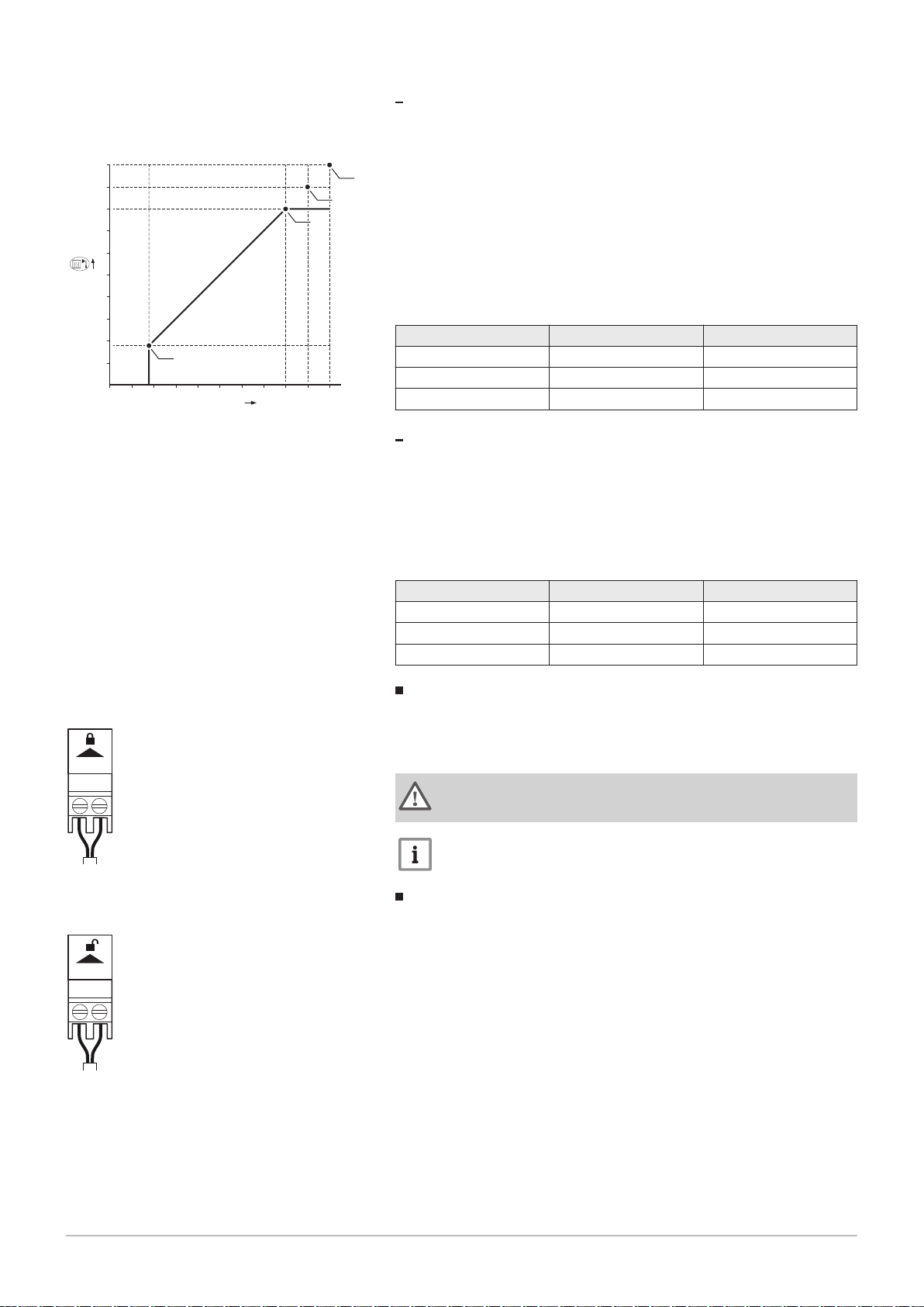
AD-0001156-02
0
1 2 3 4 5
6
7 8
9
10
0 - 10 V
10
20
30
40
50
60
70
80
90
100
2
3
4
1
AD-3000972-02
BL
AD-3001303-01
RL
6 Installation
42 7665063 - v.05 - 18102018
Analogue temperature regulation (°C)
Fig.45
Temperature regulation
1 Boiler on
2 Parameter CP010
3 Maximum flow temperature
4 Calculated value
The 0–10 V signal controls the boiler supply temperature. This control
modulates on the basis of flow temperature. The output varies between
the minimum and maximum value on the basis of the flow temperature set
point calculated by the controller.
Tab.28 Temperature regulation
Input signal (V) Temperature °C Description
0–1.5 0–15 Boiler off
1.5–1.8 15–18 Hysteresis
1.8–10 18–100 Desired temperature
Analogue output-based control
The 0 - 10 V signal controls the boiler output. This control modulates on
the basis of the heat output. The minimum output is linked to the boiler's
modulation depth. The output varies between the minimum and maximum
value on the basis of the value defined by the controller.
Tab.29 Control based on heat output
Input signal (V) Heat output (%) Description
0–2.0 0 Boiler off
2.0–2.2 0 Heat demand
2.0–10 0–100 Desired heat output
Fig.46 Blocking input
Fig.47 Release input
Blocking input
The boiler has a blocking input. This input is installed on the BL terminals
of the connector.
Change the function of the input using parameter AP001.
Warning
Only suitable for potential-free contacts.
Important
First remove the bridge if this input is used.
Release input
The boiler has a release input. This input relates to the RL terminals of the
connector.
Change the function of the input using parameter AP008.

Fig.48 Connecting an interface connector
AD-0001177-01
3
4
5
1
2
7665063 - v.05 - 18102018 43
6 Installation
Warning
Only suitable for potential-free contacts.
Connecting a PC/laptop
There is a Service connector next to the control panel. A Recom interface
can be used to connect a PC, laptop or a Smart Service Tool here. Using
the Recom PC/laptop service software, you can enter, change and read
out various boiler settings.
Connecting an interface connector:
1. Move the Service connector slide upwards.
2. Push the interface connector into place. It should snap shut with a
click.
Disconnect the interface connector again:
3. Maintain slight tension on the interface connector
4. Push the slide downwards. The interface connector will now be
released.
5. Pull the interface connector from the connector.
6.7
Filling the installation
6.7.1
In many cases, the boiler and central heating system can be filled with
normal tap water and water treatment will not be necessary.
6.7.2
The siphon is supplied separately with the boiler as standard (including a
flexible plastic drain hose). Fit the siphon under the boiler.
Water treatment
Warning
Do not add chemical agents to the central heating water without
consulting Remeha. For example: antifreeze, water softeners, pHincreasing or lowering agents, chemical additives and/or inhibitors.
Such agents can cause errors in the boiler and damage to the
heat exchanger.
Filling the siphon

AD-4100153-01
4
1
2
3
6 Installation
44 7665063 - v.05 - 18102018
Fig.49 Fill the siphon
1. Fill the siphon with water up to the mark.
2. Push the siphon firmly into the designated opening behind the
cover underneath the boiler and connect the siphon hose.
3. Push the retainer clip of the siphon forwards.
4. Check whether the siphon is firmly fitted in the boiler.
Danger
The siphon must always be sufficiently filled with water. This
prevents flue gases from entering the room.
6.7.3 Filling the system
Important
In order to be able to read off the water pressure from the control
panel, the boiler must be switched on. If the water pressure is too
low, the boiler or the boiler pump will not start.
1. Fill the central heating system with clean tap water.
Important
The recommended water pressure is between 1.5 and 2 bar.
2. Check the water-side connections for tightness.

7 Commissioning
AD-0001178-01
7665063 - v.05 - 18102018 45
7.1 Checklist before commissioning
7 Commissioning
7.1.1 Preparing the boiler for commissioning
Procedure to prepare the boiler for commissioning
1. Check the gas circuit.
2. Check the hydraulic circuit.
3. Check the water pressure in the central heating installation.
4. Check the electrical connections of the thermostat and the other
external connections.
5. Check the other connections.
6. Test the boiler at full load. Check the setting of the gas/air ratio.
7. Test the boiler at part load. Check the setting of the gas/air ratio.
8. Final activities.
Important
Complete the checklist.
Fig.50 Gas measuring point
7.1.2
1. Open the main gas tap.
2. Open the boiler gas tap.
3. Check the gas inlet pressure at the measuring point on the gas pipe.
4. Vent the gas supply pipe by unscrewing the measuring point.
5. Tighten the measuring point again when the pipe has been fully
6. Check all connections for gas tightness. The maximum allowable test
7.1.3
1. Check the siphon; it should be fully filled with clean water.
2. Check the water-side connections for tightness.
Gas circuit
Warning
Ensure that the boiler is disconnected from the power supply.
vented.
pressure is 60 mbar.
For more information, see
Unit categories, page 13
Hydraulic circuit
7.1.4 Electrical connections
1. Check the electrical connections.
7.2
Commissioning procedure
Warning
Initial commissioning must be done by a qualified professional.
1. Open the main gas tap.
2. Open the boiler gas tap.
3. Switch the power on with the boiler's on/off switch.
The start-up program will start and cannot be interrupted. During the
start-up cycle, all segments of the display are shown briefly.

AD-4100151-01
AD-4100149-01
AD-4100150-01
AD-4100148-01
7 Commissioning
46 7665063 - v.05 - 18102018
Fig.51
Fig.52
Fig.53
Fig.54
7.3 Gas settings
4. At the end of the start-up program, the display will show: : (FR
flashes in the picture)
5. With the key select the desired language.
6. Press the key to confirm the selection.
will be displayed.
7. To confirm, press the key.
8. The selected language is now set-up and the main display will appear.
9. Set the components (thermostats, control) so that heat is demanded.
Error during start-up procedure:
In the event of a fault, a message with the corresponding code is
displayed.
The meaning of the error codes can be found in the error table.
7.3.1 Adjusting to a different gas type
Warning
Only a qualified engineer may carry out the following operations.
The factory setting of the boiler is for operation with the natural gas group
G20 (H gas).
Tab.30 Factory settings G20 (H gas)
Code Description Adjustment range 160 200 250 300
DP003 Maximum fan speed on Domestic Hot
Water
GP007 Maximum fan speed during Central Heating
mode
GP008 Minimum fan speed during Central Heating
+ Domestic Hot Water mode
GP009 Fan speed at appliance start 900 Rpm - 5000 Rpm 2200 2200 2200 2200
Before operating with a different type of gas, carry out the following steps:
1000 Rpm - 7000 Rpm 6700 4650 5700 5800
1000 Rpm - 8500 Rpm 6700 4650 5700 5800
900 Rpm - 8500 Rpm 1900 1450 1550 1650
1. Fit the gas diaphragm in the gas valve unit if the boiler is modified for
G30/G31 (butane/propane):
Tab.31 Gas diaphragm for G30/G31 (butane/propane)
Gas diaphragm for G30/G31 (butane/propane) Ø (mm)
Gas 220 Ace 160 9.0
Gas 220 Ace 200 12.0
Gas 220 Ace 250 12.0
Gas 220 Ace 300 14.0

AD-0001179-01
MW-3000325-01
MW-3000326-01
7 Commissioning
7665063 - v.05 - 18102018 47
2. Adjust the fan speed (if necessary) for the gas type used according to
the table below. The setting can be changed with a parameter setting.
Tab.32 Adjustment for gas type G30/G31 (butane/propane)
Code Description Adjustment range 160 200 250 300
DP003 Maximum fan speed on Domestic Hot
1000 Rpm - 7000 Rpm 6400 4400 5400 5550
Water
GP007 Maximum fan speed during Central Heating
1000 Rpm - 8500 Rpm 6400 4400 5400 5550
mode
GP008 Minimum fan speed during Central Heating
900 Rpm - 8500 Rpm 2150 1400 1550 1700
+ Domestic Hot Water mode
GP009 Fan speed at appliance start 900 Rpm - 5000 Rpm 3000 2200 2200 2200
3. Check the setting of the gas/air ratio.
See
Checking/setting combustion, page 47
Fig.55 Flue gas measuring point
Fig.56 Step 1
7.3.2
Checking/setting combustion
1. Unscrew the cap from the flue gas measuring point.
2. Insert the probe for the flue gas analyser into the measurement
opening.
Important
During measurement, seal the opening around the sensor fully.
The flue gas analyser must have a minimum accuracy of
±0.25% O2/CO2.
3. Measure the percentage of O2/CO2 in the flue gases. Take
measurements at full load and at part load.
Enable full load
1. Press the two keys on the left simultaneously to select chimney sweep
mode.
The device is now running at part load. Wait until L:XX° appears on
the display.
Fig.57 Step 2
2. Press the key twice.
The device is now running at full load. Wait until H:XX° appears on
the display.
Checking/setting values for O2/CO2 at full load
1. Measure the percentage of O2/CO2 in the flue gases.
2. Compare the measured value with the checking values in the table.
Tab.33 Checking/setting values for O2/CO2 at full load for G20 (H
gas)
Values at full load for G20 (H gas)
Gas 220 Ace 160 4.8 - 5.2
Gas 220 Ace 200 4.8 - 5.2
O2 %
(1)
(1)
(1)
CO2 %
(1)
8.8
(1)
8.8
- 9.0
- 9.0

AD-0001327-02
2
1
A
2
A
1
MW-3000325-01
7 Commissioning
48 7665063 - v.05 - 18102018
Fig.58
Position of adjusting screw A
Values at full load for G20 (H gas)
Gas 220 Ace 250 4.8 - 5.2
Gas 220 Ace 300 4.8 - 5.2
(1) nominal value
O2 %
(1)
CO2 %
(1)
(1)
8.8
8.8
(1)
(1)
- 9.0
- 9.0
Tab.34 Checking/setting values for O2/CO2 at full load for G30/G31
(butane/propane)
Values at full load for G30/G31 (butane/
O2 %
(1)
CO2 %
propane)
Gas 220 Ace 160 5.1 - 5.4
Gas 220 Ace 200 5.2 - 5.5
Gas 220 Ace 250 5.2 - 5.5
Gas 220 Ace 300 5.2 - 5.5
(1) nominal value
(1)
(1)
(1)
(1)
10.2
10.1
10.1
10.1
(1)
- 10.4
(1)
- 10.3
(1)
- 10.3
(1)
- 10.3
Caution
The O2 values at full load must be lower than the O2 values at
low load.
The CO2 values at full load must be higher than the CO2 values
at low load.
3. If the measured value is outside of the values given in the table,
correct the gas/air ratio.
4. Using the adjusting screw A, set the percentage of O2/CO2 for the gas
type being used to the nominal value. This should always be inside
the highest and lowest setting limit.
Important
The boilers are supplied with a variety of gas valve units.
Compare the gas valve unit in the boiler with those in the drawings
and see the drawing for the position of adjusting screw A for full
load.
Enable part load
Fig.59 Step 1
1. Press the two keys on the left simultaneously to select chimney sweep
mode.
The device is now running at part load. Wait until L:XX° appears on
the display.
2. Press the h key to go back to the main display.

AD-0001326-02
2
1
B
2
B
1
7 Commissioning
7665063 - v.05 - 18102018 49
Checking/setting values for O2/CO2 at low load
1. Measure the percentage of O2/CO2 in the flue gases.
2. Compare the measured value with the checking values in the table.
Tab.35 Checking/setting values for O2/CO2 at low load for G20 (H
gas)
Values at low load for G20 (H gas)
Gas 220 Ace 160 5.2
Gas 220 Ace 200 5.2
Gas 220 Ace 250 5.2
Gas 220 Ace 300 5.2
(1) nominal value
Tab.36 Checking/setting values for O2/CO2 at low load for G30/G31
(butane/propane)
Values at low load for G30/31 (butane/
propane)
Gas 220 Ace 160 5.4
Gas 220 Ace 200 5.5
Gas 220 Ace 250 5.5
Gas 220 Ace 300 5.5
(1) nominal value
(1)
O2 %
(1)
- 5.6 8.6 - 8.8
(1)
- 5.6 8.6 - 8.8
(1)
- 5.6 8.6 - 8.8
(1)
- 5.6 8.6 - 8.8
(1)
O2 %
(1)
- 5.7 10.0 - 10.2
(1)
- 5.8 9.9 - 10.1
(1)
- 5.8 9.9 - 10.1
(1)
- 5.8 9.9 - 10.1
CO2 %
CO2 %
(1)
(1)
(1)
(1)
(1)
(1)
(1)
(1)
Caution
The O2 values at low load must be higher than the O2 values at
full load.
The CO2 values at low load must be lower than the CO2 values
at full load.
Fig.60
Position of adjusting screw B
3. If the measured value is outside of the values given in the table,
correct the gas/air ratio.
Important
The boilers are supplied with a variety of gas valve units.
Compare the gas valve unit in the boiler with those in the drawings
and see the drawing for the position of adjusting screw B for low
load.
4. Using the adjusting screw B, set the percentage of O2/CO2 for the gas
type being used to the nominal value. This should always be within
the maximum and the minimum setting limits.
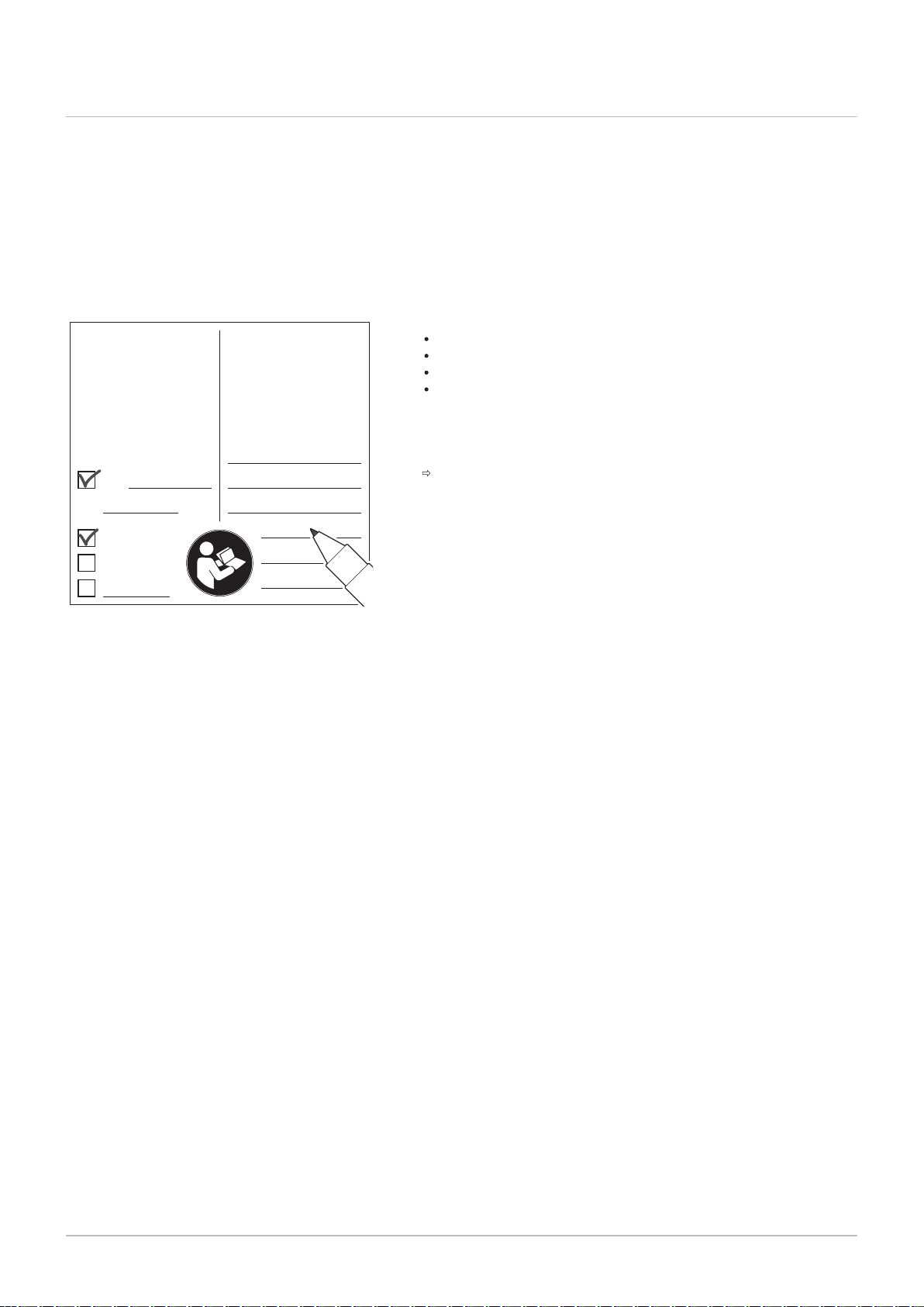
AD-3001124-01
Adjusted for / Réglée pour /
Ingesteld op / Eingestellt auf
/ Regolato per / Ajustado
para / Ρυθμισμένο για /
Nastawiony na / настроен
для / Reglat pentru /
настроен за / ayarlanmıştır /
Nastavljen za / beállítva/
Nastaveno pro / Asetettu
kaasulle / Justert for/
indstillet til/ ضبط ل :
C
(10)3(X)
Gas
C
(12)3(X)
mbar
Parameters / Paramètres /
Parameter / Parametri /
Parámetros / Παράμετροι /
Parametry / Параметры /
Parametrii / Параметри /
Parametreler / Paraméterek
/ Parametrit / Parametere /
Parametre / المعلمات :
G20
20
DP003 - 3300
GP007 - 3300
GP008 - 2150
GP009 -
7 Commissioning
50 7665063 - v.05 - 18102018
7.4 Final instructions
Fig.61
Example filled-in sticker
1. Remove the measuring equipment.
2. Screw the cap on to the flue gas measuring point.
3. Seal the gas valve unit.
4. Put the front casing back.
5. Heat the central heating system up to approximately 70°C.
6. Switch the boiler off.
7. Vent the central heating system after approx. 10 minutes.
8. Turn on the boiler.
9. Check the water pressure. If necessary, top up the central heating
system.
10. Fill in the following data on the sticker included, and attach it next to
the data plate on the appliance.
If adapted to another gas, fill in the gas type;
The gas supply pressure;
If set to overpressure application, fill in the type;
The parameters modified for the changes mentioned above.
11. Instruct the user in the operation of the system, boiler and controller.
12. Inform the user of the maintenance to be performed.
13. Hand over all manuals to the user.
14. Confirm the commissioning with a signature and a company stamp.
The boiler is now ready for operation.

8 Operation
7665063 - v.05 - 18102018 51
8.1 Use of the control panel
8 Operation
The display on the control panel provides information about the operating
status of the boiler and any errors.
See
The control panel manual for extra information about:
Changing, creating and resetting settings.
Reading out values.
Functions of the panel.
Clearing the error memory.
8.2
Shutdown
8.3 Frost protection
If the central heating is not due to be used for a long period of time, it is
recommended that the boiler be disconnected from the power supply.
1. Turn off the boiler using the on/off switch.
2. Shut off the gas supply.
3. Keep the area frost-free.
Caution
Drain the boiler and central heating system if you are not going
to use your home or the building for a long time and there is a
chance of frost.
The frost protection does not work if the boiler is out of
operation.
The built-in boiler protection is only activated for the boiler and
not for the system and radiators.
Open the valves of all the radiators connected to the system.
Set the temperature control low, for example to 10°C.
If there is no heat demand, the boiler will only switch on to protect itself
against frost.
If the temperature of the central heating water in the boiler drops too low,
the built-in boiler protection system is activated. This system works as
follows:
At a water temperature lower than 7°C, the heating pump starts.
If the water temperature is lower than 4°C, the boiler switches on.
If the water temperature is higher than 10℃ the boiler switches off and
the circulation pump continues to run for a short time.
To prevent the system and radiators freezing in frost-sensitive areas (e.g.
a garage), a frost thermostat or outside sensor can be connected to the
boiler.

9 Settings
52 7665063 - v.05 - 18102018
9 Settings
9.1 List of parameters
The code of the parameters always contain two letters and three numbers.
The letters stand for:
AP Appliance related parameters
CP Zone related parameters
DP Domestic hot water related parameters
EP Smart Solutions related parameters
GP Gas-fired heat engine related parameters
PP Central heating related parameters
Important
All possible options are indicated in the adjustment range. The
display of the boiler only shows the relevant settings for the
appliance.
9.1.1 Parameters - FSB-WHB-HE-150-300
Important
All tables show the factory setting for the parameters.
The tables also list parameters that are only applicable if the
boiler is combined with other equipment such as an outdoor
sensor.
All possible options are indicated in the adjustment range. The
display of the boiler only shows the relevant settings for the
appliance.
Tab.37
Code Description Range 160 200 250 300
AP016 Enable central heating heat demand
AP017 Enable domestic hot water heat
CP080 Room setpoint temperature of the
CP081 Room setpoint temperature of the
CP082 Room setpoint temperature of the
CP083 Room setpoint temperature of the
CP084 Room setpoint temperature of the
CP085 Room setpoint temperature of the
CP200 Manually setting the room
CP320 Operating mode of the zone 0 = Scheduling
CP510 Temporary room setpoint per zone 5 °C - 50 °C 20 20 20 20
CP550 Fire Place mode is active 0 = Off
> FSB-WHB-HE-150-300 - Factory settings at user level
0 = Off
processing
demand processing
user zone activity
user zone activity
user zone activity
user zone activity
user zone activity
user zone activity
temperature setpoint of the zone
1 = On
0 = Off
1 = On
5 °C - 30 °C 16 16 16 16
5 °C - 30 °C 20 20 20 20
5 °C - 30 °C 6 6 6 6
5 °C - 30 °C 21 21 21 21
5 °C - 30 °C 22 22 22 22
5 °C - 30 °C 20 20 20 20
5 °C - 30 °C 20 20 20 20
1 = Manual
2 = Antifrost
3 = Temporary
1 = On
1 1 1 1
1 1 1 1
1 1 1 1
0 0 0 0

Code Description Range 160 200 250 300
7665063 - v.05 - 18102018 53
CP570 Time Program of the zone selected
by the user
0 = Schedule 1
1 = Schedule 2
0 0 0 0
2 = Schedule 3
3 = Cooling
CP660 Choice icon to display this zone 0 = None
1 1 1 1
1 = All
2 = Bedroom
3 = Livingroom
4 = Study
5 = Outdoor
6 = Kitchen
7 = Basement
8 = Swimming Pool
9 = DHW Tank
10 = DHW Electrical
Tank
11 = DHW Layered
Tank
12 = Internal Boiler
Tank
13 = Time Program
CP670 Configuration of pairing room unit
- - - -
per zone
9 Settings
Tab.38
> FSB-WHB-HE-150-300 - Factory settings at installer level
Code Description Range 160 200 250 300
AP001 Blocking input setting (1: Full
blocking, 2: Partial blocking, 3: User
reset locking)
1 = Full blocking
2 = Partial blocking
3 = User reset locking
1 1 1 1
4 = Backup Relieved
5 = Heat Pump
Relieved
6 = HP & backup
relieved
7 = High, Low Tariff
8 = Photovoltaic HP
Only
9 = PV HP And backup
10 = Smart Grid ready
11 = Heating Cooling
AP006 Appliance will report low water
0 bar - 6 bar 0,7 0,7 0,7 0,7
pressure below this value
AP008 The appliance will wait x sec (0=off)
0 Sec - 255 Sec 0 0 0 0
for the release contact to close in
order to start the burner
AP009 Burning hours before raising a
service notification
AP010 The type of service needed based
on burn and powered hours
100 Hours - 25500
Hours
0 = None
1 = Custom notification
17400 17400 17400 17400
2 2 2 2
2 = ABC notification
AP011 Hours powered to raise a service
notification
AP056 Enable outdoor sensor 0 = No outside sensor
100 Hours - 25500
Hours
17400 17400 17400 17400
1 1 1 1
1 = AF60
2 = QAC34
AP073 Outdoor temperature: upper limit for
1.5 °C - 60 °C 22 22 22 22
heating
AP074 The heating is stopped. Hot water is
maintained. Force Summer Mode
0 = Off
1 = On
0 0 0 0
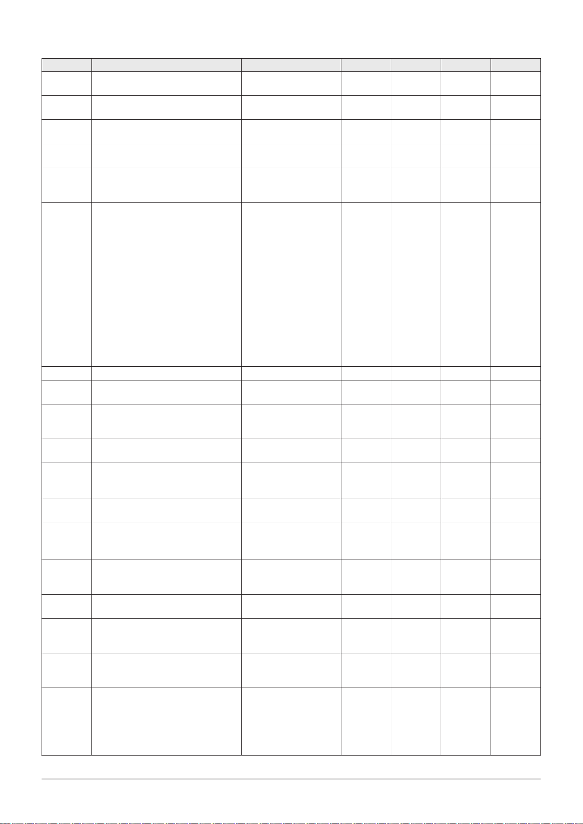
9 Settings
54 7665063 - v.05 - 18102018
Code Description Range 160 200 250 300
AP079 Inertia of the building used for heat
0 - 255 0 0 0 0
up speed
AP080 Outside temperature below which
-32 °C - 10 °C 0 0 0 0
the antifreeze protection is activated
AP110 Parameter to activate the 2nd return
sensor
CP000 Maximum Flow Temperature
0 = Inactive
0 0 0 0
1 = Active
0 °C - 90 °C 90 90 90 90
setpoint zone
CP010 Zone flow temperature setpoint,
0 °C - 90 °C 90 90 90 90
used when the zone is set to a fixed
flow setpoint.
CP020 Functionality of the zone 0 = Disable
1 1 1 1
1 = Direct
2 = Mixing Circuit
3 = Swimming pool
4 = High Temperature
5 = Fan Convector
6 = DHW tank
7 = Electrical DHW
8 = Time Program
9 = ProcessHeat
10 = DHW Layered
11 = DHW Internal tank
12 = DHW Commercial
Tank
31 = DHW FWS EXT
CP040 Pump post runtime of the zone 0 Min - 20 Min 0 0 0 0
CP060 Wished room zone temperature on
5 °C - 20 °C 6 6 6 6
holiday period
CP070 Max Room Temperature limit of the
5 °C - 30 °C 15 15 15 15
circuit in reduced mode, that allows
switching to comfort mode
CP210 Comfort footpoint of the temperature
15 °C - 90 °C 15 15 15 15
of heat curve of the circuit
CP220 Reduced footpoint of the
15 °C - 90 °C 15 15 15 15
temperature of heat curve of the
circuit
CP230 Heating curve temperature gradient
0 - 4 2,5 2,5 2,5 2,5
of the zone
CP240 Adjustment of the influence of the
0 - 10 3 3 3 3
zone room unit
CP250 Calibration of Zone Room Unit -5 °C - 5 °C 0 0 0 0
CP340 Type of reduced night mode, stop or
maintain heating of circuit
0 = Stop heat demand
1 = Continue heat
0 0 0 0
demand
CP470 Setting of the screed drying program
0 Days - 30 Days 0 0 0 0
of the zone
CP480 Setting of the start temperature of
20 °C - 50 °C 20 20 20 20
the screed drying program of the
zone
CP490 Setting of the stop temperature of
20 °C - 50 °C 20 20 20 20
the screed drying program of the
zone
CP730 Selection of heat up speed of the
zone
0 = Extra Slow
1 = Slowest
0 0 0 0
2 = Slower
3 = Normal
4 = Faster
5 = Fastest

MW-3000312-01
9 Settings
7665063 - v.05 - 18102018 55
Code Description Range 160 200 250 300
CP740 Selection of cool down speed of the
zone
0 = Slowest
1 = Slower
0 0 0 0
2 = Normal
3 = Faster
4 = Fastest
CP750 Maximum zone preheat time 0 Min - 65000 Min 0 0 0 0
CP780 Selection of the control strategy for
the zone
0 = Automatic
1 = Room Temp based
1 1 1 1
2 = Outdoor Temp
based
3 = Outdoor&Room
based
DP003 Maximum fan speed on Domestic
1000 Rpm - 7000 Rpm 6700 4650 5700 5800
Hot Water
EP014 Smart Control Board function 10 Volt
PWM input
0 = Off
1 = Temperature
0 0 0 0
control
2 = Power control
GP007 Maximum fan speed during Central
1000 Rpm - 8500 Rpm 6700 4650 5700 5800
Heating mode
GP008 Minimum fan speed during Central
900 Rpm - 8500 Rpm 1900 1450 1550 1650
Heating + Domestic Hot Water mode
GP009 Fan speed at appliance start 900 Rpm - 5000 Rpm 2200 2200 2200 2200
GP010 Gas Pressure Switch check on/off 0 = No
0 0 0 0
1 = Yes
GP021 Modulate back when delta
5 °C - 25 °C 25 25 25 25
temperature is large then this
treshold
GP024 Valve Proofing System check on /
off
0 = No
1 = Yes
0 0 0 0
PP015 Central heating pump post run time 1 Min - 99 Min 1 1 1 1
PP016 Maximum central heating pump
20 % - 100 % 100 100 100 100
speed (%)
PP018 Minimum central heating pump
20 % - 100 % 20 20 20 20
speed (%)
PP023 Hysteresis to start burner in heating
1 °C - 25 °C 10 10 10 10
mode
9.2
Changing the parameters
The boiler’s control unit is set for the most common central heating
systems. These settings will ensure that virtually every central heating
system operates effectively. The user or the installer can optimise the
parameters as required.
Caution
Changing the factory settings may adversely affect the operation
of the boiler.
9.2.1 Configuring the installation parameters
1. Navigate to the Installer menu.
Fig.62
Step 2
2. Press the key to open the menu.

MW-3000313-01
MW-3000314-01
MW-3000406-02
MW-3000407-01
MW-3000315-01
MW-3000336-01
MW-3000337-01
MW-3000338-01
MW-3000316-01
MW-3000320-01
9 Settings
56 7665063 - v.05 - 18102018
Fig.63
Step 3
Fig.64 Step 4
Fig.65 Step 5
Fig.66 Step 6
Fig.67 Step 7
3. Keep pressing the key until the code 0012 is displayed.
4. Press the key to confirm opening the menu.
Keep pressing the key until the required device, control PCB or
5.
zone is displayed.
6. Press the key to confirm the selection.
7. Keep pressing the or key until the required parameter is
displayed.
Fig.68 Step 8
Fig.69 Step 9
Fig.70 Step 10
Fig.71 Step 11
9.3
Reading out measured values
Fig.72 Step 2
8. Press the key to confirm the selection.
9. Press the or key to modify the value.
10. Press the key to confirm the value.
11. Press the h key multiple times to go back to the main display.
9.3.1
Reading out counters
You can read out the counters of the appliance and the connected control
boards, sensors and so on.
1. Navigate to the Counter menu.
2. Press the key to open the menu.

MW-3000422-01
MW-3000453-01
MW-3000439-01
MW-3000439-01
MW-3000441-01
MW-3000306-01
MW-3000451-01
MW-3000452-01
MW-3000307-01
MW-3000308-01
9 Settings
7665063 - v.05 - 18102018 57
Fig.73
Step 3
Fig.74 Step 4
Fig.75 Step 5
Fig.76 Step 6
Fig.77 Step 7
3. Press the key to confirm the selection.
The text CODE flashes in the display.
4. Press the key to confirm the selection.
Keep pressing the key until the code 0012 is displayed.
5.
6. Keep pressing the key until the required value is displayed.
7. Press the h key multiple times to go back to the main display.
Fig.78 Step 2
Fig.79 Step 3
Fig.80 Step 4
Fig.81 Step 5
9.3.2 Reading out signals and software versions
You can read out the signals and software versions of the appliance and
the connected control boards, sensors and so on.
1. Navigate to the Information menu.
2. Press the key to open the menu.
3. Keep pressing the key until the required device, control PCB or
zone is displayed.
4. Press the key to confirm the selection.
5. Keep pressing the or key until the required value is displayed.
At the end of the cycle, the software version and parameter version of
the selected appliance or control PCB are displayed.
Fig.82 Step 6
6. Press the h key multiple times to go back to the main display.
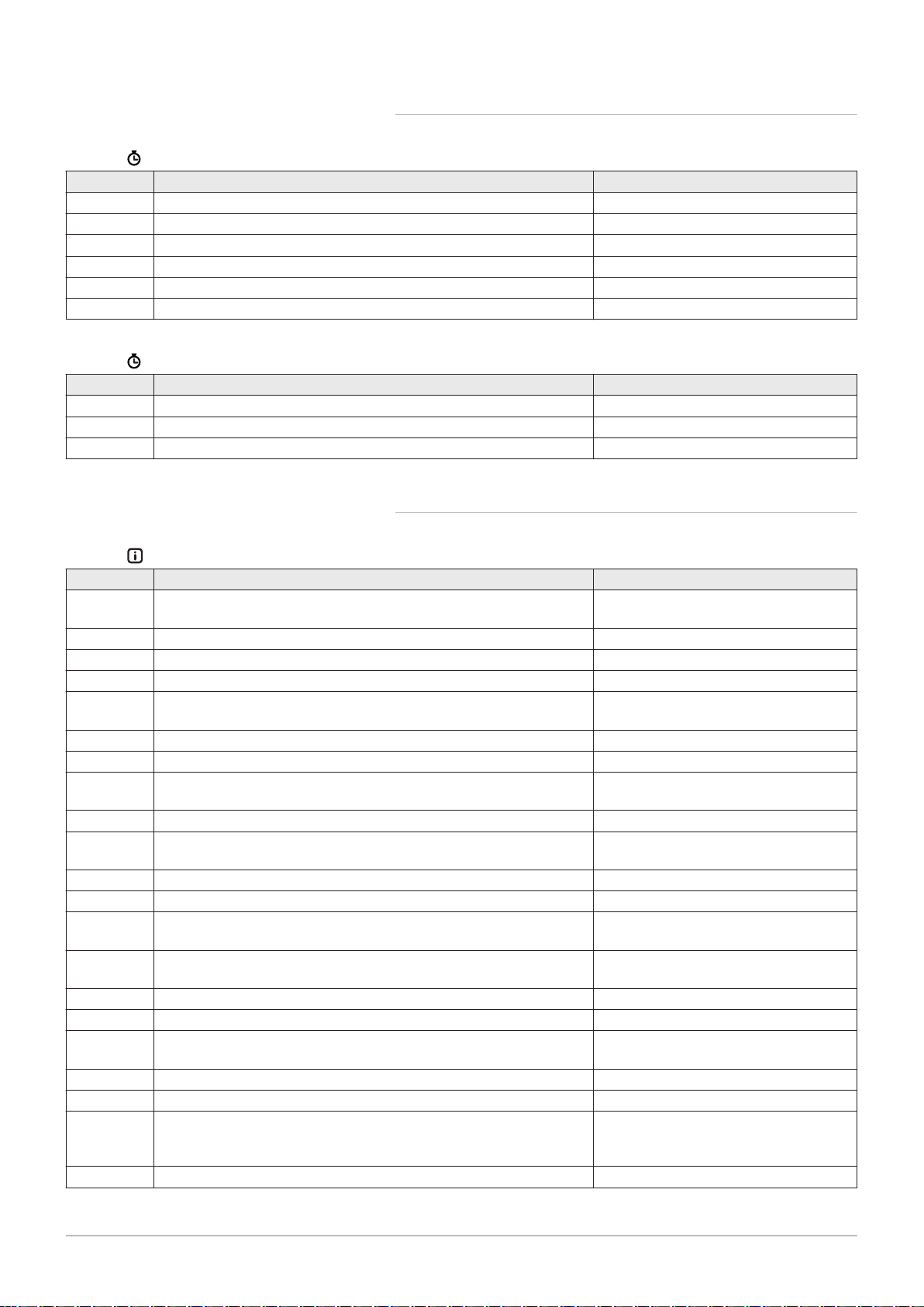
9 Settings
58 7665063 - v.05 - 18102018
9.3.3 Counters - FSB-WHB-HE-150-300
Tab.39
Code Description Range
AC001 Number of hours that the appliance has been on mains power 0 Hours - 65534 Hours
DC002 Numbers of Domestic Hot Water diverting valve cycles 0 - 4294967295
DC003 Number of hours during which the diverting valve is in DHW position 0 Hours - 4294967295 Hours
DC004 Number of burner starts for Domestic Hot Water 0 - 4294967295
DC005 Number of burning hours in Domestic Hot Water 0 Hours - 4294967295 Hours
PC003 Total number of burning hours. For heating and domestic hot water 0 Hours - 65534 Hours
Tab.40
Code Description Range
DC001 Total power consumption used by Domestic Hot Water 0 kW - 4294967295 kW
PC002 Total number of burner starts. For heating and domestic hot water 0 - 65534
PC004 Number of burner flame loss 0 - 65534
Tab.41
Code Description Range
AM001 Is the appliance currently in domestic hot water production mode? 0 = Off
AM010 The current pump speed 0 % - 100 %
AM012 Current main status of the appliance. DeviceState
AM014 Current sub status of the appliance. DeviceSubStatus
AM015 Is the pump running? 0 = Inactive
AM016 Flow temperature of appliance. -25 °C - 150 °C
AM017 The temperature of heat exchanger -25 °C - 150 °C
AM018 Return temperature of appliance. The temperature of the water
AM019 Water pressure of the primary circuit. 0 bar - 25.5 bar
AM022 On / Off heat demand 0 = Off
AM024 Actual relative power of the appliance 0 % - 655.35 %
AM027 Instantaneous outside temperature -60 °C - 60 °C
AM028 Value of the 0 to 10 Volt input. Meaning is dependant on the current
AM037 Status of the three way valve 0 = CH
AM040 Temperature used for hot water control algorithms. -25 °C - 150 °C
AM101 Internal system flow temperature setpoint 0 °C - 120 °C
AP078 Outside sensor detected in the application 0 = No
GM001 Actual fan RPM 0 Rpm - 8500 Rpm
GM002 Actual fan RPM setpoint 0 Rpm - 8500 Rpm
GM006 Gas Pressure Switch status 0 = Open
GM008 Actual flame current measured 0 µA - 25 µA
> FSB-WHB-HE-150-300 - Counters at user level
> FSB-WHB-HE-150-300 - Counters at installer level
9.3.4
> FSB-WHB-HE-150-300 - Signals at user level
entering the appliance.
input function setting.
Signals - FSB-WHB-HE-150-300
1 = On
1 = Active
-25 °C - 150 °C
1 = On
0 V - 25 V
1 = DHW
1 = Yes
1 = Closed
2 = Off

Code Description Range
7665063 - v.05 - 18102018 59
GM012 Release signal for the CU 0 = No
1 = Yes
GM015 Valve Proving System switch open / closed 0 = Open
1 = Closed
2 = Off
9 Settings
Tab.42
> FSB-WHB-HE-150-300 - Signals at installer level
Code Description Range
AM011 Is service currently required? 0 = No
1 = Yes
AM033 Next service indication 0 = None
1 = A
2 = B
3 = C
4 = Custom
AM036 Temperature of the exhaust gas leaving the appliance 0 °C - 250 °C
AM044 Number of sensors supported by the device 0 - 255
AM045 Water pressure sensor present? 0 = No
1 = Yes
AM091 Seasonal mode active (summer / winter) 0 = Winter
1 = Frost protection
2 = Summer neutral band
3 = Summer
GM004 Gas valve 1 0 = Open
1 = Closed
2 = Off
GM005 Gas valve 2 0 = Open
1 = Closed
2 = Off
GM010 Available power in % of maximum 0 % - 100 %
GM044 Possible reason for Controlled Stop 0 = None
1 = CH Blocking
2 = DHW Blocking
3 = Wait for burner
4 = TFlow > absolute max
5 = TFlow > start temp.
6 = Theat exch. > Tstart
7 = Avg Tflow > Tstart
8 = TFlow > max setpoint
9 = T difference too big
10 = TFlow > stop temp.
11 = Avg Tflow > Tstop
PM002 External winning Central Heating setpoint 0 °C - 125 °C
9.3.5 Status and sub-status - FSB-WHB-HE-150-300
Tab.43 Status numbers
Status
0 Standby
1 Heat Demand
2 Burner Start
3 Burning CH
4 Burning Dhw
5 Burner Stop
6 Pump Post Run
7 Cooling Active

9 Settings
60 7665063 - v.05 - 18102018
Status
8 Controlled Stop
9 Blocking Mode
10 Locking Mode
11 Load test min
12 Load test CH max
13 Load test DHW max
15 Manual Heat Demand
16 Frost Protection
17 DeAiration
18 Control unit Cooling
19 Reset In Progress
20 Auto Filling
21 Halted
200 Device Mode
Tab.44 Sub-status numbers
Sub-status
0 Standby
1 AntiCycling
2 CloseHydraulicValve
3 ClosePump
4 WaitingForStartCond.
10 CloseExtGasValve
11 StartToGlueGasValve
12 CloseFlueGasValve
13 FanToPrePurge
14 WaitForReleaseSignal
15 BurnerOnCommandToSu
16 VpsTest
17 PreIgnition
18 Ignition
19 FlameCheck
20 Interpurge
30 Normal Int.Setpoint
31 Limited Int.Setpoint
32 NormalPowerControl
33 GradLevel1PowerCtrl
34 GradLevel2PowerCtrl
35 GradLevel3PowerCtrl
36 ProtectFlamePwrCtrl
37 StabilizationTime
38 ColdStart
39 ChResume
40 SuRemoveBurner
41 FanToPostPurge
42 OpenExt&FlueGasValve
43 StopFanToFlueGVRpm
44 StopFan
45 LimitedPwrOnTflueGas
60 PumpPostRunning
61 OpenPump
62 OpenHydraulicValve

Sub-status
7665063 - v.05 - 18102018 61
63 SetAntiCycleTimer
200 Initialising Done
201 Initialising Csu
202 Init. Identifiers
203 Init.BL.Parameter
204 Init. Safety Unit
205 Init. Blocking
9 Settings
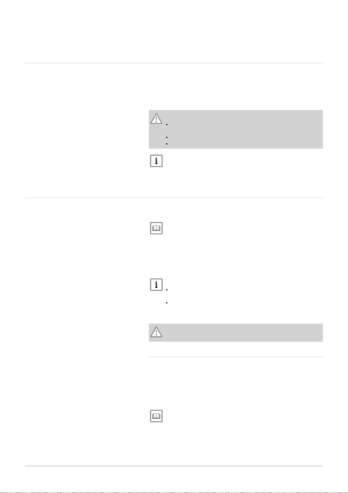
10 Maintenance
62 7665063 - v.05 - 18102018
10 Maintenance
10.1 General
The boiler does not require a lot of maintenance. Nevertheless, the boiler
must be inspected and maintained periodically. To determine the best time
for servicing, the boiler is equipped with an automatic service message.
The control unit determines when this service message appears.
Depending on boiler use, the first service message appears no later than 3
years after installation of the boiler.
Caution
Maintenance operations must be completed by a qualified
installer.
Replace defective or worn parts with original spare parts.
An annual inspection is mandatory.
Important
Adjust the frequency of inspection and service to the conditions of
use. This applies especially to boilers in constant use (for specific
processes).
10.2 Maintenance message
The boiler display will clearly indicate that a service is required at the
appropriate time.
See
Manual for the control panel
Use the automatic service message for preventive maintenance, to keep
faults to a minimum. The service messages show which service kit must
be used. These service kits contain all parts and gaskets that are required
for the relevant service. These service kits (A, B or C), put together by
Remeha , are available from your spare parts supplier.
Important
A service message must be followed up within 2 months.
Therefore, call your installer as soon as possible.
If the iSense modulating controller is connected to the boiler,
this maintenance message can also be forwarded to the iSense.
Consult the manual for the regulator.
Caution
Reset the maintenance message following every service.
10.2.1
Resetting the service messages
A service message on the boiler display must be reset by a qualified
installer within two months after the indicated maintenance service has
been carried out using the relevant service set and after this has been
entered in the checklist. Proceed as follows:
1. Perform the service with the specified service kit (A, B or C).
2. Note the service in the corresponding checklist.
See
Appendix, page 85
3. Reset the service message.

10 Maintenance
7665063 - v.05 - 18102018 63
10.2.2 Starting a new service interval
For an interim service it is advisable to read out in the boiler service menu
what maintenance service should be carried out. Use the indicated
Remeha service kits (A, B or C). This service message must be prevented
by carrying out a reset. Start the next service interval. Proceed as follows:
1. In the Service menu of the boiler, read which service should be
performed.
2. Perform the service with the specified service kit (A, B or C).
3. Note the service in the corresponding checklist.
See
Appendix, page 85
4. Reset the service message.
This prevents this service message from appearing automatically
after all.
5. Start the next service interval.
10.3
Standard inspection and maintenance operations
Warning
Always wear safety goggles and a dust mask during cleaning work
(involving compressed air).
For a service, always perform the following standard inspection and
maintenance operations.
Caution
Check whether all gaskets have been positioned properly
(absolutely flat in the appropriate groove means they are gas
tight).
During the inspection and maintenance operations, water
(drops, splashes) must never come into contact with the
electrical parts.
10.3.1 Checking the water pressure
1. Check the water pressure.
Important
The water pressure is shown on the display of the control panel.
The water pressure must be at least 0.8 bar
2. If the water pressure is lower than 0.8 bar, top up the central heating
system.
10.3.2
1. Fill a clean bottle with some water from the system/boiler from the
2. Check the quality of this water sample or have it checked.
Checking the water quality
filling and drain cock.
See
More information is available in our Water quality instructions. This
manual forms part of the set of documents supplied with the
boiler. Always adhere to the instructions in the aforementioned
document.
10.3.3 Checking the ionisation current
1. Check the ionisation current at full load and at low load.
The value is stable after 1 minute.
2. Clean or replace the ionisation/ignition electrode if the value is less
than 4 µA.

AD-0001181-01
SLOW
(+)
7
3
5
X mbar
........ mb
ar
5,5 mbar.... 6,5
8
P
1
(+)
P
2
(-)
2
9
4
1 6
10 Maintenance
64 7665063 - v.05 - 18102018
For more information, see
Replacing the ionisation/ignition electrode, page 71
Fig.83 Check the air pressure differential
switch + side
10.3.4
Check the flue gas outlet/air supply connections
1. Check the flue gas outlet and air supply connections for condition and
tightness.
10.3.5 Checking the combustion
Combustion is checked by measuring the O2/CO2percentage in the flue
gas outlet duct.
10.3.6 Checking the PS air pressure differential switch
Checking the air pressure differential switch + side
1. Switch off the boiler.
2. Disconnect the silicon hose on the + side (P1) of the air pressure
differential switch.
3. Take a large plastic syringe or bellows and connect a T piece with a
hose connected.
4. Connect the + side of the air pressure differential switch to one end of
the T piece with a hose.
5. On the other end of the T piece, connect the + side of a pressure
gauge.
6. Turn on the boiler
7. Push the syringe or bellows in very slowly until the boiler goes into
failure mode.
8. Make a note of the pressure indicated by the pressure gauge at that
point. A switch pressure of between 5.5 and 6.5 mbar is fine. A lower
or higher switch pressure indicates a problem with the air pressure
differential switch.
9. After taking a measurement, detach the silicon hose from the T piece
on the + side and reconnect the hose that was previously removed.
Caution
Please note: The + side (P1) is the rear connector nipple of the air
pressure differential switch.
10. Remove any soiling from all connection points for hoses and the air
pressure differential switch.
11. Check the condition and tightness of the hoses of the air pressure
differential switch. Replace the hoses if necessary.

Checking the air pressure differential switch – side
AD-0001076-01
SLOW
3
X mbar
........ mb
ar
4
-5.5 mbar....-6,5
(+)
P
1
(+)
1
2
P
2
(-)
7665063 - v.05 - 18102018 65
10 Maintenance
Fig.84
– side of the air pressure differential
switch
1. Disconnect the short, dark-coloured silicon hose on the – side (P2) of
the air pressure differential switch.
2. Connect the – side of the air pressure differential switch to one end of
the T piece with a hose.
3. Pull out the syringe until the boiler goes into failure mode.
4. Make a note of the pressure indicated by the pressure gauge at that
point.
A switch pressure of between - 5.5 and - 6.5 mbar is fine. A lower or
higher switch pressure indicates a problem with the air pressure
differential switch.
5. After taking a measurement, detach the silicon hose from the T-piece
on the – side and reconnect the coloured hose that was previously
removed.
6. Remove any soiling from all connection points for hoses and the air
pressure differential switch.
7. Check the condition and tightness of the hoses of the air pressure
differential switch.
Replace the hoses if necessary.

AD-0001182-01
SLOW
(+)
X mbar
30 sec
≥ 0.5 x
≤ 0.5 x
1
2
6
8 10
9
7
5
3
4
P1
P2
P2
10 Maintenance
66 7665063 - v.05 - 18102018
10.3.7 Checking the VPS gas leakage control
Checking the VPS for leaks
Fig.85
Checking the VPS for leaks
1. Switch off the boiler.
2. Close the boiler gas tap.
3. Remove the pressure from the gas pipe by unscrewing the screw in
measuring point P1.
4. As soon as the gas pipe is pressure-free, re-tighten the screw.
5. Open the screw at measuring point P2 on the gas valve unit (on the
other side of the VPS pressure switch).
6. Take a large plastic syringe and connect a T piece with a hose
connected to the mouth.
7. Connect one end of the T piece to measuring point 3 of the gas valve
unit.
8. Connect the other end of the T piece to a pressure gauge.
9. Push the syringe in very slowly until the pressure gauge indicates the
minimum inlet gas pressure value.
10. Check the measured pressure for about 30 seconds. If pressure
decreases by more than half, this indicates a gas leak.
11. Replace the gas valve unit or the VPS if necessary.

Checking the VPS switch value
AD-0001183-01
SLOW
10 sec
0 Ohm
(+)
X mbar
4
5 5
3.23.1
3
2
21
........ mb
ar
6
P2
P2
P2
7665063 - v.05 - 18102018 67
10 Maintenance
Fig.86
Checking the VPS switch value
1. Remove the pressure from the gas valve unit; first remove the hose
that is attached to measuring point 3 of the gas valve unit (on the
other side of the VPS pressure switch).
2. Wait approximately 10 seconds and reconnect the disconnected hose
to measuring point P2 of the gas valve unit.
3. Remove the connecting plug from the VPS gas leakage control.
4. Connect an ohmmeter to terminals 2 and 3 of the VPS.
5. Push the syringe in very slowly until the ohmmeter indicates 0 Ohm.
6. Make a note of the pressure indicated by the pressure gauge at that
point. If the measured pressure differs by more than 2 mbar from the
VPS set-up value, set the pressure switch to the correct value or
replace it.

AD-0001184-01
1
5
(+)
X mbar
........ mb
ar
≤ 10.0
3
4
6
P2
10 Maintenance
68 7665063 - v.05 - 18102018
10.3.8 Checking the minimum gas pressure switch GPS
Fig.87 Checking the GPS
1. Switch off the boiler.
2. Open the screw in measuring point 2 of the gas valve unit.
3. Connect a pressure gauge to measuring point 2 of the gas valve unit.
4. Turn on the boiler.
5. Set the boiler to low load.
6. Close the boiler gas tap very slowly until the boiler goes into blocking
mode.
7. Make a note of the pressure indicated by the pressure gauge at that
point. Compare the measured values with the checking values in the
table. If the measured pressure is lower, set the gas pressure switch
to the correct value or replace it.
Tab.45 Minimum gas pressure switch value
Minimum value (mbar)
Gas 220 Ace 160 14
Gas 220 Ace 200 14
Gas 220 Ace 250 14
Gas 220 Ace 300 13

AD-0001185-01
9
11
7 3x
6
8
12
10
1
2
3
5
3x
4
3x
10 Maintenance
7665063 - v.05 - 18102018 69
10.3.9 Checking the burner and cleaning the heat exchanger
Fig.88 Checking the burner
1. Disconnect the plug of the ionisation/ignition electrode from the
ignition transformer.
Caution
The ignition cable is fixed to the ionisation/ignition electrode and
therefore may not be removed.
2. Loosen the 2 screws of the ionisation/ignition electrode.
3. Remove the ionisation/ignition electrode with the seal from the heat
exchanger.
4. Undo the 3 bolts from the adapter on the non-return valve holder (15
Nm torque).
5. Undo the 3 nuts from the adapter on the heat exchanger (15 Nm
torque).
6. Carefully remove the adapter with burner from the heat exchanger.
7. Remove the 3 bolts from the burner on the adapter and dismantle the
burner and seal.
8. Undo the nuts on the inspection ports (7.5 Nm torque).
Remove the inspection ports to reach the heat exchanger.
9. Use a vacuum cleaner to clean the top part of the heat exchanger
(furnace).
10. Check (e.g. using a mirror) whether any visible contamination has
been left behind. If it has, remove it with the vacuum cleaner.
11. Clean the lower section of the heat exchanger with the special
cleaning knife.
12. Burner maintenance is almost never required; it is self-cleaning:
12.1. If necessary, carefully clean the cylinder-shaped burner with
compressed air.
12.2. Check that the burner cover of the dismantled burner is free
from cracks and/or damage. If not, replace the burner.
13. Reassemble the unit in the reverse order.
14. Open the gas supply and insert the plug in the socket again.
Caution
Use the specified torques when fitting nuts and bolts.
Make sure the gaskets are in place when fitting nuts and bolts.

AD-0001186-02
2
3
1
AD-4100152-01
1
2
3
75 6
4
10 Maintenance
70 7665063 - v.05 - 18102018
10.3.10 Clean the condensate collector
Fig.89 Clean the condensate collector
Fig.90 Cleaning the siphon
1. Remove the air intake silencer.
2. Remove the sealing cap from the condensate collector.
3. Rinse the condensate collector thoroughly with a water flow that is as
large as possible.
Warning
When flushing, prevent water from getting into the boiler.
4. Disconnect the silicon hose of the air pressure differential switch from
the connection nipple on the condensate collector.
5. Clean the opening of the connection nipple thoroughly (by blowing air
or pushing an object through it).
6. Reconnect the silicon hose.
7. Put the air intake silencer and the sealing cap back on the condensate
collector.
10.3.11 Cleaning the siphon
1. Pull the retainer clip of the siphon backwards.
2. Carefully pull the siphon and siphon hose downwards.
3. Clean the siphon with water.
4. Fill the siphon with water up to the mark.
5. Push the siphon firmly into the designated opening behind the
cover underneath the boiler and install the siphon hose.
6. Push the retainer clip of the siphon forwards.
7. Check whether the siphon is firmly fitted in the boiler.
10.4 Specific maintenance work
Danger
The siphon must always be filled with water. This prevents flue
gases from entering the room.
Perform the specific maintenance work if this proves to be necessary
following the standard inspection and maintenance work. To conduct the
specific maintenance work:

10.4.1 Replacing the ionisation/ignition electrode
AD-0001187-01
1
2
3
4
7665063 - v.05 - 18102018 71
10 Maintenance
Fig.91 Replacing the ionisation/ignition
electrode
The ionisation/ignition electrode must be replaced if:
The ionisation current is < 4 µA.
The electrode is damaged or worn.
The electrode is included in the service kit.
1. Remove the plug of the electrode from the ignition transformer.
Important
The ignition cable is fixed to the electrode and therefore may not
be removed.
2. Unscrew the two screws on the electrode.
3. Remove the entire component.
4. Fit the new ionisation/ignition electrode.
5. Reassemble the unit in reverse order.
10.4.2
Checking the non-return valve
Check the condition of the non-return valve. Replace the non-return valve
if it is defective, there is one in the service kit, or if there are traces of
condensation on the inside of the fan. Do this as follows:
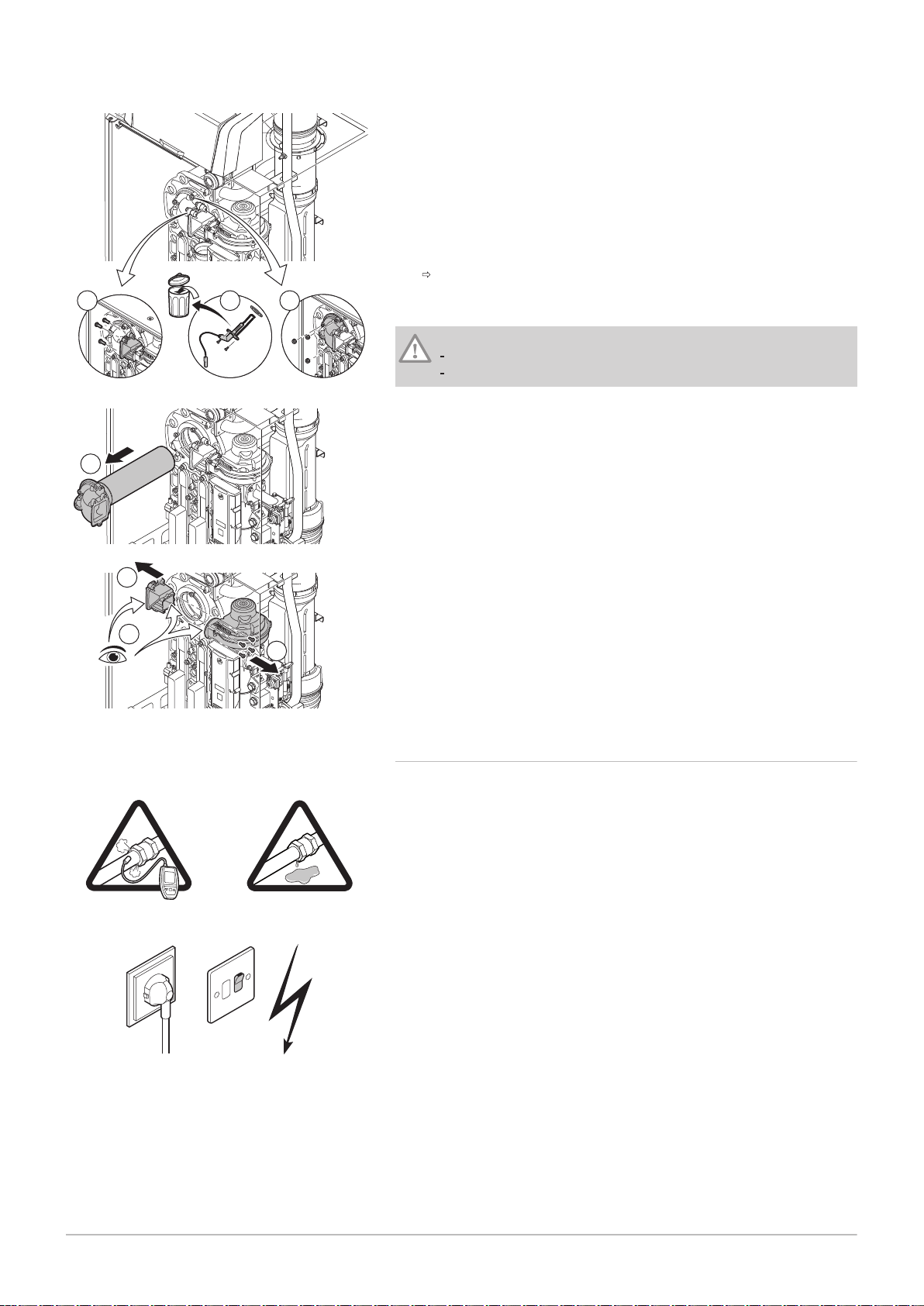
AD-0001188-01
1
4
4
5
3
6
2
AD-0000132-01
Check
Contrôler
Check
Contrôler
10 Maintenance
72 7665063 - v.05 - 18102018
Fig.92 Checking the non-return valve
1. Undo the 3 bolts from the adapter on the non-return valve holder (15
Nm torque).
2. Remove the ionisation/ignition electrode.
3. Undo the 3 nuts from the adapter on the heat exchanger (15 Nm
torque).
4. Carefully remove the adapter with burner from the heat exchanger.
5. Remove the 4 bolts from the fan and remove the non-return valve
holder (5.5 Nm torque).
6. Check whether traces of condensation are visible on the inside of the
fan.
Always replace the non-return valve along with the holder in the
event of visible traces of condensation or damage.
7. Reassemble in the reverse order.
Caution
Use the specified torques when fitting nuts and bolts.
Make sure the gaskets are in place when fitting nuts and bolts.
Fig.93 Putting the boiler into operation
10.4.3 Reassembling the boiler
1. Fit all removed parts in the reverse order.
2. During inspection or maintenance work, always replace all gaskets of
the disassembled parts.
3. Check the tightness of the gas and water connections.
4. Put the boiler back into operation.

10.5 Disposal
7665063 - v.05 - 18102018 73
10 Maintenance
10.5.1 Removal/recycling
Important
Removal and disposal of the boiler must be carried out by a
qualified person in accordance with local and national regulations.
To remove the boiler, proceed as follows:
1. Switch off the boiler's electrical connection.
2. Shut off the gas supply.
3. Shut off the water supply.
4. Drain the system.
5. Remove the siphon.
6. Remove the air supply/flue gas outlet pipes.
7. Disconnect all pipes on the boiler.
8. Remove the boiler.
11 Troubleshooting
74 7665063 - v.05 - 18102018
11 Troubleshooting
11.1 Error codes
The boiler is fitted with an electronic regulation and control unit. The heart
of the control is a e-Smart microprocessor, which controls and also
protects the boiler. In the event of an error, a corresponding code is
displayed.
Error codes are displayed at three different levels:
Warning (A00.00)
Important
The boiler continues to operate but the cause of the warning must
be investigated. A warning can change into a blocking or lock-out.
Blocking (H00.00)
Important
The boiler starts up again automatically when the cause of the
blocking has been rectified. A blocking can become a lock-out.
Lock out (E00.00)
Important
The boiler starts up again only when the cause of the lock-out has
been rectified and reset manually.
The meaning of the code can be found in the various error code tables.
Make a note of the code displayed.
Important
The error code is needed to find the cause of the error quickly and
correctly and for any support from Remeha.
11.1.1 Warning - FSB-WHB-HE-150-300
Tab.46 Warning codes
Code Description Solution
A01.21 Maximum Dhw Temperature Gradient Level3
Exceeded
A02.06 Water Pressure Warning active Water pressure warning:
A02.18 Object Dictionary Error Configuration error:
A02.37 Uncritical device has been disconnected SCB PCB not found:
A02.45 Full Can Connection Matrix SCB PCB not found:
A02.46 Full Can Device Administration SCB PCB not found:
Temperature warning:
Check the flow.
Water pressure too low; check the water pressure
Reset CN1 and CN2
See
The data plate for the CN1 and CN2 val
ues.
Bad connection: check the wiring and connectors
Faulty SCB PCB: Replace SCB PCB
Carry out an auto-detect
Carry out an auto-detect
11 Troubleshooting
7665063 - v.05 - 18102018 75
Code Description Solution
A02.49 Failed Initialising Node SCB PCB not found:
Carry out an auto-detect
A03.17 Periodically safety check ongoing Safety check procedure active:
No action
11.1.2 Blocking - FSB-WHB-HE-150-300
Tab.47 Blocking codes
Code Description Solution
H00.36 Second return temperature sensor is either removed
or measures a temperature below range
H00.37 Second return temperature sensor is either shorted
or measures a temperature above range
H01.00 Communication Error occured Communication error with the security kernel:
H01.06 Maximum difference between heat exchanger
temperature and flow temperature
H01.07 Maximum difference between heat exchanger
temperature and return temperature
H01.08 Delta T Max 3 Maximum heat exchanger temperature increase has
Second return temperature sensor open:
Bad connection: check the wiring and connectors.
Incorrectly fitted sensor: check that the sensor has
been correctly fitted.
Faulty sensor: replace the sensor.
Second return temperature sensor short-circuited:
Bad connection: check the wiring and connectors.
Incorrectly fitted sensor: check that the sensor has
been correctly fitted.
Faulty sensor: replace the sensor.
Restart the boiler
Replace the CU-GH PCB
Maximum difference between heat exchanger and
flow temperature exceeded:
No flow or insufficient flow:
Check the circulation (direction, pump, valves).
Check the water pressure.
Check the cleanliness of the heat exchanger.
Check that the installation has been correctly
vented to remove air.
Sensor error:
Check that the sensors are operating correctly.
Check that the sensor has been fitted properly.
Maximum difference between heat exchanger and
return temperature exceeded:
No flow or insufficient flow:
Check the circulation (direction, pump, valves).
Check the water pressure.
Check the cleanliness of the heat exchanger.
Check that the installation has been correctly
vented to remove air.
Sensor error:
Check that the sensors are operating correctly.
Check that the sensor has been fitted properly.
been exceeded:
No flow or insufficient flow:
Check the circulation (direction, pump, valves)
Check the water pressure
Check the cleanliness of the heat exchanger
Check that the central heating system has been
correctly vented to remove air
Sensor error:
Check that the sensors are operating correctly
Check that the sensor has been fitted properly
11 Troubleshooting
76 7665063 - v.05 - 18102018
Code Description Solution
H01.09 Gas Pressure Switch Gas pressure too low:
No flow or insufficient flow:
Check that the gas valve is fully opened
Check the gas supply pressure
Wrong setting on the GPS gas pressure switch:
Check that the GPS switch has been fitted prop
erly
Replace the GPS switch if necessary
H01.13 Heat Exchanger temperature has exceeded the
maximum operating value
Maximum heat exchanger temperature exceeded:
Check the circulation (direction, pump, valves).
Check the water pressure.
Check that the sensors are operating correctly.
Check that the sensor has been fitted properly.
Check the cleanliness of the heat exchanger.
Check that the central heating system has been
correctly vented to remove air.
H01.14 Flow temperature has exceeded the maximum
operating value
Flow temperature sensor above normal range (highlimit thermostat):
Bad connection: check the wiring and connectors
No flow or insufficient flow:
Check the circulation (direction, pump, valves)
Check the water pressure
Check the cleanliness of the heat exchanger
H01.15 Flue gas temperature has exceeded the maximum
operating value
Maximum flue gas temperature exceeded:
Check the flue gas outlet system
Check the heat exchanger to ensure that the flue
gas side is not clogged
Faulty sensor: replace the sensor
H02.00 Reset In Progress Reset procedure active:
No action
H02.02 Waiting For Configuration Number Configuration error or unknown configuration num
ber:
Reset CN1 and CN2
H02.03 Configuration Error Configuration error or unknown configuration num
ber:
Reset CN1 and CN2
H02.05 CSU does not match CU type Configuration error:
Reset CN1 and CN2
H02.09 Partial blocking of the device recognized Blocking input active or frost protection active:
External cause: remove external cause
Wrong parameter set: check the parameters
Bad connection: check the connection
H02.10 Full blocking of the device recognized Blocking input is active (without frost protection):
External cause: remove external cause
Wrong parameter set: check the parameters
Bad connection: check the connection
H02.12 Release Signal input of the Control Unit from device
external environment
Waiting time release signal has elapsed:
External cause: remove external cause
Wrong parameter set: check the parameters
Bad connection: check the connection
H02.36 Functional device has been disconnected Communication error with the SCB PCB:
Bad connection with BUS: check the wiring.
No PCB: reconnect PCB or retrieve from memory
using auto-detect.

11 Troubleshooting
7665063 - v.05 - 18102018 77
Code Description Solution
H03.00 Safety parameters level 2, 3, 4 are not correct or
missing
H03.01 No valid data from CU to GVC received Communication error with the CU-GH PCB:
H03.02 Measured ionisation current is below limit No flame during operation:
H03.05 Gas Valve Control internal blocking occured Security kernel error:
Parameter error: security kernel
Restart the boiler
Replace the CU-GH PCB
Restart the boiler
No ionisation current:
Vent the gas supply to remove air
Check that the gas valve is fully opened
Check the gas supply pressure
Check the operation and setting of the gas valve
unit
Check that the air supply inlet and flue gas outlet
are not blocked
Check that there is no recirculation of flue gases
Restart the boiler
Replace the CU-GH PCB
11.1.3
Tab.48 Lock out codes
Code Description Solution
E00.00 Flow temperature sensor is either removed or
measures a temperature below range
E00.01 Flow temperature sensor is either shorted or
measures a temperature above range
E00.04 Return temperature sensor is either removed or
measures a temperature below range
E00.05 Return temperature sensor is either shorted or
measures a temperature above range
E00.08 Heat exchanger temperature sensor is either
removed or measures a temperature below range
E00.09 Heat exchanger temperature sensor is either shorted
or measures a temperature above range
Lock-out - FSB-WHB-HE-150-300
Flow temperature sensor open:
Bad connection: check the wiring and connectors.
Incorrectly fitted sensor: check that the sensor has
been correctly fitted.
Faulty sensor: replace the sensor.
Flow temperature sensor short circuited:
Bad connection: check the wiring and connectors.
Incorrectly fitted sensor: check that the sensor has
been correctly fitted.
Faulty sensor: replace the sensor.
Return temperature sensor open:
Bad connection: check the wiring and connectors
Incorrectly fitted sensor: check that the sensor has
been correctly fitted
Faulty sensor: replace the sensor
Return temperature sensor short-circuited:
Bad connection: check the wiring and connectors
Incorrectly fitted sensor: check that the sensor has
been correctly fitted
Faulty sensor: replace the sensor
Heat exchanger temperature sensor open:
Bad connection: check the wiring and connectors.
Incorrectly fitted sensor: check that the sensor has
been correctly fitted.
Faulty sensor: replace the sensor.
Heat exchanger temperature sensor short-circuited:
Bad connection: check the wiring and connectors.
Incorrectly fitted sensor: check that the sensor has
been correctly fitted.
Faulty sensor: replace the sensor.
11 Troubleshooting
78 7665063 - v.05 - 18102018
Code Description Solution
E00.20 Flue gas temperature sensor is either removed or
measures a temperature below range
Open circuit in flue gas sensor:
Bad connection: check the wiring and connectors.
Incorrectly fitted sensor: check that the sensor has
been correctly fitted.
Faulty sensor: replace the sensor.
E00.21 Flue gas temperature sensor is either shorted or
measures a temperature above range
Flue gas sensor short-circuited:
Bad connection: check the wiring and connectors.
Incorrectly fitted sensor: check that the sensor has
been correctly fitted.
Faulty sensor: replace the sensor.
E00.40 Water pressure sensor is either removed or
measures a temperature below range
Hydraulic pressure sensor open:
Bad connection: check the wiring and connectors.
Incorrectly fitted sensor: check that the sensor has
been correctly fitted.
Faulty sensor: replace the sensor.
E00.41 Water pressure sensor is either shorted or measures
a temperature above range
Hydraulic pressure sensor short-circuited:
Bad connection: check the wiring and connectors.
Incorrectly fitted sensor: check that the sensor has
been correctly fitted.
Faulty sensor: replace the sensor.
E01.04 5x Error of unintended Flame Loss occurance Flame loss occurs 5 times:
Vent the gas supply to remove air
Check that the gas valve is fully opened
Check the gas supply pressure
Check the operation and setting of the gas valve
unit
Check that the air supply inlet and flue gas outlet
are not blocked
Check that there is no recirculation of flue gases
E01.12 Return tempearture has a higher temperature value
than the flow temperature
Flow and return reversed:
Bad connection: check the wiring and connectors
Water circulation in wrong direction: check the cir
culation (direction, pump, valves)
Incorrectly fitted sensor: check that the sensor has
been correctly fitted
Malfunctioning sensor: check the Ohmic value of
the sensor
Faulty sensor: replace the sensor
E02.04 Parameter Error Configuration error:
Reset CN1 and CN2
See
The data plate for the CN1 and CN2 val
ues.
E02.13 Blocking Input of the Control Unit from device
external environment
Blocking input is active:
External cause: remove external cause
Wrong parameter set: check the parameters
E02.15 External CSU Timeout CSU time out:
Bad connection: check the wiring and connectors
Faulty CSU: Replace CSU
E02.17 Gas Valve Control unit communication has exceeded
feedback time
Communication error with the security kernel:
Restart the boiler
Replace the CU-GH PCB
E02.35 Safety critical device has been disconnected Communication fault
Carry out an auto-detect

11 Troubleshooting
7665063 - v.05 - 18102018 79
Code Description Solution
E02.47 Failed Connecting Function Groups Function group not found:
Carry out an auto-detect
Restart the boiler
Replace the CU-GH PCB
E04.00 Safety parameters Level 5 are not correct or missing Replace the CU-GH PCB.
E04.01 Flow temperature sensor is either shorted or
measuring a temperature above range
Flow temperature sensor short circuited:
Bad connection: check the wiring and connectors
Incorrectly fitted sensor: check that the sensor has
been correctly fitted
Faulty sensor: replace the sensor
E04.02 Flow temperature sensor is either removed or
measuring a temperature below range
Flow temperature sensor open:
Bad connection: check the wiring and connectors
Faulty sensor: replace the sensor
E04.03 Measured flow temperature above savety limit No flow or insufficient flow:
Check the circulation (direction, pump, valves)
Check the water pressure
Check the cleanliness of the heat exchanger
E04.04 Flue temperature sensor is either shorted or
measuring a temperature above range
Flue gas temperature sensor short-circuited:
Bad connection: check the wiring and connectors
Incorrectly fitted sensor: check that the sensor has
been correctly fitted
Faulty sensor: replace the sensor
E04.05 Flue temperature sensor is either removed or
measuring a temperature below range
Flue gas temperature sensor open:
Bad connection: check the wiring and connectors
Incorrectly fitted sensor: check that the sensor has
been correctly fitted
Faulty sensor: replace the sensor
E04.07 Deviation in flow sensor 1 and flow sensor 2
detected
Flow temperature sensor deviation:
Bad connection: check the connection
Faulty sensor: replace the sensor
E04.08 Safety input is open Air pressure differential switch activated:
Bad connection: check the wiring and connectors
Pressure in flue gas duct is or was too high:
Non-return valve does not open
Siphon blocked or empty
Check that the air supply inlet and flue gas outlet
are not blocked
Check the cleanliness of the heat exchanger
E04.09 Deviation in flue sensor 1 and flue sensor 2 detected Flue gas temperature sensor deviation:
Bad connection: check the connection
Faulty sensor: replace the sensor

11 Troubleshooting
80 7665063 - v.05 - 18102018
Code Description Solution
E04.10 5 Unsuccessful burners starts detected Five failed burner starts:
No ignition spark:
Check the wiring between the CU-GH PCB and
the ignition transformer
Check the ionisation/ignition electrode
Check breakdown to earth
Check the condition of the burner cover
Check the earthing
SU PCB faulty: replace the SU PCB
Ignition spark but no flame:
Vent the gas pipes to remove air
Check that the air supply inlet and flue gas outlet
are not blocked
Check that the gas valve is fully opened
Check the gas supply pressure
Check the operation and setting of the gas valve
unit
Check the wiring on the gas valve unit
Replace the CU-GH PCB
Flame present, but ionisation has failed or is inade
quate:
Check that the gas valve is fully opened
Check the gas supply pressure
Check the ionisation/ignition electrode
Check the earthing
Check the wiring on the ionisation/ignition elec
trode.
E04.11 VPS Gas Valve proving failed Gas leakage control fault:
Bad connection: check the wiring and connectors
Gas leakage control VPS faulty: Replace the GPS
Gas valve unit faulty: Replace the gas valve unit
E04.12 False flame detected before burner start False flame signal:
The burner remains very hot: Set the O
Ionisation current measured but no flame should
be present: check the ionisation/ignition electrode
Faulty gas valve: replace the gas valve
Faulty ignition transformer: replace the ignition
transformer
E04.13 Fan speed has exceeded normal operating range Fan fault:
Bad connection: check the wiring and connectors.
Fan operates when it should not be operating:
check for excessive chimney draught
Faulty fan: replace the fan
E04.15 The flue gas pipe is blocked Flue gas outlet is blocked:
Check that the flue gas outlet is not blocked
Restart the boiler
E04.17 The driver for the gas valve is broken Gas valve unit fault:
Bad connection: check the wiring and connectors
Faulty gas valve unit: Replace the gas valve unit
E04.23 Gas Valve Control internal locking Restart the boiler
Replace the CU-GH PCB
2
11.2
Error memory
The boiler control unit has an error memory. It stores the last 32 errors that
have occurred.

12 Removal/recycling
7665063 - v.05 - 18102018 81
12 Removal/recycling
Important
Removal and disposal of the boiler must be carried out by a
qualified person in accordance with local and national regulations.
To remove the boiler, proceed as follows:
1. Switch off the boiler's electrical connection.
2. Shut off the gas supply.
3. Shut off the water supply.
4. Drain the system.
5. Remove the siphon.
6. Remove the air supply/flue gas outlet pipes.
7. Disconnect all pipes on the boiler.
8. Remove the boiler.

13 Spare parts
82 7665063 - v.05 - 18102018
13 Spare parts
13.1 General
Only replace defective or worn boiler parts with original parts or
recommended parts.
Send the part to be replaced to the Remeha Quality Control department if
the relevant part is covered by the guarantee (see the General Terms of
Sale and Delivery).

13.2 Parts
AD-0801151-03
P1
4016
4010
4011
4014
4027
4021
4021
4009
4015
4034
4013
1011
1010
1008
1014
1015
2041
2018
2040
1013
4023
4022
1011
1012
1009
1012
1014
1004
2041
2001
2027
2016
4032
2026
1007
2050
2050
2050
2045
2048
2036
2033
2049
2010
3014
4005
4007
4030
4031
2022
4005
2020
2027
3012
3003
2012
3004
3006
3015
3005
2023
3001
3016
3004
3007
4003
3009
3011
3010
3005
3011
3005
3008
3002
3008
3013
3017
3011
1013
4035
4036
4037
4012
4024
1006
2025
4020
1002
4003
1001
2014
2003
3004
2002
4004
4001
1003
1002
2021
2001
2024
2024
2047
1005
2053
2034
2032
2035
2017
2027
3013
3005
4002
4019
1010
1012
1012
1012
4018
4033
4028
4017
4005
2006
2013
4006
2019
2004
2010
2011
2015
2007
2009
2005
2023
2025
4029
4025
4026
2051
2051
2050
7665063 - v.05 - 18102018 83
Fig.94 Gas 220 Ace 160
13 Spare parts

AD-0801157-03
P1
4010
4005
4014
4026
4027
4021
4021
4009
4015
4034
2041
2018
2040
1015
1010
1008
1011
1012
1013
4016
4023
4022
1011
1012
1009
1010
1012
1004
2041
2027
2026
2001
2016
4032
2028
1007
2045
2048
4020
2047
2036
2033
2049
2010
3014
3012
2023
4005
4006
2022
2012
3006
3001
3016
3008
3007
3011
3005
3004
3002
3005
3010
3011
3003
3008
3013
3009
3017
3011
1013
4036
4037
4012
4024
1006
2025
2025
1002
1001
2014
2003
3004
2002
4003
2034
2032
2035
3015
4002
4001
3004
3005
3018
4004
4003
1003
2021
2001
2024
2024
1005
2017
2027
3013
3005
4019
4018
4033
4028
2006
2023
2004
2013
2010
2011
2015
2007
2009
2005
2020
2027
2019
2020
2027
2019
4005
4007
4030
4031
4029
4025
4011
4013
4035
4017
2050
2053
2051
2051
2050
2050
2050
13 Spare parts
84 7665063 - v.05 - 18102018
Fig.95 Gas 220 Ace 200 - 250 - 300

14 Appendix
7665063 - v.05 - 18102018 85
14 Appendix
14.1 ErP information
14.1.1 Product fiche
Tab.49 Product fiche
Remeha - Gas 220 Ace 160 200 250 300
Seasonal space heating energy efficiency class - - - -
Rated heat output
Seasonal space heating energy efficiency % - - - -
Annual energy consumption GJ - - - -
Sound power level LWA indoors dB - - - -
(Prated or Psup)
kW 152 194 243 291
See
For specific precautions in relation to assembly, installation and
maintenance: Safety, page 6
14.2 EC Declaration of Conformity
The unit complies with the standard type described in the EC declaration
of conformity. It has been manufactured and commissioned in accordance
with European directives.
The original declaration of conformity is available from the manufacturer.

14 Appendix
86 7665063 - v.05 - 18102018
14.3 Checklist for commissioning
Tab.50 Checklist
No. Commissioning tasks Confirmation
1 Fill the system with water and check the water pressure
2 Fill the siphon with water
3 Vent the central heating system
4 Check water-side connections for tightness
5 Check type of gas offered. Is the boiler is suitable for the type of gas supplied?
6 Check the gas supply pressure
7 Check the capacity of the gas meter
8 Enter the gas type on the data plate
9 Check the gas tightness of the connections and gas pipes
10 Vent the gas supply pipe
11 If installed: check the setting of the Gps minimum gas pressure switch.
12 If installed: check the setting of the Vps pressure switch for gas leakage control.
13 Check the electrical connections
14 Check the flue gas outlet/air supply connections
15 Check the function and operational status of the boiler
16 Check the air-gas ratio
17 Remove the measuring equipment and close the measuring points
18 Set the boiler regulator to the desired values
19 Instruct the user and hand over the necessary documents
20 Confirm the commissioning
Date
.
.
Company name, signature of engineer
.
.
dd-mm-yy

14.4 Checklist for annual maintenance
7665063 - v.05 - 18102018 87
Tab.51 Checklist for annual maintenance
No. Inspection and/or servicing work Confirmation
1 Check the water pressure
2 Check the water quality
3 Check the ionisation current
4 Check the air supply/flue gas discharge connections
5 Check the combustion (O2/CO2) at full load and low load
6 Check the PS air pressure differential switch
7 Check the VPS gas leakage control (if installed)
8 Check the GPS minimum gas pressure switch (if installed)
9 Check the burner and clean the heat exchanger.
10 Clean the condensate collector
11 Clean the siphon
12 Replace the ionisation/ignition electrode
13 Check the non-return valve
14 Install the boiler (replace all gaskets removed)
15 Put the boiler back into operation
16 Confirmation of inspection
Date
.
.
Company name, signature of engineer
.
.
dd-mm-yy dd-mm-yy dd-mm-yy
14 Appendix

14 Appendix
88 7665063 - v.05 - 18102018

14 Appendix
7665063 - v.05 - 18102018 89

14 Appendix
90 7665063 - v.05 - 18102018

© Copyright
All technical and technological information contained in these technical instructions, as well as any drawings and technical
descriptions supplied, remain our property and shall not be multiplied without our prior consent in writing. Subject to alterations.

Remeha Commercial UK
Innovations H ou se
3 Oaklands Bu si ne ss Centre
Oaklands Pa rk
RG41 2FD Wo ki ng ha m
T +44 (0)118 978 3434
F +44 (0)118 978 6977
E boilers@remeha.co.uk
7665063 - v.05 - 18102018
7665063
 Loading...