

REMEHA Gas 210 ECO PRO Series, Gas 210-200 ECO PRO, Gas 210-160 ECO PRO, Gas 210-80 ECO PRO, Gas 210-120 ECO PRO Installation, User And Service Manual
United Kingdom
en
Installation, User and Service Manual
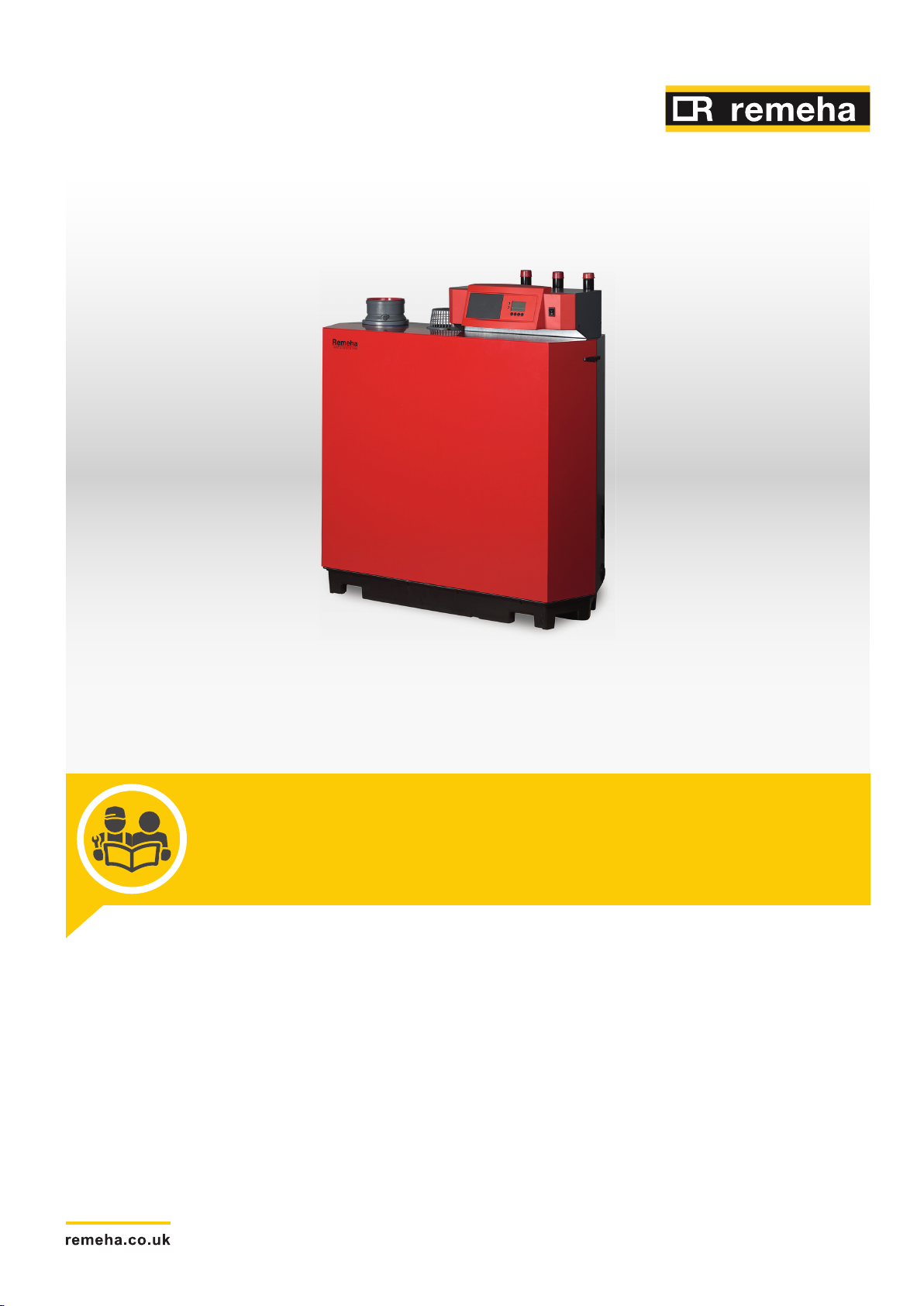
High-efficiency floor-standing gas boiler
Gas 210 ECO PRO
210-80 – 210-120 – 210-160 – 210-200

Dear Customer,
Thank you very much for buying this appliance.
Please read through the manual carefully before using the product, and keep it in a safe place for later reference. In order to
ensure continued safe and efficient operation we recommend that the product is serviced regularly. Our service and customer
service organisation can assist with this.
We hope you enjoy years of problem-free operation with the product.

Contents
114494 - v.05 - 06022018 3
Contents
1 Safety . . . . . . . . . . . . . . . . . . . . . . . . . . . . . . . . . . . . . . . . . . . . . . . . . . . . . . . . . . . . . . . . . . . . . . . . . . . . . . . . . . . . . . . . . . . . 6
1.1 General safety instructions . . . . . . . . . . . . . . . . . . . . . . . . . . . . . . . . . . . . . . . . . . . . . . . . . . . . . . . . . . . . . . . . . . . . . . . 6
1.2 Recommendations . . . . . . . . . . . . . . . . . . . . . . . . . . . . . . . . . . . . . . . . . . . . . . . . . . . . . . . . . . . . . . . . . . . . . . . . . . . . . 8
1.3 Specific safety instructions . . . . . . . . . . . . . . . . . . . . . . . . . . . . . . . . . . . . . . . . . . . . . . . . . . . . . . . . . . . . . . . . . . . . . . 10
1.3.1 Additional guidelines . . . . . . . . . . . . . . . . . . . . . . . . . . . . . . . . . . . . . . . . . . . . . . . . . . . . . . . . . . . . . . . . . . . 10
1.4 Liabilities . . . . . . . . . . . . . . . . . . . . . . . . . . . . . . . . . . . . . . . . . . . . . . . . . . . . . . . . . . . . . . . . . . . . . . . . . . . . . . . . . . . . 10
1.4.1 Manufacturer's liability . . . . . . . . . . . . . . . . . . . . . . . . . . . . . . . . . . . . . . . . . . . . . . . . . . . . . . . . . . . . . . . . . . 10
1.4.2 Installer's liability . . . . . . . . . . . . . . . . . . . . . . . . . . . . . . . . . . . . . . . . . . . . . . . . . . . . . . . . . . . . . . . . . . . . . . 10
1.4.3 User's liability . . . . . . . . . . . . . . . . . . . . . . . . . . . . . . . . . . . . . . . . . . . . . . . . . . . . . . . . . . . . . . . . . . . . . . . . .11
2 About this manual . . . . . . . . . . . . . . . . . . . . . . . . . . . . . . . . . . . . . . . . . . . . . . . . . . . . . . . . . . . . . . . . . . . . . . . . . . . . . . . . . . 12
2.1 General . . . . . . . . . . . . . . . . . . . . . . . . . . . . . . . . . . . . . . . . . . . . . . . . . . . . . . . . . . . . . . . . . . . . . . . . . . . . . . . . . . . . . 12
2.2 Additional documentation . . . . . . . . . . . . . . . . . . . . . . . . . . . . . . . . . . . . . . . . . . . . . . . . . . . . . . . . . . . . . . . . . . . . . . . 12
2.3 Symbols used in the manual . . . . . . . . . . . . . . . . . . . . . . . . . . . . . . . . . . . . . . . . . . . . . . . . . . . . . . . . . . . . . . . . . . . . .12
3 Technical specifications . . . . . . . . . . . . . . . . . . . . . . . . . . . . . . . . . . . . . . . . . . . . . . . . . . . . . . . . . . . . . . . . . . . . . . . . . . . . . 13
3.1 Homologations . . . . . . . . . . . . . . . . . . . . . . . . . . . . . . . . . . . . . . . . . . . . . . . . . . . . . . . . . . . . . . . . . . . . . . . . . . . . . . . 13
3.1.1 Certifications . . . . . . . . . . . . . . . . . . . . . . . . . . . . . . . . . . . . . . . . . . . . . . . . . . . . . . . . . . . . . . . . . . . . . . . . . 13
3.1.2 Unit categories . . . . . . . . . . . . . . . . . . . . . . . . . . . . . . . . . . . . . . . . . . . . . . . . . . . . . . . . . . . . . . . . . . . . . . . .13
3.1.3 Directives . . . . . . . . . . . . . . . . . . . . . . . . . . . . . . . . . . . . . . . . . . . . . . . . . . . . . . . . . . . . . . . . . . . . . . . . . . . .13
3.1.4 Factory test . . . . . . . . . . . . . . . . . . . . . . . . . . . . . . . . . . . . . . . . . . . . . . . . . . . . . . . . . . . . . . . . . . . . . . . . . . 13
3.2 Technical data . . . . . . . . . . . . . . . . . . . . . . . . . . . . . . . . . . . . . . . . . . . . . . . . . . . . . . . . . . . . . . . . . . . . . . . . . . . . . . . .13
3.3 Dimensions and connections . . . . . . . . . . . . . . . . . . . . . . . . . . . . . . . . . . . . . . . . . . . . . . . . . . . . . . . . . . . . . . . . . . . . 16
3.4 Electrical diagram . . . . . . . . . . . . . . . . . . . . . . . . . . . . . . . . . . . . . . . . . . . . . . . . . . . . . . . . . . . . . . . . . . . . . . . . . . . . . 17
4 Description of the product . . . . . . . . . . . . . . . . . . . . . . . . . . . . . . . . . . . . . . . . . . . . . . . . . . . . . . . . . . . . . . . . . . . . . . . . . . . . 19
4.1 General description . . . . . . . . . . . . . . . . . . . . . . . . . . . . . . . . . . . . . . . . . . . . . . . . . . . . . . . . . . . . . . . . . . . . . . . . . . . .19
4.2 Operating principle . . . . . . . . . . . . . . . . . . . . . . . . . . . . . . . . . . . . . . . . . . . . . . . . . . . . . . . . . . . . . . . . . . . . . . . . . . . . 19
4.2.1 Gas/air regulation . . . . . . . . . . . . . . . . . . . . . . . . . . . . . . . . . . . . . . . . . . . . . . . . . . . . . . . . . . . . . . . . . . . . . 19
4.2.2 Control . . . . . . . . . . . . . . . . . . . . . . . . . . . . . . . . . . . . . . . . . . . . . . . . . . . . . . . . . . . . . . . . . . . . . . . . . . . . . . 19
4.2.3 Circulation pump . . . . . . . . . . . . . . . . . . . . . . . . . . . . . . . . . . . . . . . . . . . . . . . . . . . . . . . . . . . . . . . . . . . . . . 19
4.3 Gas 210 ECO PRO main components . . . . . . . . . . . . . . . . . . . . . . . . . . . . . . . . . . . . . . . . . . . . . . . . . . . . . . . . . . . . . 20
4.4 Control panel description . . . . . . . . . . . . . . . . . . . . . . . . . . . . . . . . . . . . . . . . . . . . . . . . . . . . . . . . . . . . . . . . . . . . . . . 20
4.5 Accessories and options . . . . . . . . . . . . . . . . . . . . . . . . . . . . . . . . . . . . . . . . . . . . . . . . . . . . . . . . . . . . . . . . . . . . . . . . 21
5 Before installation . . . . . . . . . . . . . . . . . . . . . . . . . . . . . . . . . . . . . . . . . . . . . . . . . . . . . . . . . . . . . . . . . . . . . . . . . . . . . . . . . . 22
5.1 Installation regulations . . . . . . . . . . . . . . . . . . . . . . . . . . . . . . . . . . . . . . . . . . . . . . . . . . . . . . . . . . . . . . . . . . . . . . . . . 22
5.2 Choice of the location . . . . . . . . . . . . . . . . . . . . . . . . . . . . . . . . . . . . . . . . . . . . . . . . . . . . . . . . . . . . . . . . . . . . . . . . . . 22
5.2.1 Data plate . . . . . . . . . . . . . . . . . . . . . . . . . . . . . . . . . . . . . . . . . . . . . . . . . . . . . . . . . . . . . . . . . . . . . . . . . . . 22
5.2.2 Location of the boiler . . . . . . . . . . . . . . . . . . . . . . . . . . . . . . . . . . . . . . . . . . . . . . . . . . . . . . . . . . . . . . . . . . . 23
5.3 Transport . . . . . . . . . . . . . . . . . . . . . . . . . . . . . . . . . . . . . . . . . . . . . . . . . . . . . . . . . . . . . . . . . . . . . . . . . . . . . . . . . . . .24
5.4 Unpacking & initial preparation . . . . . . . . . . . . . . . . . . . . . . . . . . . . . . . . . . . . . . . . . . . . . . . . . . . . . . . . . . . . . . . . . . . 24
6 Installation . . . . . . . . . . . . . . . . . . . . . . . . . . . . . . . . . . . . . . . . . . . . . . . . . . . . . . . . . . . . . . . . . . . . . . . . . . . . . . . . . . . . . . . . 25
6.1 General . . . . . . . . . . . . . . . . . . . . . . . . . . . . . . . . . . . . . . . . . . . . . . . . . . . . . . . . . . . . . . . . . . . . . . . . . . . . . . . . . . . . . 25
6.2 Hydraulic connections . . . . . . . . . . . . . . . . . . . . . . . . . . . . . . . . . . . . . . . . . . . . . . . . . . . . . . . . . . . . . . . . . . . . . . . . . .25
6.2.1 Rinsing the system . . . . . . . . . . . . . . . . . . . . . . . . . . . . . . . . . . . . . . . . . . . . . . . . . . . . . . . . . . . . . . . . . . . . 25
6.2.2 Connecting the heating circuit . . . . . . . . . . . . . . . . . . . . . . . . . . . . . . . . . . . . . . . . . . . . . . . . . . . . . . . . . . . . 25
6.2.3 Connecting the condensate discharge pipe . . . . . . . . . . . . . . . . . . . . . . . . . . . . . . . . . . . . . . . . . . . . . . . . . .26
6.3 Gas connection . . . . . . . . . . . . . . . . . . . . . . . . . . . . . . . . . . . . . . . . . . . . . . . . . . . . . . . . . . . . . . . . . . . . . . . . . . . . . . . 26
6.4 Air supply/flue gas connections . . . . . . . . . . . . . . . . . . . . . . . . . . . . . . . . . . . . . . . . . . . . . . . . . . . . . . . . . . . . . . . . . . 27
6.4.1 Classification . . . . . . . . . . . . . . . . . . . . . . . . . . . . . . . . . . . . . . . . . . . . . . . . . . . . . . . . . . . . . . . . . . . . . . . . . 27
6.4.2 Requirements for shaft for C93 . . . . . . . . . . . . . . . . . . . . . . . . . . . . . . . . . . . . . . . . . . . . . . . . . . . . . . . . . . . .28
6.4.3 Material . . . . . . . . . . . . . . . . . . . . . . . . . . . . . . . . . . . . . . . . . . . . . . . . . . . . . . . . . . . . . . . . . . . . . . . . . . . . . 29
6.4.4 Dimensions of flue gas outlet pipe . . . . . . . . . . . . . . . . . . . . . . . . . . . . . . . . . . . . . . . . . . . . . . . . . . . . . . . . .30
6.4.5 Length of the air and flue gas pipes . . . . . . . . . . . . . . . . . . . . . . . . . . . . . . . . . . . . . . . . . . . . . . . . . . . . . . . .30
6.4.6 Additional guidelines . . . . . . . . . . . . . . . . . . . . . . . . . . . . . . . . . . . . . . . . . . . . . . . . . . . . . . . . . . . . . . . . . . . 33
6.4.7 Air/flue gas adapter . . . . . . . . . . . . . . . . . . . . . . . . . . . . . . . . . . . . . . . . . . . . . . . . . . . . . . . . . . . . . . . . . . . . 33
6.4.8 Connecting the flue gas outlet . . . . . . . . . . . . . . . . . . . . . . . . . . . . . . . . . . . . . . . . . . . . . . . . . . . . . . . . . . . . 33
6.4.9 Connecting the air supply . . . . . . . . . . . . . . . . . . . . . . . . . . . . . . . . . . . . . . . . . . . . . . . . . . . . . . . . . . . . . . . 34
6.5 Electrical connections . . . . . . . . . . . . . . . . . . . . . . . . . . . . . . . . . . . . . . . . . . . . . . . . . . . . . . . . . . . . . . . . . . . . . . . . . . 34
6.5.1 Recommendations . . . . . . . . . . . . . . . . . . . . . . . . . . . . . . . . . . . . . . . . . . . . . . . . . . . . . . . . . . . . . . . . . . . . .34
6.5.2 Control unit . . . . . . . . . . . . . . . . . . . . . . . . . . . . . . . . . . . . . . . . . . . . . . . . . . . . . . . . . . . . . . . . . . . . . . . . . . 34
6.5.3 Accessing the terminal connectors and control PCBs . . . . . . . . . . . . . . . . . . . . . . . . . . . . . . . . . . . . . . . . . . 35

Contents
4 114494 - v.05 - 06022018
6.5.4 Connection options for the standard control PCB (PCU-01) . . . . . . . . . . . . . . . . . . . . . . . . . . . . . . . . . . . . . 36
6.5.5 Connection options for the 0–10 V PCB (IF-01) . . . . . . . . . . . . . . . . . . . . . . . . . . . . . . . . . . . . . . . . . . . . . . 37
6.5.6 Connection options for the PCB (SCU-X01) . . . . . . . . . . . . . . . . . . . . . . . . . . . . . . . . . . . . . . . . . . . . . . . . . 39
6.6 Filling the installation . . . . . . . . . . . . . . . . . . . . . . . . . . . . . . . . . . . . . . . . . . . . . . . . . . . . . . . . . . . . . . . . . . . . . . . . . . .39
6.6.1 Water treatment and water quality . . . . . . . . . . . . . . . . . . . . . . . . . . . . . . . . . . . . . . . . . . . . . . . . . . . . . . . . .39
6.6.2 Filling the siphon . . . . . . . . . . . . . . . . . . . . . . . . . . . . . . . . . . . . . . . . . . . . . . . . . . . . . . . . . . . . . . . . . . . . . . 40
6.6.3 Filling the installation . . . . . . . . . . . . . . . . . . . . . . . . . . . . . . . . . . . . . . . . . . . . . . . . . . . . . . . . . . . . . . . . . . . 40
7 Commissioning . . . . . . . . . . . . . . . . . . . . . . . . . . . . . . . . . . . . . . . . . . . . . . . . . . . . . . . . . . . . . . . . . . . . . . . . . . . . . . . . . . . . 41
7.1 Checklist before commissioning . . . . . . . . . . . . . . . . . . . . . . . . . . . . . . . . . . . . . . . . . . . . . . . . . . . . . . . . . . . . . . . . . . 41
7.1.1 Preparing the boiler for commissioning . . . . . . . . . . . . . . . . . . . . . . . . . . . . . . . . . . . . . . . . . . . . . . . . . . . . . 41
7.1.2 Gas circuit . . . . . . . . . . . . . . . . . . . . . . . . . . . . . . . . . . . . . . . . . . . . . . . . . . . . . . . . . . . . . . . . . . . . . . . . . . . 41
7.1.3 Hydraulic circuit . . . . . . . . . . . . . . . . . . . . . . . . . . . . . . . . . . . . . . . . . . . . . . . . . . . . . . . . . . . . . . . . . . . . . . . 41
7.1.4 Connections for the air and flue gas pipes . . . . . . . . . . . . . . . . . . . . . . . . . . . . . . . . . . . . . . . . . . . . . . . . . . 41
7.1.5 Electrical connections . . . . . . . . . . . . . . . . . . . . . . . . . . . . . . . . . . . . . . . . . . . . . . . . . . . . . . . . . . . . . . . . . . 41
7.2 Commissioning procedure . . . . . . . . . . . . . . . . . . . . . . . . . . . . . . . . . . . . . . . . . . . . . . . . . . . . . . . . . . . . . . . . . . . . . . 41
7.3 Gas settings . . . . . . . . . . . . . . . . . . . . . . . . . . . . . . . . . . . . . . . . . . . . . . . . . . . . . . . . . . . . . . . . . . . . . . . . . . . . . . . . . 42
7.3.1 Adaptation to a different gas type . . . . . . . . . . . . . . . . . . . . . . . . . . . . . . . . . . . . . . . . . . . . . . . . . . . . . . . . . 42
7.3.2 Checking/setting the combustion . . . . . . . . . . . . . . . . . . . . . . . . . . . . . . . . . . . . . . . . . . . . . . . . . . . . . . . . . .42
7.4 Final instructions . . . . . . . . . . . . . . . . . . . . . . . . . . . . . . . . . . . . . . . . . . . . . . . . . . . . . . . . . . . . . . . . . . . . . . . . . . . . . . 45
8 Operation . . . . . . . . . . . . . . . . . . . . . . . . . . . . . . . . . . . . . . . . . . . . . . . . . . . . . . . . . . . . . . . . . . . . . . . . . . . . . . . . . . . . . . . . .46
8.1 Use of the control panel . . . . . . . . . . . . . . . . . . . . . . . . . . . . . . . . . . . . . . . . . . . . . . . . . . . . . . . . . . . . . . . . . . . . . . . . 46
8.2 Shutdown . . . . . . . . . . . . . . . . . . . . . . . . . . . . . . . . . . . . . . . . . . . . . . . . . . . . . . . . . . . . . . . . . . . . . . . . . . . . . . . . . . . 46
8.3 Frost protection . . . . . . . . . . . . . . . . . . . . . . . . . . . . . . . . . . . . . . . . . . . . . . . . . . . . . . . . . . . . . . . . . . . . . . . . . . . . . . . 46
9 Settings . . . . . . . . . . . . . . . . . . . . . . . . . . . . . . . . . . . . . . . . . . . . . . . . . . . . . . . . . . . . . . . . . . . . . . . . . . . . . . . . . . . . . . . . . . 47
9.1 Description of Gas 210 ECO PRO parameters . . . . . . . . . . . . . . . . . . . . . . . . . . . . . . . . . . . . . . . . . . . . . . . . . . . . . . .47
9.2 Changing the parameters . . . . . . . . . . . . . . . . . . . . . . . . . . . . . . . . . . . . . . . . . . . . . . . . . . . . . . . . . . . . . . . . . . . . . . . 48
9.2.1 Setting the parameters in the Installer level . . . . . . . . . . . . . . . . . . . . . . . . . . . . . . . . . . . . . . . . . . . . . . . . . .49
9.3 Reading out measured values . . . . . . . . . . . . . . . . . . . . . . . . . . . . . . . . . . . . . . . . . . . . . . . . . . . . . . . . . . . . . . . . . . . 49
9.3.1 Reading current values . . . . . . . . . . . . . . . . . . . . . . . . . . . . . . . . . . . . . . . . . . . . . . . . . . . . . . . . . . . . . . . . . 49
9.3.2 Status and sub-status . . . . . . . . . . . . . . . . . . . . . . . . . . . . . . . . . . . . . . . . . . . . . . . . . . . . . . . . . . . . . . . . . . 50
10 Maintenance . . . . . . . . . . . . . . . . . . . . . . . . . . . . . . . . . . . . . . . . . . . . . . . . . . . . . . . . . . . . . . . . . . . . . . . . . . . . . . . . . . . . . . 52
10.1 General . . . . . . . . . . . . . . . . . . . . . . . . . . . . . . . . . . . . . . . . . . . . . . . . . . . . . . . . . . . . . . . . . . . . . . . . . . . . . . . . . . . . . 52
10.2 Standard inspection and maintenance operations . . . . . . . . . . . . . . . . . . . . . . . . . . . . . . . . . . . . . . . . . . . . . . . . . . . . 52
10.2.1 Checking the water pressure . . . . . . . . . . . . . . . . . . . . . . . . . . . . . . . . . . . . . . . . . . . . . . . . . . . . . . . . . . . . . 52
10.2.2 Checking the water quality . . . . . . . . . . . . . . . . . . . . . . . . . . . . . . . . . . . . . . . . . . . . . . . . . . . . . . . . . . . . . . .52
10.2.3 Checking the ionisation current . . . . . . . . . . . . . . . . . . . . . . . . . . . . . . . . . . . . . . . . . . . . . . . . . . . . . . . . . . . 52
10.2.4 Check the flue gas outlet/air supply connections . . . . . . . . . . . . . . . . . . . . . . . . . . . . . . . . . . . . . . . . . . . . . .52
10.2.5 Checking the combustion . . . . . . . . . . . . . . . . . . . . . . . . . . . . . . . . . . . . . . . . . . . . . . . . . . . . . . . . . . . . . . . 53
10.2.6 Cleaning the siphon . . . . . . . . . . . . . . . . . . . . . . . . . . . . . . . . . . . . . . . . . . . . . . . . . . . . . . . . . . . . . . . . . . . . 53
10.3 Specific maintenance work . . . . . . . . . . . . . . . . . . . . . . . . . . . . . . . . . . . . . . . . . . . . . . . . . . . . . . . . . . . . . . . . . . . . . . 53
10.3.1 Cleaning the fan . . . . . . . . . . . . . . . . . . . . . . . . . . . . . . . . . . . . . . . . . . . . . . . . . . . . . . . . . . . . . . . . . . . . . . .54
10.3.2 Clean heat exchanger . . . . . . . . . . . . . . . . . . . . . . . . . . . . . . . . . . . . . . . . . . . . . . . . . . . . . . . . . . . . . . . . . . 56
10.3.3 Cleaning the burner . . . . . . . . . . . . . . . . . . . . . . . . . . . . . . . . . . . . . . . . . . . . . . . . . . . . . . . . . . . . . . . . . . . . 57
10.3.4 Replacing the ionisation/ignition electrode . . . . . . . . . . . . . . . . . . . . . . . . . . . . . . . . . . . . . . . . . . . . . . . . . . 57
10.3.5 Reassembling the boiler . . . . . . . . . . . . . . . . . . . . . . . . . . . . . . . . . . . . . . . . . . . . . . . . . . . . . . . . . . . . . . . . 58
11 Troubleshooting . . . . . . . . . . . . . . . . . . . . . . . . . . . . . . . . . . . . . . . . . . . . . . . . . . . . . . . . . . . . . . . . . . . . . . . . . . . . . . . . . . . .59
11.1 Error codes . . . . . . . . . . . . . . . . . . . . . . . . . . . . . . . . . . . . . . . . . . . . . . . . . . . . . . . . . . . . . . . . . . . . . . . . . . . . . . . . . . 59
11.1.1 Blocking . . . . . . . . . . . . . . . . . . . . . . . . . . . . . . . . . . . . . . . . . . . . . . . . . . . . . . . . . . . . . . . . . . . . . . . . . . . . . 59
11.1.2 Lock out . . . . . . . . . . . . . . . . . . . . . . . . . . . . . . . . . . . . . . . . . . . . . . . . . . . . . . . . . . . . . . . . . . . . . . . . . . . . . 61
11.2 Blockage and fault memory . . . . . . . . . . . . . . . . . . . . . . . . . . . . . . . . . . . . . . . . . . . . . . . . . . . . . . . . . . . . . . . . . . . . . .65
12 Disposal . . . . . . . . . . . . . . . . . . . . . . . . . . . . . . . . . . . . . . . . . . . . . . . . . . . . . . . . . . . . . . . . . . . . . . . . . . . . . . . . . . . . . . . . . .66
12.1 Removal/recycling . . . . . . . . . . . . . . . . . . . . . . . . . . . . . . . . . . . . . . . . . . . . . . . . . . . . . . . . . . . . . . . . . . . . . . . . . . . . .66
13 Spare parts . . . . . . . . . . . . . . . . . . . . . . . . . . . . . . . . . . . . . . . . . . . . . . . . . . . . . . . . . . . . . . . . . . . . . . . . . . . . . . . . . . . . . . . 67
13.1 General . . . . . . . . . . . . . . . . . . . . . . . . . . . . . . . . . . . . . . . . . . . . . . . . . . . . . . . . . . . . . . . . . . . . . . . . . . . . . . . . . . . . . 67
13.2 Parts . . . . . . . . . . . . . . . . . . . . . . . . . . . . . . . . . . . . . . . . . . . . . . . . . . . . . . . . . . . . . . . . . . . . . . . . . . . . . . . . . . . . . . . 68
14 Appendix . . . . . . . . . . . . . . . . . . . . . . . . . . . . . . . . . . . . . . . . . . . . . . . . . . . . . . . . . . . . . . . . . . . . . . . . . . . . . . . . . . . . . . . . . 69
14.1 ErP information . . . . . . . . . . . . . . . . . . . . . . . . . . . . . . . . . . . . . . . . . . . . . . . . . . . . . . . . . . . . . . . . . . . . . . . . . . . . . . . 69
14.1.1 Product card . . . . . . . . . . . . . . . . . . . . . . . . . . . . . . . . . . . . . . . . . . . . . . . . . . . . . . . . . . . . . . . . . . . . . . . . . 69

Contents
114494 - v.05 - 06022018 5
14.2 Optional electrical connections . . . . . . . . . . . . . . . . . . . . . . . . . . . . . . . . . . . . . . . . . . . . . . . . . . . . . . . . . . . . . . . . . . . 69
14.2.1 Connection options for the control PCB (SCU-S01) . . . . . . . . . . . . . . . . . . . . . . . . . . . . . . . . . . . . . . . . . . . 69
14.2.2 Connection options for the PCB (SCU-X03) . . . . . . . . . . . . . . . . . . . . . . . . . . . . . . . . . . . . . . . . . . . . . . . . . 69
1 Safety
6 114494 - v.05 - 06022018
1 Safety
1.1 General safety instructions
For the installer:
Danger
If you smell gas:
1. Do not use naked flames, do not smoke and
do not operate electrical contacts or switches
(doorbell, lighting, motor, lift etc).
2. Shut off the gas supply.
3. Open the windows.
4. Trace possible leaks and seal them off imme
diately.
5. If the leak is upstream of the gas meter, notify
the gas company.
Danger
If you smell flue gases:
1. Switch the boiler off.
2. Open the windows.
3. Trace possible leaks and seal them off imme
diately.
Caution
After maintenance or repair work, check the en
tire heating installation to ensure that there are no
leaks.
For the end user:
1 Safety
114494 - v.05 - 06022018 7
Danger
If you smell gas:
1. Do not use naked flames, do not smoke and
do not operate electrical contacts or switches
(doorbell, lighting, motor, lift etc).
2. Shut off the gas supply.
3. Open the windows.
4. Report any leaks immediately.
5. Evacuate the property.
6. Contact a qualified installer.
Danger
If you smell flue gases:
1. Switch the boiler off.
2. Open the windows.
3. Report any leaks immediately.
4. Evacuate the property.
5. Contact a qualified installer.
Warning
Do not touch the flue gas pipes. Depending on
the boiler settings, the temperature of the flue gas
pipes can rise to over 60°C.
Warning
Do not touch radiators for long periods. Depend
ing on the boiler settings, the temperature of the
radiators can rise to over 60°C.
Warning
Be careful when using the domestic hot water.
Depending on the boiler settings, the temperature
of domestic hot water can rise to over 65°C.
Warning
The use of the boiler and the installation by you
as the end-user must be limited to the operations
described in this manual. All other actions may
only be undertaken by a qualified fitter/engineer.
Warning
The condensation drain must not be changed or
sealed. If a condensate neutralisation system is
used, the system must be cleaned regularly in ac
cordance with the instructions provided by the
manufacturer.
1 Safety
8 114494 - v.05 - 06022018
Caution
Ensure that the boiler is regularly serviced. Con
tact a qualified installer or arrange a maintenance
contract for the servicing of the boiler.
Caution
Only genuine spare parts may be used.
Important
Regularly check for the presence of water and
pressure in the heating installation.
1.2
Recommendations
Danger
This appliance can be used by children aged
eight and above and people with a physical, sen
sory or mental disability, or with a lack of experi
ence and knowledge, provided they are super
vised and instructed in how to use the appliance
in a safe manner and understand the associated
dangers. Children must not be allowed to play
with the appliance. Cleaning and user mainte
nance should not be carried out by children with
out adult supervision.
Warning
Installation and maintenance of the boiler must be
carried out by a qualified installer in accordance
with local and national regulations.
Warning
The installation and maintenance of the boiler
must be undertaken by a qualified installer in ac
cordance with the information in the supplied
manual, doing otherwise may result in dangerous
situations and/or bodily injury.
Warning
Removal and disposal of the boiler must be car
ried out by a qualified installer in accordance with
local and national regulations.
Warning
If the mains lead is damaged, it must be replaced
by the original manufacturer, the manufacturer's
dealer or another suitably skilled person to pre
vent hazardous situations from arising.
1 Safety
114494 - v.05 - 06022018 9
Warning
Always disconnect the mains supply and close
the main gas tap when working on the boiler.
Warning
Check the entire system for leaks after mainte
nance and servicing work.
Danger
For safety reasons, we recommend fitting smoke
and CO alarms at suitable places in your home.
Caution
Make sure the boiler can be reached at all
times.
The boiler must be installed in a frost-free area.
If the power cord is permanently connected, you
must always install a main bipolar switch with
an opening gap of at least 3 mm (BS EN
60335-1).
Drain the boiler and central heating system if
you are not going to use your home for a long
time and there is a chance of frost.
The frost protection does not work if the boiler is
out of operation.
The boiler protection only protects the boiler,
not the system.
Check the water pressure in the system regular
ly. If the water pressure is lower than 0.8 bar,
the system must be topped up (recommended
water pressure between 1.5 and 2 bar).
Important
Keep this document near to the boiler.
Important
Only remove the casing for maintenance and re
pair operations. Refit all panels when mainte
nance work and servicing are complete.
Important
Instruction and warning labels must never be re
moved or covered and must be clearly legible
throughout the entire service life of the boiler.
Damaged or illegible instructions and warning
stickers must be replaced immediately.
Important
Modifications to the boiler require the written ap
proval of Remeha.

1 Safety
10 114494 - v.05 - 06022018
1.3 Specific safety instructions
1.3.1 Additional guidelines
In addition to the legal requirements and guidelines, the
supplementary guidelines in this manual must also be
followed. Supplements or subsequent regulations and
guidelines that are valid at the time of installation shall
apply to all regulations and guidelines specified in this
manual.
1.4 Liabilities
1.4.1
Our products are manufactured in compliance with the
requirements of the various Directives applicable. They
are therefore delivered with the
documents necessary. In the interests of the quality of
our products, we strive constantly to improve them. We
therefore reserve the right to modify the specifications
given in this document.
Our liability as manufacturer may not be invoked in the
following cases:
Failure to abide by the instructions on installing the
appliance.
Failure to abide by the instructions on using the appli
ance.
Faulty or insufficient maintenance of the appliance.
1.4.2
The installer is responsible for the installation and initial
commissioning of the appliance. The installer must ob
serve the following instructions:
Manufacturer's liability
marking and any
Installer's liability
Read and follow the instructions given in the manuals
provided with the appliance.
Install the appliance in compliance with prevailing leg
islation and standards.
Carry out initial commissioning and any checks neces
sary.
Explain the installation to the user.
If maintenance is necessary, warn the user of the obli
gation to check the appliance and keep it in good
working order.
Give all the instruction manuals to the user.

1 Safety
114494 - v.05 - 06022018 11
1.4.3
User's liability
To guarantee optimum operation of the system, you
must abide by the following instructions:
Read and follow the instructions given in the manuals
provided with the appliance.
Call on a qualified professional to carry out installation
and initial commissioning.
Get your installer to explain your installation to you.
Have the required inspections and maintenance car
ried out by a qualified installer.
Keep the instruction manuals in good condition close
to the appliance.
2 About this manual
12 114494 - v.05 - 06022018
2 About this manual
2.1 General
This manual describes the installation, use and maintenance of the Gas
210 ECO PRO boiler. This manual is part of all the documentation sup
plied with the boiler.
2.2
2.3
Additional documentation
The following documentation is available in addition to this manual:
Installation and user manual for control panel
Water quality instructions
Symbols used in the manual
This manual uses various danger levels to draw attention to special in
structions. We do this to improve user safety, to prevent problems and to
guarantee correct operation of the appliance.
Danger
Risk of dangerous situations that may result in serious personal
injury.
Danger of electric shock
Risk of electric shock.
Warning
Risk of dangerous situations that may result in minor personal in
jury.
Caution
Risk of material damage.
Important
Please note: important information.
See
Reference to other manuals or pages in this manual.
3 Technical specifications
114494 - v.05 - 06022018 13
3.1 Homologations
3.1.1 Certifications
Tab.1 Certifications
CE identification number PIN 0085BS0132
Class NOx
(1)
6
3 Technical specifications
Type of connection B
(1) EN 15502–1
23P
C13, C33, C53, C63, C
93
3.1.2 Unit categories
Tab.2 Unit categories
Country Category Gas type Connection pressure (mbar)
Great Britain II
2H3P
G20 (H gas)
G31 (propane)
20
37-50
3.1.3 Directives
In addition to the legal requirements and guidelines, the supplementary
guidelines in this manual must also be followed.
Supplements or subsequent regulations and guidelines that are valid at
the time of installation shall apply to all regulations and guidelines speci
fied in this manual.
3.1.4 Factory test
Before leaving the factory, each boiler is optimally set and tested for:
Electrical safety.
Adjustment of (O2/CO2).
Water tightness.
Gas tightness.
Parameter setting.
3.2
Technical data
Tab.3 General
Gas 210 ECO PRO 210-80 210-120 210-160 210-200
Nominal output (Pn)
Central heating operation (80/60°C)
Nominal output (Pn)
Central heating operation (50/30°C)
Nominal load (Qnh)
Central heating operation (Hi)
Nominal load (Qnh)
Central heating operation (Hs)
min-max
(1)
min-max
(1)
min-max
(1)
min-max
(1)
kW 16 - 87
87
kW 18 - 93
93
kW 17 - 89
89
kW 19 - 99
99
22 - 115
115.0
24 - 129
129
23 - 123
123
26 - 137
137
29 - 166
166
33 - 179
179
31 - 170
170
34 - 189
189
39 - 200
200
44 - 217
217
41 - 205
205
46 - 228
228
3 Technical specifications
14 114494 - v.05 - 06022018
Gas 210 ECO PRO 210-80 210-120 210-160 210-200
Full load central heating efficiency (Hi)
% 97.43 97.5 97.54 97.6
80°C/60°C
(92/42 EEC)
Full load central heating efficiency (Hi)
% 104.3 104.7 105.2 105.7
50/30°C
(EN15502)
Central heating efficiency under low load
% 92.7 94.0 95.1 95.5
(Hi)
(Return temperature 60 °C)
Part load central heating efficiency (92/42
% 108.6 108.1 108.3 108.4
EEC)
(Return temperature 30 °C)
(1) Factory setting
Tab.4 Gas and flue gas data
Gas 210 ECO PRO 210-80 210-120 210-160 210-200
Gas inlet pressure G20 (H gas) min-max mbar 17 - 25 17 - 25 17 - 25 17 - 25
Gas inlet pressure G25 (L gas) min-max mbar 20 - 30 20 - 30 20 - 30 20 - 30
Gas inlet pressure G31 (propane) min-max mbar 37 - 50 37 - 50 37 - 50 37 - 50
Gas consumption G20 (H gas) min-max
m3/h
1.8 - 9.4 2.4 - 13 3.3 - 18 4.3 - 21.7
Gas consumption G25 (L gas) min-max
Gas consumption G31 (propane) min-max
m3/h
m3/h
2.1 - 11 2.8 - 15.1 3.8 - 20.9 2.1 - 25.2
1.0 - 3.6 1.0 - 4.8 1.6 - 7.0 1.8 - 8.4
NOx annual emission (BREEAM) mg/kWh - - - -
Flue gas quantity min-max kg/h 27 - 150 37 - 197 39 - 287 65 - 345
Flue gas temperature min-max °C 30 - 63 30 - 64 30 - 62 30 - 64
Maximum counter pressure Pa 130 130 130 130
Tab.5 Central heating circuit data
Gas 210 ECO PRO 210-80 210-120 210-160 210-200
Water content l 12 16 20 24
Water operating pressure min bar 0.8 0.8 0.8 0.8
Water operating pressure (PMS) max bar 6.0 6.0 6.0 6.0
Water temperature max °C 110 110 110 110
Operating temperature max °C 90 90 90 90
Water resistance (ΔT=20K) mbar 165 135 170 180
Minimum flow l/h 1120 1486 2142 2585
Tab.6 Electrical data
Gas 210 ECO PRO 210-80 210-120 210-160 210-200
Supply voltage V~ 230 230 230 230
Power consumption – full load max W 125 193 206 317
Power consumption – low load min W 36 37 53 54
Power consumption – standby min W 4 4 4 4
Electrical protection index IP 20 20 20 20

3 Technical specifications
114494 - v.05 - 06022018 15
Gas 210 ECO PRO 210-80 210-120 210-160 210-200
Fuse – main fuse (A) 6.3 AT 6.3 AT 6.3 AT 6.3 AT
Fuse – PCB (A) 1.6 AT 1.6 AT 1.6 AT 1.6 AT
Tab.7 Other data
Gas 210 ECO PRO 210-80 210-120 210-160 210-200
Total weight (empty) kg 115 135 165 188
Average acoustic level
1 metre from the boiler
(1) Maximum
(1)
at a distance of
Central heating
operation
dB(A) ≤ 59 ≤ 59 ≤ 59 ≤ 59
Tab.8 Technical parameters
Gas 210 ECO PRO 210-80 210-120 210-160 210-200
Condensing boiler Yes Yes Yes Yes
Low-temperature boiler
(1)
Yes Yes Yes Yes
B1 boiler No No No No
Cogeneration space heater No No No No
Combination heater No No No No
Rated heat output
Useful heat output at nominal heat out
put and high temperature operation
Useful heat output at 30% of rated heat
output and low temperature regime
Seasonal space heating energy efficiency
Useful efficiency at rated heat output
and high temperature regime
(2)
Useful efficiency at 30% of rated heat
output and low temperature regime
Prated
P
(2)
(1)
(1)
4
P
1
ƞ
s
ƞ
4
ƞ
1
kW 87 115 166 200
kW 87 115 166 200
kW 29.1 38.3 55.2 66.6
% - - - -
% 87.7 87.8 87.8 87.8
% 97.7 97.5 97.3 97.6
Auxiliary electricity consumption
Full load
Part load
Standby mode
elmax
elmin
P
SB
kW 0.1 0.2 0.2 0.3
kW 0.0 0.0 0.1 0.1
kW 0.004 0.004 0.004 0.004
Other items
Standby heat loss
Ignition burner power consumption
Annual energy consumption
P
stby
P
ign
Q
HE
kW - - - -
kW - - - -
kWh
- - - -
GJ
Sound power level, indoors
Emissions of nitrogen oxides NO
(1) Low temperature means 30°C for condensing boilers, 37°C for low temperature boilers and 50°C (at heater inlet) for other heating appli
ances.
(2) High temperature operation means 60 °C return temperature at heater inlet and 80 °C feed temperature at heater outlet.
L
WA
X
dB 67 67 67 67
mg/kWh 56 49 44 52
See
Refer to the back cover for contact details.
AD-0001419-01
1200
A
1272
152
316
1070 125
450
1190
305160 140140 121
61
61
3 Technical specifications
16 114494 - v.05 - 06022018
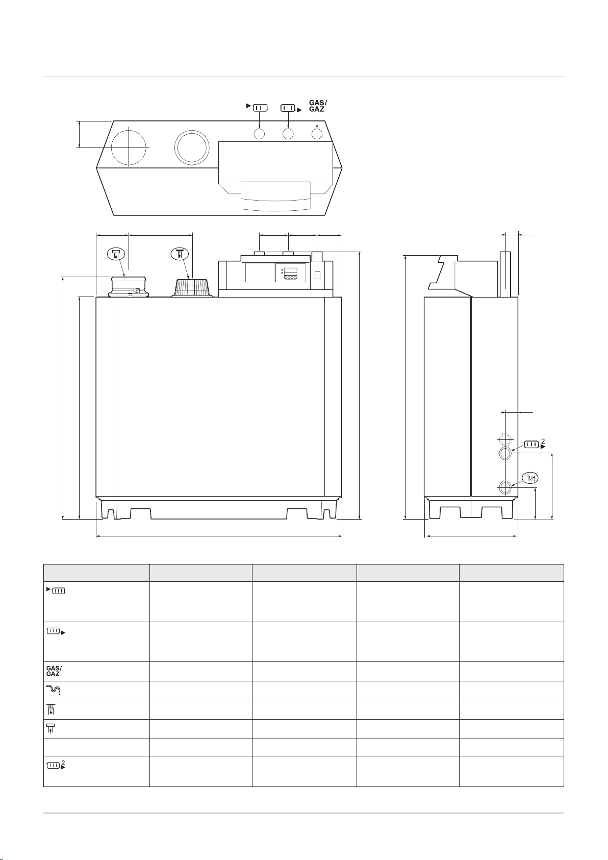
3.3 Dimensions and connections
Fig.1 Dimensions
Tab.9 Drawings
Connection 210-80 210-120 210-160 210-200
Supply
Return
Gas connection
Condensate drain
Combustion air supply
Flue gas outlet
1¼” male thread 1¼” male thread 1¼” male thread 1½” male thread
1¼” male thread 1¼” male thread 1¼” male thread 1½” male thread
1¼” male thread 1¼” male thread 1¼” male thread 1¼” male thread
Ø 32 mm external Ø 32 mm external Ø 32 mm external Ø 32 mm external
Ø150 mm Ø150 mm Ø150 mm Ø150 mm
Ø150 mm Ø150 mm Ø150 mm Ø150 mm
Height A 1309 mm 1309 mm 1309 mm 1324 mm
Second return (op
1¼” male thread 1¼” male thread 1¼” male thread 1¼” male thread
tional)
attach supplied 1¼” >
1½” adapter
attach supplied 1¼” >
1½” adapter
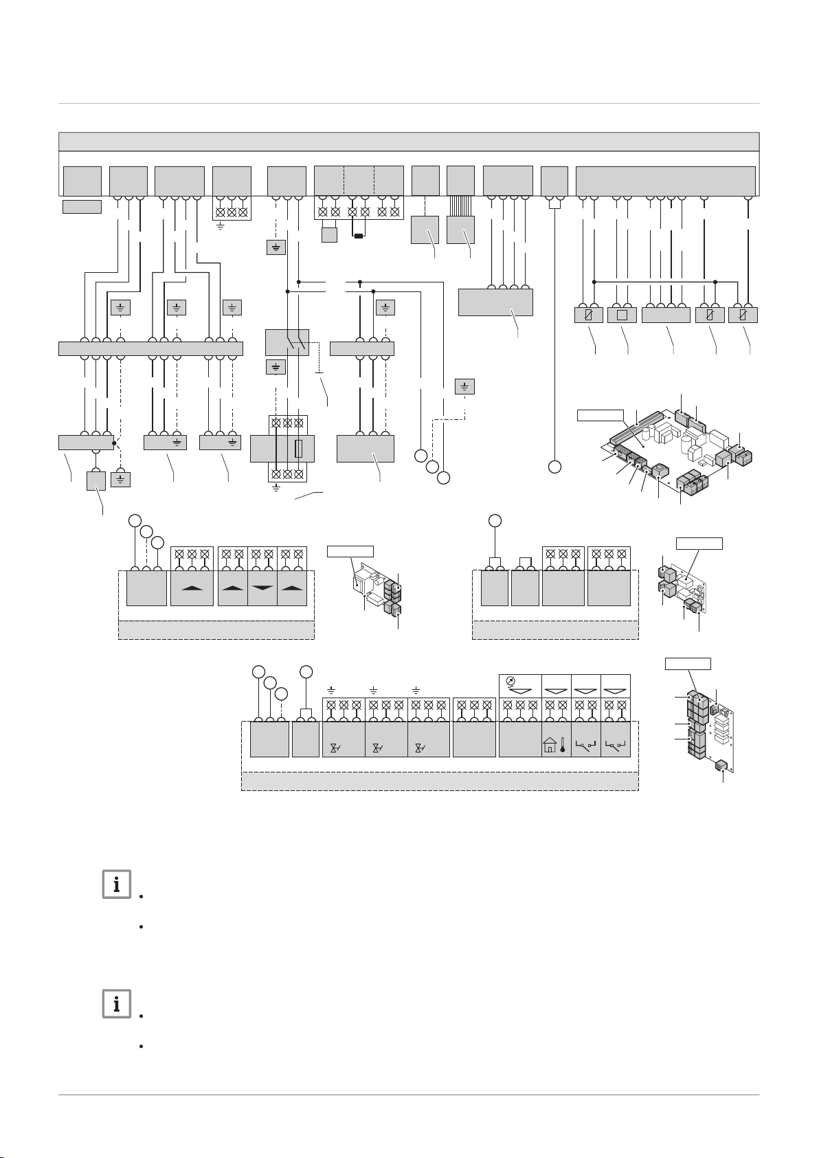
3.4 Electrical diagram
AD-3000122-01
X01
1 3
2
SCU-S01
X02
1.....6
Fgv
21
Hdv
4 5
Egv
7 83 6 9
N N NL L L
X03
Status
C NoNc
21 3
X04
O S +
21 4 5 6 73 8 9
X05
Wps Tout Gps VPs
D
A
C
B
X03
X04
X05
X02
X01
SCU-S01
X03
X04
X02a
X02
SCU-X01
SCU-X01
X02a
1.....6
X02
1.....6
Status
C NoNc
21 3
X03
Status
C NoNc
21 3
X04
D
X05
X04
X01
IF-01
IF-01
1 2
3
X01 X05
+
-
0-10V
+
-
0-10V
OTm
Nc
C
Status
No
X04
A
B
C
PCU-01
X02
X01
X03
X04
X11
X05
X10
X09
X08
X07
X06
PCU-01
X11
1 2 3 5 4 6 7 10 8 9
P
WH BK
RD BLOR
OR
YW/
WH
BR/
WH
BK/
WH
BL/
WH
X10
1.....6
D
X09
1 2 3 4
WH
BR
GN
YW
1X91 4 25
X08
1 10
X07
OT
1
On / Off
BL
3 4
RL
5 62
T
X06
BK
BL
PE-2
GN/YW
X50
6.3AT
LN
X51
X05
1 2 3
BL
BK
BL
BR
Mains
PE-2
PE-1
GN/YW
14X235 13 12
PE-7
GN/YW
1X55 32
BR
BL
GN/YW
P
230V,50Hz
BL
BK
GN/YW
A
B
C
X04
1 2
Pump
3
LN
X02
1 2 3
X03
1 2 3 4
213X21
E
BL
21 21
BR
BR
PE-6 PE-4 PE-5
PE-12
11X235 9 8 10 2 1 3 6 7 5
PE-11
GY
BL
BK
GN/YW
BL
BR
GN/YW
BL
BR
GN/YW
GN/YWGN/YWGN/YW
GY
BK
BL
BL
X01
SU-01
1
2
3 4
5
6
7 8
9
10 11 12 13 14
9
114494 - v.05 - 06022018 17
Fig.2 Electrical diagram
3 Technical specifications
1
Ignition transformer (IT)
2
Ionisation/ignition electrode (E)
3
Safety valve (SV1)
4
Important
Safety valve (SV2)
Important
For the 210-80 - 210-120, the gas valve unit
connection is 230 VAC.
For the 210-160 - 210-200, the gas valve
unit connection is 230 RAC.
For the 210-80 - 210-120 boilers, the gas
valve unit connection is 230 VAC.
For the 210-160 - 210-200 boilers, the gas
valve unit connection is 230 RAC.
5
Power supply (P)
6
On/off switch (S)
7
Computer connection (PC)
8
Control panel (HMI)
9
Fan (FAN)
10
Flow sensor (FTS)
11
Pressure switch (PS)
12
Storage parameter (PSU)
13
Return sensor (RTS)
14
Heat exchanger sensor (HTS)
BK
Black
BK/
Black/White
WH
BL
Blue
BL/
Blue/White
WH
BR
Brown

3 Technical specifications
18 114494 - v.05 - 06022018
BR/
WH
GN
GN/
YW
GY
Brown/White
Green
Green/Yellow
Grey
OR
RD
WH
YW
YW/
WH
Orange
Red
White
Yellow
Yellow/White

4 Description of the product
114494 - v.05 - 06022018 19
4.1 General description
4 Description of the product
The Gas 210 ECO PRO is a free-standing gas boiler with the following
characteristics:
High-efficiency heating.
Cast aluminium heat exchanger.
Limited emissions of polluted substances.
Has transport wheels as standard.
The following boiler types are available:
Gas 210 ECO PRO - 210-80
Gas 210 ECO PRO - 210-120
Gas 210 ECO PRO - 210-160
Gas 210 ECO PRO - 210-200
4.2
Operating principle
4.2.1
The boiler is equipped with a casing that also serves as an air box. The
fan draws in the combustion air. The gas is injected into the venturi and
mixed with the combustion air. The fan speed is controlled on the basis of
the settings, the heat demand and the prevailing temperatures measured
by the temperature sensors. The gas/air ratio control ensures an accurate
mixture of the required amounts of gas and air. This provides optimum
combustion over the entire heat input range. The gas/air mixture goes to
the burner, where it is ignited by the ignition electrode.
Gas/air regulation
4.2.2 Control
On/off control
The heat input varies between the minimum and the maximum values
on the basis of the flow temperature set on the boiler. It is possible to
connect a 2-wire on/off thermostat or a power stealing thermostat to the
boiler.
Modulating control
The heat input varies between the minimum and the maximum values
on the basis of the flow temperature determined by the modulating con
troller. The boiler output can be modulated with an appropriate modulat
ing controller.
Analogue control (0 - 10 V)
The heat input varies between the minimum and the maximum values
on the basis of the voltage present at the analogue input.
4.2.3 Circulation pump
The boiler does not have a built-in pump, but does have a built-in pump
switch. A circulating pump can be installed on the connector of the stand
ard control PCB. This can be an on/off pump or a modulating pump (with 0
- 10 V control).
The pump settings can be changed.
AD-4000038-02
1
2
3
4
5
6
7
8
9
10
11
12
13
14
15
16
17
18
19
20
21
22
23
24
25
26
28
27
2930
4 Description of the product
20 114494 - v.05 - 06022018
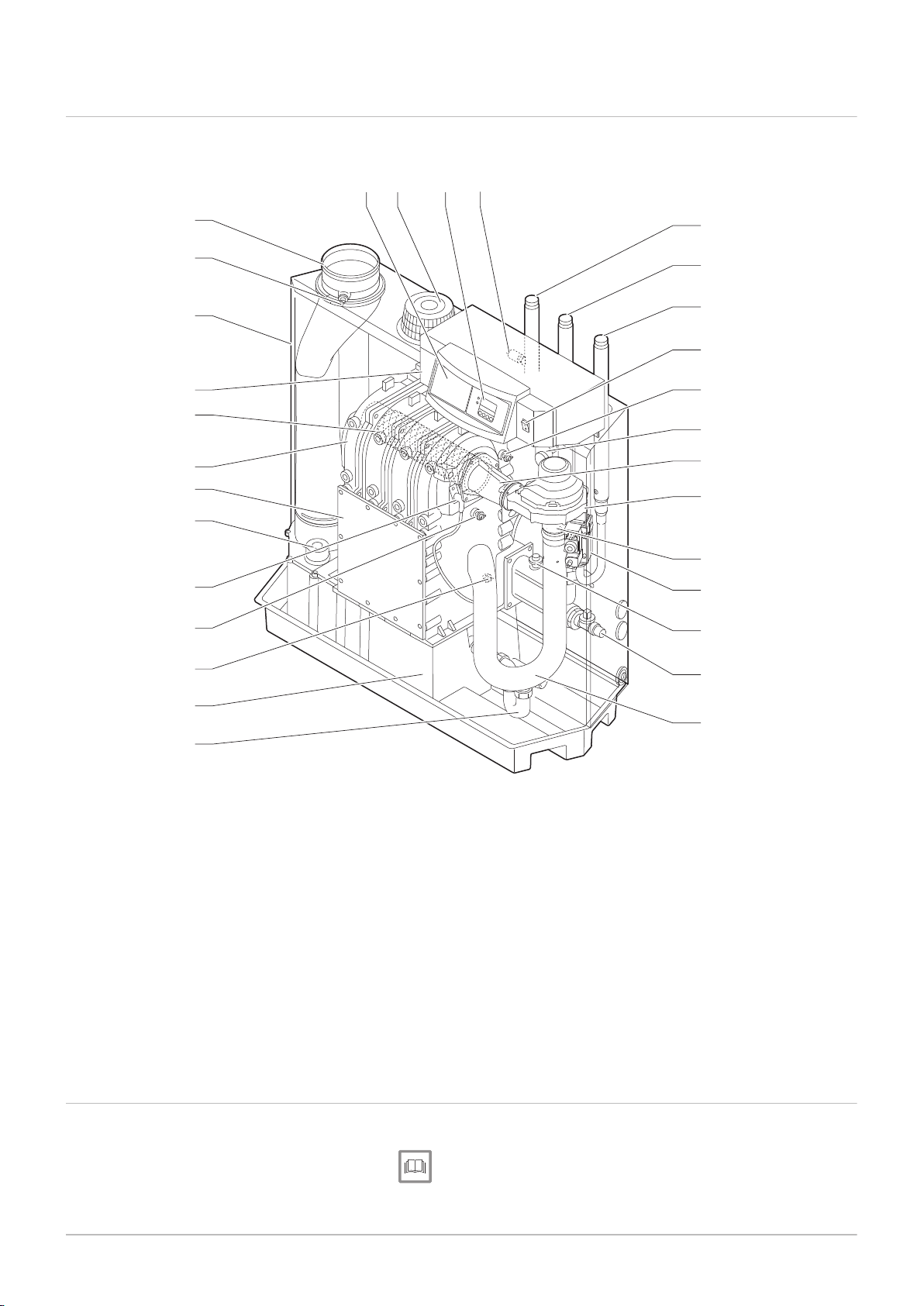
4.3 Gas 210 ECO PRO main components
Fig.3 Gas 210 ECO PRO
4.4
1
Flue gas outlet
2
O2/CO2 measurement point
3
Air box
4
Control panel
5
Burner
6
Heat exchanger
7
Inspection hatch
8
Inspection hatch for condensate collector box
9
Ignition pin
10
Boiler block sensor
11
Return temperature sensor
12
Condensate collector
13
Siphon
14
Intake silencer
15
Filling and drain valve
Control panel description
16
Hydraulic pressure sensor
17
Gas multi-block
18
Venturi
19
Fan
20
Mixing bend
21
Flue gas pressure switch
22
Flow temperature sensor
23
On/off switch
24
Gas connection
25
Return connection
26
Flow connection
27
Sensor pocket
28
display
29
Air nozzle
30
Optional built-in regulator
The Gas 210 ECO PRO boiler is supplied with a separate control panel.
See
Manual for the control panel.

4.5 Accessories and options
114494 - v.05 - 06022018 21
4 Description of the product
Various accessories can be obtained for the boiler.
Important
Contact us for more information.
AD-4000039-02
5 Before installation
22 114494 - v.05 - 06022018
5 Before installation
5.1 Installation regulations
Warning
The installer must be registered with Gas Safe and have the cor
rect ACS qualifications.
Important
Practical guidelines - see the latest version.
5.2
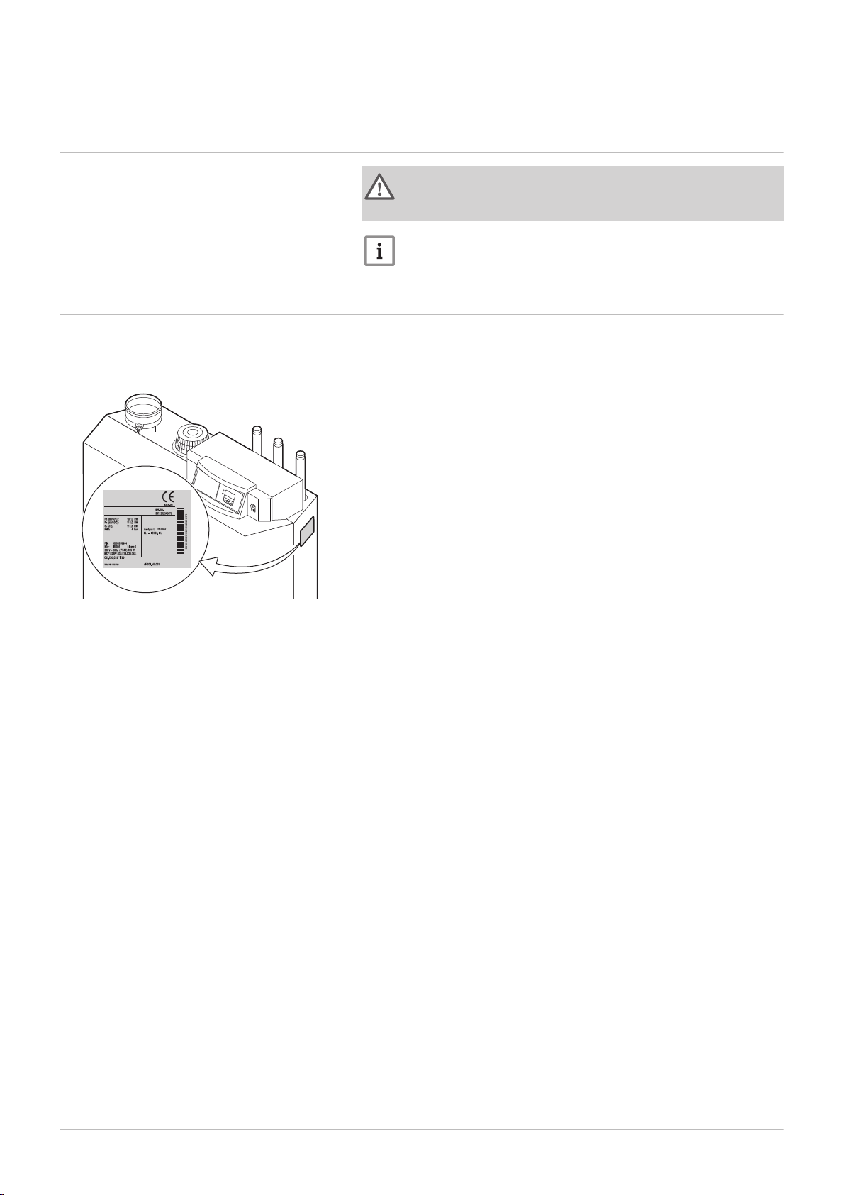
Fig.4
Choice of the location
Position of data plate
5.2.1 Data plate
The type plate is adhered above, against the casing on the right-hand
side.
 Loading...