

REMEHA Gas 210 ECO Technical Information
Technical information
Remeha Gas 210 ECO
• High efficiency condensing
Remeha Gas 210 ECO
boiler with low NOX emission
• Ranges: 8-214 kW
1

INHOUD
Remeha Gas 210 ECO
Preface 4
1 SAFETY instructions 5
1.1 Symbols 5
2 General boiler description 6
3 construction 7
3.1 Boiler layout 7
3.2 Operation principle 8
4 Technical data and dimensions 9
4.1 Dimensions 9
4.2 Technical data 10
4.3 Quotation specifications 11
4.4 Optional Accessories 11
5 Efficiency information 12
5.1 Annual efficiency 12
5.2 Heat to water efficiency 12
5.3 Standing losses 12
6 Application information 12
7 Control and safety equipment 12
7.1 The instrument panel 12
7.1.1 General 12
7.1.2 Layout of the instrument panel 12
7.1.3 Indication LED’s 13
7.1.4 Manual override (hand/auto or
forced modes ‘high’ and ‘low’) 13
7.1.5 Display of values with more than
two digits 14
7.2 Flow diagram control system 14
7.3 Operating mode (x [[) 15
7.4 Shut-off mode (b XX) 16
7.5 Setting mode user level (X [[) 17
7.5.1 Flow temperature setpoint (!) 17
7.5.2 Pump run on time (@) 18
7.5.3 Boiler control setting (A) 18
7.6 Setting mode service level (only for the
qualified service engineer) (X [[) 18
7.6.1 Low fire start point ($) 19
7.6.2 Boiler output to indicate high
fire (%) 20
7.6.3 Maximum output (6) 20
7.6.4 Forced part load and running
time (& en *) 20
7.6.5 Cycling prevention delay-time (() 20
7.6.6 Start and end point for analog
signal (a and B) 20
7.6.7 PWM pump position (C and D) 20
7.6.8 dT from control stop point to start
point (E) 20
7.6.9 Maximum flue gas tempe/
rature (F) 20
7.6.10 High limit temperature
setpoint (G) 20
7.6.11 Modulation start point dT (H) 20
7.6.12 Minimum water pressure (I) 21
7.6.13 Adjustments options/
accessories (J) 21
7.6.14 Base point internal compen/
sation slope (L) 21
7.6.15 Boiler type (P) 21
7.7 Read-out mode (X [[) 21
7.8 Failure mode(X [[) (service level) 22
7.9 Counter mode (1, , and .)
(service level) 22
7.9.1 Hours Run 23
7.9.2 Successful ignition attempts 23
7.9.3 Total start attempts 23
8 Installation instructions 24
8.1 General 24
8.2 Delivery, positioning and support surface 24
8.3 Flue gas discharge and air supply 25
8.3.1 General 25
8.3.2 Classification due to discharging
flue gases 26
8.3.3 Material and installation 26
8.3.4 Single boiler conventional flue 26
8.3.5 Single boiler, room sealed flue 27
8.3.6 Different pressure zones 27
8.3.7 Cascade flue systems 28
8.4 Installation details 28
8.4.1 Condensate discharge 28
8.4.2 Water treatment 28
8.4.3 Safety valve 29
8.4.4 Water circulation 29
8.5 Multiple installation 29
9 Electrical installation 31
9.1 General 31
9.2 Electrical specifications 31
9.2.1 Power supply 31
9.2.2 Automatic Controls 31
9.2.3 Fuse specification 31
9.2.4 Boiler temperature control 31
9.2.5 Low water protection
(flow and content) 31
9.2.6 High limit protection 31
9.2.7 Differential air pressure
switch (LD2) 31
9.3 Electrical connections 31
9.4 Boiler control 33
9.5 Safety interlocks 34
9.5.1 Shutdown interlock 34
9.5.2 Lockout interlock 34
9.6 Remaining outputs 34
9.6.1 Analog output 34
9.6.2 Indicating module No.1 35
2

9.7 Options/accessories 35
9.7.1 Provision for thermostat pocket 35
9.7.2 Water pressure sensor 35
9.7.3 Differential pressure sensor 35
9.7.4 Gas valve proving (only for
120, 160 and 200 kW boilers) 35
9.7.5 Minimum gas pressure switch 36
9.7.6 Indicating module No.2 36
9.8 Remaining connections 36
9.8.1 System pump 36
9.8.2 Frost protection 36
10 Commissioning 37
10.1 Initial lighting 37
10.2 Shutdown 39
11 Fault-finding 40
11.1 General 40
11.2 Overview malfunctions (locking) 40
12 Inspection and maintenance instructions 43
12.1 General 43
12.2 Combustion control 43
12.2.1 Corrective maintenance 43
12.2.2 Cleaning the IMS 43
12.2.3 Fan cleaning 43
12.2.4 Heat exchanger cleaning (exterior) 44
12.2.5 Burner cleaning 44
12.3 Lubrication Integrated Mixing System (IMS) 44
12.4 Siphon cleaning 44
12.5 Ignition probe control 44
12.6 Leakage control 44
12.7 Hydraulic pressure control 44
3
PREFACE
Remeha Gas 210 ECO
Read these instructions carefully before putting the
boiler into operation, familiarise yourself with its control
functions, operation and strictly observe the instructions
given. Failure to do so may invalidate warranty or prevent the boiler from operating.
The installation and commissioning of the boiler must be
carried out by a competent Engineer, with the relevant
certification i.e.: CORGI, ACOPS, IEE regs. On completion a copy of the commissioning sheet should be
returned to Broag Ltd. for record purposes.
If you have any questions, or if you need more information about specific subjects relating to this boiler or its
installation please do not hesitate to contact us.
The data published in these technical instructions is
based on the latest information (at date of publication)
and may be subject to revisions.
We reserve the right to continuous development in both
design and manufacture, therefore any changes to the
technology employed may not be retrospective nor may
we be obliged to adjust earlier supplies accordingly.
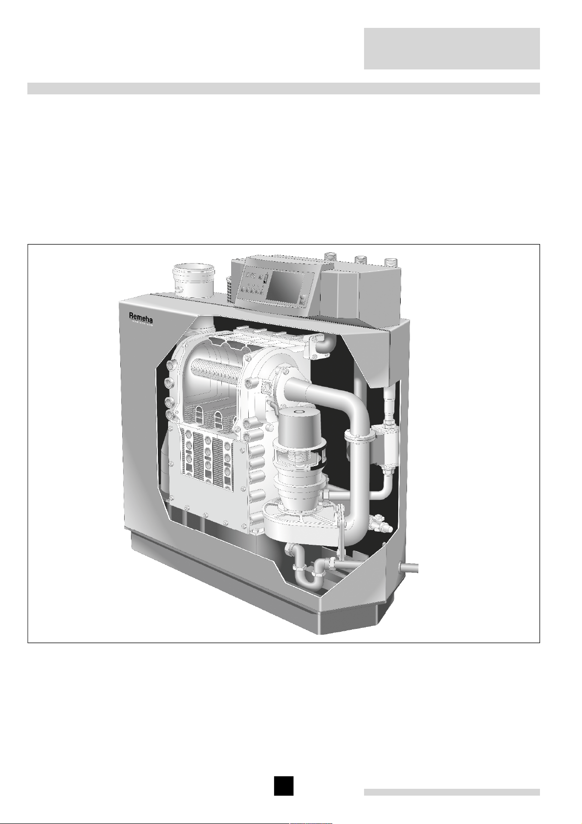
Fig. 01 Artist impression Gas 210 ECO
3D.AL.21H.000001
4

1 SAFETY INSTRUCTIONS
1.1 Symbols
The following symbols are used in this document to
emphasise certain instructions. This is in order to
increase your personal safety and to safeguard the technical reliability of the boiler.
g Instructions must be followed closely to avoid
personal injury or serious damage to the unit or the
environment.
g Important!! Instructions are of essential
importance for the correct functioning of the unit.
w Indicates possible danger of electric shock. Seri-
ous personal injury may occur.
i Instructions contain useful information.
Read and familiarise yourself with these instructions.
General Instructions
Keep unauthorised personnel away from the boiler. Do
not place objects on or against the boiler. Do not touch
hot water connections or the flue outlet when the boiler
is operating – burn hazard.
Casing panels should only be removed for maintenance and servicing purposes.
Refit all panels on completion of maintenance or servicing before putting the boiler back into service.
Instruction and warning labels on the boiler must
never be removed or covered and must be clearly legible throughout the entire service life of the boiler. Damaged or illegible instruction and warning labels must be
replaced immediately.
Generally applicable safety instructions related to accident prevention must be consulted in addition to the
information supplied in this technical documentation.
Boiler modifications and spare parts
The boiler must not be modified or non-Remeha spare
parts fitted without the express written approval of
Remeha.
w Danger
This boiler is connected to a 230v mains supply. An
improper installation or attempts to repair electrical components or controls may result in life threatening situations.
g Be aware of gas escapes
If you smell gas, close the (main) gas cock and contact
the emergency gas leak telephone number for your
area. DO NOT ISOLATE THE POWER SUPPLY TO
THE BOILER OR ANY OTHER APPLIANCE.
g Be aware of flue gas leaks
If you smell flue gas fumes, turn the boiler off and contact your service company or installer.
g Be aware of water leaks
If you see water leaking from the boiler, turn it off and
contact your Service Company or installer.
g Working on the boiler
Installation, commissioning, maintenance and repair
work must only be carried out by suitably qualified specialist. Engineer in accordance with all relevant national/
local standards and certifications.
Always disconnect the mains supply and close the main
gas cock before working on the boiler.
5

2 GENERAL BOILER DESCRIPTION
The Remeha Gas 210 ECO boiler is a pre-assembled,
free standing, gas fired, high efficiency condensing
boiler.
The sectional cast aluminium heat exchanger and other
major components are contained within a sealed air
box. This forms the main boiler casing with a removable
inspection hatch for maintenance purposes. All electrical
and electronic controls are contained within the instrument panel mounted on top of the boiler.
The flue gas outlet, combustion air inlet, flow, return and
gas connections are located on the top of the boiler with
a condensate connection at low level on the right hand
side.
The boiler is suitable for room sealed or open flue applications and has been designed for central heating and
indirect hot water production at working pressures not
exceeding 6 bar. It must be installed on a fully pumped
system and is suitable for use on both sealed and open
vented installations (minimum operating pressure open
vented 0.3 bar).
The pre-mix gas burner (NG only) with its gas/air ratio
control system ensures clean, trouble free operation
with higher than average efficiencies 109% (NCV) in
the condensing mode combined with ultra low NO
and
X
minimum CO emissions. The standard control package
allows actual and set values to be read and adjusted
on the built in digital display which also provides normal
operating and fault code indication.
An intelligent, advanced boiler control (‘abc
®
’) continuously monitors the boiler conditions, varying the heat
output to suit the system load. The control is able to
react to external “negative” influences in the rest of the
system (flow rates, air / gas supply problems) maintaining boiler output for as long as possible without resorting
to a lockout condition. At worst the boiler will reduce its
output and/or shutdown (shut off mode) awaiting the
“negative” conditions to return to normal before re-starting.
The ‘abc®’ control cannot override the standard flame
safety controls.
Every Remeha Gas 210 ECO is checked following
assembly by means of a test computer to ensure its
proper operation.
Remeha Gas 210 ECO
The boiler meets the requirements of the EC regulations
of the directives:
- Gas Appliances Directive, 90/ 396/ EEC
- Efficiency Directive, 92/ 42/ EEC
- E.M.C. Directive, 89/ 336/ EEC
- Electrical Low Voltage Directive, 73/23/EEC
- Pressure Equipment Directive, no. 97/ 23/ EEC, art.
3, item 3.
CE Reference number : 0063 BL 3264.
6
3 CONSTRUCTION
3.1 Boiler layout
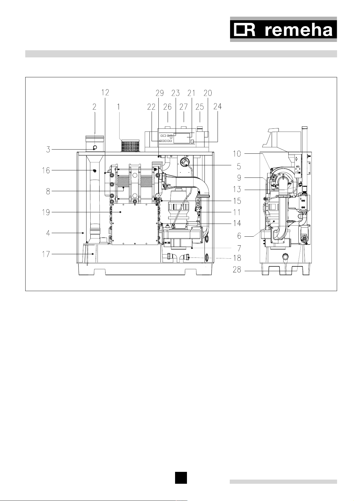
Fig. 02 Cut away view of Remeha Gas 210 ECO (160
kW model shown)
1. air supply
2. flue gas outlet
3. combustion test point (O
/CO2)
2
4. sealed air box
5. differential air pressure switch (LD2)
6. IMS gas-air ratio control
7. air supply fan
8. pre-mix, fibre faced burner
9. combined ignition/ionisation probe
10. sight glass
11. gas valve multiblock (with governor)
12. cast aluminium, sectional heat exchanger
13. temperature sensor - flow
14. temperature sensor - return
15. temperature sensor - heat exchanger
16. temperature sensor - flue gas
17. drain pan (condensate)
18. condensate connection
19. heat exchanger inspection hatch
20. instrument panel
21. facility for incorporating a rematic® weather
compensator (optional)
22. boiler setting keys
23. read-out display and reset key
24. on/off switch
25. gas connection
26. flow connection
27. return connection (standard)
28. drain cock and optional second return connection
(when fitted) or optional low level return connection
instead of standard return connection
29. connection for optional thermostat pocket (for use
with external sequence control).
7

3.2 Operation principle
Combustion air is drawn into the closed air box through
the air inlet from the plant room (open flued) or from
outside via the eccentric flue system (room sealed) by
an air supply fan.
On the inlet side of the fan is a specially designed IMS
(Integrated Mixing System) gas / air ratio control unit
which takes gas from the gas valve multiblock and
mixes it in the correct proportions with the incoming air.
The IMS-system includes regular auto-calibration (every
12 hours), which guarantees a constant air/gas ratio.
Therefore this mechanical mixing system ensures the
correct mixture is delivered to the pre-mix burner at all
times.
Depending on demand (under the dictates of flow/
return sensor and other external/internal control inputs)
the 'abc®' system determines the boiler output, which
directly controls the volume of mixed gas and air to the
premix burner. This mixture is initially ignited by the
combined ignition/ionisation probe, which monitors the
state of the flame. Should the flame be unstable or not
ignite within the pre-set safety time cycle the controls
will (after 5 attempts) shut the boiler down requiring
manual intervention to reset the boiler. The digital display will indicate a flashing fault code confirming the
reason for the failure.
The products of combustion in the form of hot flue gases
are forced through the heat exchanger transferring their
heat to the system water (the flue gas temperature is
reduced to approximately 5°C above the temperature of
the system return water). Then they are discharged via
the condensate collector, vertically through the 150 mm
connection to atmosphere.
Because of the low flue gas exit temperature there will
be a vapour cloud formed at the flue gas terminal - this
is not smoke, simply water vapour formed during the
combustion process.
If the controls allow the flow and therefore return temperature to fall below dew point (55°C) this water vapour
will begin to condense out in the boiler, transferring its
latent heat into the system water, increasing the output
of the boiler without increasing the gas consumption.
Condensation formed within the boiler and flue system
is discharged from the boiler to an external drain via the
drain pan / siphon supplied.
The boiler can be supplied, as an option with a
second (fixed temperature) return connection. This
additional connection enables the boiler to make full use
of its condensing ability whilst accepting both fixed and
variable temperature returns from the same system.
Fig. 01
Remeha Gas 210 ECO
8
4 TECHNICAL DATA AND DIMENSIONS
4.1 Dimensions
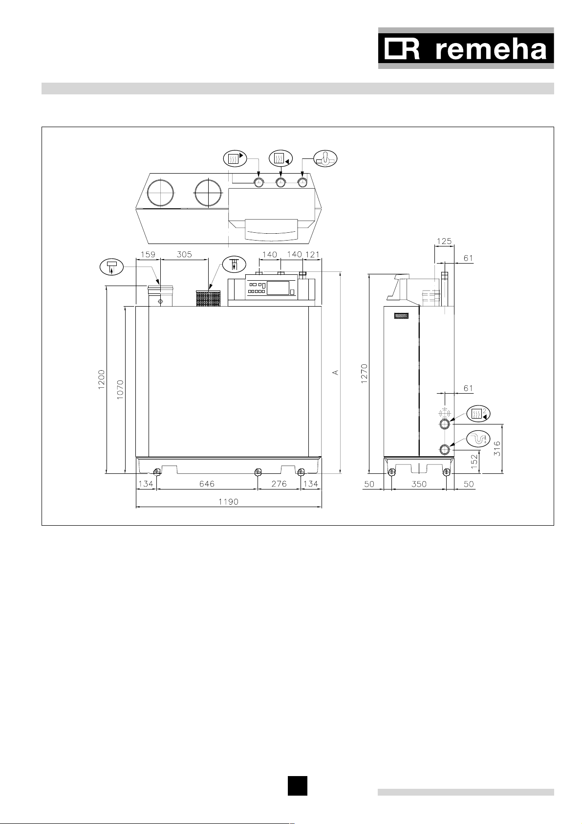
Fig. 03 View drawings
É Flow connection 80, 120 en 160 kW: 1¼" BSP (m) ; 200 kW: 1½” BSP (m)
Ê Return connection (standard) 80, 120 en 160 kW: 1¼" BSP (m) ; 200 kW: 1½” BSP (m)
Ï Gas connection 1¼" BSP (m)
Ò Condensate connection 32 mm o/d (plastic)
Ñ Flue gas connection 150 mm i/d
Ð Combustion air supply connection 150 mm i/d
Ì Second return connection* 1¼" BSP (m) (optional).
Height A 80, 120 en 160 kW: 1290 mm; 200 kW: 1305 mm
*or optional low level return connection instead of standard return connection
9
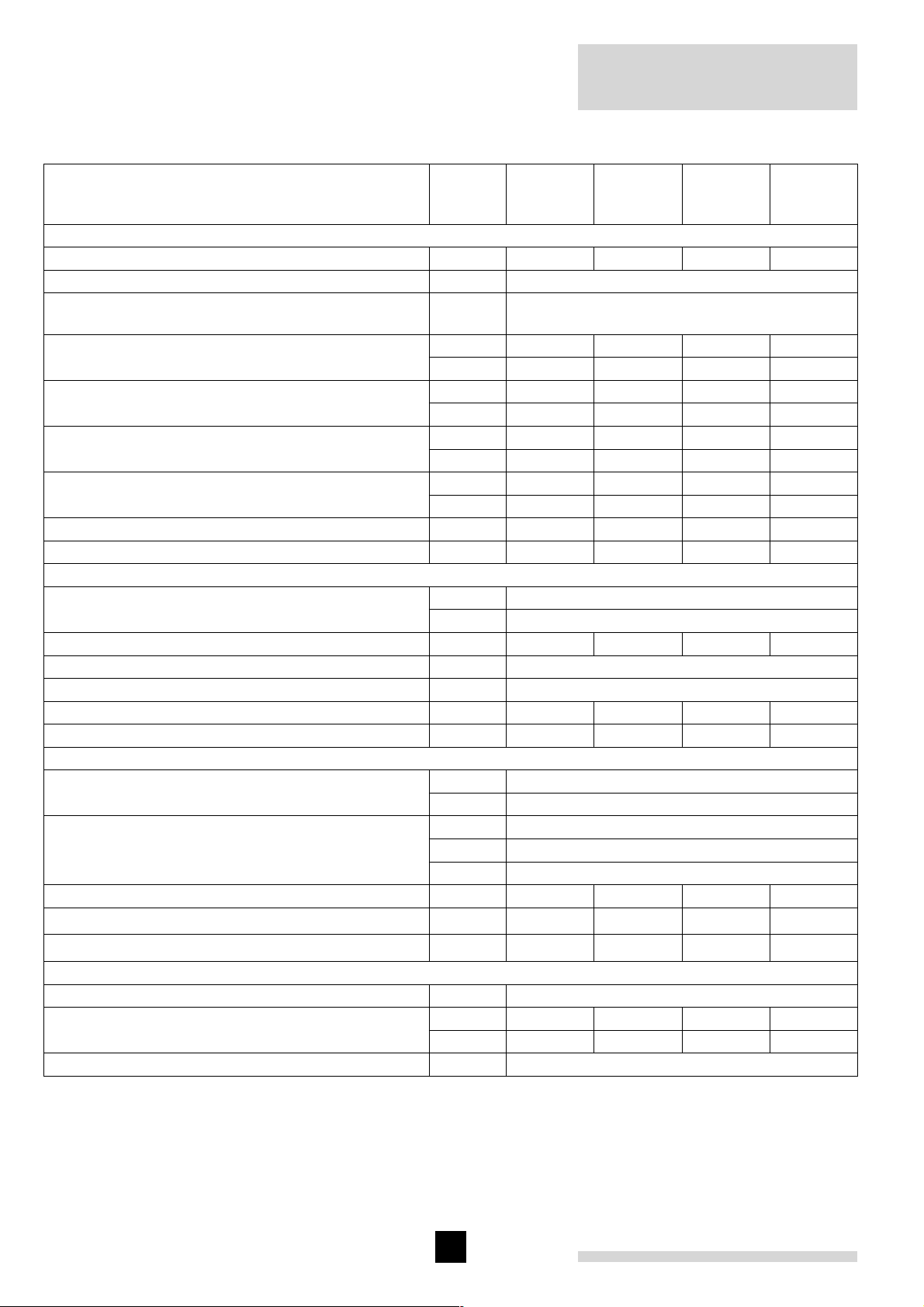
4.2 Technical data
Remeha Gas 210 ECO
Remeha
Boiler type
General
Number of sections qty. 3456
Casing Colour BS RAL 2002 (red) / 9023 (grey)
Boiler control options
(external input, two wire control)
Nominal output (80/60°C) Pn min. kW 8 12 16 20
max. kW 80 120 160 200
Nominal output (40/30°C) Pn min. kW 8.9 13.5 18.1 22.7
max. kW 86 129 171 214
Nominal input (GCV / Hs) Qn min. kW 9.3 14 18.7 23.3
max. kW 90.6 135.6 181.1 227
Nominal input (NCV / Hi) Qn min. kW 8.4 12.6 16.8 21
max. kW 81.5 122 163 204
Weight dry kg 130 150 170 200
Noise level at 1m from boiler, room sealed dBA ≤ 57 ≤ 59
Gas and Flue
Inlet pressure gas min. mbar 17
max. mbar 50
Gas consumption (natural gas) m3/h 8.6 12.9 17.2 21.6
NOX-emission mg/kWh < 35
NOX-emission (O2 = 0%, dry) ppm < 20
Residual fan duty Pa 115 100 100 140
Flue gas mass kg/h 137 205 274 343
Water side
Flow temperature max. °C 110
operating °C 20 - 90
Operating pressure - open vented min. bar 0.3
- closed min. bar 0.8
PMS max. bar 6
Water contents liter 12 16 20 24
Water resistance at 11°C dT
Water resistance at 20°C dT
Electrical
Main supply V / Hz 230 / 1 / 50
Power consumption min. Watt 68 58 69 75
max. Watt 92 84 110 160
Insulation class IP 20
Table 01 Technical data
mbar 496 446 536 720
mbar 150 135 162 180
Gas 210
ECO - 80
On/off, High/low, Analog 0-10V Communicating
Remeha
Gas 210
ECO - 120
Modulation
Remeha
Gas 210
ECO - 160
Remeha
Gas 210
ECO - 200
10

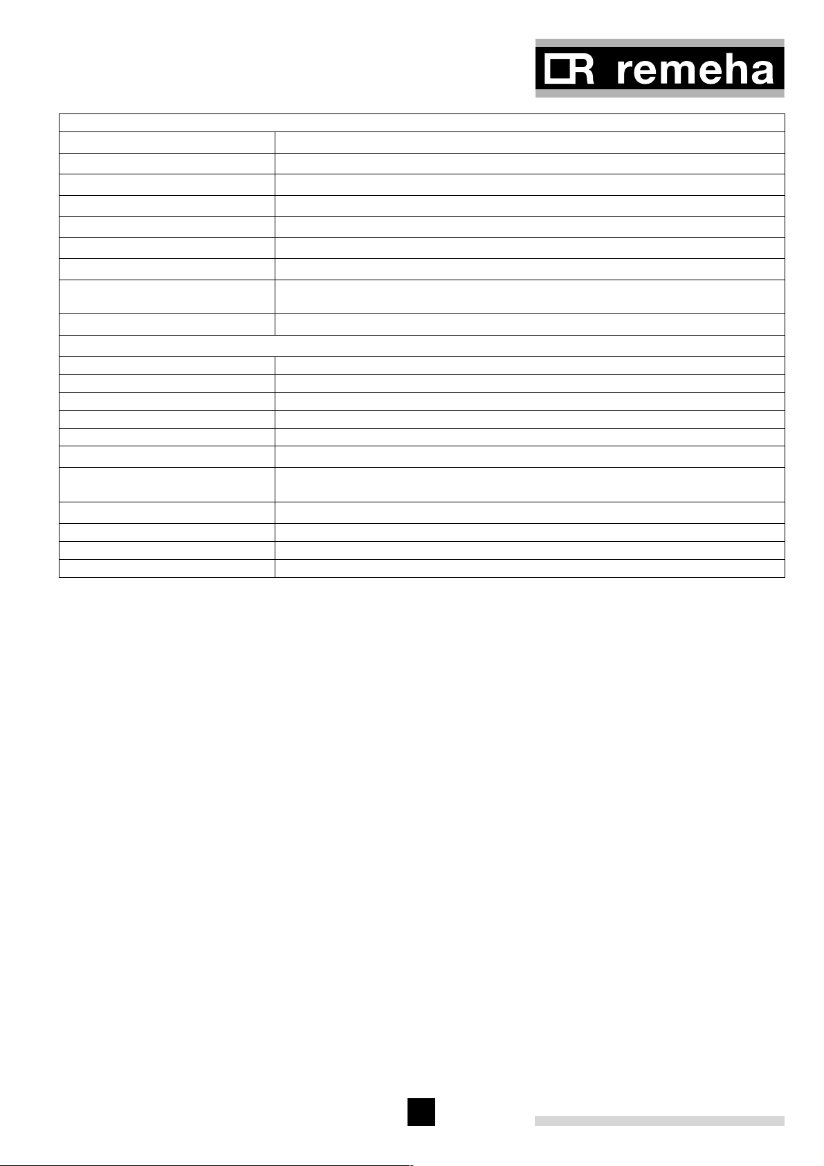
4.3 Quotation specifications
- Cast aluminium - sectional pre-mix gas fired boiler
- Sectional heat exchanger manufactured from cast
aluminium
- Maximum operating pressure of 6 bar
- Maximum operating temperature of 90°C
- Ultra low NO
(max. 20 ppm, O2= 0%, dry)
X
- Pre-mix, fully modulating (10-100%) gas burner with
unique IMS gas/air ratio control for maximum efficiency
- Intelligent advanced boiler control 'abc®' c/w a comprehensive operating, service and fault diagnostic
facility
- No minimum flow requirement
- Available as conventional flue or room sealed operation
- Capable of remote BMS control (0-10V modulating,
on/off and high/low option)
- Socket for advanced service diagnostics (for PC connection)
- Supplied fully factory assembled and tested
- Powder coated enamel steel casing BS RAL colour
2002 (red) / 9023 (grey)
- Sealed air box construction for maximum safety
- Suitable for use with Natural gas
- Supplied as standard with on/off switch, temperature
indication, flow, return, heat exchanger block and flue
gas sensors and hours run indication
- Supplied as standard with indicating module No. 1
lockout indication (Volt free), shutdown indication (Volt
free), boiler on indication (24 Volt AC)
- Efficiencies up to 109% (NCV / Hi)
- Manufactured to ISO 9001
- CE approved.
4.4 Optional Accessories
- Modulating weather-compensated / optimising boiler
controls for single and multiple installations
- Thermostat pocket
- Second return connection
- Water pressure sensor
- Air supply filter c/w air supply connecting piece (for
use during building construction)
- Vertical room sealed terminal c/w air supply connecting piece
- Indicating module No. 2 indicating operation, boiler on
and high fire (Volt free)
- Recom communication kit (includes CD-rom, interface
and wiring)
- Interface for communication with several boiler controls (see par. 9.4)
- Special cleaning tool
- Valve leak proving system
- Minimum gas pressure switch
- Low level return connection.
11

5 EFFICIENCY INFORMATION
Remeha Gas 210 ECO
5.1 Annual efficiency
Up to 108.2% at Hi (up to 97% at Hs) at an average
water temperature of 35°C (40/30°C).
5.2 Heat to water efficiency
a. Up to 98% at Hi (88% at Hs) at an average water
temperature of 70°C (80/60ºC).
b. Up to 109% at Hi (98% at Hs) at an average water
temperature of 35°C (40/30ºC).
6 APPLICATION INFORMATION
The Gas 210 ECO can be used on all new and refurbishment projects in both single and multiple configurations. Conventional and room sealed flue system
capability means that the boiler can be sited almost anywhere within a building. The Remeha range of weather
compensators (options) are able to communicate
7 CONTROL AND SAFETY EQUIPMENT
5.3 Standing losses
< 0.3% at Hi (0.33% at Hs) at an average water temperature of 45°C.
i NCV = Hi, GCV = Hs
directly with the boiler controls to make full use of its
fully modulating feature, ensuring that the boiler closely
matches the system demand at all times. External control systems (BMS) can be interfaced with the boiler to
provide on/off - high/low or modulating (0-10V) control
options.
7.1 The instrument panel
7.1.1 General
The boiler is supplied with a standard set of defaults
pre-programmed for normal operation but can be
tailored by the Engineer to suit most site conditions.
These values are set and read using the built in control
panel or with a note book computer (with optional
software and interface).
For security the control has three levels of access:
1. User level - free access
2. Service level - access with service code by qualified
personnel
3. Factory level - access by PC with factory code
(Remeha only).
7.1.2 Layout of the instrument panel
The instrument panel consists of the following components (see Fig. 04 and Table 02):
1 Operation switch
2 PC/ PDA connection for Recom setting and
monitoring
3 Facility for incorporating an optimising / weather
compensator
The functions of keys and displays (letters a - h) are
explained in Table 02.
Fig. 04 Instrument panel
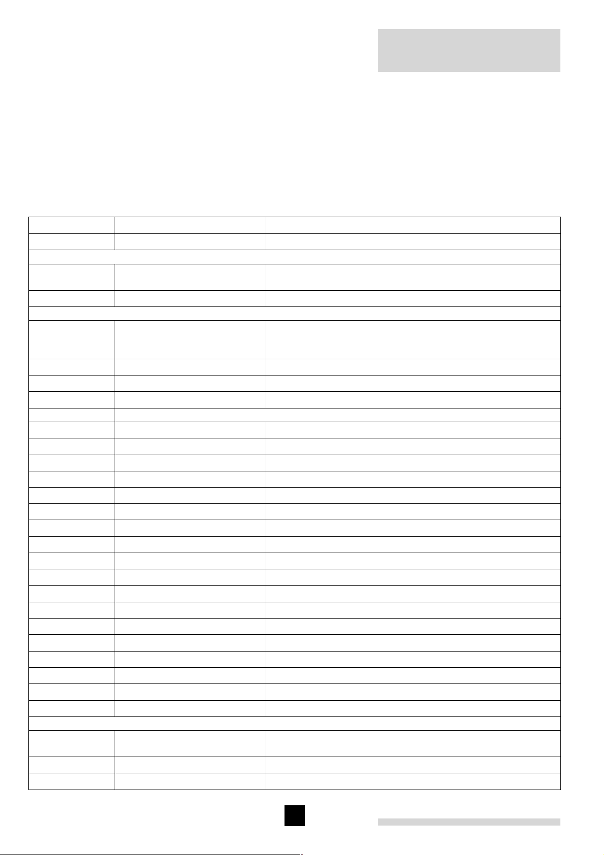
12
a. code-display
Indicates on user level:
Additional indication on service
level:
b. t-display
Indicates: temperatures
c. reset-key: to reset boiler after a lockout
d. m-key:
e. s-key:
f. e-key:
g. [+]-key: program function: to select a higher setting
h. [-]-key: program function: to select a lower setting
h. [-]-key held for 2 seconds switch function: manual override (hand/auto)
Table 02 Instrument panel functions
operating mode - 1 digit or letter
setting mode - ! digit or letter with dot
read-out mode - ! digit or letter with flashing dot
shut-off mode - letter b
forced full load - letter h
forced part load - letter l
test phase IMS - letter t
failure mode - 1 digit flashes
boiler run information mode - successively 1 + , + .
settings
shut-off codes
lockout codes
program function: key to select the required mode (mode-key)
program function: key to select the required program within the selected mode
(step-key)
program function: key to save the settings (store-key)
7.1.3 Indication LED's
The instrument panel has two indicating LED's.
1. The LED above the [-]-key (in the h-symbol) when
illuminated green confirms the boiler is in manual
override (see par. 7.1.4).
2. The LED above the [+]-key (in the 0-symbol) when
illuminated green confirms that the IMS system is
completely closed (rest position).
7.1.4 Manual override (hand/auto or forced modes
'high' and 'low')
Some of the keys on the instrument panel have a double function.
- Normal function - program input (see par. 7.5 and
7.6)
- Manual override - (during these modes as described
below the flow temperature cannot exceed its pre-set
maximum).
Hand/auto
When the [-]-key is pressed and held for 2 seconds the
boiler will run, even if external controls are not calling for
heat. The green LED above this key (in the h-symbol)
will illuminate indicating manual override.
By pressing and holding for 2 seconds the [-]-key, the
boiler will return to normal (auto control).
g Attention: A (system) pump that isn't
connected to the terminal strip of the boiler control
will not be activated!
Forced mode 'high' (h [[)
By pressing the m and [+]-key simultaneously in operating mode during 2 seconds, the boiler will run at
maximum power. The letter h will now appear on the
display.
By pressing the [+]- and [-]-keys simultaneously, the
boiler will return to operating mode.
Following a manual override the boiler will return to
normal (auto control) if no keys are used within a
15-minute period.
Forced mode 'low' (l [[)
By pressing the m and [-]-key simultaneously in operating mode, the boiler will run at minimum power. The
letter l will now appear on the display.
By pressing the [+]- and [-]-keys simultaneously, the
boiler will return to operating mode.
Following a manual override the boiler will return to normal (auto control) if no keys are used within a 15-minute
period.
13
Remeha Gas 210 ECO
7.1.5 Display of values with more than two digits
The display has only two digits available therefore values over this are displayed as follows:
- negative values will be indicated by a dot behind the
last digit e.g. 1) = -10
- values from 00 to 99 will be indicated without any
punctuation marks
- values from 100 to 199 will be indicated by a dot
between both digits e.g. )0 = 100, !0 = 110,
(9 = 199
press the m-key press the s-key
Operating mode,
see par. 7.3
Setting mode,
see par. 7.5 and
7.6
code-display
only digit or letter
0 - 9, h, l, b, t
digit or letter with dot
!
@
A
service engineer level only:
$
%
^
&
*
(
a
B
C
D
E
F
G
H
I
J
L
P
t-display
Flow temperature, shut-off code
Flow temperature setpoint
Pump run on time
Boiler control setting
Low fire start point as percentage
Boiler output as % to indicate high fire*
Maximum output
Forced part load
Forced part load running time
Cycling prevention delay-time
Start point for 0 Volt analogue signal
End point for 10 Volt analogue signal
n/a
n/a
dT from control stop point to start point
n/a
High limit temperature setpoint
Modulation start point dT
Minimum water pressure*
Adjustments options/accessories
n/a
Boiler type, factory set
- values from 200 to 299 will be indicated by a dot
behind every digit e.g. )) = for 200, !) = 210,
(( = 299
- values over 300 will be indicated by showing the
thousands, hundreds, tens and units in separate alternating pairs.
7.2 Flow diagram control system
Read-out mode,
see par. 7.7
digit or letter with flashing dot
!
@
Actual flow temperature
Actual return temperature
14
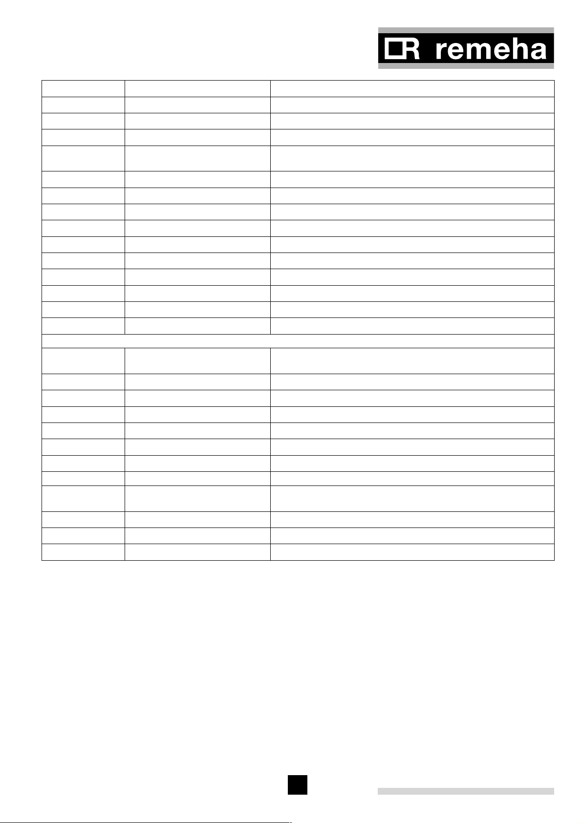
#
$
%
^
&
*
(
A
B
C
D
E
F
G
H
Actual flue gas temperature
Actual outdoor temperature (with outside temperature sensor)
Actual heat exchanger temperature
Flow temperature (setpoint)
Actual heat demand status and differential air pressure switch
position
Actual open to close time IMS
Requested output
Calculated or actual output
Status IMS
Actual valve position IMS
Actual water pressure*
Actual ∆p over burner and heat exchanger*
Actual fan speed
Actual ionisation level
Minimum position IMS
Failure mode,
see par. 7.8
Counter mode,
see par. 7.9
* Note: Only active when optional module / sensor is fitted.
Table 03 Flow diagram control system
7.3 Operating mode (x [[)
During normal operation the code-display shows the
status (position in cycle) of the boiler, with the t-dis-
play indicating the actual flow temperature.
digit flashes digits flash
1
2
3
4
5
6
digit + , + .
1, ,, .
2, ,, .
3, ,, .
Failure code (chapter 11)
Operating mode during failure (par. 7.3)
Flow temperature during failure
Return temperature during failure
Flue gas temperature during failure
Position of IMS during failure
digits flash
Number of operating hours burner
Number of successful ignition attempts
Total number of start attempts
The digits or letters in the code-display have the following meaning:
15
 Loading...