

REMEHA Gas 210 ECO PRO Series, Gas 210-200 ECO PRO, Gas 210-160 ECO PRO, Gas 210-80 ECO PRO, Gas 210-120 ECO PRO Installation, User And Service Manual
United Kingdom
en
Installation, User and Service Manual
High-efficiency floor-standing gas boiler
Gas 210 ECO PRO
210-80 – 210-120 – 210-160 – 210-200

Dear Customer,
Thank you very much for buying this appliance.
Please read through the manual carefully before using the product, and keep it in a safe place for later reference. In order to
ensure continued safe and efficient operation we recommend that the product is serviced regularly. Our service and customer
service organisation can assist with this.
We hope you enjoy years of problem-free operation with the product.

Contents
114494 - v.05 - 06022018 3
Contents
1 Safety . . . . . . . . . . . . . . . . . . . . . . . . . . . . . . . . . . . . . . . . . . . . . . . . . . . . . . . . . . . . . . . . . . . . . . . . . . . . . . . . . . . . . . . . . . . . 6
1.1 General safety instructions . . . . . . . . . . . . . . . . . . . . . . . . . . . . . . . . . . . . . . . . . . . . . . . . . . . . . . . . . . . . . . . . . . . . . . . 6
1.2 Recommendations . . . . . . . . . . . . . . . . . . . . . . . . . . . . . . . . . . . . . . . . . . . . . . . . . . . . . . . . . . . . . . . . . . . . . . . . . . . . . 8
1.3 Specific safety instructions . . . . . . . . . . . . . . . . . . . . . . . . . . . . . . . . . . . . . . . . . . . . . . . . . . . . . . . . . . . . . . . . . . . . . . 10
1.3.1 Additional guidelines . . . . . . . . . . . . . . . . . . . . . . . . . . . . . . . . . . . . . . . . . . . . . . . . . . . . . . . . . . . . . . . . . . . 10
1.4 Liabilities . . . . . . . . . . . . . . . . . . . . . . . . . . . . . . . . . . . . . . . . . . . . . . . . . . . . . . . . . . . . . . . . . . . . . . . . . . . . . . . . . . . . 10
1.4.1 Manufacturer's liability . . . . . . . . . . . . . . . . . . . . . . . . . . . . . . . . . . . . . . . . . . . . . . . . . . . . . . . . . . . . . . . . . . 10
1.4.2 Installer's liability . . . . . . . . . . . . . . . . . . . . . . . . . . . . . . . . . . . . . . . . . . . . . . . . . . . . . . . . . . . . . . . . . . . . . . 10
1.4.3 User's liability . . . . . . . . . . . . . . . . . . . . . . . . . . . . . . . . . . . . . . . . . . . . . . . . . . . . . . . . . . . . . . . . . . . . . . . . .11
2 About this manual . . . . . . . . . . . . . . . . . . . . . . . . . . . . . . . . . . . . . . . . . . . . . . . . . . . . . . . . . . . . . . . . . . . . . . . . . . . . . . . . . . 12
2.1 General . . . . . . . . . . . . . . . . . . . . . . . . . . . . . . . . . . . . . . . . . . . . . . . . . . . . . . . . . . . . . . . . . . . . . . . . . . . . . . . . . . . . . 12
2.2 Additional documentation . . . . . . . . . . . . . . . . . . . . . . . . . . . . . . . . . . . . . . . . . . . . . . . . . . . . . . . . . . . . . . . . . . . . . . . 12
2.3 Symbols used in the manual . . . . . . . . . . . . . . . . . . . . . . . . . . . . . . . . . . . . . . . . . . . . . . . . . . . . . . . . . . . . . . . . . . . . .12
3 Technical specifications . . . . . . . . . . . . . . . . . . . . . . . . . . . . . . . . . . . . . . . . . . . . . . . . . . . . . . . . . . . . . . . . . . . . . . . . . . . . . 13
3.1 Homologations . . . . . . . . . . . . . . . . . . . . . . . . . . . . . . . . . . . . . . . . . . . . . . . . . . . . . . . . . . . . . . . . . . . . . . . . . . . . . . . 13
3.1.1 Certifications . . . . . . . . . . . . . . . . . . . . . . . . . . . . . . . . . . . . . . . . . . . . . . . . . . . . . . . . . . . . . . . . . . . . . . . . . 13
3.1.2 Unit categories . . . . . . . . . . . . . . . . . . . . . . . . . . . . . . . . . . . . . . . . . . . . . . . . . . . . . . . . . . . . . . . . . . . . . . . .13
3.1.3 Directives . . . . . . . . . . . . . . . . . . . . . . . . . . . . . . . . . . . . . . . . . . . . . . . . . . . . . . . . . . . . . . . . . . . . . . . . . . . .13
3.1.4 Factory test . . . . . . . . . . . . . . . . . . . . . . . . . . . . . . . . . . . . . . . . . . . . . . . . . . . . . . . . . . . . . . . . . . . . . . . . . . 13
3.2 Technical data . . . . . . . . . . . . . . . . . . . . . . . . . . . . . . . . . . . . . . . . . . . . . . . . . . . . . . . . . . . . . . . . . . . . . . . . . . . . . . . .13
3.3 Dimensions and connections . . . . . . . . . . . . . . . . . . . . . . . . . . . . . . . . . . . . . . . . . . . . . . . . . . . . . . . . . . . . . . . . . . . . 16
3.4 Electrical diagram . . . . . . . . . . . . . . . . . . . . . . . . . . . . . . . . . . . . . . . . . . . . . . . . . . . . . . . . . . . . . . . . . . . . . . . . . . . . . 17
4 Description of the product . . . . . . . . . . . . . . . . . . . . . . . . . . . . . . . . . . . . . . . . . . . . . . . . . . . . . . . . . . . . . . . . . . . . . . . . . . . . 19
4.1 General description . . . . . . . . . . . . . . . . . . . . . . . . . . . . . . . . . . . . . . . . . . . . . . . . . . . . . . . . . . . . . . . . . . . . . . . . . . . .19
4.2 Operating principle . . . . . . . . . . . . . . . . . . . . . . . . . . . . . . . . . . . . . . . . . . . . . . . . . . . . . . . . . . . . . . . . . . . . . . . . . . . . 19
4.2.1 Gas/air regulation . . . . . . . . . . . . . . . . . . . . . . . . . . . . . . . . . . . . . . . . . . . . . . . . . . . . . . . . . . . . . . . . . . . . . 19
4.2.2 Control . . . . . . . . . . . . . . . . . . . . . . . . . . . . . . . . . . . . . . . . . . . . . . . . . . . . . . . . . . . . . . . . . . . . . . . . . . . . . . 19
4.2.3 Circulation pump . . . . . . . . . . . . . . . . . . . . . . . . . . . . . . . . . . . . . . . . . . . . . . . . . . . . . . . . . . . . . . . . . . . . . . 19
4.3 Gas 210 ECO PRO main components . . . . . . . . . . . . . . . . . . . . . . . . . . . . . . . . . . . . . . . . . . . . . . . . . . . . . . . . . . . . . 20
4.4 Control panel description . . . . . . . . . . . . . . . . . . . . . . . . . . . . . . . . . . . . . . . . . . . . . . . . . . . . . . . . . . . . . . . . . . . . . . . 20
4.5 Accessories and options . . . . . . . . . . . . . . . . . . . . . . . . . . . . . . . . . . . . . . . . . . . . . . . . . . . . . . . . . . . . . . . . . . . . . . . . 21
5 Before installation . . . . . . . . . . . . . . . . . . . . . . . . . . . . . . . . . . . . . . . . . . . . . . . . . . . . . . . . . . . . . . . . . . . . . . . . . . . . . . . . . . 22
5.1 Installation regulations . . . . . . . . . . . . . . . . . . . . . . . . . . . . . . . . . . . . . . . . . . . . . . . . . . . . . . . . . . . . . . . . . . . . . . . . . 22
5.2 Choice of the location . . . . . . . . . . . . . . . . . . . . . . . . . . . . . . . . . . . . . . . . . . . . . . . . . . . . . . . . . . . . . . . . . . . . . . . . . . 22
5.2.1 Data plate . . . . . . . . . . . . . . . . . . . . . . . . . . . . . . . . . . . . . . . . . . . . . . . . . . . . . . . . . . . . . . . . . . . . . . . . . . . 22
5.2.2 Location of the boiler . . . . . . . . . . . . . . . . . . . . . . . . . . . . . . . . . . . . . . . . . . . . . . . . . . . . . . . . . . . . . . . . . . . 23
5.3 Transport . . . . . . . . . . . . . . . . . . . . . . . . . . . . . . . . . . . . . . . . . . . . . . . . . . . . . . . . . . . . . . . . . . . . . . . . . . . . . . . . . . . .24
5.4 Unpacking & initial preparation . . . . . . . . . . . . . . . . . . . . . . . . . . . . . . . . . . . . . . . . . . . . . . . . . . . . . . . . . . . . . . . . . . . 24
6 Installation . . . . . . . . . . . . . . . . . . . . . . . . . . . . . . . . . . . . . . . . . . . . . . . . . . . . . . . . . . . . . . . . . . . . . . . . . . . . . . . . . . . . . . . . 25
6.1 General . . . . . . . . . . . . . . . . . . . . . . . . . . . . . . . . . . . . . . . . . . . . . . . . . . . . . . . . . . . . . . . . . . . . . . . . . . . . . . . . . . . . . 25
6.2 Hydraulic connections . . . . . . . . . . . . . . . . . . . . . . . . . . . . . . . . . . . . . . . . . . . . . . . . . . . . . . . . . . . . . . . . . . . . . . . . . .25
6.2.1 Rinsing the system . . . . . . . . . . . . . . . . . . . . . . . . . . . . . . . . . . . . . . . . . . . . . . . . . . . . . . . . . . . . . . . . . . . . 25
6.2.2 Connecting the heating circuit . . . . . . . . . . . . . . . . . . . . . . . . . . . . . . . . . . . . . . . . . . . . . . . . . . . . . . . . . . . . 25
6.2.3 Connecting the condensate discharge pipe . . . . . . . . . . . . . . . . . . . . . . . . . . . . . . . . . . . . . . . . . . . . . . . . . .26
6.3 Gas connection . . . . . . . . . . . . . . . . . . . . . . . . . . . . . . . . . . . . . . . . . . . . . . . . . . . . . . . . . . . . . . . . . . . . . . . . . . . . . . . 26
6.4 Air supply/flue gas connections . . . . . . . . . . . . . . . . . . . . . . . . . . . . . . . . . . . . . . . . . . . . . . . . . . . . . . . . . . . . . . . . . . 27
6.4.1 Classification . . . . . . . . . . . . . . . . . . . . . . . . . . . . . . . . . . . . . . . . . . . . . . . . . . . . . . . . . . . . . . . . . . . . . . . . . 27
6.4.2 Requirements for shaft for C93 . . . . . . . . . . . . . . . . . . . . . . . . . . . . . . . . . . . . . . . . . . . . . . . . . . . . . . . . . . . .28
6.4.3 Material . . . . . . . . . . . . . . . . . . . . . . . . . . . . . . . . . . . . . . . . . . . . . . . . . . . . . . . . . . . . . . . . . . . . . . . . . . . . . 29
6.4.4 Dimensions of flue gas outlet pipe . . . . . . . . . . . . . . . . . . . . . . . . . . . . . . . . . . . . . . . . . . . . . . . . . . . . . . . . .30
6.4.5 Length of the air and flue gas pipes . . . . . . . . . . . . . . . . . . . . . . . . . . . . . . . . . . . . . . . . . . . . . . . . . . . . . . . .30
6.4.6 Additional guidelines . . . . . . . . . . . . . . . . . . . . . . . . . . . . . . . . . . . . . . . . . . . . . . . . . . . . . . . . . . . . . . . . . . . 33
6.4.7 Air/flue gas adapter . . . . . . . . . . . . . . . . . . . . . . . . . . . . . . . . . . . . . . . . . . . . . . . . . . . . . . . . . . . . . . . . . . . . 33
6.4.8 Connecting the flue gas outlet . . . . . . . . . . . . . . . . . . . . . . . . . . . . . . . . . . . . . . . . . . . . . . . . . . . . . . . . . . . . 33
6.4.9 Connecting the air supply . . . . . . . . . . . . . . . . . . . . . . . . . . . . . . . . . . . . . . . . . . . . . . . . . . . . . . . . . . . . . . . 34
6.5 Electrical connections . . . . . . . . . . . . . . . . . . . . . . . . . . . . . . . . . . . . . . . . . . . . . . . . . . . . . . . . . . . . . . . . . . . . . . . . . . 34
6.5.1 Recommendations . . . . . . . . . . . . . . . . . . . . . . . . . . . . . . . . . . . . . . . . . . . . . . . . . . . . . . . . . . . . . . . . . . . . .34
6.5.2 Control unit . . . . . . . . . . . . . . . . . . . . . . . . . . . . . . . . . . . . . . . . . . . . . . . . . . . . . . . . . . . . . . . . . . . . . . . . . . 34
6.5.3 Accessing the terminal connectors and control PCBs . . . . . . . . . . . . . . . . . . . . . . . . . . . . . . . . . . . . . . . . . . 35

Contents
4 114494 - v.05 - 06022018
6.5.4 Connection options for the standard control PCB (PCU-01) . . . . . . . . . . . . . . . . . . . . . . . . . . . . . . . . . . . . . 36
6.5.5 Connection options for the 0–10 V PCB (IF-01) . . . . . . . . . . . . . . . . . . . . . . . . . . . . . . . . . . . . . . . . . . . . . . 37
6.5.6 Connection options for the PCB (SCU-X01) . . . . . . . . . . . . . . . . . . . . . . . . . . . . . . . . . . . . . . . . . . . . . . . . . 39
6.6 Filling the installation . . . . . . . . . . . . . . . . . . . . . . . . . . . . . . . . . . . . . . . . . . . . . . . . . . . . . . . . . . . . . . . . . . . . . . . . . . .39
6.6.1 Water treatment and water quality . . . . . . . . . . . . . . . . . . . . . . . . . . . . . . . . . . . . . . . . . . . . . . . . . . . . . . . . .39
6.6.2 Filling the siphon . . . . . . . . . . . . . . . . . . . . . . . . . . . . . . . . . . . . . . . . . . . . . . . . . . . . . . . . . . . . . . . . . . . . . . 40
6.6.3 Filling the installation . . . . . . . . . . . . . . . . . . . . . . . . . . . . . . . . . . . . . . . . . . . . . . . . . . . . . . . . . . . . . . . . . . . 40
7 Commissioning . . . . . . . . . . . . . . . . . . . . . . . . . . . . . . . . . . . . . . . . . . . . . . . . . . . . . . . . . . . . . . . . . . . . . . . . . . . . . . . . . . . . 41
7.1 Checklist before commissioning . . . . . . . . . . . . . . . . . . . . . . . . . . . . . . . . . . . . . . . . . . . . . . . . . . . . . . . . . . . . . . . . . . 41
7.1.1 Preparing the boiler for commissioning . . . . . . . . . . . . . . . . . . . . . . . . . . . . . . . . . . . . . . . . . . . . . . . . . . . . . 41
7.1.2 Gas circuit . . . . . . . . . . . . . . . . . . . . . . . . . . . . . . . . . . . . . . . . . . . . . . . . . . . . . . . . . . . . . . . . . . . . . . . . . . . 41
7.1.3 Hydraulic circuit . . . . . . . . . . . . . . . . . . . . . . . . . . . . . . . . . . . . . . . . . . . . . . . . . . . . . . . . . . . . . . . . . . . . . . . 41
7.1.4 Connections for the air and flue gas pipes . . . . . . . . . . . . . . . . . . . . . . . . . . . . . . . . . . . . . . . . . . . . . . . . . . 41
7.1.5 Electrical connections . . . . . . . . . . . . . . . . . . . . . . . . . . . . . . . . . . . . . . . . . . . . . . . . . . . . . . . . . . . . . . . . . . 41
7.2 Commissioning procedure . . . . . . . . . . . . . . . . . . . . . . . . . . . . . . . . . . . . . . . . . . . . . . . . . . . . . . . . . . . . . . . . . . . . . . 41
7.3 Gas settings . . . . . . . . . . . . . . . . . . . . . . . . . . . . . . . . . . . . . . . . . . . . . . . . . . . . . . . . . . . . . . . . . . . . . . . . . . . . . . . . . 42
7.3.1 Adaptation to a different gas type . . . . . . . . . . . . . . . . . . . . . . . . . . . . . . . . . . . . . . . . . . . . . . . . . . . . . . . . . 42
7.3.2 Checking/setting the combustion . . . . . . . . . . . . . . . . . . . . . . . . . . . . . . . . . . . . . . . . . . . . . . . . . . . . . . . . . .42
7.4 Final instructions . . . . . . . . . . . . . . . . . . . . . . . . . . . . . . . . . . . . . . . . . . . . . . . . . . . . . . . . . . . . . . . . . . . . . . . . . . . . . . 45
8 Operation . . . . . . . . . . . . . . . . . . . . . . . . . . . . . . . . . . . . . . . . . . . . . . . . . . . . . . . . . . . . . . . . . . . . . . . . . . . . . . . . . . . . . . . . .46
8.1 Use of the control panel . . . . . . . . . . . . . . . . . . . . . . . . . . . . . . . . . . . . . . . . . . . . . . . . . . . . . . . . . . . . . . . . . . . . . . . . 46
8.2 Shutdown . . . . . . . . . . . . . . . . . . . . . . . . . . . . . . . . . . . . . . . . . . . . . . . . . . . . . . . . . . . . . . . . . . . . . . . . . . . . . . . . . . . 46
8.3 Frost protection . . . . . . . . . . . . . . . . . . . . . . . . . . . . . . . . . . . . . . . . . . . . . . . . . . . . . . . . . . . . . . . . . . . . . . . . . . . . . . . 46
9 Settings . . . . . . . . . . . . . . . . . . . . . . . . . . . . . . . . . . . . . . . . . . . . . . . . . . . . . . . . . . . . . . . . . . . . . . . . . . . . . . . . . . . . . . . . . . 47
9.1 Description of Gas 210 ECO PRO parameters . . . . . . . . . . . . . . . . . . . . . . . . . . . . . . . . . . . . . . . . . . . . . . . . . . . . . . .47
9.2 Changing the parameters . . . . . . . . . . . . . . . . . . . . . . . . . . . . . . . . . . . . . . . . . . . . . . . . . . . . . . . . . . . . . . . . . . . . . . . 48
9.2.1 Setting the parameters in the Installer level . . . . . . . . . . . . . . . . . . . . . . . . . . . . . . . . . . . . . . . . . . . . . . . . . .49
9.3 Reading out measured values . . . . . . . . . . . . . . . . . . . . . . . . . . . . . . . . . . . . . . . . . . . . . . . . . . . . . . . . . . . . . . . . . . . 49
9.3.1 Reading current values . . . . . . . . . . . . . . . . . . . . . . . . . . . . . . . . . . . . . . . . . . . . . . . . . . . . . . . . . . . . . . . . . 49
9.3.2 Status and sub-status . . . . . . . . . . . . . . . . . . . . . . . . . . . . . . . . . . . . . . . . . . . . . . . . . . . . . . . . . . . . . . . . . . 50
10 Maintenance . . . . . . . . . . . . . . . . . . . . . . . . . . . . . . . . . . . . . . . . . . . . . . . . . . . . . . . . . . . . . . . . . . . . . . . . . . . . . . . . . . . . . . 52
10.1 General . . . . . . . . . . . . . . . . . . . . . . . . . . . . . . . . . . . . . . . . . . . . . . . . . . . . . . . . . . . . . . . . . . . . . . . . . . . . . . . . . . . . . 52
10.2 Standard inspection and maintenance operations . . . . . . . . . . . . . . . . . . . . . . . . . . . . . . . . . . . . . . . . . . . . . . . . . . . . 52
10.2.1 Checking the water pressure . . . . . . . . . . . . . . . . . . . . . . . . . . . . . . . . . . . . . . . . . . . . . . . . . . . . . . . . . . . . . 52
10.2.2 Checking the water quality . . . . . . . . . . . . . . . . . . . . . . . . . . . . . . . . . . . . . . . . . . . . . . . . . . . . . . . . . . . . . . .52
10.2.3 Checking the ionisation current . . . . . . . . . . . . . . . . . . . . . . . . . . . . . . . . . . . . . . . . . . . . . . . . . . . . . . . . . . . 52
10.2.4 Check the flue gas outlet/air supply connections . . . . . . . . . . . . . . . . . . . . . . . . . . . . . . . . . . . . . . . . . . . . . .52
10.2.5 Checking the combustion . . . . . . . . . . . . . . . . . . . . . . . . . . . . . . . . . . . . . . . . . . . . . . . . . . . . . . . . . . . . . . . 53
10.2.6 Cleaning the siphon . . . . . . . . . . . . . . . . . . . . . . . . . . . . . . . . . . . . . . . . . . . . . . . . . . . . . . . . . . . . . . . . . . . . 53
10.3 Specific maintenance work . . . . . . . . . . . . . . . . . . . . . . . . . . . . . . . . . . . . . . . . . . . . . . . . . . . . . . . . . . . . . . . . . . . . . . 53
10.3.1 Cleaning the fan . . . . . . . . . . . . . . . . . . . . . . . . . . . . . . . . . . . . . . . . . . . . . . . . . . . . . . . . . . . . . . . . . . . . . . .54
10.3.2 Clean heat exchanger . . . . . . . . . . . . . . . . . . . . . . . . . . . . . . . . . . . . . . . . . . . . . . . . . . . . . . . . . . . . . . . . . . 56
10.3.3 Cleaning the burner . . . . . . . . . . . . . . . . . . . . . . . . . . . . . . . . . . . . . . . . . . . . . . . . . . . . . . . . . . . . . . . . . . . . 57
10.3.4 Replacing the ionisation/ignition electrode . . . . . . . . . . . . . . . . . . . . . . . . . . . . . . . . . . . . . . . . . . . . . . . . . . 57
10.3.5 Reassembling the boiler . . . . . . . . . . . . . . . . . . . . . . . . . . . . . . . . . . . . . . . . . . . . . . . . . . . . . . . . . . . . . . . . 58
11 Troubleshooting . . . . . . . . . . . . . . . . . . . . . . . . . . . . . . . . . . . . . . . . . . . . . . . . . . . . . . . . . . . . . . . . . . . . . . . . . . . . . . . . . . . .59
11.1 Error codes . . . . . . . . . . . . . . . . . . . . . . . . . . . . . . . . . . . . . . . . . . . . . . . . . . . . . . . . . . . . . . . . . . . . . . . . . . . . . . . . . . 59
11.1.1 Blocking . . . . . . . . . . . . . . . . . . . . . . . . . . . . . . . . . . . . . . . . . . . . . . . . . . . . . . . . . . . . . . . . . . . . . . . . . . . . . 59
11.1.2 Lock out . . . . . . . . . . . . . . . . . . . . . . . . . . . . . . . . . . . . . . . . . . . . . . . . . . . . . . . . . . . . . . . . . . . . . . . . . . . . . 61
11.2 Blockage and fault memory . . . . . . . . . . . . . . . . . . . . . . . . . . . . . . . . . . . . . . . . . . . . . . . . . . . . . . . . . . . . . . . . . . . . . .65
12 Disposal . . . . . . . . . . . . . . . . . . . . . . . . . . . . . . . . . . . . . . . . . . . . . . . . . . . . . . . . . . . . . . . . . . . . . . . . . . . . . . . . . . . . . . . . . .66
12.1 Removal/recycling . . . . . . . . . . . . . . . . . . . . . . . . . . . . . . . . . . . . . . . . . . . . . . . . . . . . . . . . . . . . . . . . . . . . . . . . . . . . .66
13 Spare parts . . . . . . . . . . . . . . . . . . . . . . . . . . . . . . . . . . . . . . . . . . . . . . . . . . . . . . . . . . . . . . . . . . . . . . . . . . . . . . . . . . . . . . . 67
13.1 General . . . . . . . . . . . . . . . . . . . . . . . . . . . . . . . . . . . . . . . . . . . . . . . . . . . . . . . . . . . . . . . . . . . . . . . . . . . . . . . . . . . . . 67
13.2 Parts . . . . . . . . . . . . . . . . . . . . . . . . . . . . . . . . . . . . . . . . . . . . . . . . . . . . . . . . . . . . . . . . . . . . . . . . . . . . . . . . . . . . . . . 68
14 Appendix . . . . . . . . . . . . . . . . . . . . . . . . . . . . . . . . . . . . . . . . . . . . . . . . . . . . . . . . . . . . . . . . . . . . . . . . . . . . . . . . . . . . . . . . . 69
14.1 ErP information . . . . . . . . . . . . . . . . . . . . . . . . . . . . . . . . . . . . . . . . . . . . . . . . . . . . . . . . . . . . . . . . . . . . . . . . . . . . . . . 69
14.1.1 Product card . . . . . . . . . . . . . . . . . . . . . . . . . . . . . . . . . . . . . . . . . . . . . . . . . . . . . . . . . . . . . . . . . . . . . . . . . 69

Contents
114494 - v.05 - 06022018 5
14.2 Optional electrical connections . . . . . . . . . . . . . . . . . . . . . . . . . . . . . . . . . . . . . . . . . . . . . . . . . . . . . . . . . . . . . . . . . . . 69
14.2.1 Connection options for the control PCB (SCU-S01) . . . . . . . . . . . . . . . . . . . . . . . . . . . . . . . . . . . . . . . . . . . 69
14.2.2 Connection options for the PCB (SCU-X03) . . . . . . . . . . . . . . . . . . . . . . . . . . . . . . . . . . . . . . . . . . . . . . . . . 69
1 Safety
6 114494 - v.05 - 06022018
1 Safety
1.1 General safety instructions
For the installer:
Danger
If you smell gas:
1. Do not use naked flames, do not smoke and
do not operate electrical contacts or switches
(doorbell, lighting, motor, lift etc).
2. Shut off the gas supply.
3. Open the windows.
4. Trace possible leaks and seal them off imme
diately.
5. If the leak is upstream of the gas meter, notify
the gas company.
Danger
If you smell flue gases:
1. Switch the boiler off.
2. Open the windows.
3. Trace possible leaks and seal them off imme
diately.
Caution
After maintenance or repair work, check the en
tire heating installation to ensure that there are no
leaks.
For the end user:
1 Safety
114494 - v.05 - 06022018 7
Danger
If you smell gas:
1. Do not use naked flames, do not smoke and
do not operate electrical contacts or switches
(doorbell, lighting, motor, lift etc).
2. Shut off the gas supply.
3. Open the windows.
4. Report any leaks immediately.
5. Evacuate the property.
6. Contact a qualified installer.
Danger
If you smell flue gases:
1. Switch the boiler off.
2. Open the windows.
3. Report any leaks immediately.
4. Evacuate the property.
5. Contact a qualified installer.
Warning
Do not touch the flue gas pipes. Depending on
the boiler settings, the temperature of the flue gas
pipes can rise to over 60°C.
Warning
Do not touch radiators for long periods. Depend
ing on the boiler settings, the temperature of the
radiators can rise to over 60°C.
Warning
Be careful when using the domestic hot water.
Depending on the boiler settings, the temperature
of domestic hot water can rise to over 65°C.
Warning
The use of the boiler and the installation by you
as the end-user must be limited to the operations
described in this manual. All other actions may
only be undertaken by a qualified fitter/engineer.
Warning
The condensation drain must not be changed or
sealed. If a condensate neutralisation system is
used, the system must be cleaned regularly in ac
cordance with the instructions provided by the
manufacturer.
1 Safety
8 114494 - v.05 - 06022018
Caution
Ensure that the boiler is regularly serviced. Con
tact a qualified installer or arrange a maintenance
contract for the servicing of the boiler.
Caution
Only genuine spare parts may be used.
Important
Regularly check for the presence of water and
pressure in the heating installation.
1.2
Recommendations
Danger
This appliance can be used by children aged
eight and above and people with a physical, sen
sory or mental disability, or with a lack of experi
ence and knowledge, provided they are super
vised and instructed in how to use the appliance
in a safe manner and understand the associated
dangers. Children must not be allowed to play
with the appliance. Cleaning and user mainte
nance should not be carried out by children with
out adult supervision.
Warning
Installation and maintenance of the boiler must be
carried out by a qualified installer in accordance
with local and national regulations.
Warning
The installation and maintenance of the boiler
must be undertaken by a qualified installer in ac
cordance with the information in the supplied
manual, doing otherwise may result in dangerous
situations and/or bodily injury.
Warning
Removal and disposal of the boiler must be car
ried out by a qualified installer in accordance with
local and national regulations.
Warning
If the mains lead is damaged, it must be replaced
by the original manufacturer, the manufacturer's
dealer or another suitably skilled person to pre
vent hazardous situations from arising.
1 Safety
114494 - v.05 - 06022018 9
Warning
Always disconnect the mains supply and close
the main gas tap when working on the boiler.
Warning
Check the entire system for leaks after mainte
nance and servicing work.
Danger
For safety reasons, we recommend fitting smoke
and CO alarms at suitable places in your home.
Caution
Make sure the boiler can be reached at all
times.
The boiler must be installed in a frost-free area.
If the power cord is permanently connected, you
must always install a main bipolar switch with
an opening gap of at least 3 mm (BS EN
60335-1).
Drain the boiler and central heating system if
you are not going to use your home for a long
time and there is a chance of frost.
The frost protection does not work if the boiler is
out of operation.
The boiler protection only protects the boiler,
not the system.
Check the water pressure in the system regular
ly. If the water pressure is lower than 0.8 bar,
the system must be topped up (recommended
water pressure between 1.5 and 2 bar).
Important
Keep this document near to the boiler.
Important
Only remove the casing for maintenance and re
pair operations. Refit all panels when mainte
nance work and servicing are complete.
Important
Instruction and warning labels must never be re
moved or covered and must be clearly legible
throughout the entire service life of the boiler.
Damaged or illegible instructions and warning
stickers must be replaced immediately.
Important
Modifications to the boiler require the written ap
proval of Remeha.

1 Safety
10 114494 - v.05 - 06022018
1.3 Specific safety instructions
1.3.1 Additional guidelines
In addition to the legal requirements and guidelines, the
supplementary guidelines in this manual must also be
followed. Supplements or subsequent regulations and
guidelines that are valid at the time of installation shall
apply to all regulations and guidelines specified in this
manual.
1.4 Liabilities
1.4.1
Our products are manufactured in compliance with the
requirements of the various Directives applicable. They
are therefore delivered with the
documents necessary. In the interests of the quality of
our products, we strive constantly to improve them. We
therefore reserve the right to modify the specifications
given in this document.
Our liability as manufacturer may not be invoked in the
following cases:
Failure to abide by the instructions on installing the
appliance.
Failure to abide by the instructions on using the appli
ance.
Faulty or insufficient maintenance of the appliance.
1.4.2
The installer is responsible for the installation and initial
commissioning of the appliance. The installer must ob
serve the following instructions:
Manufacturer's liability
marking and any
Installer's liability
Read and follow the instructions given in the manuals
provided with the appliance.
Install the appliance in compliance with prevailing leg
islation and standards.
Carry out initial commissioning and any checks neces
sary.
Explain the installation to the user.
If maintenance is necessary, warn the user of the obli
gation to check the appliance and keep it in good
working order.
Give all the instruction manuals to the user.

1 Safety
114494 - v.05 - 06022018 11
1.4.3
User's liability
To guarantee optimum operation of the system, you
must abide by the following instructions:
Read and follow the instructions given in the manuals
provided with the appliance.
Call on a qualified professional to carry out installation
and initial commissioning.
Get your installer to explain your installation to you.
Have the required inspections and maintenance car
ried out by a qualified installer.
Keep the instruction manuals in good condition close
to the appliance.
2 About this manual
12 114494 - v.05 - 06022018
2 About this manual
2.1 General
This manual describes the installation, use and maintenance of the Gas
210 ECO PRO boiler. This manual is part of all the documentation sup
plied with the boiler.
2.2
2.3
Additional documentation
The following documentation is available in addition to this manual:
Installation and user manual for control panel
Water quality instructions
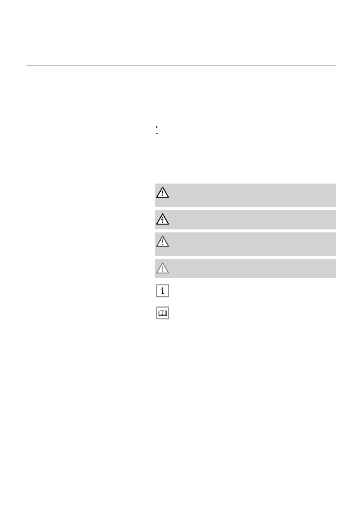
Symbols used in the manual
This manual uses various danger levels to draw attention to special in
structions. We do this to improve user safety, to prevent problems and to
guarantee correct operation of the appliance.
Danger
Risk of dangerous situations that may result in serious personal
injury.
Danger of electric shock
Risk of electric shock.
Warning
Risk of dangerous situations that may result in minor personal in
jury.
Caution
Risk of material damage.
Important
Please note: important information.
See
Reference to other manuals or pages in this manual.
3 Technical specifications
114494 - v.05 - 06022018 13
3.1 Homologations
3.1.1 Certifications
Tab.1 Certifications
CE identification number PIN 0085BS0132
Class NOx
(1)
6
3 Technical specifications
Type of connection B
(1) EN 15502–1
23P
C13, C33, C53, C63, C
93
3.1.2 Unit categories
Tab.2 Unit categories
Country Category Gas type Connection pressure (mbar)
Great Britain II
2H3P
G20 (H gas)
G31 (propane)
20
37-50
3.1.3 Directives
In addition to the legal requirements and guidelines, the supplementary
guidelines in this manual must also be followed.
Supplements or subsequent regulations and guidelines that are valid at
the time of installation shall apply to all regulations and guidelines speci
fied in this manual.
3.1.4 Factory test
Before leaving the factory, each boiler is optimally set and tested for:
Electrical safety.
Adjustment of (O2/CO2).
Water tightness.
Gas tightness.
Parameter setting.
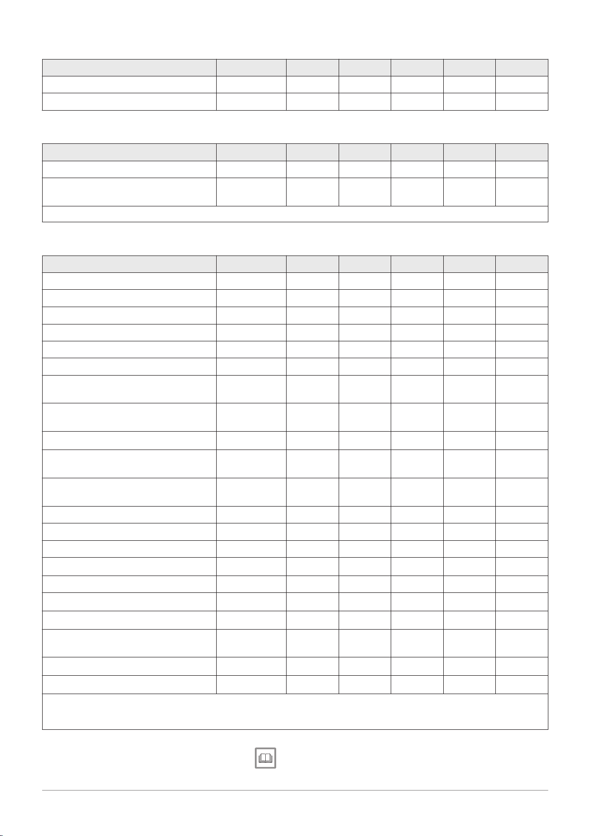
3.2
Technical data
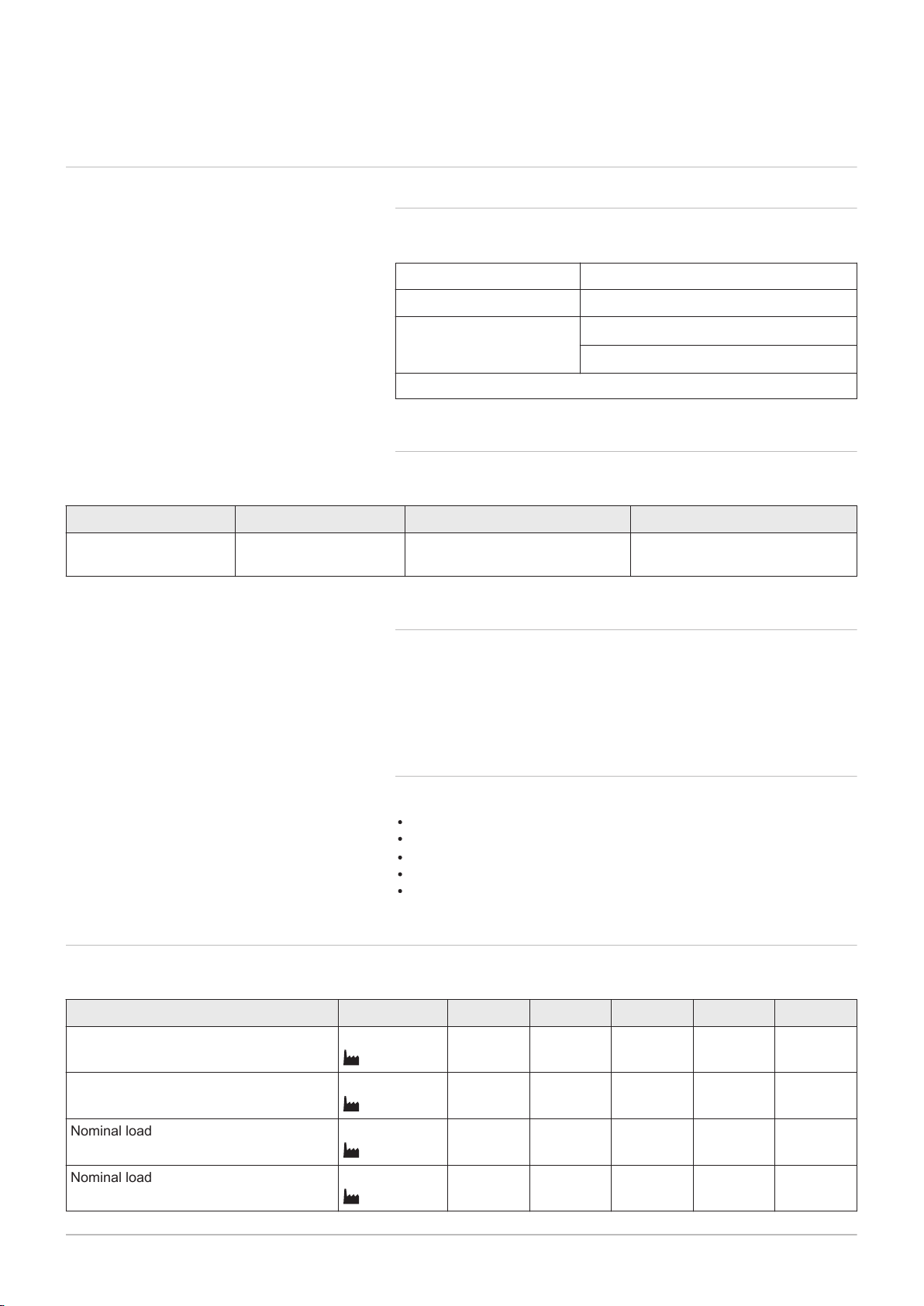
Tab.3 General
Gas 210 ECO PRO 210-80 210-120 210-160 210-200
Nominal output (Pn)
Central heating operation (80/60°C)
Nominal output (Pn)
Central heating operation (50/30°C)
Nominal load (Qnh)
Central heating operation (Hi)
Nominal load (Qnh)
Central heating operation (Hs)
min-max
(1)
min-max
(1)
min-max
(1)
min-max
(1)
kW 16 - 87
87
kW 18 - 93
93
kW 17 - 89
89
kW 19 - 99
99
22 - 115
115.0
24 - 129
129
23 - 123
123
26 - 137
137
29 - 166
166
33 - 179
179
31 - 170
170
34 - 189
189
39 - 200
200
44 - 217
217
41 - 205
205
46 - 228
228
3 Technical specifications
14 114494 - v.05 - 06022018
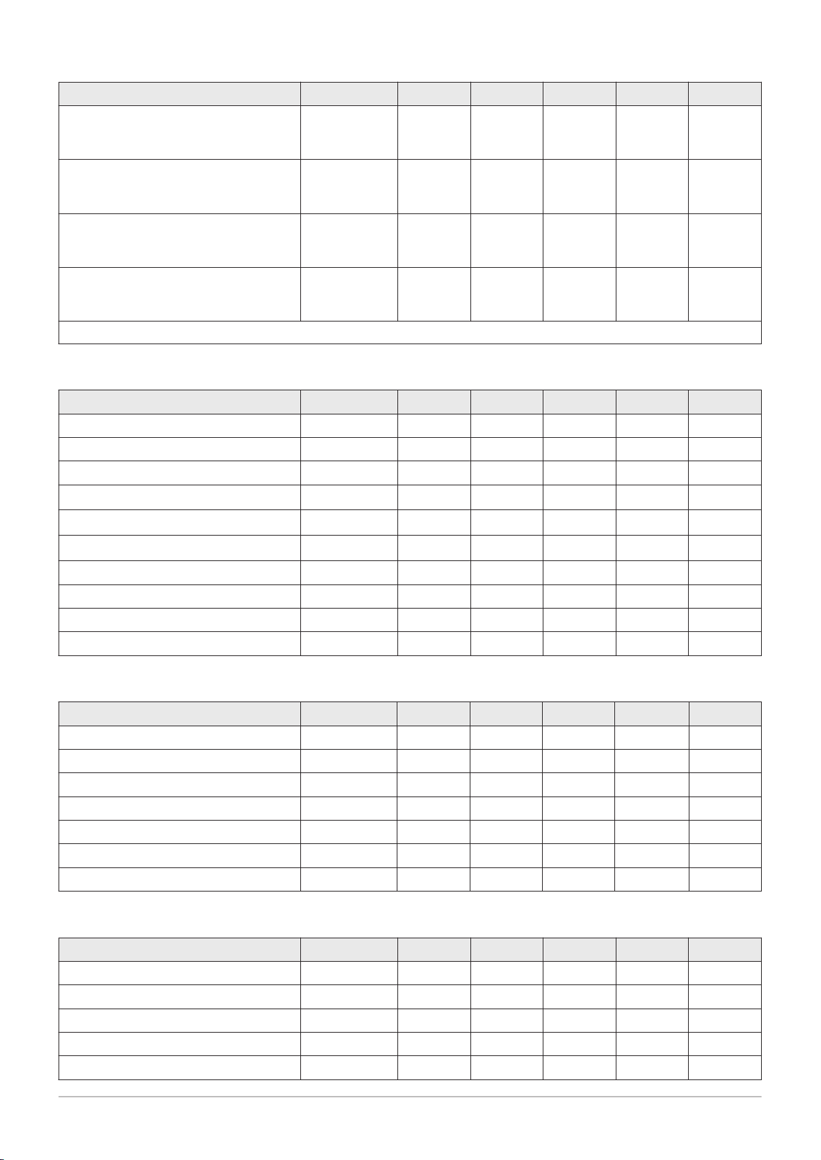
Gas 210 ECO PRO 210-80 210-120 210-160 210-200
Full load central heating efficiency (Hi)
% 97.43 97.5 97.54 97.6
80°C/60°C
(92/42 EEC)
Full load central heating efficiency (Hi)
% 104.3 104.7 105.2 105.7
50/30°C
(EN15502)
Central heating efficiency under low load
% 92.7 94.0 95.1 95.5
(Hi)
(Return temperature 60 °C)
Part load central heating efficiency (92/42
% 108.6 108.1 108.3 108.4
EEC)
(Return temperature 30 °C)
(1) Factory setting
Tab.4 Gas and flue gas data
Gas 210 ECO PRO 210-80 210-120 210-160 210-200
Gas inlet pressure G20 (H gas) min-max mbar 17 - 25 17 - 25 17 - 25 17 - 25
Gas inlet pressure G25 (L gas) min-max mbar 20 - 30 20 - 30 20 - 30 20 - 30
Gas inlet pressure G31 (propane) min-max mbar 37 - 50 37 - 50 37 - 50 37 - 50
Gas consumption G20 (H gas) min-max
m3/h
1.8 - 9.4 2.4 - 13 3.3 - 18 4.3 - 21.7
Gas consumption G25 (L gas) min-max
Gas consumption G31 (propane) min-max
m3/h
m3/h
2.1 - 11 2.8 - 15.1 3.8 - 20.9 2.1 - 25.2
1.0 - 3.6 1.0 - 4.8 1.6 - 7.0 1.8 - 8.4
NOx annual emission (BREEAM) mg/kWh - - - -
Flue gas quantity min-max kg/h 27 - 150 37 - 197 39 - 287 65 - 345
Flue gas temperature min-max °C 30 - 63 30 - 64 30 - 62 30 - 64
Maximum counter pressure Pa 130 130 130 130
Tab.5 Central heating circuit data
Gas 210 ECO PRO 210-80 210-120 210-160 210-200
Water content l 12 16 20 24
Water operating pressure min bar 0.8 0.8 0.8 0.8
Water operating pressure (PMS) max bar 6.0 6.0 6.0 6.0
Water temperature max °C 110 110 110 110
Operating temperature max °C 90 90 90 90
Water resistance (ΔT=20K) mbar 165 135 170 180
Minimum flow l/h 1120 1486 2142 2585
Tab.6 Electrical data
Gas 210 ECO PRO 210-80 210-120 210-160 210-200
Supply voltage V~ 230 230 230 230
Power consumption – full load max W 125 193 206 317
Power consumption – low load min W 36 37 53 54
Power consumption – standby min W 4 4 4 4
Electrical protection index IP 20 20 20 20
3 Technical specifications
114494 - v.05 - 06022018 15
Gas 210 ECO PRO 210-80 210-120 210-160 210-200
Fuse – main fuse (A) 6.3 AT 6.3 AT 6.3 AT 6.3 AT
Fuse – PCB (A) 1.6 AT 1.6 AT 1.6 AT 1.6 AT
Tab.7 Other data
Gas 210 ECO PRO 210-80 210-120 210-160 210-200
Total weight (empty) kg 115 135 165 188
Average acoustic level
1 metre from the boiler
(1) Maximum
(1)
at a distance of
Central heating
operation
dB(A) ≤ 59 ≤ 59 ≤ 59 ≤ 59
Tab.8 Technical parameters
Gas 210 ECO PRO 210-80 210-120 210-160 210-200
Condensing boiler Yes Yes Yes Yes
Low-temperature boiler
(1)
Yes Yes Yes Yes
B1 boiler No No No No
Cogeneration space heater No No No No
Combination heater No No No No
Rated heat output
Useful heat output at nominal heat out
put and high temperature operation
Useful heat output at 30% of rated heat
output and low temperature regime
Seasonal space heating energy efficiency
Useful efficiency at rated heat output
and high temperature regime
(2)
Useful efficiency at 30% of rated heat
output and low temperature regime
Prated
P
(2)
(1)
(1)
4
P
1
ƞ
s
ƞ
4
ƞ
1
kW 87 115 166 200
kW 87 115 166 200
kW 29.1 38.3 55.2 66.6
% - - - -
% 87.7 87.8 87.8 87.8
% 97.7 97.5 97.3 97.6
Auxiliary electricity consumption
Full load
Part load
Standby mode
elmax
elmin
P
SB
kW 0.1 0.2 0.2 0.3
kW 0.0 0.0 0.1 0.1
kW 0.004 0.004 0.004 0.004
Other items
Standby heat loss
Ignition burner power consumption
Annual energy consumption
P
stby
P
ign
Q
HE
kW - - - -
kW - - - -
kWh
- - - -
GJ
Sound power level, indoors
Emissions of nitrogen oxides NO
(1) Low temperature means 30°C for condensing boilers, 37°C for low temperature boilers and 50°C (at heater inlet) for other heating appli
ances.
(2) High temperature operation means 60 °C return temperature at heater inlet and 80 °C feed temperature at heater outlet.
L
WA
X
dB 67 67 67 67
mg/kWh 56 49 44 52
See
Refer to the back cover for contact details.
AD-0001419-01
1200
A
1272
152
316
1070 125
450
1190
305160 140140 121
61
61
3 Technical specifications
16 114494 - v.05 - 06022018
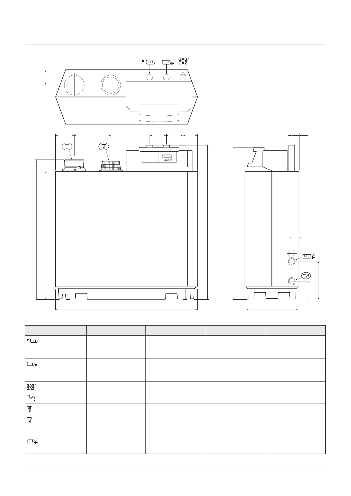
3.3 Dimensions and connections
Fig.1 Dimensions
Tab.9 Drawings
Connection 210-80 210-120 210-160 210-200
Supply
Return
Gas connection
Condensate drain
Combustion air supply
Flue gas outlet
1¼” male thread 1¼” male thread 1¼” male thread 1½” male thread
1¼” male thread 1¼” male thread 1¼” male thread 1½” male thread
1¼” male thread 1¼” male thread 1¼” male thread 1¼” male thread
Ø 32 mm external Ø 32 mm external Ø 32 mm external Ø 32 mm external
Ø150 mm Ø150 mm Ø150 mm Ø150 mm
Ø150 mm Ø150 mm Ø150 mm Ø150 mm
Height A 1309 mm 1309 mm 1309 mm 1324 mm
Second return (op
1¼” male thread 1¼” male thread 1¼” male thread 1¼” male thread
tional)
attach supplied 1¼” >
1½” adapter
attach supplied 1¼” >
1½” adapter
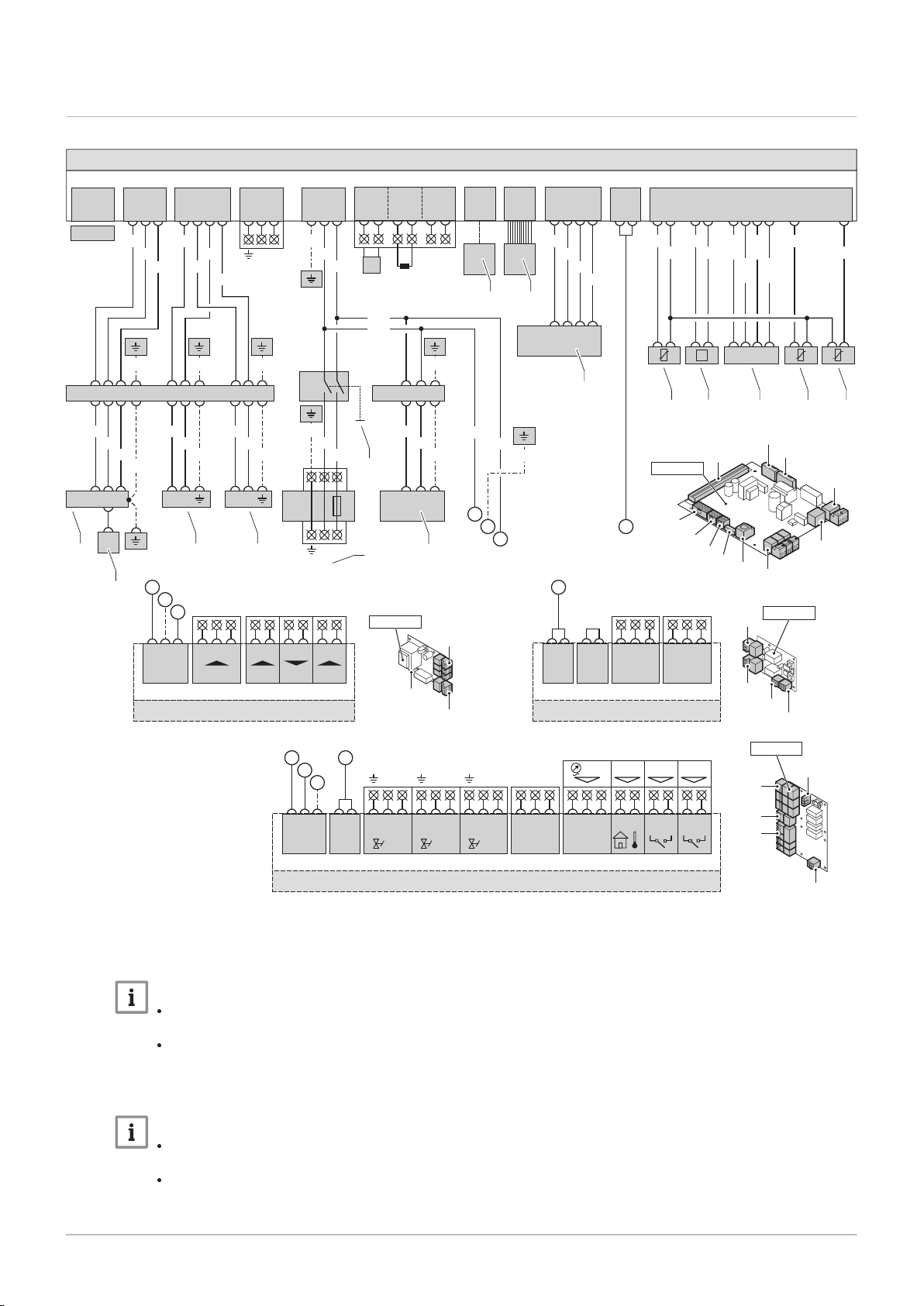
3.4 Electrical diagram
AD-3000122-01
X01
1 3
2
SCU-S01
X02
1.....6
Fgv
21
Hdv
4 5
Egv
7 83 6 9
N N NL L L
X03
Status
C NoNc
21 3
X04
O S +
21 4 5 6 73 8 9
X05
Wps Tout Gps VPs
D
A
C
B
X03
X04
X05
X02
X01
SCU-S01
X03
X04
X02a
X02
SCU-X01
SCU-X01
X02a
1.....6
X02
1.....6
Status
C NoNc
21 3
X03
Status
C NoNc
21 3
X04
D
X05
X04
X01
IF-01
IF-01
1 2
3
X01 X05
+
-
0-10V
+
-
0-10V
OTm
Nc
C
Status
No
X04
A
B
C
PCU-01
X02
X01
X03
X04
X11
X05
X10
X09
X08
X07
X06
PCU-01
X11
1 2 3 5 4 6 7 10 8 9
P
WH BK
RD BLOR
OR
YW/
WH
BR/
WH
BK/
WH
BL/
WH
X10
1.....6
D
X09
1 2 3 4
WH
BR
GN
YW
1X91 4 25
X08
1 10
X07
OT
1
On / Off
BL
3 4
RL
5 62
T
X06
BK
BL
PE-2
GN/YW
X50
6.3AT
LN
X51
X05
1 2 3
BL
BK
BL
BR
Mains
PE-2
PE-1
GN/YW
14X235 13 12
PE-7
GN/YW
1X55 32
BR
BL
GN/YW
P
230V,50Hz
BL
BK
GN/YW
A
B
C
X04
1 2
Pump
3
LN
X02
1 2 3
X03
1 2 3 4
213X21
E
BL
21 21
BR
BR
PE-6 PE-4 PE-5
PE-12
11X235 9 8 10 2 1 3 6 7 5
PE-11
GY
BL
BK
GN/YW
BL
BR
GN/YW
BL
BR
GN/YW
GN/YWGN/YWGN/YW
GY
BK
BL
BL
X01
SU-01
1
2
3 4
5
6
7 8
9
10 11 12 13 14
9
114494 - v.05 - 06022018 17
Fig.2 Electrical diagram
3 Technical specifications
1
Ignition transformer (IT)
2
Ionisation/ignition electrode (E)
3
Safety valve (SV1)
4
Important
Safety valve (SV2)
Important
For the 210-80 - 210-120, the gas valve unit
connection is 230 VAC.
For the 210-160 - 210-200, the gas valve
unit connection is 230 RAC.
For the 210-80 - 210-120 boilers, the gas
valve unit connection is 230 VAC.
For the 210-160 - 210-200 boilers, the gas
valve unit connection is 230 RAC.
5
Power supply (P)
6
On/off switch (S)
7
Computer connection (PC)
8
Control panel (HMI)
9
Fan (FAN)
10
Flow sensor (FTS)
11
Pressure switch (PS)
12
Storage parameter (PSU)
13
Return sensor (RTS)
14
Heat exchanger sensor (HTS)
BK
Black
BK/
Black/White
WH
BL
Blue
BL/
Blue/White
WH
BR
Brown

3 Technical specifications
18 114494 - v.05 - 06022018
BR/
WH
GN
GN/
YW
GY
Brown/White
Green
Green/Yellow
Grey
OR
RD
WH
YW
YW/
WH
Orange
Red
White
Yellow
Yellow/White

4 Description of the product
114494 - v.05 - 06022018 19
4.1 General description
4 Description of the product
The Gas 210 ECO PRO is a free-standing gas boiler with the following
characteristics:
High-efficiency heating.
Cast aluminium heat exchanger.
Limited emissions of polluted substances.
Has transport wheels as standard.
The following boiler types are available:
Gas 210 ECO PRO - 210-80
Gas 210 ECO PRO - 210-120
Gas 210 ECO PRO - 210-160
Gas 210 ECO PRO - 210-200
4.2
Operating principle
4.2.1
The boiler is equipped with a casing that also serves as an air box. The
fan draws in the combustion air. The gas is injected into the venturi and
mixed with the combustion air. The fan speed is controlled on the basis of
the settings, the heat demand and the prevailing temperatures measured
by the temperature sensors. The gas/air ratio control ensures an accurate
mixture of the required amounts of gas and air. This provides optimum
combustion over the entire heat input range. The gas/air mixture goes to
the burner, where it is ignited by the ignition electrode.
Gas/air regulation
4.2.2 Control
On/off control
The heat input varies between the minimum and the maximum values
on the basis of the flow temperature set on the boiler. It is possible to
connect a 2-wire on/off thermostat or a power stealing thermostat to the
boiler.
Modulating control
The heat input varies between the minimum and the maximum values
on the basis of the flow temperature determined by the modulating con
troller. The boiler output can be modulated with an appropriate modulat
ing controller.
Analogue control (0 - 10 V)
The heat input varies between the minimum and the maximum values
on the basis of the voltage present at the analogue input.
4.2.3 Circulation pump
The boiler does not have a built-in pump, but does have a built-in pump
switch. A circulating pump can be installed on the connector of the stand
ard control PCB. This can be an on/off pump or a modulating pump (with 0
- 10 V control).
The pump settings can be changed.
AD-4000038-02
1
2
3
4
5
6
7
8
9
10
11
12
13
14
15
16
17
18
19
20
21
22
23
24
25
26
28
27
2930
4 Description of the product
20 114494 - v.05 - 06022018
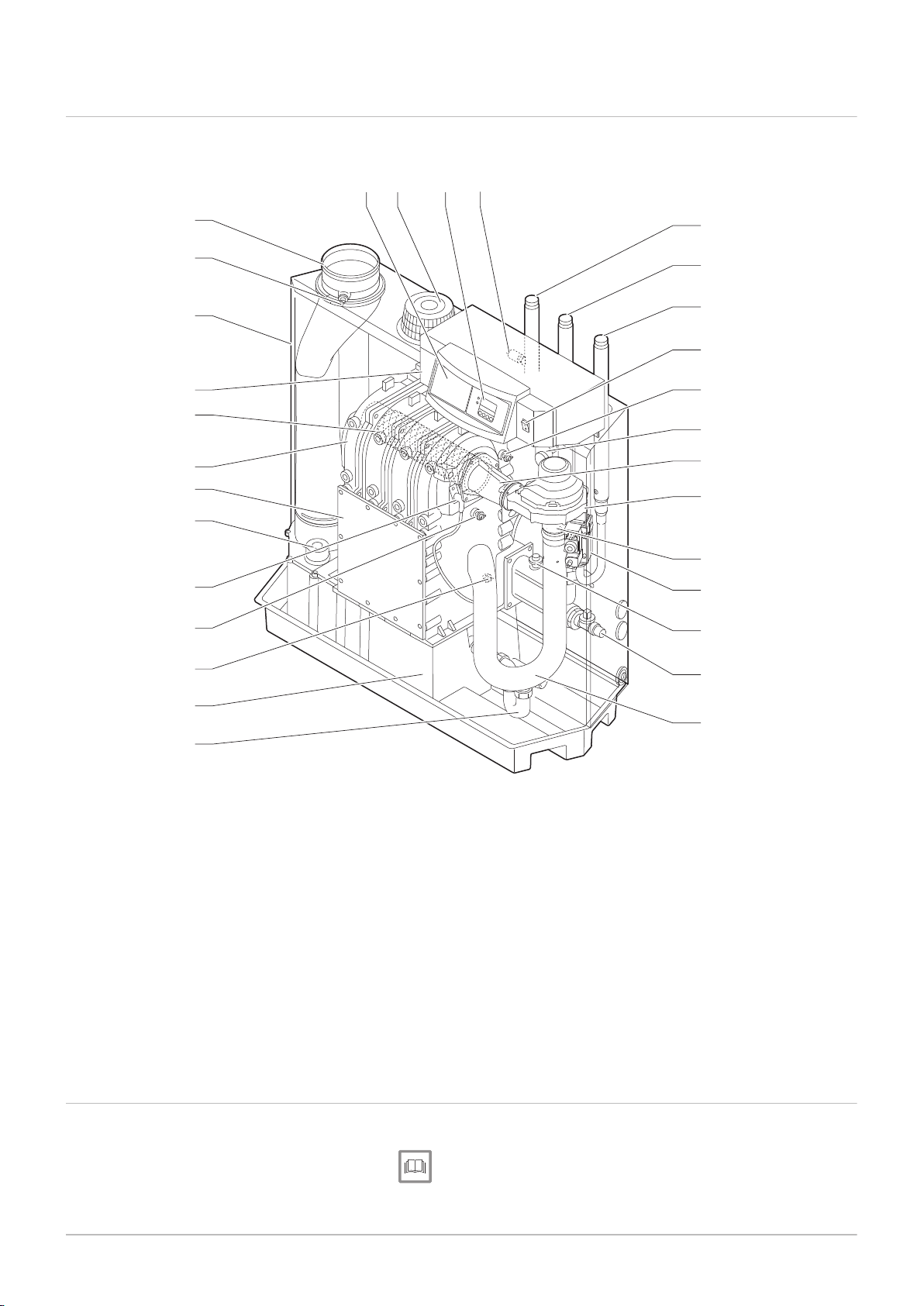
4.3 Gas 210 ECO PRO main components
Fig.3 Gas 210 ECO PRO
4.4
1
Flue gas outlet
2
O2/CO2 measurement point
3
Air box
4
Control panel
5
Burner
6
Heat exchanger
7
Inspection hatch
8
Inspection hatch for condensate collector box
9
Ignition pin
10
Boiler block sensor
11
Return temperature sensor
12
Condensate collector
13
Siphon
14
Intake silencer
15
Filling and drain valve
Control panel description
16
Hydraulic pressure sensor
17
Gas multi-block
18
Venturi
19
Fan
20
Mixing bend
21
Flue gas pressure switch
22
Flow temperature sensor
23
On/off switch
24
Gas connection
25
Return connection
26
Flow connection
27
Sensor pocket
28
display
29
Air nozzle
30
Optional built-in regulator
The Gas 210 ECO PRO boiler is supplied with a separate control panel.
See
Manual for the control panel.

4.5 Accessories and options
114494 - v.05 - 06022018 21
4 Description of the product
Various accessories can be obtained for the boiler.
Important
Contact us for more information.
AD-4000039-02
5 Before installation
22 114494 - v.05 - 06022018
5 Before installation
5.1 Installation regulations
Warning
The installer must be registered with Gas Safe and have the cor
rect ACS qualifications.
Important
Practical guidelines - see the latest version.
5.2
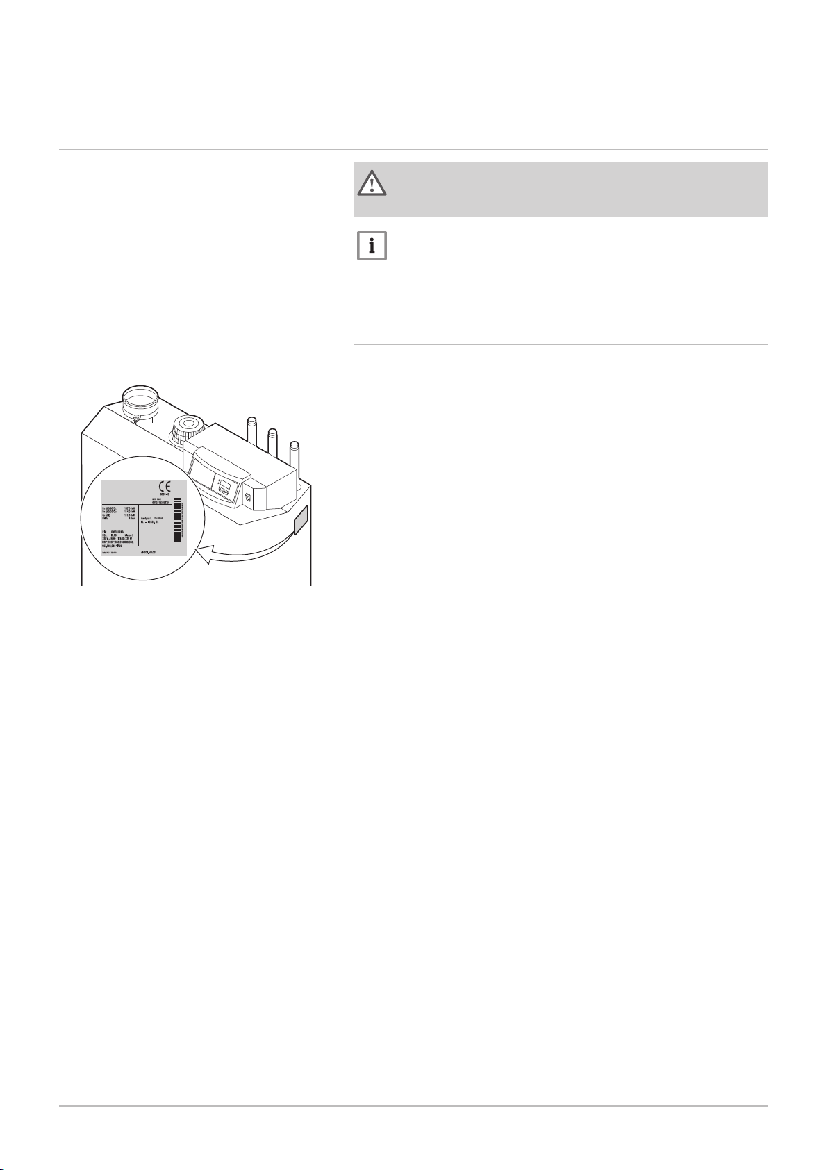
Fig.4
Choice of the location
Position of data plate
5.2.1 Data plate
The type plate is adhered above, against the casing on the right-hand
side.

Fig.5 Clearance required
AD-4000036-02
1050
450
600
1490
250119050
1690
4501190
1890
2501190450
50
1690
1190
2100
600450 450600
250 250
1050
450600
2930
250119050 2501190
114494 - v.05 - 06022018 23
5 Before installation
5.2.2 Location of the boiler
The standard inspection and maintenance operations to the boiler are car
ried out from the front. The inspection hatch on the heat exchanger is also
located here. The hydraulic connections and the flue gas outlet are located
at the front of the boiler. The control panel housing is also on the front of
the boiler.
Use the guidelines and the required installation space as a basis for de
termining the correct place to install the boiler.
When determining the correct installation space, take account of the
permitted position of the flue gas discharge and/or air supply outlet.
Ensure that there is sufficient space around the boiler for good access
and ease of maintenance.
Danger
It is forbidden to store, even temporarily, combustible products
and substances in or near the boiler.
Caution
The boiler must be installed in a frost-free area.
The boiler must have an earthed electrical connection.
A connection to the drain must be present for the condensate
drain close to the boiler.
A technical clearance of at least 600 mm is required at the front
(service side) of the boiler. However, we recommend that the
clearance is at least 1000 mm. We recommend a clearance of
at least 400 mm above the boiler. At least 50 mm on the lefthand side and 250 mm on the right-hand side.
Caution
If the power supply cable is permanently connected, you must al
ways install a main bipolar switch with an opening gap of at least 3
mm (BS EN 60335-1).

5 Before installation
24 114494 - v.05 - 06022018
5.3 Transport
5.4 Unpacking & initial preparation
The boiler comes completely assembled and is delivered in packaging on
a pallet, dimensions 700 mm x 1300 mm and 1450 mm high. Without the
packaging, the boiler will fit through all standard doorways.
Thanks to the specific compartments in the underframe, it is easy to move
the boiler using a pallet truck or forklift truck.
1. Place the pallet with the boiler in the installation room.
2. Remove the retaining straps and other pieces of packaging.
3. Lift the boiler off the pallet.
4. Slide the boiler to the correct position using the handles in the un
derframe.
5. Make sure that the boiler is horizontal.

6 Installation
AD-4000066-02
114494 - v.05 - 06022018 25
6.1 General
6 Installation
Warning
The boiler must be installed by a qualified installer in accordance
with local and national regulations.
6.2
Fig.6 Connecting the CH flow and CH re
Hydraulic connections
turn
6.2.1 Rinsing the system
The installation must be cleaned and flushed in accordance with BS 7593
(2006) and BSRIA BG 33/2014.
Before a new boiler can be connected to an existing or new system, the
entire system must be thoroughly cleaned and flushed. This step is abso
lutely crucial. The flushing helps to remove residue from the installation
process (weld slag, fixing products etc.) and accumulations of dirt (silt,
mud etc.)
Important
Flush the system with a volume of water equivalent to at least
three times the volume of the system. Flush the DHW pipes with a
volume of water equivalent to at least 20 times the volume of the
pipes.
Important
Due to the presence of an aluminium heat exchanger, suitable
chemicals and the correct use of these chemicals should be dis
cussed with specialist water treatment companies.
6.2.2 Connecting the heating circuit
1. Remove the dust cap on the CH flow connection terminal.
2. Remove the dust cap on the central heating return connection.
3. Attach the outlet pipe for central heating water to the central heating
flow.
4. Attach the inlet pipe for central heating water to the central heating
return.
5. Connect a safety valve to the boiler's flow connection.
6. Connect the pump to the boiler's return connection.
Always connect the boiler in a way that will guarantee the water flow
through the unit during operation. When the boiler is used in a system with
two return pipes, the return pipe must be used as a cold return. The sec
ond return pipe is then used as a hot return. Contact us for more informa
tion.

AD-4000068-01
AD-4000067-02
GAS /
GAZ
6 Installation
26 114494 - v.05 - 06022018
Caution
If using plastic pipes, follow the manufacturer's (connection) in
structions.
6.2.3 Connecting the condensate discharge pipe
Fig.7 Connecting the condensate drain
6.3
Gas connection
Fig.8 Connecting the gas pipe
1. Fit a plastic drain pipe of Ø 32 mm or larger to the condensate
drain, terminating in the drain.
Caution
Use only plastic material for the discharge pipe due to the acidi
ty (pH 2 to 5) of the condensate.
Do not make a fixed connection in order to prevent an overpres
sure in the siphon.
Never seal the condensate drain.
Condensed water must not be discharged into a gutter.
The drain pipe must slope down at least 5 - 10 mm per metre,
the maximum horizontal length is 5 metres.
1. Before starting work on the gas pipes, turn off the main gas tap.
2. Before installing, check that the gas meter has sufficient capacity.
Take into account the consumption of all appliances.
3. Notify the local energy company if the gas meter has insufficient ca
pacity.
4. Remove the dust cap on the gas connection .
5. Fit the gas supply pipe.
6. Also fit a gas isolation valve in this pipe, near the boiler.
Caution
Remove dirt and dust from the gas pipe.
Always perform welding work at a sufficient distance from the
boiler.
Important
We recommend installing a gas filter to prevent clogging of the
gas valve unit.

6.4 Air supply/flue gas connections
AD-3001055-01
AD-3001056-01
AD-3001057-01
AD-3001058-02
114494 - v.05 - 06022018 27
Tab.10 Types of flue gas connections
Type Principle Description
6.4.1 Classification
Important
The installer is responsible ensuring that the right type of flue
gas outlet system is used and that the diameter and length are
correct.
Always use connection materials and roof terminal supplied by
the same manufacturer. Consult the manufacturer for compati
bility details.
6 Installation
Permitted manufacturers
(1)
B
23P
Room-ventilated version
Without down-draught diverter.
Flue gas discharge via the roof.
Air from the installation area.
Connection material and roof
terminal:
Cox Geelen
Muelink & Grol
Skoberne
C
13
Room-sealed version
Discharge in the outside wall.
Inlet opening for the air supply is in the same
pressure zone as the discharge (e.g. a com
bined outside wall feed-through).
Parallel not permitted
Outside wall terminal and con
nection material:
Remeha, combined with con
nection material from Muelink
& Grol
Cox Geelen
Muelink & Grol
C
33
Room-sealed version
Flue gas discharge via the roof.
Inlet opening for the air supply is in the same
pressure zone as the discharge (e.g. a concen
tric roof feed-through).
Roof terminal and connection
material
Remeha, combined with con
nection material from Muelink
& Grol
Cox Geelen
Muelink & Grol
Skoberne
C
53
Connection in different pressure zones
Closed unit.
Separate air supply duct.
Separate flue gas discharge duct.
Discharging into various pressure areas.
Connection material and roof
terminal:
Cox Geelen
Muelink & Grol
Skoberne
The air supply and the flue gas outlet must not
be placed on opposite walls.

AD-3001059-01
6 Installation
28 114494 - v.05 - 06022018
Type Principle Description
C
63
This type of unit is supplied by the manufacturer
without a supply and discharge system.
C
93
(2)
Room-sealed version
Air supply and flue gas discharge duct in shaft
or ducted:
Concentric.
Air supply from existing duct.
Flue gas discharge via the roof.
Inlet opening for the air supply is in the same
pressure zone as the discharge.
Permitted manufacturers
(1)
When selecting the material,
please note the following:
Condensed water must flow
back to the appliance
The material must be resist
ant to the flue gas tempera
ture of this appliance.
Maximum permissible recir
culation of 10%.
The air supply and the flue
gas outlet must not be placed
on opposite walls.
Minimum permitted pressure
difference between the air
supply and the flue gas outlet
is -200 Pa (including -100 Pa
wind pressure).
Connection material and roof
terminal:
Cox Geelen
Muelink & Grol
Skoberne
(1) The material must also satisfy the material property requirements from the relevant chapter.
(2) See table for shaft or duct requirements
For more information, see
Material, page 29
6.4.2 Requirements for shaft for C
93
Tab.11 Minimum dimensions of shaft or duct
Version (D) Without air supply With air supply
Ø duct □ duct Ø duct □ duct
Rigid 150 mm 200 mm 200 x 200 mm 220 mm 220 x 220 mm
Concentric 150/200 mm 270 mm 270 x 270 mm - -

AD-3000330-02
□
D
Ø
D
AD-3001120-01
EN 14471 - T120 P1 W 1 O50 LI E U0
EN 1856-1 - T120 P1 W VxL40045 G(xx)
1
3
2
4
5
6 Installation
114494 - v.05 - 06022018 29
Fig.9 Minimum dimensions of shaft or
duct
Fig.10 Sample string
Important
The shaft must comply with the air density requirements of the lo
cal regulations.
Important
Always clean shafts thoroughly when using lining pipes and/or
an air supply connection.
It must be possible to inspect the lining duct.
6.4.3 Material
Use the string on the flue gas outlet material to check whether it is suitable
for use on this appliance.
1
EN 14471 of EN 1856–1: The material is CE approved according to
this standard. For plastic this is EN 14471, For aluminium and
stainless steel this is EN 1856-1.
2
T120: The material has temperature class T120. A higher number
is also allowed, but not lower.
3
P1: The material falls into pressure class P1. H1 is also allowed.
4
W: The material is suitable for draining condensation water
(W=’wet’). D is not allowed (D=’dry’).
5
E: The material falls into fire resistance class E. Class A to D are
also allowed, F is not allowed. Only applicable to plastic.
Warning
The coupling and connection methods may vary depending on
the manufacturer. It is not permitted to combine pipes, coupling
and connection methods from different manufacturers. This also
applies to roof feed-throughs and common channels.
The materials used must comply with the prevailing regulations
and standards.
Please contact us to discuss using flexible flue gas outlet mate
rial.
Tab.12 Overview of material properties
Version Flue gas outlet Air supply
Material Material properties Material Material properties
Single-wall, rigid
(1)
Plastic
Stainless steel
Thick-walled,
aluminium
(2)
With CE marking
(2)
Temperature class T120 or
higher
Condensate class W (wet)
Pressure class P1 or H1
Fire resistance class E or bet
(3)
ter
(1) according to EN 14471
(2) according to EN 1856
(3) according to EN 13501-1
Plastic
Stainless steel
Aluminium
With CE marking
Pressure class P1 or H1
Fire resistance class E or bet
(3)
ter

AD-3001094-01
ød
1
AD-3000963-01
ød
1
øD
1
6 Installation
30 114494 - v.05 - 06022018
6.4.4 Dimensions of flue gas outlet pipe
Warning
The pipes connected to the flue gas adapter must satisfy the fol
lowing dimension requirements.
Fig.11
Dimensions of open connection
Fig.12 Dimensions of parallel connection
d
External dimensions of flue gas outlet pipe
1
Tab.13 Dimensions of pipe
d1 (min-max)
150 mm 149 - 151 mm
d
External dimensions of flue gas outlet pipe
1
D
External dimensions of air supply pipe
1
Tab.14 Dimensions of pipe
d1 (min-max) D1 (min-max)
150/150 mm 149 - 151 mm 149 - 151 mm
6.4.5 Length of the air and flue gas pipes
The maximum length of the flue gas outlet and air supply channel vary de
pending on the appliance type; consult the relevant chapter for the correct
lengths.
Important
When using bends, the maximum chimney length (L) must be
shortened according to the reduction table.
For adaptation to another diameter use approved transitions
The boiler is also suitable for longer chimney lengths and diam
eters other than those specified in the tables. Contact us for
more information.
Room-ventilated model (B
23P
)
In an open design, the air input remains open; only the flue gas outlet will
be connected. The boiler receives the necessary combustion air direct
from the installation room.

AD-4000099-01
L =
6 Installation
114494 - v.05 - 06022018 31
Caution
The air supply opening must stay open.
The installation area must be equipped with the necessary air
supply openings. These openings must not be obstructed or
shut off.
If the boiler, in room-ventilated operation, has been set up in a
(very) dusty room, use the air supply filter (accessory).
Use of the air inlet filter is compulsory when the boiler is ex
posed to building dust.
Fig.13
Room-ventilated version
L Length of the flue gas outlet channel to roof feed-through
Flue gas outlet
Tab.15 Maximum length for open design
Maximum length L
(1)
Pipeline diameter 100 mm 110 mm 130 mm 150 mm
Gas 210 ECO PRO 210-80 19 m 35 m
Gas 210 ECO PRO 210-120 20 m 48 m
50 m
(2)
50 m
50 m
Gas 210 ECO PRO 210-160 8 m 22 m 45 m
Gas 210 ECO PRO 210-200 14 m 31 m
(1) Calculated with rigid tube and discharge without cover ( "free" opening)
(2) With retention of the maximum flue length it is possible to apply an extra 5 times 90º or 10 times 45º elbows.
50 m
50 m
50 m
50 m
(2)
(2)
(2)
(2)
(2)
180 mm
(2)
(2)
Room-sealed model (C13, C33, C63, C93)
With a room-sealed version, both the flue gas outlet and the air supply
openings are connected (in parallel).

AD-4000100-01
L = +
AD-4000101-01
L = +
6 Installation
32 114494 - v.05 - 06022018
Fig.14 Room-sealed version
L Combined length of the flue gas outlet and air supply channel to
the roof feed-through
Flue gas outlet
Tab.16 Maximum chimney length for room-sealed operation
Maximum length L
(1)
Pipeline diameter 100 mm 130 mm 130 mm 150 mm 180 mm
Diameter of concentric roof terminal 100 mm 130 mm 150 mm 150 mm 150 mm
Gas 210 ECO PRO 210-80 14 m 50 m 60 m
60 m
(2)
60 m
(2)
Gas 210 ECO PRO 210-120 4 m 38 m 44 m 60 m 60 m
Gas 210 ECO PRO 210-160 15 m 22 m 44 m 60 m
Gas 210 ECO PRO 210-200 6 m 8 m 24 m 60 m
(1) Calculated with rigid tube and discharge without cover ( "free" opening)
Connection in different pressure areas (C53)
The supply of combustion air and discharge of flue gas is possible in dif
ferent areas of pressure.
Important
The maximum permitted height difference between the combus
tion air supply and the flue gas outlet is 36 m.
Fig.15 Different pressure zones
L Total length of the flue gas outlet and air supply duct
Flue gas outlet
Tab.17 Maximum chimney length in the various pressure zones
Maximum length L
Pipeline diameter 150 mm
Gas 210 ECO PRO 210-80
60 m
(1)
Gas 210 ECO PRO 210-120 60 m
Gas 210 ECO PRO 210-160 32 m
Gas 210 ECO PRO 210-200 19 m
(1) With retention of the maximum flue length it is possible to apply an extra 5
times 90º or 10 times 45º elbows.

6 Installation
114494 - v.05 - 06022018 33
Reduction table
Tab.18 Pipe reduction for each element used
Diameter
100 mm 1.4 4.9
110 mm 1.5 5.4
130 mm 1.0 1.8
150 mm 1.2 2.1
180 mm 1.4 2.5
Pipe reduction (in metres)
45° bend 90° bend
6.4.6 Additional guidelines
Installation
For installing the flue gas outlet and air supply materials, refer to the in
structions of the manufacturer of the relevant material. After installation,
check at least all flue gas outlet and air supply parts for tightness.
Warning
If the flue gas outlet and air supply materials are not installed in
accordance with the instructions (e.g. not leak-proof, not correctly
bracketed), this can result in dangerous situations and/or physical
injury.
Make sure that the flue gas outlet pipe towards the boiler has a sufficient
gradient (at least 50 mm per metre) and that there is a sufficient conden
sate collector and discharge (at least 1 m before the outlet of the boiler).
The bends used must be larger than 90° to guarantee the gradient and a
good seal on the lip rings.
Condensation
Direct connection of the flue gas outlet to structural ducts is not permit
ted because of condensation.
If condensate from a plastic or stainless steel pipe section can flow back
to an aluminium part in the flue gas outlet, this condensate must be dis
charged via a collector before it reaches the aluminium.
Important
Contact us for more information.
6.4.7 Air/flue gas adapter
The boilers can be used in room-ventilated or room-sealed operation. The
air supply terminal set must be used for a closed arrangement (available
as an accessory).
6.4.8 Connecting the flue gas outlet
Proceed as follows to connect the flue gas outlet:
1. Remove the cap from the flue gas outlet opening.
2. Fit the flue gas outlet pipe to the boiler.
3. Fit the subsequent flue gas outlet pipes in accordance with the man
ufacturer's instructions.

6 Installation
34 114494 - v.05 - 06022018
Caution
The pipes must be flue gas-tight and corrosion-resistant.
The materials used must comply with the prevailing regulations
and standards.
The flue gas outlet pipe must be smooth and deburred.
Connect the pipes so that they are stress-free.
The pipes must not rest on the boiler or flue gas adapter.
Fit the horizontal parts sloping down towards the boiler, with a
slope of 50 mm per metre.
Maximum bracket spacing for vertical pipes is 2 m.
Maximum tilt of vertical pipes is 20 mm per meter.
Use a bracket at each connection for horizontal pipes.
6.4.9 Connecting the air supply
1. Remove the dirt trap filter from the air supply opening
2. Fit the air supply connection kit (accessory).
3. Fit the air supply pipe to the boiler.
4. Fit the air supply pipes seamlessly together.
5. Fit the subsequent air supply pipes in accordance with the manufac
turer's instructions.
Caution
The pipes must be airtight and waterproof.
The air supply pipe must be smooth and deburred.
Connect the pipes so that they are stress-free.
Maximum bracket spacing for vertical pipes is 2 m.
Maximum tilt of vertical pipes is 20 mm per meter.
The pipes must not be resting on the boiler or air supply adapt
er.
Fit the horizontal parts sloping down towards the air supply out
let, (with a slope of 50 mm per metre).
Use a bracket at each connection for horizontal pipes.
6.5
Electrical connections
6.5.1 Recommendations
Warning
Electrical connections must always be made with the power
supply disconnected and only by qualified installers.
The boiler is completely pre-wired. Never change the internal
connections of the control panel.
Make sure you establish an earth connection before connecting
the electricity.
Establish the electrical connections in accordance with:
The instructions of the current standards.
The instructions of the wiring diagrams supplied with the boiler.
The recommendations in this manual.
Separate the sensor cables from the 230 V cables.
6.5.2 Control unit
Connection voltage 230 V / 50 Hz
Safety delay 3.5 seconds.
Anti-tripping time Can be adapted by 1-10 minutes.
Pump finishing time Adjustable from 0 to 98 minutes or continuous
ly (= 99 minutes), standard setting is 3 mi
nutes.

AD-0001420-01
1
4x
2
PCU-01
SU
6 Installation
114494 - v.05 - 06022018 35
Fig.16 Standard control PCB (PCU-01)
with security PCB (SU)
Maximum recorded
300 VA.
power of external pump
Recorded power in: Standby Part load Full load
210-80 4 W 36 W 125 W
210-120 4 W 37 W 193 W
210-160 4 W 53 W 206 W
210-200 4 W 54 W 317 W
6.5.3 Accessing the terminal connectors and control PCBs
The control panel casing contains the standard control PCBPCU-01, the
security PCB SU and the optional PCB(s) for the external terminals.
Accessing the control PCB and terminal connectors::
1. Unscrew the four screws on the casing cover.
2. Remove the cover

AD-4100111-01
X1
X7
X8
X9X11 X10
X2
X3
X5
F1 1.6 AT
Statuson/of
N
N L
Pump
L
OT BL RL
OT BL RL
X6
X4
PCU-01
N L
Pump
AD-4000044
Statuson/of
N
N L
Pump
L
OT BL RL
OT BL RL
X6 X5
X4
N L
Pump
AD-4000044
Statuson/of
N
N L
Pump
L
OT BL RL
OT BL RL
X6 X5
X4
N L
Pump
AD-4000043
Statuson/of
N
N L
Pump
L
OT BL RL
OT BL RL
X6 X5
X4
N L
Pump
6 Installation
36 114494 - v.05 - 06022018
6.5.4 Connection options for the standard control PCB (PCU-01)
Fig.17 Standard control PCB (PCU-01)
Fig.18 Connecting the on/off thermostat
Various thermostats and regulators can be connected to the standard con
trol PCB (PCU-01), as well as the circulation pump or a PC.
On/off regulator (OT)
The boiler is suitable for connecting an on/off regulator.
1. Connect the regulator to the On/off - OT terminals on the terminal
block X6 (it doesn’t matter which wire is connected to which wiring
terminal).
Fig.19 Connecting the modulating regula
tor
Fig.20 Blocking input
Connecting the modulating regulator
The boiler is ready to communicate via the OpenTherm protocol. Modulat
ing regulators can be connected in accordance with the OpenTherm proto
col. The connection is created using a two-wire cable on the On/off - OT
terminals on the terminal block X6 (it doesn’t matter what wire is connec
ted in what wiring terminal).
Blocking input
The boiler has a blocking input. If this contact is opened, the boiler will be
blocked or locked out. This input can be found on the BL terminals on the
terminal block X6.
Important
First remove the bridge if this input is used.
A parameter setting can be used to change the function of the input.
See
Manual for the control panel.

Release input
AD-4000042
Statuson/of
N
N L
Pump
L
OT BL RL
OT BL RL
X6 X5
X4
N L
Pump
AD-4000045
Statuson/of
N
N L
Pump
L
OT BL RL
OT BL RL
X6 X5
X4
N L
Pump
AD-0001421-01
on/of
L
OT BL RL
OT BL RL
X11
X10
X9
X6
X7
X8
X9X11 X10
AD-0000054-01
Status 0-10 0-10
Nc NoC
Nc No OTm 0 + 0 +C
OTm 0 + 0 +
X5
X4
X1
IF-01
%
1
2
114494 - v.05 - 06022018 37
6 Installation
Fig.21
Release input
Fig.22 Connecting the circulation pump
The boiler also comes with a release input that can be used to release/
block the burner. This input can be used in conjunction with flue gas valve
end switches, hydraulic shut-off valves etc., for example. This input can be
found on the RL terminals on the terminal block X6.
Connecting the circulation pump
A pump with the following specifications can be connected:
On/off pump with a supply voltage of 230 VAC (50Hz) and 300 VA.
Attach the pump to the Pump terminals on the terminal block X4. By se
lecting a programme at user level, the finishing time for the circulation
pump can be set to when heat demand has ended.
Connecting a PC
Fig.23 Connecting a PC
Fig.24 IF-01 PCB
A PC can be connected to the ‘telephone connector’ X7 using a serial/
optional serial cable and the corresponding interface. Together with the
Recom software, you can import, alter and export various boiler settings.
See the user instructions that come with this software.
6.5.5 Connection options for the 0–10 V PCB (IF-01)
The IF-01 PCB can be built into the instrument box or the housing for the
PCBs. See the instructions provided with the product.

AD-0000055-01
1
2
%
2 2
6 Installation
38 114494 - v.05 - 06022018
Caution
Do not connect a frost thermostat or room thermostat to the boiler
if using the 0–10 V PCB.
Connecting the status relay (Nc)
If the boiler locks out, a relay is de-energised and the alarm can be trans
mitted via a potential-free contact (maximum 230 V, 1 A) on terminals Nc
and C of the connector.
Connection (OTm)
The interface uses OpenTherm to communicate with the boiler control
unit. To make this possible, the OTm connection must be connected to the
OpenTherm input of the boiler control unit.OTm
Analogue input (0-10 V)
A choice can be made with this control between control based on temper
ature or heat output. The two controls are described briefly below.
1. Connect the input signal to terminals 0–10 of the connector.
Tab.19 Temperature-based control (°C)
Jumper 2 Input signal (V) Temperature °C Description
Fig.25 Switch jumper (2)
0–1.5 0–15 Boiler off
1.5–1.8 15–18 Hysteresis
1.8–10 18–100 Desired temperature
The 0–10 V signal controls the boiler supply temperature. This control
modulates on the basis of flow temperature. The output varies between
the minimum and maximum value on the basis of the flow temperature set
point calculated by the controller.
A jumper (2) on the interface is used to select either temperature-based
control (
) or output-based control (%).
Tab.20 Control based on heat output
Jumper 2 Input signal (V) Heat output (%) Description
(1)
0–2.0
%
2.0–2.2
2.0–10
(1) Dependent on the minimum modulation depth (set speeds, standard 20%)
(1)
(1)
0–20 Boiler off
20–22 Hysteresis
20–100 Desired heat output
The 0–10 V signal controls the boiler output. This control modulates on the
basis of the heat output. The minimum output is linked to the boiler's mod
ulation depth. The output varies between the minimum and maximum val
ue on the basis of the value defined by the controller.

Analogue output (0–10 V)
AD-0000056-01
1
2
%
1 1
AD-0000059-01
SCU-X01
X2
X2a
X4
Status
CNc No
CNcNo
X3
Status
CNc No
CNcNo
SW2SW1
114494 - v.05 - 06022018 39
6 Installation
Fig.26
Switch jumper (1)
This feedback can be based on temperature or heat output. The two con
trols are described briefly below.
A jumper (1) on the interface is used to select either temperature ( ) or out
put (%).
Tab.21 Temperature message
Jumper 1 Output signal (V) Temperature °C Description
0.5 – Alarm
1–10 10–100 Supplied tempera
ture
Tab.22 Output message
Jumper 2 Output signal (V) Heat output (%) Description
0 0–15 Boiler off
0.5 15–20 Alarm
%
(1)
2.0–10
(1) Dependent on the minimum modulation depth (set speeds, standard 20%)
6.5.6
Connection options for the PCB (SCU-X01)
20–100 Supplied heat output
Fig.27 -X01 PCB
The -X01 PCB has two potential-free contacts (status), which can be con
figured as required. Depending on the setting, a maximum of two messag
es about the status of the boiler can be transmitted. See table. Select the
messages required using rotary knobs SW1 and SW2. Use rotary knob
SW1 for messages on the status connector X3. Use rotary knob SW2 for
messages on the status connector X4.
Tab.23 Configuring the rotary knobs
Position C-NO C-NC
0 Alarm standby Alarm active
1 Alarm inverted active Alarm inverted standby
2 Burning standby Burning active
3 Burning inverted active Burning inverted standby
4 Burning low standby Burning low active
5 Burning high standby Burning high active
6 Maintenance message standbyMaintenance message active
7 CH mode standby CH mode active
8 DHW mode standby DHW mode active
9 CH pump standby CH pump active
6.6
Filling the installation
6.6.1 Water treatment and water quality
In many cases, the boiler and central heating system can be filled with
normal tap water and water treatment will not be necessary.

6 Installation
40 114494 - v.05 - 06022018
The quality of the CH water must comply with certain limit values, which
can be found in the Water quality instructions. The regulations and guide
lines in this manual must be observed at all times.
6.6.2 Filling the siphon
1. Fill the siphon with clean water.
Danger
The siphon must always be sufficiently filled with water. This pre
vents flue gases from entering the room.
6.6.3 Filling the installation
1. Disconnect the boiler from the power supply.
2. Fill the central heating system with clean tap water.
Important
The recommended water pressure is between 1.5 bar and 2 bar.
3. Check the water-side connections for tightness.
4. Power up the boiler.
Important
Top up the central heating system by at least 0.8 bar if the water
pressure drops too low.

7 Commissioning
114494 - v.05 - 06022018 41
7.1 Checklist before commissioning
7 Commissioning
7.1.1 Preparing the boiler for commissioning
Procedure to prepare the boiler for commissioning
1. Check the gas circuit.
2. Check the hydraulic circuit.
3. Check the water pressure in the central heating system.
4. Check the electrical connections of the thermostat and the other ex
ternal connections.
5. Check the other connections.
6. Test the boiler at full load. Check the setting of the gas/air ratio.
7. Test the boiler at part load. Check the setting of the gas/air ratio.
8. Final activities.
7.1.2 Gas circuit
Warning
Ensure that the boiler is disconnected from the power supply.
7.2
1. Open the main gas tap.
2. Open the boiler gas tap.
3. Check the gas inlet pressure at the measuring point on the gas pipe.
4. Vent the gas supply pipe by unscrewing the measuring point.
5. Tighten the measuring point again when the pipe has been fully ven
ted.
6. Check all connections for gas tightness. The maximum allowable
test pressure is 60 mbar.
7.1.3 Hydraulic circuit
1. Check the water pressure in the central heating system.
If necessary, top up the central heating system.
2. Check the siphon; it should be fully filled with clean water.
3. Check the water-side connections for tightness.
7.1.4 Connections for the air and flue gas pipes
1. Check the flue gas outlet and air supply connections for tightness.
7.1.5 Electrical connections
1. Check the electrical connections.
Commissioning procedure
Warning
Initial commissioning must be done by a qualified professional.
1. Open the main gas tap.
2. Open the boiler gas tap.
3. Switch the power on with the boiler's on/off switch.
4. Set the components (thermostats, control) so that heat is deman
ded.
The start-up program will start and cannot be interrupted. During
the start-up cycle, all segments of the display are shown briefly.
Error during start-up procedure:
In the event of a fault, a message with the corresponding code is dis
played.

AD-3000112-01
X
.
X
X
7 Commissioning
42 114494 - v.05 - 06022018
The meaning of the error codes can be found in the error table.
7.3 Gas settings
7.3.1 Adaptation to a different gas type
Warning
Only a qualified installer may carry out the following operations.
Tab.24 Factory setting G20 (H gas)
Parameter Description 210-80 210-120 210-160 210-200
Maximum speed for central heating 51 64 48 57
Minimum speed for central heating 12 13 10 12
Start speed 17 17 17 17
Restrictor ø (mm) 8,4 8,4 – –
Before operating with a different type of gas, carry out the following steps.
Fig.28 Replacing restrictor
1. Check the correct diameter of the existing restrictor (see table) and
replace it if necessary.
2. Set the fan speed as indicated in the table for the relevant gas type.
The speed can be changed with a parameter setting.
Tab.25 Adjustment for gas type G31 (propane)
Parameter Description 210-80 210-120 210-160 210-200
Maximum speed for central heating 52 61 60 55
Minimum speed for central heating 15 14 15 13
Start speed 20 20 22 22
Restrictor ø (mm) 6,5 6,5 10 10
3. Check the setting of the gas/air ratio.
7.3.2 Checking/setting the combustion
1. Unscrew the cap from the flue gas measuring point.
2. Insert the probe for the flue gas analyser into the measurement
opening.
Warning
During measurement, seal the opening around the sensor fully.
Important
The flue gas analyser must have a minimum accuracy of
±0.25% O2/CO2.
The flue gas analyser must meet the requirements of BS 7927
or BS-EN 503793 and be calibrated according to the manufac
turer's requirements.
3. Measure the percentage of O2/CO2 in the flue gases. Take meas
urements at full load and at part load.

Fig.29 Setting full load
AD-4000053-01
1x
AD-3000113-01
114494 - v.05 - 06022018 43
7 Commissioning
Setting full load
1. Press the key.
The symbol will appear in the display.
2. Wait a while until appears in the display.
Full load has now been set.
Checking/setting values O2/CO2 at full load
1. Set the boiler to full load.
2. Measure the percentage of O2/CO2 in the flue gases.
3. Compare the measured value with the checking values in the table.
Tab.26 Checking/setting values for O2 at full load for G20
Values at full load for
O2 %
(1)
G20
210-80 3,9 - 5,2
210-120 3,9 - 5,2
210-160 4,3 - 5,2
210-200 4,3 - 5,2
(1) Nominal value
(1)
- 6,5 8,1 - 8,8
(1)
- 6,5 8,1 - 8,8
(1)
(1)
CO2 %
(1)
8,8
- 9,3
(1)
8,8
- 9,3
(1)
(1)
(1)
- 9,5
- 9,5
Fig.30 210-160 - 210-200
Tab.27 Checking/setting values for O2 at full load for G31
Values at full load for
O2 %
(1)
CO2 %
(1)
G31
210-80 4,7 - 5,7
210-120 4,7 - 5,7
210-160 4,9 - 5,7
210-200 4,9 - 5,7
(1) Nominal value
(1)
- 6,7 9,3 - 10,0
(1)
- 6,7 9,3 - 10,0
(1)
(1)
10,0
10,0
(1)
- 10,5
(1)
- 10,5
(1)
- 10,7
(1)
- 10,7
4. If the measured value is outside of the values given in the table, cor
rect the gas/air ratio.
Important
The 210-80 and 210-120 boilers are equipped with a restrictor on
the gas valve unit. They can therefore only be set to part load.
5. Using the adjusting screw, set the percentage of O2/CO2 for the gas
type being used to the nominal value. This should always be inside
the highest and lowest setting limit. The direction in which the ad
justment screw must be turned to increase or decrease the gas flow
is indicated on the gas valve unit.
6. Check the flame through the inspection window.
Important
The flame must not blow off.

AD-4000054-01
1x
7 Commissioning
44 114494 - v.05 - 06022018
Fig.31 Setting low load
Setting low load
1. Press the key.
The symbol will appear in the display.
2. Wait a while until appears in the display.
3. Press the key until appears on the display.
Low load has now been set.
Checking/setting values for O2/CO2 at part load
1. Set the boiler to part load.
2. Measure the percentage of O2/CO2 in the flue gases.
3. Compare the measured value with the checking values in the table.
Tab.28 Checking/setting values for O2 at part load for G20
Values at part load
O2 %
(1)
for G20
210-80 3,4 - 4,3
210-120 3,4 - 4,3
210-160 3,4 - 4,3
210-200 3,4 - 4,3
(1) nominal value
(1)
(1)
(1)
(1)
CO2 %
(1)
9,3
- 9,8
(1)
9,3
- 9,8
(1)
9,3
- 9,8
(1)
9,3
- 9,8
(1)
Tab.29 Checking/setting values for O2 at part load for G31
Values at part load
O2 %
(1)
CO2 %
(1)
for G31
210-80 4,1 - 4,9
210-120 4,1 - 4,9
210-160 4,1 - 4,9
210-200 4,1 - 4,9
(1) nominal value
(1)
(1)
(1)
(1)
10,5
10,5
10,5
10,5
(1)
- 11,0
(1)
- 11,0
(1)
- 11,0
(1)
- 11,0
4. If the measured value is outside of the values given in the table, cor
rect the gas/air ratio.

AD-3000111-01
AD-3001124-01
Adjusted for / Réglée pour /
Ingesteld op / Eingestellt auf
/ Regolato per / Ajustado
para / Ρυθμισμένο για /
Nastawiony na / настроен
для / Reglat pentru /
настроен за / ayarlanmıştır /
Nastavljen za / beállítva/
Nastaveno pro / Asetettu
kaasulle / Justert for/
indstillet til/ ضبط ل :
C
(10)3(X)
Gas
C
(12)3(X)
mbar
Parameters / Paramètres /
Parameter / Parametri /
Parámetros / Παράμετροι /
Parametry / Параметры /
Parametrii / Параметри /
Parametreler / Paraméterek
/ Parametrit / Parametere /
Parametre / المعلمات :
G20
20
DP003 - 3300
GP007 - 3300
GP008 - 2150
GP009 -
7 Commissioning
114494 - v.05 - 06022018 45
Fig.32 Adjusting screw
7.4
Final instructions
Fig.33 Example filled-in sticker
5. Using the adjusting screw, set the percentage of O2/CO2 for the gas
type being used to the nominal value. This should always be inside
the highest and lowest setting limit. The direction in which the ad
justment screw must be turned to increase or decrease the gas flow
is indicated on the gas valve unit.
6. Check the flame through the inspection window.
Important
The flame must not blow off.
7. Repeat the full load test and the part load test as often as necessary
until the correct values are obtained.
8. Set the boiler back to the normal operating status.
1. Remove the measuring equipment.
2. Screw the cap on to the flue gas measuring point.
3. Seal the gas valve unit.
4. Put the front casing back.
5. Heat the central heating system up to approximately 70°C.
6. Switch the boiler off.
7. Vent the central heating system after approx. 10 minutes.
8. Turn on the boiler.
9. Check the water pressure. If necessary, top up the central heating
system.
10. Fill in the following data on the sticker included, and attach it next to
the data plate on the appliance.
The gas supply pressure;
If set to overpressure application, fill in the type;
The parameters modified for the changes mentioned above.
11. Instruct the user in the operation of the system, boiler and controller.
12. Inform the user of the maintenance to be performed.
13. Hand over all manuals to the user.
14. Confirm the commissioning with a signature and a company stamp.
The boiler is now ready for operation.

8 Operation
46 114494 - v.05 - 06022018
8 Operation
8.1 Use of the control panel
The display on the control panel provides information about the operating
status of the boiler and any errors.
The manual for the control panel provides information on altering and
reading out parameters, the meaning of fault codes and the deletion of the
fault memory.
See
Manual for the control panel
8.2
8.3
Shutdown
If the central heating is not due to be used for a long period of time, it is
recommended that the boiler be disconnected from the power supply.
1. Turn the on/off switch to the off position.
2. Switch off the boiler's electrical connection.
3. Shut off the gas supply.
4. Keep the area frost-free.
Caution
In the event of low temperatures, we recommend that the installa
tion continues to operate at a lower temperature. This will prevent
freezing.
Frost protection
Caution
Drain the boiler and central heating system if you are not going to
use your home or the building for a long time and there is a
chance of frost.
Set the temperature control low, for example to 10 °C.
If there is no heat demand, the boiler will only switch on to protect itself
against frost.
If the temperature of the central heating water in the boiler drops too low,
the built-in boiler protection system is activated. This system works as fol
lows:
If the water temperature is lower than 7 °C, the heating pump switches
on.
If the water temperature is lower than 4 °C, the boiler switches on.
If the water temperature is higher than 10℃, the boiler shuts down and
the circulation pump continues to run for a short time.
To prevent the system and radiators freezing in frost-sensitive areas (e.g.
a garage), a frost thermostat or outside sensor can be connected to the
boiler.
Caution
The frost protection does not work if the boiler is out of opera
tion.
The boiler protection only protects the boiler, not the system.

9 Settings
114494 - v.05 - 06022018 47
9.1 Description of Gas 210 ECO PRO parameters
Tab.30 Factory setting for user level parameters
Parame
ter
Description Adjustment range 210-80 210-120 210-160 210-200
9 Settings
Flow temperature: T
Post-circulation of the pump
Boiler control
Display screen
Tab.31 Factory setting for installer level parameters
Parame
ter
Description Adjustment range 210-80 210-120 210-160 210-200
Maximum fan speed for central
heating
Minimum fan speed for central
heating
Start speed
SET
20 to 90ºC 80 80 80 80
0 to 98 minutes
99 minutes = continuous
0 = CH off
1 = CH on
0 = Simple
1 = Extended
2 = Automatic switching to sim
ple
G20 (H gas)
(x100 rpm/min)
G20 (H gas)
(x100 rpm/min)
Only modify for flue gas cascade
and when converting to propane
(upon request).
G20 (H gas)
(x100 rpm/min)
Only modify for flue gas cascade
and when converting to propane
(upon request).
3 3 3 3
1 1 1 1
2 2 2 2
51 64 48 57
12 13 10 12
17 17 17 17
Maximum central heating flow
temperature
Base point heating curve outside
temperature
Base point heating curve flow
temperature
Climate point heating curve out
side temperature
Outside temperature for frost
protection
Fault relay function (optional)
Minimum water pressure (option
al)
Minimum gas pressure monitor
(optional)
20 - 90 °C 90 90 90 90
0 - 30 °C
(only with outside sensor)
0 - 90 °C
(only with outside sensor)
-30 - 0 °C
(only with outside sensor)
-30 - 0 °C
(only with outside sensor)
-30 - 0 °C
(only with outside sensor)
1 - 60:10 bar (only with water
pressure sensor)
0 = Off
0 = Off
1 = on (only with minimum gas
pressure sensor)
20 20 20 20
20 20 20 20
-15 -15 –15 –15
-10 –10 –10 –10
1 1 1 1
0 0 0 0
0 0 0 0

9 Settings
48 114494 - v.05 - 06022018
Parame
ter
Description Adjustment range 210-80 210-120 210-160 210-200
Operating time of hydraulic flap
(optional)
Operating time of flue gas valve
(optional)
Maximum release time
VPS gas leak monitor (optional)
Mains detection phase
Blocking input function
Display units
0 = no waiting time
1-255 seconds (only if connec
ted)
0 = no waiting time
1-255 seconds (only if connec
ted)
0 = no waiting time
1-255 seconds (only if connec
ted)
0 = Off
1 = on (only with gas leak moni
tor)
0 = Off
1 = On
1 = blocking
2 = Shut-down with frost protec
tion
3 = lock out
0 = °C/bar
1 = °F/bar
Do not change
0 0 0 0
0 0 0 0
0 0 0 0
0 0 0 0
1 1 1 1
2 2 2 2
0 0 0 0
Minimum pump speed 0%–100% 20 20 20 20
Maximum pump speed 0%–100% 100 100 100 100
Detection of connected SCUs
+
Factory setting
9.2 Changing the parameters
0 = No detection
1 = Detection
To restore the factory settings or
when replacing the control unit,
enter the values dF and dU from
the data plate for parameters
and .
The boiler’s control unit is set for the most common central heating sys
tems. These settings will ensure that virtually every central heating system
operates effectively. The user or the installer can optimise the parameters
as required.
For operation in open vented systems, the parameter must be ad
justed.
0 0 0 0
X
Y
X
Y
X
Y
X
Y

AD-4000048-01
4x
2x
9 Settings
114494 - v.05 - 06022018 49
Caution
Modification of the factory settings may impair boiler operation.
Fig.34 Access to the installer level
9.2.1
Setting the parameters in the Installer level
Parameters at installer level (see table of parameters) may be modified
only by a recognised installer. To prevent unwanted modifications to set
tings, some parameters can only be changed after the special access
code is entered.
1. Navigate to the Installer menu.
The symbol flashes in the menu bar.
2. Select the installer menu using the key.
appears on the display.
3. Using the or keys, set the installer code .
4. To confirm, press the key.
appears.
5. Press the key.
The value °C will appear (factory setting).
6. Change the value by pressing the or keys. Reduce the value
to °C, for example, using the key.
7. Press the key to confirm the value.
appears.
8. Set any other parameters by selecting them using the or keys.
9. Press the key twice to go back to the main display.
Important
The main menu will appear even if no keys are pressed for 3 mi
nutes.
9.3 Reading out measured values
The control unit continually registers various values from the boiler and the
connected sensors. These values can be read on the control panel of the
boiler.
See
See control panel manual
9.3.1 Reading current values
The following current values can be read in the information menu :
= status
= sub-status
= Flow temperature (°C)
= Return temperature (°C)
= Outside temperature (°C); is only indicated when outside sensor
is connected.
= boiler block temperature (°C)
= Internal set point (°C).
= ionisation current (uA)
= fan speed (rpm)
= Water pressure (bar).
= Supplied relative heat output (%).

9 Settings
50 114494 - v.05 - 06022018
9.3.2 Status and sub-status
The information menu gives the following status and sub-status num
bers:
Tab.32 Status and sub-status numbers
Status Sub-status
Stand-by mode Stand-by mode
Boiler start (heat demand) Anti-swing
Open hydraulic valve
Start pump
Wait for the correct temperature before burner start
Burner start Open external gas valve
Fan on
Open flue damper
Pre-ventilation
Wait for release signal
Burner on
Gas leakage control VPS
Pre-ignition
Main ignition
Flame detection
Intermediate ventilation
Burner on (flue gas discharge test)
Burning on CH operation Temperature control
Limited temperature control (ΔT protection)
Capacity control
Temperature gradient protection level 1 (modulate down)
Temperature gradient protection level 2 (part load)
Temperature gradient protection level 3 (blocking)
Modulate up for flame control
Temperature stabilisation time
Cold start
Burner stop Burner off
Post ventilation
Fan off
Close flue damper
Stop fan
Close the external gas valve

Status Sub-status
114494 - v.05 - 06022018 51
Boiler stop (end of heat demand) Pump post circulation
Pump off
Close hydraulic valve
Start anti-swing
Control stop Wait for burner start
Anti-swing
9 Settings
Blocking
Blocking code

10 Maintenance
52 114494 - v.05 - 06022018
10 Maintenance
10.1 General
The boiler does not require a lot of maintenance. Nevertheless, the boil
er must be inspected and maintained periodically.
Sweep the chimney at least once a year or more often, depending on
the country's applicable regulations. Always check the combustion when
the chimney is swept.
Perform the standard checking and maintenance procedures once a
year.
Perform the specific maintenance procedures if necessary.
Caution
Maintenance operations must be completed by a qualified in
staller.
Replace defective or worn parts with original spare parts.
An annual inspection is mandatory.
Important
Adjust the frequency of inspection and service to the conditions of
use. This applies especially to boilers in constant use (for specific
processes).
10.2
Standard inspection and maintenance operations
10.2.1 Checking the water pressure
1. Check the water pressure.
Important
The water pressure is shown on the display of the control panel.
The water pressure must be at least 0.8 bar
2. If the water pressure is lower than 0.8 bar, top up the central heating
system.
10.2.2 Checking the water quality
1. Fill a clean bottle with some water from the system/boiler from the
filling and drain cock.
2. Check the quality of this water sample or have it checked.
See
More information is available in our Water quality instructions. This
manual forms part of the set of documents supplied with the boil
er. Always adhere to the instructions in the aforementioned docu
ment.
10.2.3 Checking the ionisation current
1. Check the ionisation current at full load and at low load.
The value is stable after 1 minute.
2. Clean or replace the ionisation/ignition electrode if the value is lower
than 4 µA.
10.2.4 Check the flue gas outlet/air supply connections
1. Check the flue gas outlet and air supply connections for condition
and tightness.

10 Maintenance
114494 - v.05 - 06022018 53
10.2.5 Checking the combustion
Combustion is checked by measuring the O2/CO2percentage in the flue
gas outlet duct.
10.2.6 Cleaning the siphon
1. Remove the siphon from the boiler and clean it.
2. Fill the siphon with clean water and attach the siphon.
Danger
The siphon must always be sufficiently filled with water. This pre
vents flue gases from entering the room.
10.3
Specific maintenance work
Perform the specific maintenance work if this proves to be necessary fol
lowing the standard inspection and maintenance work. To conduct the
specific maintenance work:

AD-0001423-01
2
3
4
5
7
6
12
9
8
1
14
13
15
230 V
230 V
11
10
10 Maintenance
54 114494 - v.05 - 06022018
10.3.1 Cleaning the fan
Fig.35 Clean the 210-80 and 210-120 fan
Operation of 210-80 and 210-120:
1. Remove the electrical connections from the fan.
2. Unscrew the union nut underneath the gas multi-block (watch out for
the packaging).
3. Remove the screws on the outlet side of the fan.
4. Take away the fan including venturi and gas multi-block.
5. Remove the bolts on the inlet side of the fan.
6. Remove the venturi from the fan.
7. Clean the fan using a plastic brush.
8. Remove loose particles of dust from the fan.
9. Remove the intake silencer from the venturi.
10. Clean the venturi using a plastic brush.
11. Then reattach all the parts that have been removed; make sure that
the packaging ring between the fan and the venturi is in the correct
position.

AD-0001424-01
7
2
3
1
6
4
5
9
10
11
8
10 Maintenance
114494 - v.05 - 06022018 55
Fig.36 Clean the 210-160 and 210-200 fan
Operation of 210-160 and 210-200:
1. Remove the electrical connections from the fan.
2. Remove the bolts attaching the venturi to the fan.
3. Remove the bolts and screws on the outlet side of the fan.
4. Take the fan away (pay attention to the packaging).
5. Clean the fan using a plastic brush.
6. Remove loose particles of dust from the fan.
7. Remove the intake silencer from the venturi.
8. Clean the venturi using a plastic brush.
9. Then reattach all the parts that have been removed; make sure that
the packaging ring between the fan and the venturi is in the correct
position.

AD-0001425-01
1
2
6
5
4
3
3
10 Maintenance
56 114494 - v.05 - 06022018
10.3.2 Clean heat exchanger
Fig.37 Clean the heat exchanger
1. Unscrew the nuts from the inspection hatch on the heat exchanger.
2. Remove the inspection hatch from the heat exchanger.
3. Clean spaces between pins on the heat exchanger using the special
cleaning tool/cleaning knife or compressed air. Always work from the
bottom to the top. Move the cleaning knife between the pins horizon
tally and diagonally.
4. Then reattach all the parts that have been removed.

10.3.3 Cleaning the burner
AD-0001426-01
2
2
1
1
6
7
6
8
8
4
5
1cm
2-5 bar
3
AD-4000046-02
2
1
3
4
114494 - v.05 - 06022018 57
10 Maintenance
Fig.38 Cleaning the burner
1. Lift the burner out of the heat exchanger.
2. Check the burner and, if necessary, clean without touching it (e.g.
with compressed air between 2 and 5 bars: maintain a minimum dis
tance of 1 cm from the surface of the burner).
Caution
Do not clean the surface of the burner using a brush or similar.
3. Carefully hoover the dirt from the inside of the burner.
4. Then reattach all the parts that have been removed.
Warning
Make sure that the cables do not touch any hot parts of the boiler!
Fig.39 Replacing the ionisation/ignition
electrode
10.3.4 Replacing the ionisation/ignition electrode
The ionisation/ignition electrode must be replaced if:
The ionisation current is < 4 µA.
The electrode is damaged or worn.
1. Remove the plug of the electrode from the ignition transformer.
Important
The ignition cable is fixed to the electrode and therefore may not
be removed.
2. Unscrew the 2 screws on the electrode and pull these forwards.
Caution
Do not fit the new electrode until the burner has been cleaned and
refitted. This will prevent damage occurring.
3. Remove the entire component.
4. Fit the new ionisation/ignition electrode.

10 Maintenance
58 114494 - v.05 - 06022018
10.3.5 Reassembling the boiler
1. Fit all removed parts in the reverse order.
Caution
During inspection and maintenance operations, always replace all
gaskets on the parts removed.
2. Carefully open the water tap.
3. Fill the installation with water.
4. Vent the installation.
5. Top up with more water if necessary.
6. Check the tightness of the gas and water connections.
7. Put the boiler back into operation.

11 Troubleshooting
114494 - v.05 - 06022018 59
11.1 Error codes
11 Troubleshooting
The boiler is fitted with an electronic regulation and control unit. The heart
of the control is a microprocessor, the
tects and controls the boiler. In the event of an error, a corresponding
code is displayed.
The meaning of the error codes can be found in the error table.
Important
Note the error code displayed. The error code is needed to find
the cause of the error quickly and correctly and for any support
from Remeha.
Comfort Master©, which both pro
11.1.1 Blocking
A (temporary) blocking mode is a boiler status, resulting from an abnormal
state. The display shows a blocking code (for example ). The con
trol unit makes a number of attempts to start the boiler again. The blocking
codes can be read out as follows:
1. Press the key, followed by the key.
will now appear flashing in the menu bar. = .
2. Press the key.
and the blocking code will appear.
Tab.33 Blocking codes
Blocking code Description
Parameter error:
Reset and
Restoring parameters
Maximum flow temperature exceeded:
No flow or insufficient flow:
Check the circulation (direction, pump, valves)
Reasons for the heat demand
Maximum heat exchanger temperature increase has been exceeded:
No flow or insufficient flow:
Check the circulation (direction, pump, valves)
Check the water pressure
Check the cleanliness of the heat exchanger
Sensor error:
Check that the sensors are operating correctly
Check that the sensor has been fitted properly
Important
The boiler automatically returns to operation once the cause of the
blocking has been removed.
The meaning of the blocking codes can be found in the table of blocking
codes.
Blocking codes
The maximum rate of increase in the flow temperature tolerated in the exchanger has been exceeded:
No flow or insufficient flow:
Check the circulation (direction, pump, valves)
Reasons for the heat demand

11 Troubleshooting
60 114494 - v.05 - 06022018
Blocking code Description
Maximum difference between the flow and return temperature exceeded:
No flow or insufficient flow:
Check the circulation (direction, pump, valves)
Check the water pressure
Check the cleanliness of the heat exchanger
Sensor error:
Check that the sensors are operating correctly
Check that the sensor has been fitted properly
No release signal:
External cause: remove external cause
Parameter error: check parameters
Bad connection: check the wiring
Phase and neutral of mains supply mixed up:
The mains connection is wired incorrectly: invert phase and neutral
Floating network or 2-phase network: set parameter to
Blocking input is active:
External cause: remove external cause
Parameter error: check parameters
Bad connection: check the wiring
Blocking input active or frost protection active:
External cause: remove external cause
Parameter error: check parameters
Bad connection: check the wiring
Communication error with the SCU PCB:
Bad connection with BUS: check the wiring
SCU PCB not present in connection box: perform automatic detection
Water pressure is too low:
The water pressure is too low:
Check the water pressure
Fill the boiler and the system with water
Check the hydraulic pressure sensor setting
Incorrect setting of the water pressure parameter :
Check water pressure parameter setting
Water leakage
Gas pressure too low:
No flow or insufficient flow:
Check that the gas valve is fully opened
Check the gas supply pressure
Incorrect setting on Gps gas pressure switch on SCU PCB:
Check whether the Gps has been correctly fitted
Replace the Gps switch if necessary
(1)
Configuration error or SU PCB not recognised:
Wrong SU PCB for this boiler: replace SU PCB
Configuration error or default parameter table incorrect:
Parameter error in the PCU PCB: replace PCU PCB
Configuration error or PCU PCB not recognised:
Wrong PCU PCB for this boiler: replace PCU PCB
Configuration error or and parameters unknown
Parameter error: Reset and
Configuration procedure active:
Active for a short time after switching on the boiler: no action

Blocking code Description
114494 - v.05 - 06022018 61
Communication error with the SU PCB:
Poor connection: Check whether the PCU PCB has been correctly fitted in the connector on the SU
PCB
No flame during operation:
No ionisation current:
Vent the gas supply to remove air
Check that the gas valve is fully opened
Check the gas supply pressure
Check the operation and setting of the gas valve unit
Check that the air supply inlet and flue gas outlet are not blocked
Check that there is no recirculation of flue gases
Gas leakage control fault:
Bad connection: check the wiring
Gas valve unit faulty: replace the gas valve unit
VPS gas leakage control defective: replace VPS gas leakage control
Internal error in SU PCB:
Replace SU PCB
(1) These blockings are not stored in the error memory
11 Troubleshooting
11.1.2 Lock out
If the blocking conditions still exist after various start attempts, the boiler
goes into lockout (also called error). The boiler will also lock out if an error
is signalled anywhere in the boiler. An error code will appear on the dis
play. The error code is displayed as follows:
In a red flashing display:
the symbol
the symbol
the error code, for example
The meaning of the error codes can be found in the error table. Note the
error code.
Important
The error code is needed to find the cause of the error quickly and
correctly and for any support from Remeha.
Press the key for two seconds. If the error code continues to display,
search for the cause in the error table and apply the solution.
Important
If the display does not show but rather , the boiler must be
switched off and then switched on again 10 seconds later before
the error can be reset.
Tab.34 Error codes
Error code Description
Parameter storage unit PSU not found:
Bad connection: check the wiring
Safety parameters not OK:
Bad connection: check the wiring
Faulty PSU: replace PSU

11 Troubleshooting
62 114494 - v.05 - 06022018
Error code Description
Flow temperature sensor short circuited:
Bad connection: check the wiring
Sensor not connected or incorrectly connected:
Check that the sensor has been fitted properly
Check that the sensors are operating correctly
Faulty sensor: replace the sensor if necessary
Flow temperature sensor open:
Bad connection: check the wiring
Sensor not connected or incorrectly connected:
Check that the sensor has been fitted properly
Check that the sensors are operating correctly
Faulty sensor: replace the sensor if necessary
Temperature of heat exchanger too low:
Bad connection: check the wiring
Sensor not connected or incorrectly connected:
Check that the sensors are operating correctly
Check that the sensor has been fitted properly
Faulty sensor: replace the sensor if necessary
No circulation:
Vent the air from the CH system
Check the circulation (direction, pump, valves)
Check the water pressure
Check the cleanliness of the heat exchanger
If present: check the boiler type parameter setting
Temperature of heat exchanger too high:
Bad connection: check the wiring
Sensor not connected or incorrectly connected:
Check that the sensors are operating correctly
Check that the sensor has been fitted properly
Faulty sensor: replace the sensor if necessary
No circulation:
Vent the air from the CH system
Check the circulation (direction, pump, valves)
Check the water pressure
Check the cleanliness of the heat exchanger
If present: check the boiler type parameter setting
Return temperature sensor short-circuited:
Bad connection: check the wiring
Sensor not connected or incorrectly connected:
Check that the sensors are operating correctly
Check that the sensor has been fitted properly
Faulty sensor: replace the sensor if necessary
Open circuit in return temperature sensor:
Bad connection: check the wiring
Sensor not connected or incorrectly connected:
Check that the sensors are operating correctly
Check that the sensor has been fitted properly
Faulty sensor: replace the sensor if necessary

Error code Description
114494 - v.05 - 06022018 63
11 Troubleshooting
Return temperature too low:
Bad connection: check the wiring
Faulty sensor: replace the sensor if necessary
Sensor not connected or incorrectly connected:
Check that the sensors are operating correctly
Check that the sensor has been fitted properly
No circulation:
Vent the air from the CH system
Check the circulation (direction, pump, valves)
Check the water pressure
Check the cleanliness of the heat exchanger
If present: check the boiler type parameter setting
Return temperature too high:
Bad connection: check the wiring
Faulty sensor: replace the sensor if necessary
Sensor not connected or incorrectly connected:
Check that the sensors are operating correctly
Check that the sensor has been fitted properly
No circulation:
Vent the air from the CH system
Check the circulation (direction, pump, valves)
Check the water pressure
Check the cleanliness of the heat exchanger
If present: check the boiler type parameter setting
Difference between the flow and return temperatures too great:
No circulation:
Vent the air from the CH system
Check the circulation (direction, pump, valves)
Check the water pressure
Check the cleanliness of the heat exchanger
Check that the heating pump is operating correctly
If present: check the boiler type parameter setting
Sensor not connected or incorrectly connected:
Check that the sensors are operating correctly
Check that the sensor has been fitted properly
Faulty sensor: replace the sensor if necessary
Temperature of heat exchanger above normal range (STB high-limit thermostat):
Bad connection: check the wiring
Sensor not connected or incorrectly connected:
Check that the sensors are operating correctly
Check that the sensor has been fitted properly
Faulty sensor: replace the sensor if necessary
No circulation:
Vent the air from the CH system
Check the circulation (direction, pump, valves)
Check the water pressure
Check the cleanliness of the heat exchanger
If present: check the boiler type parameter setting
If present: Air pressure differential switch has been triggered:
Air supply or flue gas outlet blocked: check air supply and flue gas outlet for blockage

11 Troubleshooting
64 114494 - v.05 - 06022018
Error code Description
Five failed burner starts:
No ignition spark:
Check cabling of ignition transformer
Check the ionisation/ignition electrode
Check breakdown to earth
Check the condition of the burner cover
Check the earthing
Defective control SU PCB
Ignition spark but no flame:
Vent the gas supply to remove air
Check that the gas valve is fully opened
Check the gas supply pressure
Check the operation and setting of the gas valve unit
Check that the air supply inlet and flue gas outlet are not blocked
Check the wiring on the gas valve unit
Defective control SU PCB
Flame present, but ionisation has failed or is inadequate:
Check that the gas valve is fully opened
Check the gas supply pressure
Check the ionisation/ignition electrode
Check the earthing
Check the wiring on the ionisation/ignition electrode
If VPS switch is present: 5 failed gas leakage checks:
Gas pressure non-existent or too low:
check whether the gas tap is properly open
check the gas supply pressure
Wiring fault: check the wiring
Incorrect setting of the VPS switch: check whether the VPS switch is set properly
VPS pressure switch not installed or poorly installed: check that the VPS switch is properly installed
Faulty VPS switch: replace VPS switch if necessary
Faulty gas valve: check the gas valve and replace it if necessary
False flame signal:
Ionisation current measured but no flame should be present: check the ionisation and ignition electrode
Ignition transformer faulty: replace the ignition transformer if necessary
Faulty gas valve: check the gas valve and replace it if necessary
The burner remains very hot: O2/CO2 too high: adjust O2/CO2 settings
Gas valve error in SU PCB:
Bad connection: check the wiring
Defective SU PCB: check the SU PCB and replace if necessary
Fan operation error:
Bad connection: check the wiring
Fan defective:
Check for adequate draw on the chimney connection
Replace the fan if necessary
Flow and return reversed:
Bad connection
Sensor not connected or incorrectly connected:
Check that the sensors are operating correctly
Check that the sensor has been fitted properly
Sensor failure: Replace the sensor if necessary
Water circulation in wrong direction: check the circulation (direction, pump, valves)

Error code Description
114494 - v.05 - 06022018 65
5x flame loss:
No ionisation current:
Vent the gas supply to remove air
Check that the gas valve is fully opened
Check the gas supply pressure
Check the operation and setting of the gas valve unit
Check that the air supply inlet and flue gas outlet are not blocked
Check that there is no recirculation of flue gases
Error in communication with SU PCB:
Bad connection: check whether the SU PCB has been correctly fitted in the connector on the PCU
PCB
Communication error with the PCB:
Bad connection: check the wiring
Faulty PCB: replace PCB
Blocking input in locked-out mode:
Bad connection: check the wiring
External cause: remove external cause
Wrong parameter set: check the parameters
11 Troubleshooting
11.2
If present: Heat recovery unit test fault:
Bad connection: check the wiring
External cause: remove external cause
Wrong parameter set: check the parameters
Blockage and fault memory
The boiler control unit has an error memory. This stores the 16 most re
cent blockages and the 16 most recent faults.

12 Disposal
66 114494 - v.05 - 06022018
12 Disposal
12.1 Removal/recycling
Important
Removal and disposal of the boiler must be carried out by a quali
fied person in accordance with local and national regulations.
To remove the boiler, proceed as follows:
1. Switch off the boiler's electrical connection.
2. Shut off the gas supply.
3. Shut off the water supply.
4. Drain the installation.
5. Remove the siphon.
6. Remove the air supply/flue gas outlet pipes.
7. Disconnect all pipes on the boiler.
8. Remove the boiler.

13 Spare parts
114494 - v.05 - 06022018 67
13.1 General
13 Spare parts
Only replace defective or worn boiler parts with original parts or recom
mended parts.
Send the part to be replaced to the Remeha Quality Control department if
the relevant part is covered by the guarantee (see the General Terms of
Sale and Delivery).

AD-0801233-01
210-200
210-200
210-160
210-200
210-80
210-120
210-120
210-80
210-200
210-160
210-200
210-160
210-120
210-80
13 Spare parts
68 114494 - v.05 - 06022018
13.2 Parts
Fig.40 Gas 210 Eco Pro

AD-4000037-01
VPS
VPS
X1
X3 X4 X5
X2
SCU-S01
GPS
GPS
Tout
Tout
Status
NcC
Nc NoNoC
Wps
O +S
O +S
N L
EgV
N L
EgV
N L
HdV
N L
HdV
N L
FgV
N L
FgV
F1
4 AT
AD-0000061-01
X4
X3
SCU-X03
X2
SW2SW1
X1
Ctrl
0 +
0 +
14 Appendix
114494 - v.05 - 06022018 69
14 Appendix
14.1 ErP information
14.1.1 Product card
Tab.35 Product card
Remeha - Gas 210 ECO PRO 210-80 210-120 210-160 210-200
Seasonal space heating energy efficiency class - - - -
Rated heat output
(Prated or Psup)
kW 87 115 166 200
Seasonal space heating energy efficiency % - - - -
Annual energy consumption GJ - - - -
Sound power level LWA indoors dB 67 67 67 67
See
For specific precautions in relation to assembly, installation and
maintenance: Safety, page 6
14.2 Optional electrical connections
14.2.1 Connection options for the control PCB (SCU-S01)
Fig.41 SCU-S01 PCB
The SCU-S01 control PCB can be used to control or record:
a flue gas flap
a hydraulic valve
an external gas valve
a water pressure sensor
a gas pressure switch or gas leak monitor
an outside temperature sensor
operating message or error message
14.2.2 Connection options for the PCB (SCU-X03)
Fig.42 -X03 PCB
The -X03 PCB can control a modulating central heating pump. Depending
on the make and type of pump, the pump can be controlled by a 0–10 V,
4–20 mA or a PWM signal. The speed of the pump is modulated based on
the signal received from the boiler.
Important
For correct connection of the pump, see the documentation sup
plied with the pump.

14 Appendix
70 114494 - v.05 - 06022018

© Copyright
All technical and technological information contained in these technical instructions, as well as any drawings and technical de
scriptions supplied, remain our property and shall not be multiplied without our prior consent in writing. Subject to alterations.

Reme ha C ommercial UK
Innovations H ou se
3 Oaklands Bu si ne ss Centre
Oaklands Pa rk
RG41 2FD Wo ki ng ha m
T +44 (0)118 978 3434
F +44 (0)118 978 6977
E boilers@remeha.co.uk
114494 - v.05 - 06022018
114494
 Loading...