

REMEHA GAS 120 ACE Series, GAS 120 ACE - 65, GAS 120 ACE - 90, GAS 120 ACE - 115 User Manual

MW-2000881-02
en
MID control box equipped with a HMI T-control
for Gas 120 ACE boiler

Dear Customer,
Thank you very much for buying this appliance.
Please read through the manual carefully before using the product, and keep it in a safe place for later reference. In order to
ensure continued safe and efficient operation we recommend that the product is serviced regularly. Our service and customer
service organisation can assist with this.
We hope you enjoy years of problem-free operation with the product.

Contents
7717201 - v03 - 25062019 MID _HMI T-control - Gas 120 ACE 3
Contents
1 Safety . . . . . . . . . . . . . . . . . . . . . . . . . . . . . . . . . . . . . . . . . . . . . . . . . . . . . . . . . . . . . . . . . . . . . . . . . . . . . . . . . . . . . . . . . . . . 6
1.1 General safety instructions . . . . . . . . . . . . . . . . . . . . . . . . . . . . . . . . . . . . . . . . . . . . . . . . . . . . . . . . . . . . . . . . . . . . . . . 6
1.1.1 Safety instructions for the installer . . . . . . . . . . . . . . . . . . . . . . . . . . . . . . . . . . . . . . . . . . . . . . . . . . . . . . . . . .6
1.1.2 Safety instructions for the user . . . . . . . . . . . . . . . . . . . . . . . . . . . . . . . . . . . . . . . . . . . . . . . . . . . . . . . . . . . . 7
1.2 Recommendations . . . . . . . . . . . . . . . . . . . . . . . . . . . . . . . . . . . . . . . . . . . . . . . . . . . . . . . . . . . . . . . . . . . . . . . . . . . . . 8
1.3 Liabilities . . . . . . . . . . . . . . . . . . . . . . . . . . . . . . . . . . . . . . . . . . . . . . . . . . . . . . . . . . . . . . . . . . . . . . . . . . . . . . . . . . . . . 9
1.3.1 Manufacturer's liability . . . . . . . . . . . . . . . . . . . . . . . . . . . . . . . . . . . . . . . . . . . . . . . . . . . . . . . . . . . . . . . . . . . 9
1.3.2 Installer's liability . . . . . . . . . . . . . . . . . . . . . . . . . . . . . . . . . . . . . . . . . . . . . . . . . . . . . . . . . . . . . . . . . . . . . . . 9
1.3.3 User's liability . . . . . . . . . . . . . . . . . . . . . . . . . . . . . . . . . . . . . . . . . . . . . . . . . . . . . . . . . . . . . . . . . . . . . . . . . .9
2 About this manual . . . . . . . . . . . . . . . . . . . . . . . . . . . . . . . . . . . . . . . . . . . . . . . . . . . . . . . . . . . . . . . . . . . . . . . . . . . . . . . . . . 11
2.1 Symbols used . . . . . . . . . . . . . . . . . . . . . . . . . . . . . . . . . . . . . . . . . . . . . . . . . . . . . . . . . . . . . . . . . . . . . . . . . . . . . . . . 11
2.1.1 Symbols used in the manual . . . . . . . . . . . . . . . . . . . . . . . . . . . . . . . . . . . . . . . . . . . . . . . . . . . . . . . . . . . . . 11
2.1.2 Symbols used on the appliance . . . . . . . . . . . . . . . . . . . . . . . . . . . . . . . . . . . . . . . . . . . . . . . . . . . . . . . . . . .11
3 Technical specifications . . . . . . . . . . . . . . . . . . . . . . . . . . . . . . . . . . . . . . . . . . . . . . . . . . . . . . . . . . . . . . . . . . . . . . . . . . . . . 12
3.1 Homologations . . . . . . . . . . . . . . . . . . . . . . . . . . . . . . . . . . . . . . . . . . . . . . . . . . . . . . . . . . . . . . . . . . . . . . . . . . . . . . . 12
3.1.1 Standards & Directives . . . . . . . . . . . . . . . . . . . . . . . . . . . . . . . . . . . . . . . . . . . . . . . . . . . . . . . . . . . . . . . . . 12
3.1.2 Factory test . . . . . . . . . . . . . . . . . . . . . . . . . . . . . . . . . . . . . . . . . . . . . . . . . . . . . . . . . . . . . . . . . . . . . . . . . . 12
3.2 Electrical diagram . . . . . . . . . . . . . . . . . . . . . . . . . . . . . . . . . . . . . . . . . . . . . . . . . . . . . . . . . . . . . . . . . . . . . . . . . . . . . 13
3.2.1 Electrical diagram for the MID control unit HMI T-control . . . . . . . . . . . . . . . . . . . . . . . . . . . . . . . . . . . . . . . 13
4 Description of the product . . . . . . . . . . . . . . . . . . . . . . . . . . . . . . . . . . . . . . . . . . . . . . . . . . . . . . . . . . . . . . . . . . . . . . . . . . . . 14
4.1 General description . . . . . . . . . . . . . . . . . . . . . . . . . . . . . . . . . . . . . . . . . . . . . . . . . . . . . . . . . . . . . . . . . . . . . . . . . . . .14
4.2 Main components . . . . . . . . . . . . . . . . . . . . . . . . . . . . . . . . . . . . . . . . . . . . . . . . . . . . . . . . . . . . . . . . . . . . . . . . . . . . . 14
4.3 PCBs . . . . . . . . . . . . . . . . . . . . . . . . . . . . . . . . . . . . . . . . . . . . . . . . . . . . . . . . . . . . . . . . . . . . . . . . . . . . . . . . . . . . . . .14
4.3.1 SCB-02 expansion board description . . . . . . . . . . . . . . . . . . . . . . . . . . . . . . . . . . . . . . . . . . . . . . . . . . . . . . 14
4.3.2 Description of the CB-09 PCB . . . . . . . . . . . . . . . . . . . . . . . . . . . . . . . . . . . . . . . . . . . . . . . . . . . . . . . . . . . . 15
4.3.3 Description of the IF-01 PCB . . . . . . . . . . . . . . . . . . . . . . . . . . . . . . . . . . . . . . . . . . . . . . . . . . . . . . . . . . . . .15
4.4 Control panel description . . . . . . . . . . . . . . . . . . . . . . . . . . . . . . . . . . . . . . . . . . . . . . . . . . . . . . . . . . . . . . . . . . . . . . . 16
4.4.1 Description of the user interface . . . . . . . . . . . . . . . . . . . . . . . . . . . . . . . . . . . . . . . . . . . . . . . . . . . . . . . . . . 16
4.4.2 Description of the main screen . . . . . . . . . . . . . . . . . . . . . . . . . . . . . . . . . . . . . . . . . . . . . . . . . . . . . . . . . . . 16
4.5 Standard delivery . . . . . . . . . . . . . . . . . . . . . . . . . . . . . . . . . . . . . . . . . . . . . . . . . . . . . . . . . . . . . . . . . . . . . . . . . . . . . 17
4.6 Accessories & options . . . . . . . . . . . . . . . . . . . . . . . . . . . . . . . . . . . . . . . . . . . . . . . . . . . . . . . . . . . . . . . . . . . . . . . . . .17
5 Installation . . . . . . . . . . . . . . . . . . . . . . . . . . . . . . . . . . . . . . . . . . . . . . . . . . . . . . . . . . . . . . . . . . . . . . . . . . . . . . . . . . . . . . . . 18
5.1 Installation regulations . . . . . . . . . . . . . . . . . . . . . . . . . . . . . . . . . . . . . . . . . . . . . . . . . . . . . . . . . . . . . . . . . . . . . . . . . 18
5.2 Unpack and fit the control box . . . . . . . . . . . . . . . . . . . . . . . . . . . . . . . . . . . . . . . . . . . . . . . . . . . . . . . . . . . . . . . . . . . 18
5.3 Electrical connections . . . . . . . . . . . . . . . . . . . . . . . . . . . . . . . . . . . . . . . . . . . . . . . . . . . . . . . . . . . . . . . . . . . . . . . . . . 21
5.3.1 Recommendations . . . . . . . . . . . . . . . . . . . . . . . . . . . . . . . . . . . . . . . . . . . . . . . . . . . . . . . . . . . . . . . . . . . . .21
5.3.2 Electrical power supply . . . . . . . . . . . . . . . . . . . . . . . . . . . . . . . . . . . . . . . . . . . . . . . . . . . . . . . . . . . . . . . . . 21
5.3.3 Recommended cable cross section . . . . . . . . . . . . . . . . . . . . . . . . . . . . . . . . . . . . . . . . . . . . . . . . . . . . . . . .21
5.3.4 Cable routing and access to the connection terminal blocks . . . . . . . . . . . . . . . . . . . . . . . . . . . . . . . . . . . . .22
5.3.5 Connecting a modulating thermostat . . . . . . . . . . . . . . . . . . . . . . . . . . . . . . . . . . . . . . . . . . . . . . . . . . . . . . .23
5.3.6 Connecting an on/off thermostat . . . . . . . . . . . . . . . . . . . . . . . . . . . . . . . . . . . . . . . . . . . . . . . . . . . . . . . . . . 23
5.3.7 Frost protection combined with on/off thermostat . . . . . . . . . . . . . . . . . . . . . . . . . . . . . . . . . . . . . . . . . . . . . 24
5.3.8 Frost protection combined with outdoor temperature sensor . . . . . . . . . . . . . . . . . . . . . . . . . . . . . . . . . . . . 24
5.3.9 Connecting an outdoor temperature sensor . . . . . . . . . . . . . . . . . . . . . . . . . . . . . . . . . . . . . . . . . . . . . . . . . 24
5.3.10 Blocking input . . . . . . . . . . . . . . . . . . . . . . . . . . . . . . . . . . . . . . . . . . . . . . . . . . . . . . . . . . . . . . . . . . . . . . . . 24
5.3.11 Release input . . . . . . . . . . . . . . . . . . . . . . . . . . . . . . . . . . . . . . . . . . . . . . . . . . . . . . . . . . . . . . . . . . . . . . . . .25
5.3.12 Connecting external sensors . . . . . . . . . . . . . . . . . . . . . . . . . . . . . . . . . . . . . . . . . . . . . . . . . . . . . . . . . . . . . 25
5.3.13 Connecting a tank sensor or thermostat . . . . . . . . . . . . . . . . . . . . . . . . . . . . . . . . . . . . . . . . . . . . . . . . . . . . 25
5.3.14 Connecting a PWM pump . . . . . . . . . . . . . . . . . . . . . . . . . . . . . . . . . . . . . . . . . . . . . . . . . . . . . . . . . . . . . . . 26
5.3.15 Connecting a standard pump . . . . . . . . . . . . . . . . . . . . . . . . . . . . . . . . . . . . . . . . . . . . . . . . . . . . . . . . . . . . .26
5.3.16 Connecting a domestic hot water (DHW) pump . . . . . . . . . . . . . . . . . . . . . . . . . . . . . . . . . . . . . . . . . . . . . . 26
5.3.17 Connecting a three-way valve . . . . . . . . . . . . . . . . . . . . . . . . . . . . . . . . . . . . . . . . . . . . . . . . . . . . . . . . . . . . 27
5.3.18 Connecting a system pump for mix group . . . . . . . . . . . . . . . . . . . . . . . . . . . . . . . . . . . . . . . . . . . . . . . . . . . 27
5.3.19 Connecting status notifications . . . . . . . . . . . . . . . . . . . . . . . . . . . . . . . . . . . . . . . . . . . . . . . . . . . . . . . . . . . 27
5.3.20 Connecting 0–10 V output . . . . . . . . . . . . . . . . . . . . . . . . . . . . . . . . . . . . . . . . . . . . . . . . . . . . . . . . . . . . . . . 27
5.3.21 Connection options for the expansion PCB - IF-01 . . . . . . . . . . . . . . . . . . . . . . . . . . . . . . . . . . . . . . . . . . . . 28
5.3.22 Connecting a PC/laptop . . . . . . . . . . . . . . . . . . . . . . . . . . . . . . . . . . . . . . . . . . . . . . . . . . . . . . . . . . . . . . . . 29
6 Connecting diagrams and configuration . . . . . . . . . . . . . . . . . . . . . . . . . . . . . . . . . . . . . . . . . . . . . . . . . . . . . . . . . . . . . . . . . 30
6.1 Factory settings for circuits . . . . . . . . . . . . . . . . . . . . . . . . . . . . . . . . . . . . . . . . . . . . . . . . . . . . . . . . . . . . . . . . . . . . . . 30

Contents
4 MID _HMI T-control - Gas 120 ACE 7717201 - v03 - 25062019
6.2 Connection example - SCB-02 . . . . . . . . . . . . . . . . . . . . . . . . . . . . . . . . . . . . . . . . . . . . . . . . . . . . . . . . . . . . . . . . . . . 30
7 Commissioning . . . . . . . . . . . . . . . . . . . . . . . . . . . . . . . . . . . . . . . . . . . . . . . . . . . . . . . . . . . . . . . . . . . . . . . . . . . . . . . . . . . . 32
7.1 General . . . . . . . . . . . . . . . . . . . . . . . . . . . . . . . . . . . . . . . . . . . . . . . . . . . . . . . . . . . . . . . . . . . . . . . . . . . . . . . . . . . . . 32
7.2 Check-list before commissioning . . . . . . . . . . . . . . . . . . . . . . . . . . . . . . . . . . . . . . . . . . . . . . . . . . . . . . . . . . . . . . . . . 32
7.3 Checking the gas inlet . . . . . . . . . . . . . . . . . . . . . . . . . . . . . . . . . . . . . . . . . . . . . . . . . . . . . . . . . . . . . . . . . . . . . . . . . .32
7.3.1 Setting the pressure in the gas circuit . . . . . . . . . . . . . . . . . . . . . . . . . . . . . . . . . . . . . . . . . . . . . . . . . . . . . . 33
7.4 Checking the electrical connections . . . . . . . . . . . . . . . . . . . . . . . . . . . . . . . . . . . . . . . . . . . . . . . . . . . . . . . . . . . . . . . 33
7.5 Checking the hydraulic circuit . . . . . . . . . . . . . . . . . . . . . . . . . . . . . . . . . . . . . . . . . . . . . . . . . . . . . . . . . . . . . . . . . . . . 33
7.6 Starting and stopping the boiler . . . . . . . . . . . . . . . . . . . . . . . . . . . . . . . . . . . . . . . . . . . . . . . . . . . . . . . . . . . . . . . . . . 34
7.6.1 Commissioning . . . . . . . . . . . . . . . . . . . . . . . . . . . . . . . . . . . . . . . . . . . . . . . . . . . . . . . . . . . . . . . . . . . . . . . 34
7.6.2 Shutting down the boiler . . . . . . . . . . . . . . . . . . . . . . . . . . . . . . . . . . . . . . . . . . . . . . . . . . . . . . . . . . . . . . . . 34
7.7 Gas settings . . . . . . . . . . . . . . . . . . . . . . . . . . . . . . . . . . . . . . . . . . . . . . . . . . . . . . . . . . . . . . . . . . . . . . . . . . . . . . . . . 34
7.7.1 Adapting/adjusting the boiler to different types of gas . . . . . . . . . . . . . . . . . . . . . . . . . . . . . . . . . . . . . . . . . .34
7.7.2 Checking/adjusting the combustion . . . . . . . . . . . . . . . . . . . . . . . . . . . . . . . . . . . . . . . . . . . . . . . . . . . . . . . .36
7.8 Displaying the water pressure on the control panel . . . . . . . . . . . . . . . . . . . . . . . . . . . . . . . . . . . . . . . . . . . . . . . . . . . 38
7.9 Modifying the ΔT value . . . . . . . . . . . . . . . . . . . . . . . . . . . . . . . . . . . . . . . . . . . . . . . . . . . . . . . . . . . . . . . . . . . . . . . . . 38
7.10 Points to check after commissioning . . . . . . . . . . . . . . . . . . . . . . . . . . . . . . . . . . . . . . . . . . . . . . . . . . . . . . . . . . . . . . .39
8 Operation . . . . . . . . . . . . . . . . . . . . . . . . . . . . . . . . . . . . . . . . . . . . . . . . . . . . . . . . . . . . . . . . . . . . . . . . . . . . . . . . . . . . . . . . .40
8.1 Definition of zone and activity . . . . . . . . . . . . . . . . . . . . . . . . . . . . . . . . . . . . . . . . . . . . . . . . . . . . . . . . . . . . . . . . . . . . 40
8.1.1 Zone . . . . . . . . . . . . . . . . . . . . . . . . . . . . . . . . . . . . . . . . . . . . . . . . . . . . . . . . . . . . . . . . . . . . . . . . . . . . . . . .40
8.1.2 Activity . . . . . . . . . . . . . . . . . . . . . . . . . . . . . . . . . . . . . . . . . . . . . . . . . . . . . . . . . . . . . . . . . . . . . . . . . . . . . . 40
8.2 Switching the summer mode on or off . . . . . . . . . . . . . . . . . . . . . . . . . . . . . . . . . . . . . . . . . . . . . . . . . . . . . . . . . . . . . 40
8.3 Activating the holiday program . . . . . . . . . . . . . . . . . . . . . . . . . . . . . . . . . . . . . . . . . . . . . . . . . . . . . . . . . . . . . . . . . . . 40
8.4 Changing the basic settings . . . . . . . . . . . . . . . . . . . . . . . . . . . . . . . . . . . . . . . . . . . . . . . . . . . . . . . . . . . . . . . . . . . . . 41
8.5 Changing the name of an activity . . . . . . . . . . . . . . . . . . . . . . . . . . . . . . . . . . . . . . . . . . . . . . . . . . . . . . . . . . . . . . . . . 41
8.6 Personalising the name and symbol for a zone . . . . . . . . . . . . . . . . . . . . . . . . . . . . . . . . . . . . . . . . . . . . . . . . . . . . . . 41
8.7 Room temperature for a zone . . . . . . . . . . . . . . . . . . . . . . . . . . . . . . . . . . . . . . . . . . . . . . . . . . . . . . . . . . . . . . . . . . . . 42
8.7.1 Selecting the operating mode . . . . . . . . . . . . . . . . . . . . . . . . . . . . . . . . . . . . . . . . . . . . . . . . . . . . . . . . . . . . 42
8.7.2 Changing the temperature settings of a zone . . . . . . . . . . . . . . . . . . . . . . . . . . . . . . . . . . . . . . . . . . . . . . . . 42
8.7.3 Changing the room temperature temporarily . . . . . . . . . . . . . . . . . . . . . . . . . . . . . . . . . . . . . . . . . . . . . . . . . 42
8.7.4 Timer programming for heating . . . . . . . . . . . . . . . . . . . . . . . . . . . . . . . . . . . . . . . . . . . . . . . . . . . . . . . . . . . 42
8.8 Domestic hot water temperature . . . . . . . . . . . . . . . . . . . . . . . . . . . . . . . . . . . . . . . . . . . . . . . . . . . . . . . . . . . . . . . . . .43
8.8.1 Selecting the operating mode . . . . . . . . . . . . . . . . . . . . . . . . . . . . . . . . . . . . . . . . . . . . . . . . . . . . . . . . . . . . 43
8.8.2 Forcing domestic hot water production (override) . . . . . . . . . . . . . . . . . . . . . . . . . . . . . . . . . . . . . . . . . . . . . 43
8.8.3 Modifying the domestic hot water set point temperatures . . . . . . . . . . . . . . . . . . . . . . . . . . . . . . . . . . . . . . . 44
8.8.4 Timer programming for domestic hot water . . . . . . . . . . . . . . . . . . . . . . . . . . . . . . . . . . . . . . . . . . . . . . . . . . 44
9 Settings . . . . . . . . . . . . . . . . . . . . . . . . . . . . . . . . . . . . . . . . . . . . . . . . . . . . . . . . . . . . . . . . . . . . . . . . . . . . . . . . . . . . . . . . . . 45
9.1 Accessing the Installer level . . . . . . . . . . . . . . . . . . . . . . . . . . . . . . . . . . . . . . . . . . . . . . . . . . . . . . . . . . . . . . . . . . . . . 45
9.2 Setting the heating curve . . . . . . . . . . . . . . . . . . . . . . . . . . . . . . . . . . . . . . . . . . . . . . . . . . . . . . . . . . . . . . . . . . . . . . . 45
9.3 Drying screed . . . . . . . . . . . . . . . . . . . . . . . . . . . . . . . . . . . . . . . . . . . . . . . . . . . . . . . . . . . . . . . . . . . . . . . . . . . . . . . . 45
9.4 Configuring the maintenance message . . . . . . . . . . . . . . . . . . . . . . . . . . . . . . . . . . . . . . . . . . . . . . . . . . . . . . . . . . . . 46
9.5 Saving the installer details . . . . . . . . . . . . . . . . . . . . . . . . . . . . . . . . . . . . . . . . . . . . . . . . . . . . . . . . . . . . . . . . . . . . . . 46
9.6 Saving the commissioning settings . . . . . . . . . . . . . . . . . . . . . . . . . . . . . . . . . . . . . . . . . . . . . . . . . . . . . . . . . . . . . . . .46
9.7 Resetting or re-establishing the parameters. . . . . . . . . . . . . . . . . . . . . . . . . . . . . . . . . . . . . . . . . . . . . . . . . . . . . . . . . 47
9.7.1 Resetting after replacing the PCB . . . . . . . . . . . . . . . . . . . . . . . . . . . . . . . . . . . . . . . . . . . . . . . . . . . . . . . . . 47
9.7.2 Auto-detecting options and accessories . . . . . . . . . . . . . . . . . . . . . . . . . . . . . . . . . . . . . . . . . . . . . . . . . . . . 47
9.7.3 Reverting to the commissioning settings . . . . . . . . . . . . . . . . . . . . . . . . . . . . . . . . . . . . . . . . . . . . . . . . . . . . 47
9.7.4 Reverting to the factory settings . . . . . . . . . . . . . . . . . . . . . . . . . . . . . . . . . . . . . . . . . . . . . . . . . . . . . . . . . . 47
9.8 Accessing information on the hardware and software versions . . . . . . . . . . . . . . . . . . . . . . . . . . . . . . . . . . . . . . . . . . 47
9.9 Menu tree . . . . . . . . . . . . . . . . . . . . . . . . . . . . . . . . . . . . . . . . . . . . . . . . . . . . . . . . . . . . . . . . . . . . . . . . . . . . . . . . . . . 48
9.10 List of parameters . . . . . . . . . . . . . . . . . . . . . . . . . . . . . . . . . . . . . . . . . . . . . . . . . . . . . . . . . . . . . . . . . . . . . . . . . . . . . 48
9.10.1 Introduction to parameter codes . . . . . . . . . . . . . . . . . . . . . . . . . . . . . . . . . . . . . . . . . . . . . . . . . . . . . . . . . . 48
9.10.2 Changing the parameters . . . . . . . . . . . . . . . . . . . . . . . . . . . . . . . . . . . . . . . . . . . . . . . . . . . . . . . . . . . . . . . 48
9.10.3 Control unit settings . . . . . . . . . . . . . . . . . . . . . . . . . . . . . . . . . . . . . . . . . . . . . . . . . . . . . . . . . . . . . . . . . . . . 49
9.10.4 List of parametersSCB-02 . . . . . . . . . . . . . . . . . . . . . . . . . . . . . . . . . . . . . . . . . . . . . . . . . . . . . . . . . . . . . . . 52
9.11 Reading out measured values . . . . . . . . . . . . . . . . . . . . . . . . . . . . . . . . . . . . . . . . . . . . . . . . . . . . . . . . . . . . . . . . . . . 60
9.11.1 Control unit counters . . . . . . . . . . . . . . . . . . . . . . . . . . . . . . . . . . . . . . . . . . . . . . . . . . . . . . . . . . . . . . . . . . . 60
9.11.2 SCB-02 counters . . . . . . . . . . . . . . . . . . . . . . . . . . . . . . . . . . . . . . . . . . . . . . . . . . . . . . . . . . . . . . . . . . . . . . 61
9.11.3 Control unit signals . . . . . . . . . . . . . . . . . . . . . . . . . . . . . . . . . . . . . . . . . . . . . . . . . . . . . . . . . . . . . . . . . . . . 62
9.11.4 SCB-02 signals . . . . . . . . . . . . . . . . . . . . . . . . . . . . . . . . . . . . . . . . . . . . . . . . . . . . . . . . . . . . . . . . . . . . . . . 68
10 Maintenance . . . . . . . . . . . . . . . . . . . . . . . . . . . . . . . . . . . . . . . . . . . . . . . . . . . . . . . . . . . . . . . . . . . . . . . . . . . . . . . . . . . . . . 76
10.1 General . . . . . . . . . . . . . . . . . . . . . . . . . . . . . . . . . . . . . . . . . . . . . . . . . . . . . . . . . . . . . . . . . . . . . . . . . . . . . . . . . . . . . 76

Contents
7717201 - v03 - 25062019 MID _HMI T-control - Gas 120 ACE 5
10.2 Maintenance message . . . . . . . . . . . . . . . . . . . . . . . . . . . . . . . . . . . . . . . . . . . . . . . . . . . . . . . . . . . . . . . . . . . . . . . . . 76
10.2.1 Viewing the service notifications . . . . . . . . . . . . . . . . . . . . . . . . . . . . . . . . . . . . . . . . . . . . . . . . . . . . . . . . . . 76
10.3 Standard inspection and maintenance operations . . . . . . . . . . . . . . . . . . . . . . . . . . . . . . . . . . . . . . . . . . . . . . . . . . . . 77
10.3.1 Checking the combustion . . . . . . . . . . . . . . . . . . . . . . . . . . . . . . . . . . . . . . . . . . . . . . . . . . . . . . . . . . . . . . . 77
10.3.2 Venting the heating system . . . . . . . . . . . . . . . . . . . . . . . . . . . . . . . . . . . . . . . . . . . . . . . . . . . . . . . . . . . . . . 77
10.3.3 Draining the heating system . . . . . . . . . . . . . . . . . . . . . . . . . . . . . . . . . . . . . . . . . . . . . . . . . . . . . . . . . . . . . 78
10.3.4 Check the hydraulic pressure . . . . . . . . . . . . . . . . . . . . . . . . . . . . . . . . . . . . . . . . . . . . . . . . . . . . . . . . . . . . 78
10.3.5 Topping up the installation with water . . . . . . . . . . . . . . . . . . . . . . . . . . . . . . . . . . . . . . . . . . . . . . . . . . . . . . 78
10.3.6 Cleaning the casing . . . . . . . . . . . . . . . . . . . . . . . . . . . . . . . . . . . . . . . . . . . . . . . . . . . . . . . . . . . . . . . . . . . . 79
10.4 Specific maintenance operations . . . . . . . . . . . . . . . . . . . . . . . . . . . . . . . . . . . . . . . . . . . . . . . . . . . . . . . . . . . . . . . . . 79
10.4.1 Carrying out an auto-detect . . . . . . . . . . . . . . . . . . . . . . . . . . . . . . . . . . . . . . . . . . . . . . . . . . . . . . . . . . . . . . 79
10.4.2 Other specific maintenance operations . . . . . . . . . . . . . . . . . . . . . . . . . . . . . . . . . . . . . . . . . . . . . . . . . . . . . 79
11 Troubleshooting . . . . . . . . . . . . . . . . . . . . . . . . . . . . . . . . . . . . . . . . . . . . . . . . . . . . . . . . . . . . . . . . . . . . . . . . . . . . . . . . . . . .80
11.1 Displaying and clearing the error memory . . . . . . . . . . . . . . . . . . . . . . . . . . . . . . . . . . . . . . . . . . . . . . . . . . . . . . . . . . 80
11.2 Error codes . . . . . . . . . . . . . . . . . . . . . . . . . . . . . . . . . . . . . . . . . . . . . . . . . . . . . . . . . . . . . . . . . . . . . . . . . . . . . . . . . . 80
11.2.1 Warning . . . . . . . . . . . . . . . . . . . . . . . . . . . . . . . . . . . . . . . . . . . . . . . . . . . . . . . . . . . . . . . . . . . . . . . . . . . . . 80
11.2.2 Blockage . . . . . . . . . . . . . . . . . . . . . . . . . . . . . . . . . . . . . . . . . . . . . . . . . . . . . . . . . . . . . . . . . . . . . . . . . . . . 81
11.2.3 Lock out codes CU-GH-08 . . . . . . . . . . . . . . . . . . . . . . . . . . . . . . . . . . . . . . . . . . . . . . . . . . . . . . . . . . . . . . .83
12 Decommissioning . . . . . . . . . . . . . . . . . . . . . . . . . . . . . . . . . . . . . . . . . . . . . . . . . . . . . . . . . . . . . . . . . . . . . . . . . . . . . . . . . . 86
12.1 Decommissioning procedure . . . . . . . . . . . . . . . . . . . . . . . . . . . . . . . . . . . . . . . . . . . . . . . . . . . . . . . . . . . . . . . . . . . . .86
12.2 Recommissioning procedure . . . . . . . . . . . . . . . . . . . . . . . . . . . . . . . . . . . . . . . . . . . . . . . . . . . . . . . . . . . . . . . . . . . . .86
13 Disposal and recycling . . . . . . . . . . . . . . . . . . . . . . . . . . . . . . . . . . . . . . . . . . . . . . . . . . . . . . . . . . . . . . . . . . . . . . . . . . . . . . 87
14 Environmental . . . . . . . . . . . . . . . . . . . . . . . . . . . . . . . . . . . . . . . . . . . . . . . . . . . . . . . . . . . . . . . . . . . . . . . . . . . . . . . . . . . . . 88
14.1 Energy savings . . . . . . . . . . . . . . . . . . . . . . . . . . . . . . . . . . . . . . . . . . . . . . . . . . . . . . . . . . . . . . . . . . . . . . . . . . . . . . . 88
14.2 Room thermostat and settings . . . . . . . . . . . . . . . . . . . . . . . . . . . . . . . . . . . . . . . . . . . . . . . . . . . . . . . . . . . . . . . . . . . 88
15 Warranty . . . . . . . . . . . . . . . . . . . . . . . . . . . . . . . . . . . . . . . . . . . . . . . . . . . . . . . . . . . . . . . . . . . . . . . . . . . . . . . . . . . . . . . . . 89
15.1 General . . . . . . . . . . . . . . . . . . . . . . . . . . . . . . . . . . . . . . . . . . . . . . . . . . . . . . . . . . . . . . . . . . . . . . . . . . . . . . . . . . . . . 89
15.2 Terms of warranty . . . . . . . . . . . . . . . . . . . . . . . . . . . . . . . . . . . . . . . . . . . . . . . . . . . . . . . . . . . . . . . . . . . . . . . . . . . . . 89
16 Spare parts . . . . . . . . . . . . . . . . . . . . . . . . . . . . . . . . . . . . . . . . . . . . . . . . . . . . . . . . . . . . . . . . . . . . . . . . . . . . . . . . . . . . . . . 90
16.1 General . . . . . . . . . . . . . . . . . . . . . . . . . . . . . . . . . . . . . . . . . . . . . . . . . . . . . . . . . . . . . . . . . . . . . . . . . . . . . . . . . . . . . 90
16.2 Spare parts lists . . . . . . . . . . . . . . . . . . . . . . . . . . . . . . . . . . . . . . . . . . . . . . . . . . . . . . . . . . . . . . . . . . . . . . . . . . . . . . 90
16.2.1 Control panel . . . . . . . . . . . . . . . . . . . . . . . . . . . . . . . . . . . . . . . . . . . . . . . . . . . . . . . . . . . . . . . . . . . . . . . . . 90
17 Appendix . . . . . . . . . . . . . . . . . . . . . . . . . . . . . . . . . . . . . . . . . . . . . . . . . . . . . . . . . . . . . . . . . . . . . . . . . . . . . . . . . . . . . . . . . 92
17.1 Package fiche - Boilers . . . . . . . . . . . . . . . . . . . . . . . . . . . . . . . . . . . . . . . . . . . . . . . . . . . . . . . . . . . . . . . . . . . . . . . . . 92
17.2 Product fiche - Temperature Controls . . . . . . . . . . . . . . . . . . . . . . . . . . . . . . . . . . . . . . . . . . . . . . . . . . . . . . . . . . . . . .93
17.3 Product fiche . . . . . . . . . . . . . . . . . . . . . . . . . . . . . . . . . . . . . . . . . . . . . . . . . . . . . . . . . . . . . . . . . . . . . . . . . . . . . . . . . 93
1 Safety
6 MID _HMI T-control - Gas 120 ACE 7717201 - v03 - 25062019
1 Safety
1.1 General safety instructions
Danger
This appliance can be used by children aged from
8 years and above and persons with reduced
physical, sensory or mental capabilities or lack of
experience and knowledge if they have been
given supervision or instruction concerning use of
the appliance in a safe way and understand the
hazards involved. Children shall not play with the
appliance. Cleaning and user maintenance shall
not be made by children without supervision.
1.1.1
Safety instructions for the installer
Danger
If you smell gas:
1. Do not use a naked flame, do not smoke, do
not operate electrical contacts or switches
(doorbell, light, motor, lift, etc.).
2. Shut off the gas supply.
3. Open the windows.
4. Locate the probable leak and seal it
immediately.
5. If the leak is before the gas meter, contact the
gas supplier.
Danger of electric shock
Before any work, switch off the mains supply to
the boiler.
Danger
If you smell flue gases:
1. Switch off the appliance.
2. Open the windows.
3. Locate the probable source of the flue gas
leak and fix it immediately.
Warning
After any maintenance or repair work, check the
entire heating installation to ensure that there are
no leaks.
1 Safety
7717201 - v03 - 25062019 MID _HMI T-control - Gas 120 ACE 7
Warning
The condensation drain must not be changed or
sealed. If a condensate neutralisation system is
used, the system must be cleaned regularly in
accordance with the instructions provided by the
manufacturer.
Caution
Do not touch the flue gas pipes. Depending on
the boiler settings, the temperature of the flue gas
pipes can rise to over 60°C.
Caution
Do not touch radiators for long periods.
Depending on the boiler settings, the temperature
of the radiators may exceed 60°C.
Caution
Take precautions with the domestic hot water.
Depending on the boiler settings, the domestic
hot water temperature may exceed 65°C.
1.1.2
Safety instructions for the user
Danger
If you smell gas:
1. Do not use a naked flame, do not smoke, do
not operate electrical contacts or switches
(doorbell, light, motor, lift, etc.).
2. Shut off the gas supply.
3. Open the windows.
4. Evacuate the property.
5. Contact a qualified professional.
Danger
If you smell flue gases:
1. Switch off the appliance.
2. Open the windows.
3. Evacuate the property.
4. Contact a qualified professional.
Danger of electric shock
Before any work, switch off the mains supply to
the boiler.
Caution
Do not touch the flue gas pipes. Depending on
the boiler settings, the temperature of the flue gas
pipes can rise to over 60°C.
1 Safety
8 MID _HMI T-control - Gas 120 ACE 7717201 - v03 - 25062019
Caution
Do not touch radiators for long periods.
Depending on the boiler settings, the temperature
of the radiators may exceed 60°C.
Caution
Take precautions with the domestic hot water.
Depending on the boiler settings, the domestic
hot water temperature may exceed 65°C.
1.2
Recommendations
Danger
For safety reasons, we recommend fitting smoke and CO
detectors and alarms at suitable places in your home.
Caution
The boiler must always be connected to the protective earthing.
Earthing must comply with the prevailing installation standards.
Earth the appliance before making any electrical connections.
For the type and calibre of the protective equipment, refer to the
chapter Electrical Connections in the Installation and Service
Manual.
Caution
If a power cord comes with the appliance and it turns out to be
damaged, it must be replaced by the manufacturer, its after sales
service or persons with similar qualifications in order to obviate
any danger.
Caution
A disconnection device must be fitted to the permanent pipes in
accordance with the installation rules.
Caution
Power the appliance via a circuit that includes an omni-polar
switch with contact opening distance of 3 mm or more.
2
Caution
Drain or have the boiler and heating system drained by a qualified
professional if the home is left empty for a long period of time and
there is a chance of frost.
Caution
Remove the boiler casing only to perform maintenance and repair
work. Always put the casing back in place after such work.
Caution
To enjoy warranty cover, no modifications must be made to the
boiler.
Caution
The frost protection function only protects the boiler, not the
heating system.
Caution
The frost protection function does not work if the boiler is powered
off.
1 Safety
7717201 - v03 - 25062019 MID _HMI T-control - Gas 120 ACE 9
Caution
The appliance should be switched to Summer or Frost Protection
mode rather than be switched off in order to guarantee the
following functions:
Avoidance of pumps blocking
Frost Protection
Important
Respect the minimum and maximum water inlet pressure to
ensure correct operation of the boiler: refer to the chapter
Technical Specifications.
Important
Only qualified professionals are permitted to install the boiler, in
accordance with prevailing local and national regulations.
Important
Never remove or cover labels and data plates affixed to the
boiler.
Labels and data plates must be legible throughout the entire
lifetime of the boiler. Immediately replace damaged or illegible
instructions and warning labels.
1.3 Liabilities
Important
Keep this document close to the place where the appliance is
installed.
1.3.1 Manufacturer's liability
Our products are manufactured in compliance with the requirements of the
various Directives applicable. They are therefore delivered with the
marking and any documents necessary. In the interests of the quality of
our products, we strive constantly to improve them. We therefore reserve
the right to modify the specifications given in this document.
Our liability as manufacturer may not be invoked in the following cases:
Failure to abide by the instructions on installing and maintaining the
appliance.
Failure to abide by the instructions on using the appliance.
Faulty or insufficient maintenance of the appliance.
1.3.2 Installer's liability
The installer is responsible for the installation and initial commissioning of
the appliance. The installer must observe the following instructions:
Read and follow the instructions given in the manuals provided with the
appliance.
Install the appliance in compliance with prevailing legislation and
standards.
Carry out initial commissioning and any checks necessary.
Explain the installation to the user.
If maintenance is necessary, warn the user of the obligation to check the
appliance and keep it in good working order.
Give all the instruction manuals to the user.
1.3.3 User's liability
To guarantee optimum operation of the system, you must abide by the
following instructions:
Read and follow the instructions given in the manuals provided with the
appliance.

1 Safety
10 MID _HMI T-control - Gas 120 ACE 7717201 - v03 - 25062019
Call on a qualified professional to carry out installation and initial
commissioning.
Get your installer to explain your installation to you.
Have the required inspections and maintenance carried out by a
qualified installer.
Keep the instruction manuals in good condition close to the appliance.
2 About this manual
1 2
MW-2000068-1
1
2
3
4
5
7717201 - v03 - 25062019 MID _HMI T-control - Gas 120 ACE 11
2.1 Symbols used
2 About this manual
2.1.1 Symbols used in the manual
This manual uses various danger levels to draw attention to special
instructions. We do this to improve user safety, to prevent problems and to
guarantee correct operation of the appliance.
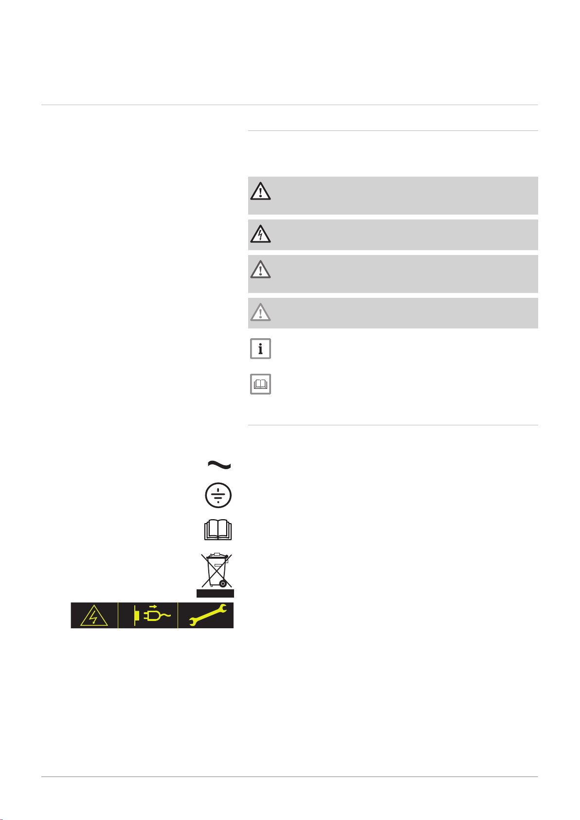
Danger
Risk of dangerous situations that may result in serious personal
injury.
Danger of electric shock
Risk of electric shock.
Warning
Risk of dangerous situations that may result in minor personal
injury.
Caution
Risk of material damage.
Fig.1
Important
Please note: important information.
See
Reference to other manuals or pages in this manual.
2.1.2 Symbols used on the appliance
1 Alternating current.
2 Protective earthing.
3 Before installing and commissioning the appliance, carefully read
the instruction manuals provided.
4 Dispose of used products through an appropriate recovery and
recycling structure.
5 Caution: danger of electric shock, live parts. Disconnect the mains
power prior to carrying out any work.
3 Technical specifications
12 MID _HMI T-control - Gas 120 ACE 7717201 - v03 - 25062019
3 Technical specifications
3.1 Homologations
3.1.1 Standards & Directives
This product complies with the requirements of the following European
directives and standards:
Standards: EN15502
Efficiency Directive 92/42/EC
Low Voltage Directive 2014/35/EU
Generic standard: EN 60335-1
Relevant standard: EN 60335-2-102
Electromagnetic Compatibility Directive 2014/30/EU
Generic standards: EN 61000-6-3, EN 61000-6-1
Relevant Standard: EN 55014
Ecodesign Directive
This product conforms to the requirements of European Directive
2009/125/EC on the ecodesign of energy-related products.
In addition to the legal requirements and guidelines, the supplementary
guidelines in this manual must also be followed.
Supplements or subsequent regulations and guidelines that are valid at
the time of installation shall apply to all regulations and guidelines
specified in this manual.
Warning
The appliance must be installed by a qualified professional in
accordance with applicable local and national regulations.
3.1.2 Factory test
Before leaving the factory, each appliance is tested for the following:
Electrical tests (components, safety).
3.2 Electrical diagram
SCB-02
1
2
3
4 5
BL
YE
RE BK
OR
1
2
3
4 5
BL
YE
RE BK
OR
MW-2000917-01
10 A
L
N
230V/50Hz
BL
G/Y
BR
1
2
3
G/Y
BR
BL
1
2
3
4 5
BL
YE
RE BK
OR
BL
G/Y
BR
BL
G/Y
BR
24V
12 11
BL GR
10 9 8 7 6
OR BK RE YE BL
5 4 3 2 1
OR BK RE YE BL
230V
1 2 3 4 5
G/Y
BR BL
6 7 8 9 10
G/Y
BR BL
WH
BK
RE
YE
BL
GR
OR
BL
YE
RE
BK
OR
CB-09 IF-01
8 9
7
2
3
4
6
5
1
7717201 - v03 - 25062019 MID _HMI T-control - Gas 120 ACE 13
Fig.2
3 Technical specifications
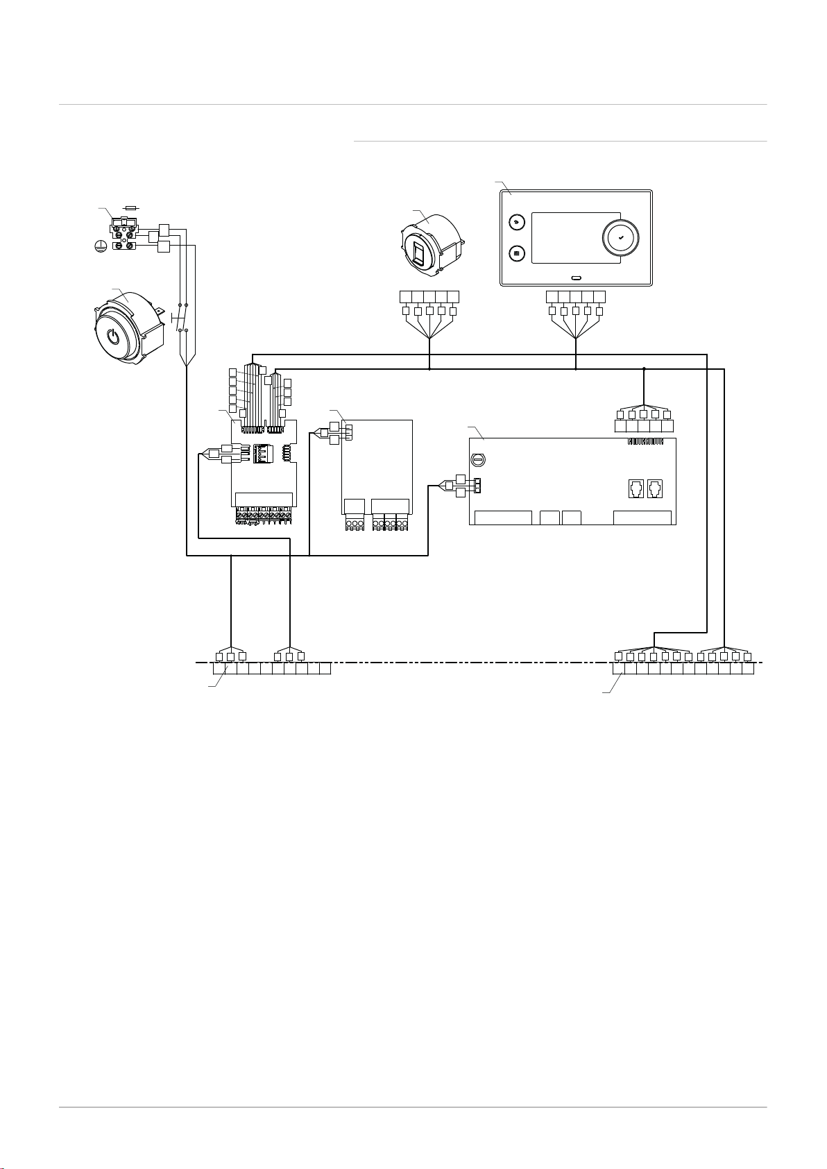
3.2.1 Electrical diagram for the MID control unit HMI T-control
1 MID control panel HMI T-control
2 Service connector, allows the technician to work on
the equipment
3 230 V mains power supply connection with 10 A fuse
4 On/Off switch
5 230 V connector, connection with the boiler
6 24 V connector, connection with the boiler
7 SCB-02 PCB
8 CB-09 PCB
9 IF-01 PCB
BK Black
BL Blue
BR Brown
G/Y Green/Yellow
YE Yellow
OR Orange
GR Green
PI Pink
GY Grey
RD Red
WH White
AD-3001313-01
C No
Nc
Status A
C No
Nc
Status B
N L
+
-
0-10
Tout
N L
N
+
-
0-10
Tdhw Tflow
R-Bus
MW-2000918-01
1
4
3
2
5
7
6
4 Description of the product
14 MID _HMI T-control - Gas 120 ACE 7717201 - v03 - 25062019
4 Description of the product
4.1 General description
The control box is used to control the operation of a Gas 120 ACE boiler.
The box is equipped with a HMI T-control control panel.
4.2
Main components
Fig.3
4.3 PCBs
Fig.4
SCB-02 expansion board
1 Protective cover
2 On/Off switch
3 HMI T-control control panel
4 Service connector, allows the technician to work on the equipment
5 SCB-02 PCB
6 IF-01 PCB
7 CB-09 PCB
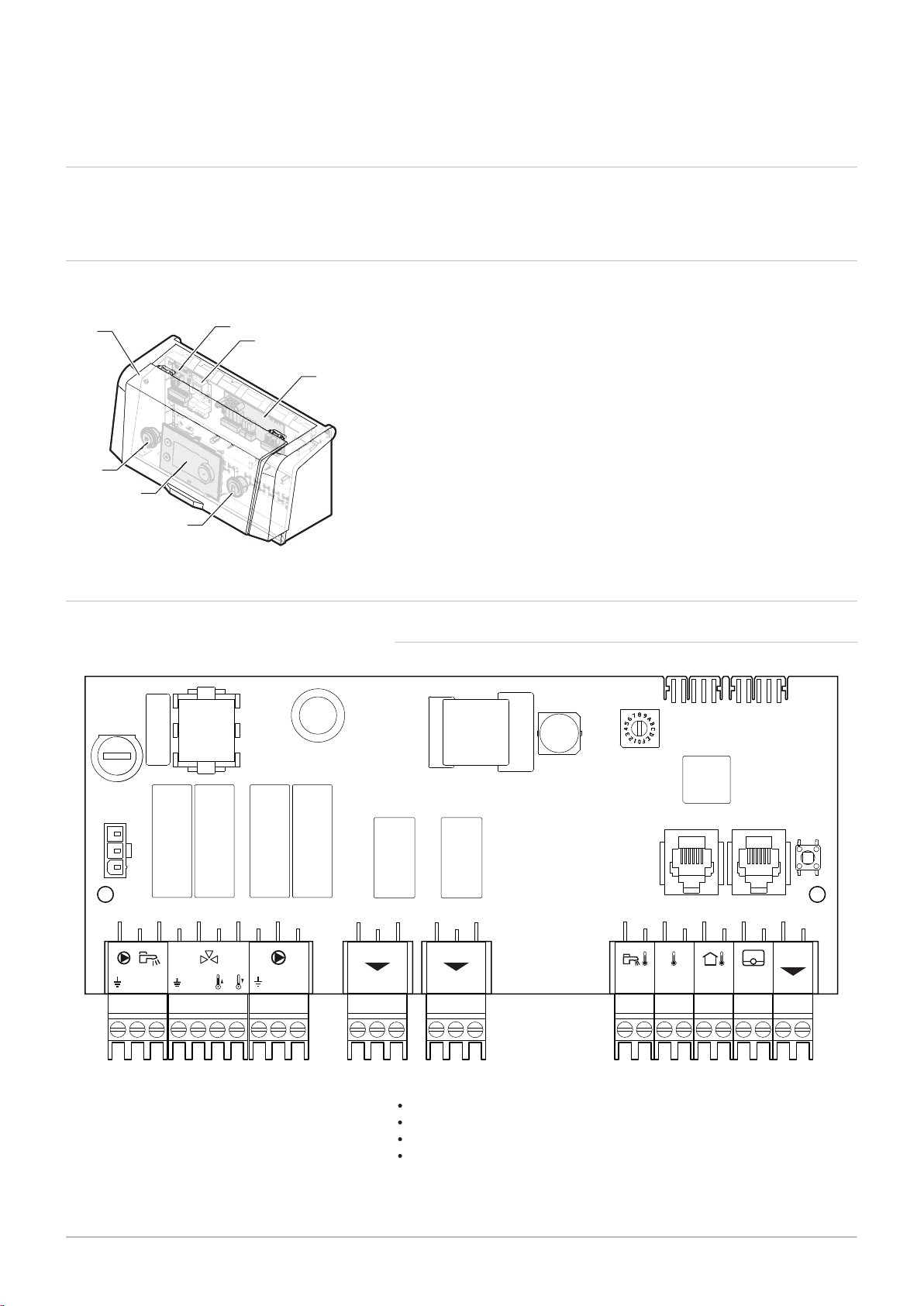
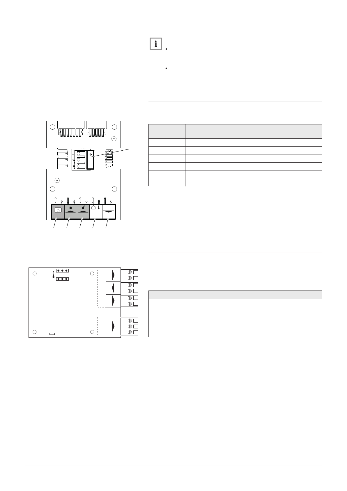
4.3.1 SCB-02 expansion board description
The expansion board SCB-02 has the following features;
control of a (mixing) zone for heating (or cooling)
control of one domestic hot water (DHW) zone
0–10 V output control for a PWM system pump
two potential-free contacts for status notifications
Important
Tout - +BL RL
LN
R-Bu
s
PWM
1
6
MW-2000826-01
2 3 4 5
AD-0000054-01
Status 0-10 0-10
Nc NoC
Nc No OTm 0 + 0 +C
OTm 0 + 0 +
X5
X4
X1
IF-01
%
1
2
7717201 - v03 - 25062019 MID _HMI T-control - Gas 120 ACE 15
If the boiler is fitted with the SCB-02 board, then this is
automatically recognised by the automatic control unit of the
boiler.
On removing this board, the boiler will show an error code. To
prevent this error, carry out an auto-detect immediately after
removing this board.
4.3.2 Description of the CB-09 PCB
4 Description of the product
Fig.5
Fig.6
The CB-09 PCB allows additional inputs to be connected as per the
following table:
Mar
ker
Con
nector
Description
1 R-Bus Not used
2 BL Boiler frost protection (active if contact open)
3 RL Release open contact
4 Tout Not used
5 PWM Modulating pump control connection
6 X4 Modulating pump power connection
4.3.3 Description of the IF-01 PCB
The IF-01 PCB is factory fitted and allows additional inputs such as a
sensor or switch to be connected to the system.
This PCB controls the boiler with the 0-10V signal from an external control
system.
Connector Description
0-10 (input) The 0-10V signal corresponds to a temperature or power
set point, depending on the position of the jumpers
0-10 (output) Output signal indicating the boiler's operating mode
Status Boiler fault reporting contact output
OTm Communication link with the CU-GH-08 PCB
Off
MW-5000756-1
3
4
1
2
5
6
29,4°C29,6°C
51,2°C 6,7°C
21,8°C
29,4°C
1,8 bar
Not Set
None o OFF
OK
I
I
MW-5000763-2
2 4 31
4 Description of the product
16 MID _HMI T-control - Gas 120 ACE 7717201 - v03 - 25062019
4.4 Control panel description
Caution
Do not connect a frost thermostat or room thermostat to the boiler
if using the 0–10 V PCB.
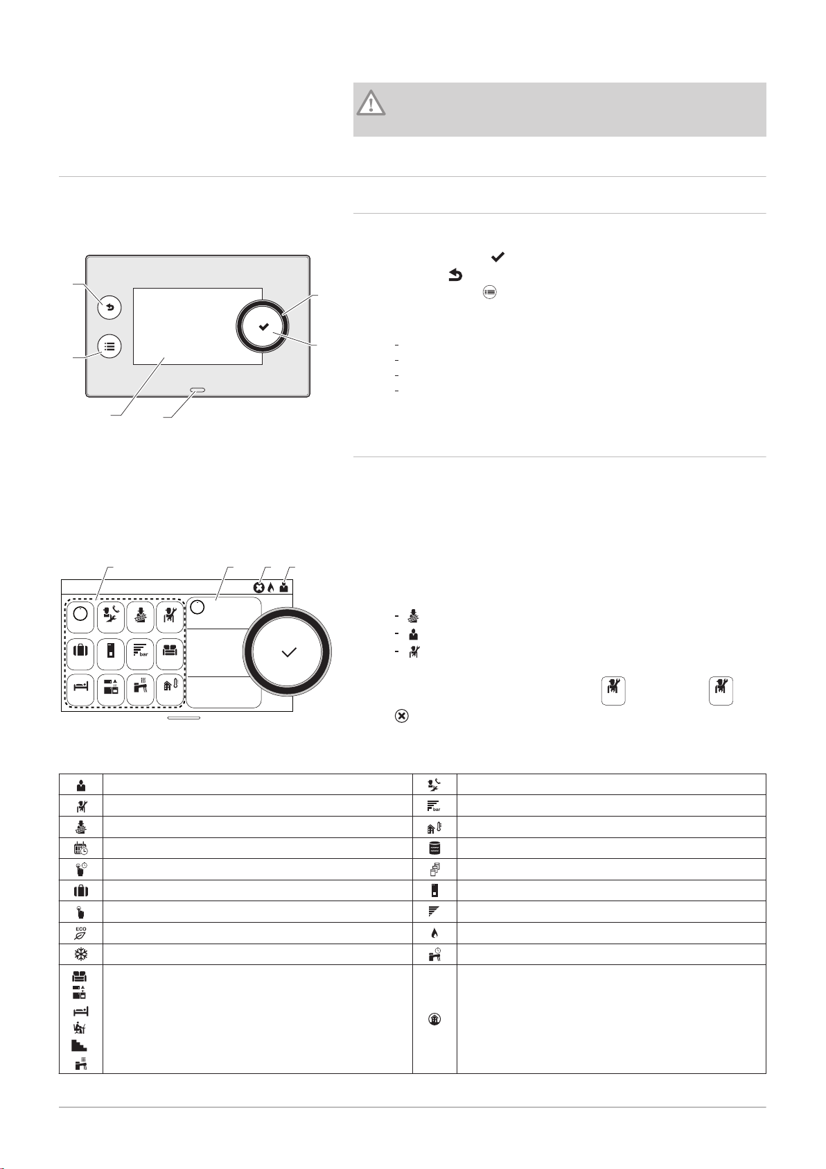
4.4.1 Description of the user interface
Fig.7
Fig.8
1 Rotary knob to select a menu or setting
2
Validation button
3
Back key to return to the previous level or previous menu
4
Main menu key
5 Display screen
6 LED for status indication:
continuous green = normal operation
flashing green = warning
continuous red = shutdown
flashing red = lockout
4.4.2 Description of the main screen
This screen is displayed automatically after the appliance is started up.
The screen goes into standby if no key is pressed for five minutes. Press
one of the buttons on the control panel to exit standby.
1 Symbols
The selected icon is highlighted.
2 Information on the selected icon
3 Navigation level:
: Chimney Sweep level
: User level
: Installer level
This level is reserved for installers and is protected by an access
Tab.1 Symbols
User Level
Installer Level Water pressure
Chimney Sweep level
Timer programme Buffer tank
Timer programme override Cascade
Holiday mode Boiler
Manual mode
Eco mode Burner on
Frost protection mode Domestic hot water override
,
,
Zone icons All zones
,
,
code. When this level is active, the
4
error notification: only visible if an error occurs.
icon becomes On.
Maintenance message
Outdoor temperature sensor
Burner output level

4.5 Standard delivery
7717201 - v03 - 25062019 MID _HMI T-control - Gas 120 ACE 17
4.6 Accessories & options
4 Description of the product
The package contains:
A complete control box for a Gas 120 ACE boiler
Two mounting bolts with two serrated washers
An outdoor temperature sensor
A control box installation, user and service manual
A detailed list of accessories and options can be found in our catalogue.
MW-6000750-02
Manual
1
MW-6000760-01
3
4
2
2
5 Installation
18 MID _HMI T-control - Gas 120 ACE 7717201 - v03 - 25062019
5 Installation
5.1 Installation regulations
Caution
The appliance must be installed and maintained by a certified
professional in accordance with prevailing statutory texts and
codes of practice.
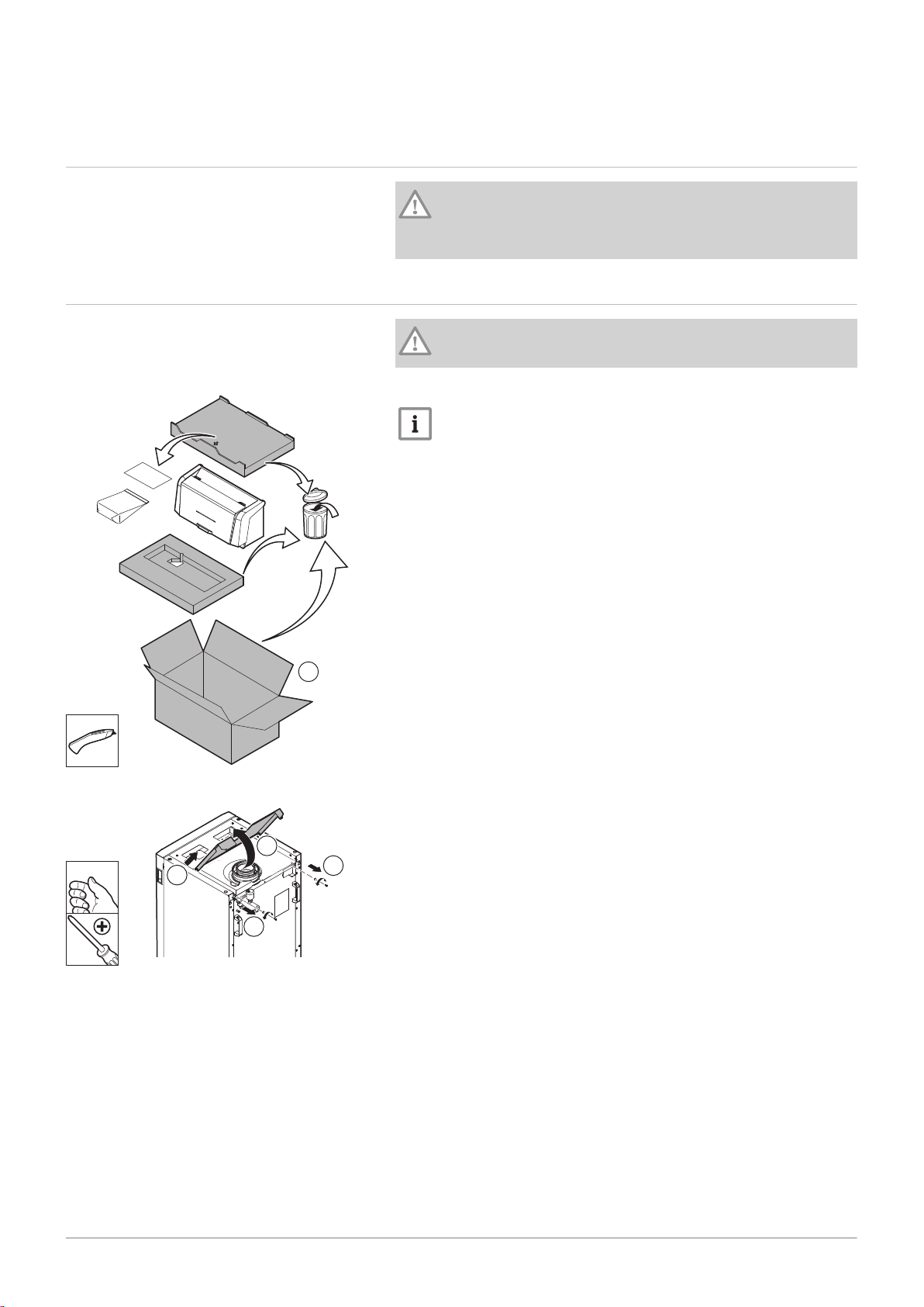
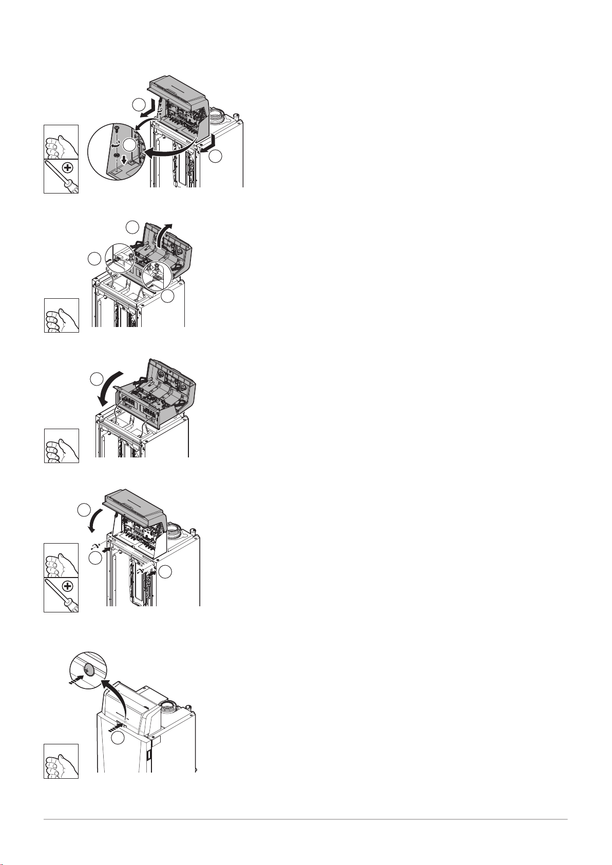
5.2
Fig.9
Unpack and fit the control box
Caution
Wear gloves when handling the control box.
1. Cut and remove the packaging.
Important
The technical documentation is housed in the protective block.
Fig.10
2. Remove the two screws from the boiler's rear top panel.
3. Lift the top panel.
4. Remove the top panel.
MW-2000680-03
5
5
MW-6000762-01
6
6
MW-6000763-02
7
90º
MW-6000764-01
8
5 Installation
7717201 - v03 - 25062019 MID _HMI T-control - Gas 120 ACE 19
Fig.11
Fig.12
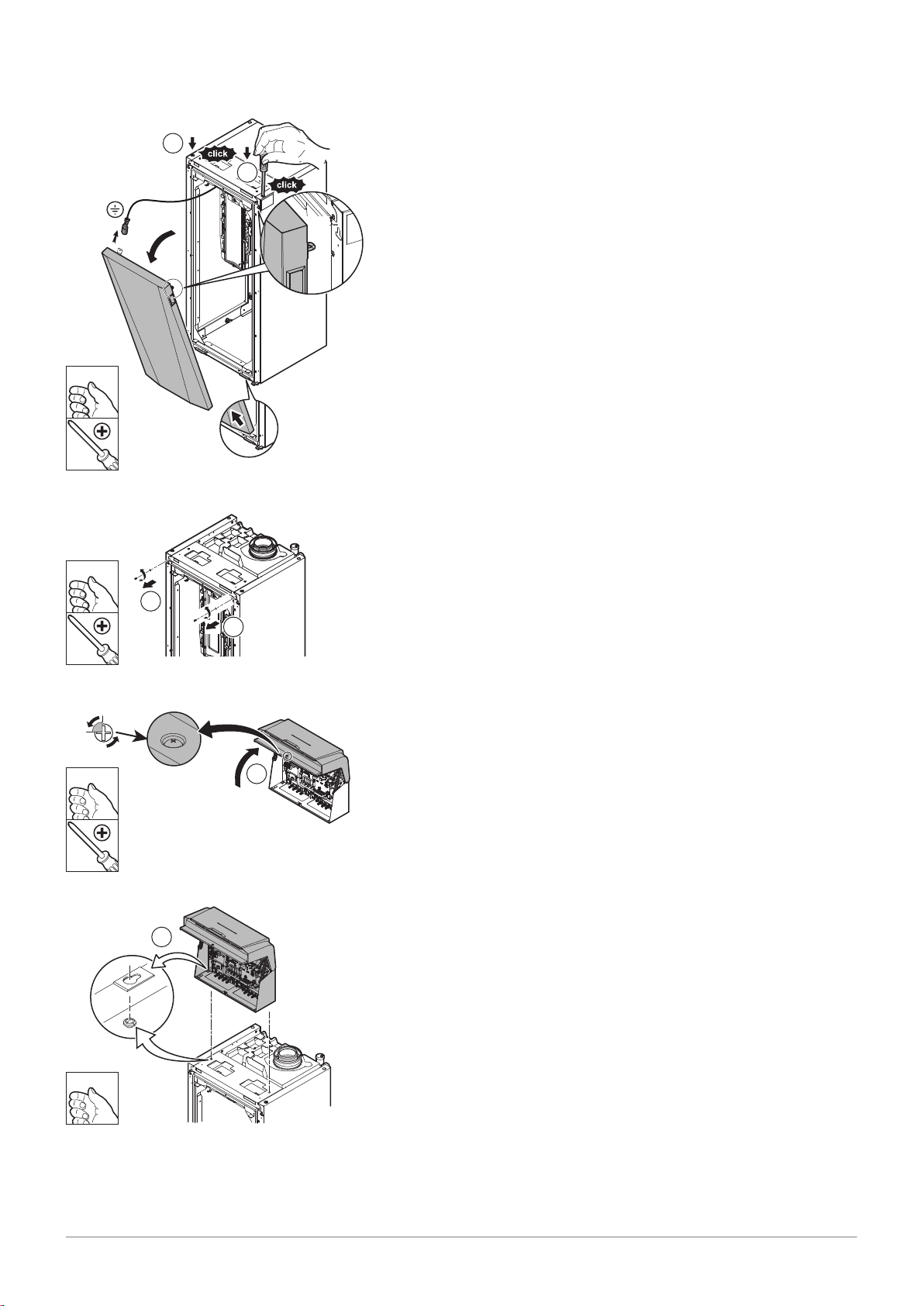
5. Remove the front door.
6. Remove the two retaining screws from the front top panel.
Fig.13
Fig.14
7. Open the control box cover.
8. Align the boiler's tapered interlocks with the notches on the control
box.
MW-6000765-02
9
9
10
MW-6000766-02
230V
24V
11
12
12
MW-6000767-01
13
MW-6000768-02
14
14
15
MW-6000769-01
16
5 Installation
20 MID _HMI T-control - Gas 120 ACE 7717201 - v03 - 25062019
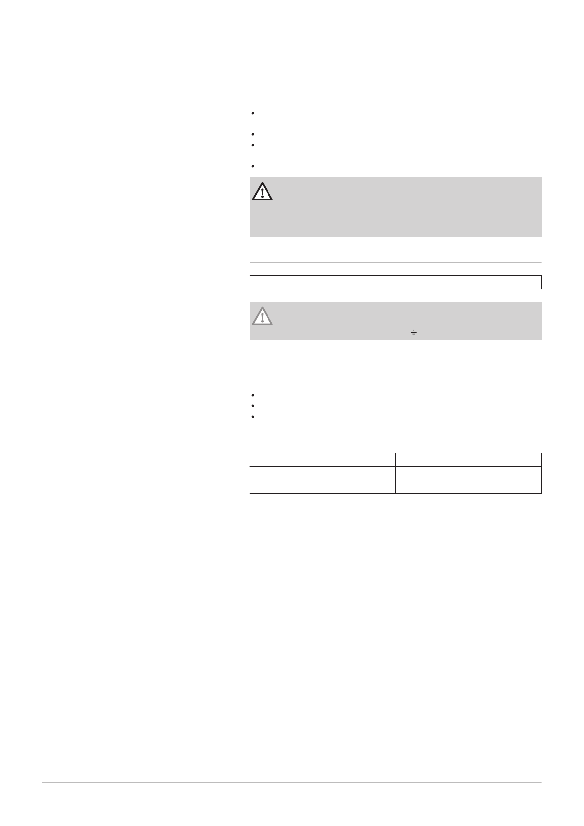
Fig.15
Fig.16
Fig.17
9. Fit the box and slide it forwards.
10. Lock the box using the two screws and toothed washers supplied in
the bag with the manual.
11. Tilt the assembly backwards.
12. Connect the two connectors from the boiler to the connectors on the
control box.
13. Move the control box back to its original position by tilting it forwards.
Fig.18
Fig.19
14. Lock the control box in position using the two screws and the toothed
washers.
15. Close the box cover.
16. Lock the cover by pressing on the screw head.
17. Refit the front door and the rear top panel and refit the two screws and
the toothed washers.
5.3 Electrical connections
7717201 - v03 - 25062019 MID _HMI T-control - Gas 120 ACE 21
5 Installation
5.3.1 Recommendations
Only qualified professionals may carry out electrical connections, always
with the power off.
Earth the appliance before making any electrical connections.
Power the appliance via a circuit that includes an omni-polar switch with
contact opening distance of 3 mm or more.
When making electrical connections to the mains, respect the polarities.
Danger
Position the various electrical cables in such a way that they never
touch the heating pipes.
Keep the various electrical cables far enough from the heating
pipes so that they cannot be damaged by the effect of the heat.
5.3.2 Electrical power supply
Power supply voltage 230 V AC/50 Hz
Caution
Please ensure the polarities shown on the terminals are followed,
i.e live (L), neutral (N) and earth ( )
5.3.3 Recommended cable cross section
Decide on the cable according to the following information:
Distance of the appliance from the power source.
Upstream protection.
Neutral operating conditions.
Tab.2 Specifications of the power cable and the power source
Cable cross section 3 x 1.5 mm²
Curve C (circuit breaker) 10 A
Differential 30 mA
MW-2000830-02
1
2
1
MW-2000831-01
3
MW-2000832-01
4
90º
5 Installation
22 MID _HMI T-control - Gas 120 ACE 7717201 - v03 - 25062019
Caution
Provide a separate power supply for the pump and a power
switch, if necessary.
The output available per outlet is 450 W (2 A, with cos ϕ = 0.7)
and the inrush current must be less that 16 A. If the load exceeds
either of these values, the control must be relayed using a
contactor that must in no circumstances be installed in the control
panel. The sum of the currents from all outlets must not exceed
5 A.
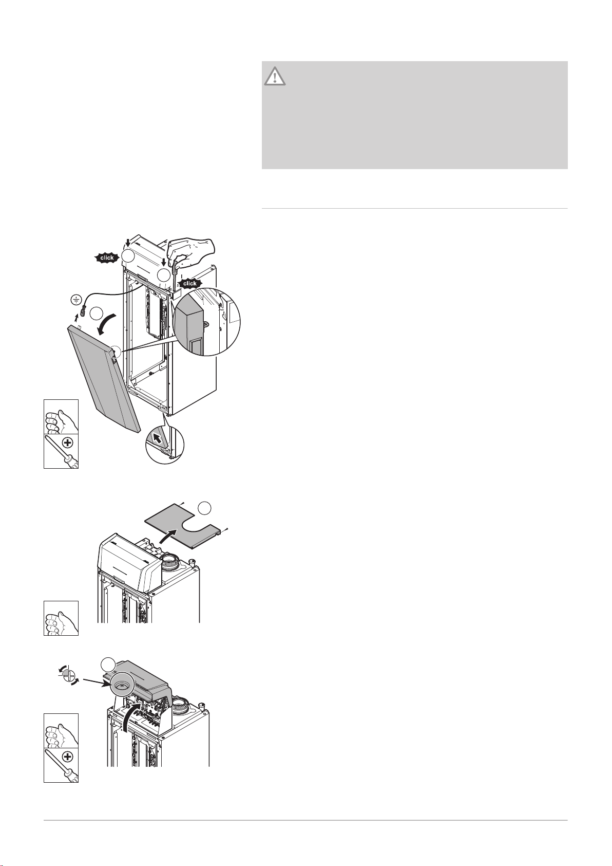
5.3.4 Cable routing and access to the connection terminal
blocks
Fig.20
Fig.21
1. Unlock the front door.
2. Tilt and lift the door to remove it.
3. Remove the two screws and dismantle the rear top panel.
Fig.22
4. Unlock and open the cover on the control box.
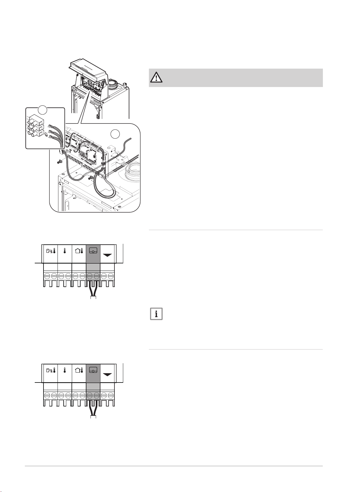
Fig.23
MW-2000833-02
Sensor
230V
5
230V
L
N
6
MW-2000919-01
OT
0-10
Tout
+
-
0-10
Tdhw
Tflow
R-Bus
MW-2000920-01
Tk
0-10
Tout
+
-
0-10
Tdhw
Tflow
R-Bus
7717201 - v03 - 25062019 MID _HMI T-control - Gas 120 ACE 23
5 Installation
5. Ensure that the cables are correctly routed and affix the cable(s) using
the traction arrester devices.
230 V 230 V circuits (left)
Sensor Sensor circuits (right)
Danger
Separate the sensor cables from the 230 V circuit cables.
6. Connect the boiler's main power supply cable.
Fig.24 to SCB-02
Fig.25 to SCB-02
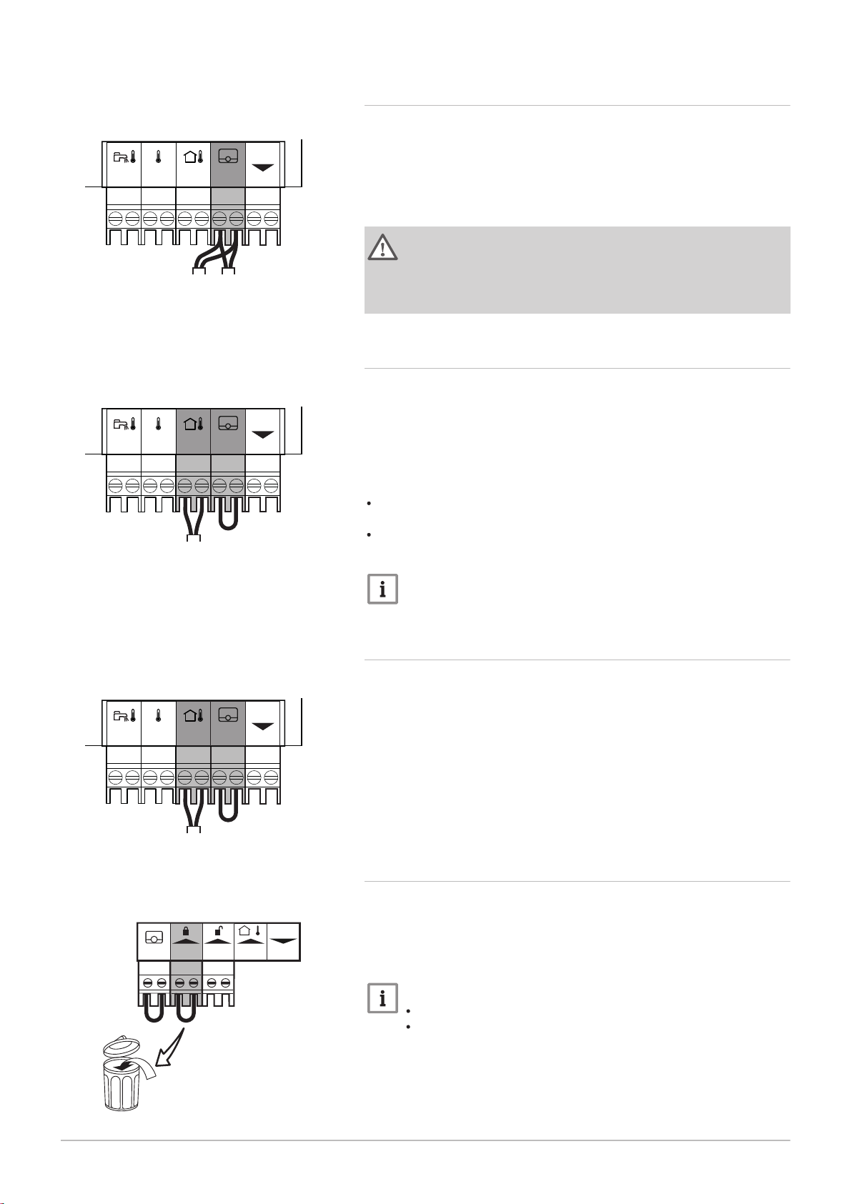
5.3.5 Connecting a modulating thermostat
The boiler is fitted with an R-Bus connection as standard. This connection
is also compatible with OpenTherm. This enables the user to connect
OpenTherm modulating thermostats (such as iSense Pro) or R-Bus
thermostats (such as eTwist) without any further adjustments being made
to the appliance. The boiler is also suitable for OpenTherm Smart Power.
1. In the case of a room thermostat: install the thermostat in a reference
room.
2. Connect the two-wire cable for the thermostat to the R-Bus terminals
for the connector. It does not matter which wire is connected to which
terminal block.
Important
If the domestic hot water temperature can be set on the
OpenTherm thermostat, the boiler will supply this temperature,
with the value set in the boiler as a maximum.
5.3.6 Connecting an on/off thermostat
The boiler is suitable for connection to a two-wire on/off room thermostat
(Tk).
1. Fit the thermostat in a reference room.
2. Connect the two-wire cable for the thermostat to the R-Bus terminals
of the connector. It does not matter which wire is connected to which
terminal block.
MW-2000921-01
TvTk
0-10
Tout
+
-
0-10
Tdhw
Tflow
R-Bus
MW-2000922-01
0-10
Tout
+
-
0-10
Tdhw
Tflow
R-Bus
MW-2000922-01
0-10
Tout
+
-
0-10
Tdhw
Tflow
R-Bus
MW-2000873-01
ToutBL RL
R-Bus
- +
PWM
5 Installation
24 MID _HMI T-control - Gas 120 ACE 7717201 - v03 - 25062019
5.3.7 Frost protection combined with on/off thermostat
Fig.26 to SCB-02
Fig.27 to SCB-02
When an on/off thermostat is used, the pipes and radiators in a frostsensitive room can be protected by a frost thermostat. The radiator valve
in the frost-sensitive room must be open.
1. Place a frost thermostat (Tv) in a frost-sensitive room (e.g. a garage).
2. Connect the frost thermostat (Tv) and the on/off thermostat (Tk) in
parallel to the
R-Bus terminals of the connector.
Warning
If a Remeha eTwist or OpenTherm thermostat is used, a frost
thermostat cannot be connected in parallel to the R-Bus terminals.
In this case, ensure frost protection of the central heating system
in combination with an outside sensor.
5.3.8 Frost protection combined with outdoor temperature sensor
The central heating system can also be protected against frost in
combination with an outdoor temperature sensor. The radiator valve in the
frost-sensitive room must be open.
1. Connect the outdoor temperature sensor to the Tout terminals of the
connector.
The frost protection works as follows with an outdoor temperature sensor:
If the outdoor temperature is lower than -10 °C: heat demand from the
boiler.
If the outdoor temperature is higher than -10 °C: no heat demand from
the boiler.
Fig.28 to SCB-02
Fig.29 to CB-09
Important
The outdoor temperature before the start of frost protection can be
changed with the AP080 parameter.
5.3.9 Connecting an outdoor temperature sensor
An outdoor temperature sensor (accessory) can be connected to the Tout
terminals of the connector. If the boiler is equipped with an on/off
thermostat, the temperature is controlled using the setpoint of the internal
heating curve (F). Various parameter settings can be used to change the
internal heating curve.
1. Connect the plug from the outdoor temperature sensor to the Tout
terminal.
5.3.10 Blocking input
The boiler has a blocking input (normally closed contact). This input
relates to the BL terminals of the connector.
If this contact is opened, the boiler will be blocked or locked out.
Change the function of the input by configuring the AP001 parameter.
Important
Remove the bridge if this input is used.
Only suitable for potential-free contacts.
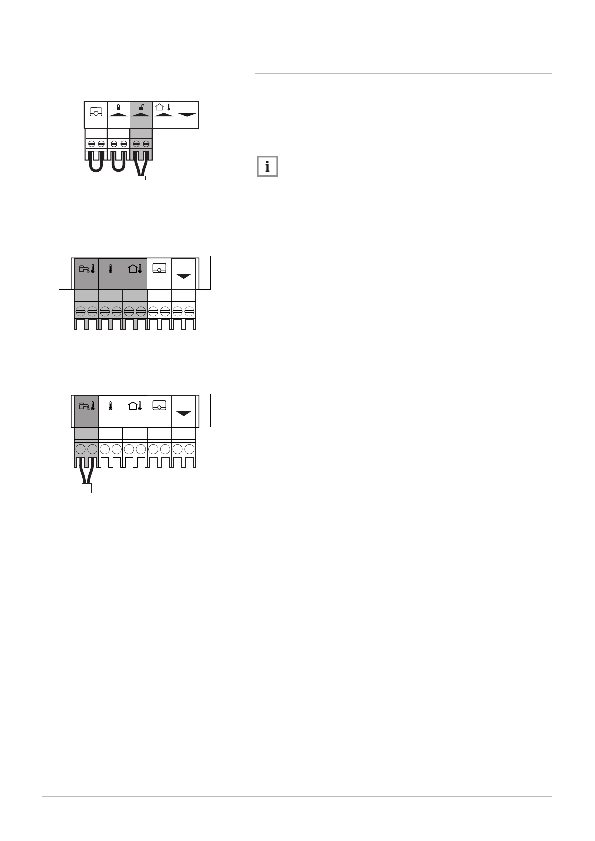
5.3.11 Release input
MW-2000874-01
T
out
BL RL
R-Bus
- +
PWM
MW-2000932-01
0-10
Tout
+
-
0-10
Tdhw
Tflow
R-Bus
MW-2000923-01
0-10
Tout
+
-
0-10
Tdhw
Tflow
R-Bus
7717201 - v03 - 25062019 MID _HMI T-control - Gas 120 ACE 25
5 Installation
Fig.30
Fig.31
to CB-09
The boiler has a release input (normally open contact). This input relates
to the RL terminals of the connection terminal block.
If this contact is closed when there is a heat demand, the boiler will be
blocked after a waiting time.
Change the waiting time of the input by configuring the AP008 parameter.
Important
Only suitable for potential-free contacts.
5.3.12 Connecting external sensors
Tdhw
Tflow
The sensor connection contacts are dry contacts.
Tank sensor (NTC 10 k Ohm)
Boiler flow temperature sensor (NTC 10 k Ohm)
Tout
Outdoor temperature sensor (NTC 10 k Ohm)
5.3.13 Connecting a tank sensor or thermostat
Fig.32 to SCB-02
A sensor or thermostat can be connected to the Tdhw terminals of the
connector.
1. Connect the domestic hot water sensor or the tank thermostat to the
Tdhw connector.
MW-2000878-02
Tout - +BL RL
R-Bus
PWM
X4
CB-09
Tout - +BL RL
R-Bus
PWM
CB-09
MW-2000879-02
X4
5 Installation
26 MID _HMI T-control - Gas 120 ACE 7717201 - v03 - 25062019
5.3.14 Connecting a PWM pump
Fig.33
to CB-09
1. Connect the modulating pump to the X4 terminal for the power section
and to the PWM terminal for the control section, respecting the pump
polarity.
5.3.15 Connecting a standard pump
Fig.34 to CB-09
1. Connect the pump to the X4 terminal on the PCB.
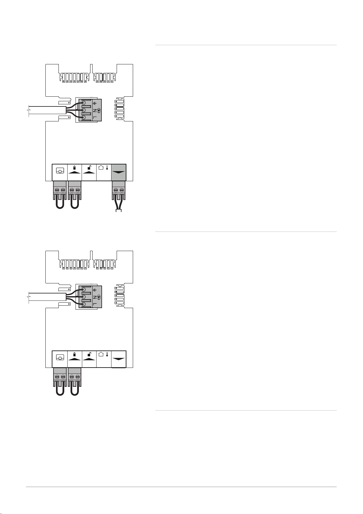
5.3.16
Connecting a domestic hot water (DHW) pump
Connecting a domestic hot water (DHW) pump. The maximum power
consumption is 300 VA.
AD-4000123-01
N L
AD-4000015-02
N
AD-3001306-01
N L
AD-3001312-01
C No
Nc
Status A
C No
Nc
Status B
AD-3001305-01
+
-
0-10
5 Installation
7717201 - v03 - 25062019 MID _HMI T-control - Gas 120 ACE 27
Fig.35
DHW pump connector
Fig.36 Three-way valve connector
Connect the pump as follows:
Earth
N
Neutral
L
Phase
5.3.17 Connecting a three-way valve
Connecting a three-way valve (230 VAC). The connection can be used for
a boiler group (zone).
Connect the three-way valve as follows:
Earth
N
Neutral
Open
Closed
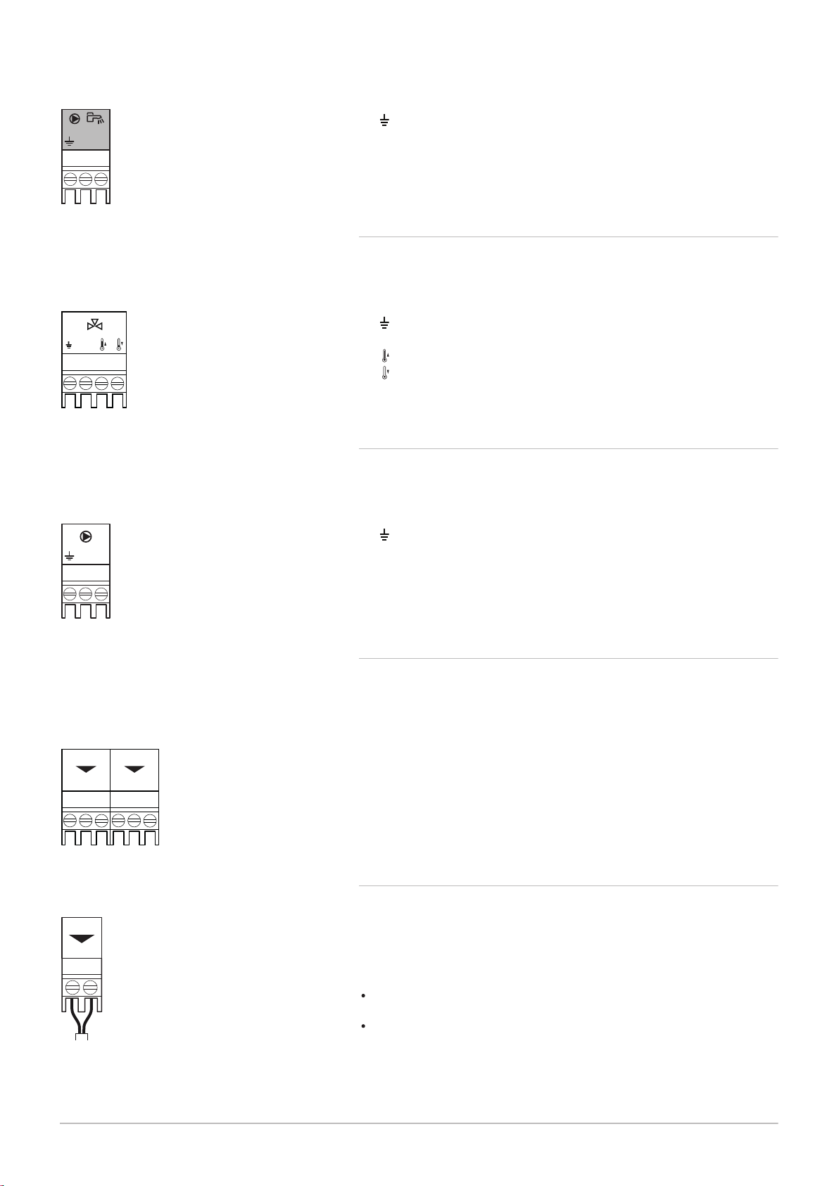
5.3.18
Connecting a system pump for mix group (zone) The maximum power
consumption is 300 VA.
Connecting a system pump for mix group
Fig.37 Pump connector
Fig.38 Status notifications
Fig.39 0–10 V output connector
Connect the pump as follows:
Earth
N
Neutral
L
Phase
5.3.19 Connecting status notifications
The two potential-free contacts, Status, can be configured as required.
Depending on the setting, a particular status can be transmitted by the
boiler.
Connect a relais as follows:
Nc
Normally closed contact. Contact will open when status occurs.
C
Main contact.
No
Normally opened contact. Contact will close when status occurs.
Select the desired status notification (setting) using parameter EP018 and
EP019.
5.3.20 Connecting 0–10 V output
The 0-10 contact can be used to connect a PWM system pump. The
speed of the pump is modulated based on the signal received from the
boiler. Depending on the make and type of pump, the pump can be
controlled by a 0–10 V or a PWM signal.
Connect the system pump controller to connector 0-10.
Select the type of signal that will be sent from the boiler using the
parameter EP029.
Select the type of signal that controls the pump using the parameter
EP028.
AD-0000054-01
Status 0-10 0-10
Nc NoC
Nc No OTm 0 + 0 +C
OTm 0 + 0 +
X5
X4
X1
IF-01
%
1
2
AD-0000055-01
1
2
%
2 2
5 Installation
28 MID _HMI T-control - Gas 120 ACE 7717201 - v03 - 25062019
Caution
If possible, use the pump modulation signal. This provides the
most accurate pump control.
If the automatic burner unit does not support pump modulation,
the pump will behave as an on/off pump.
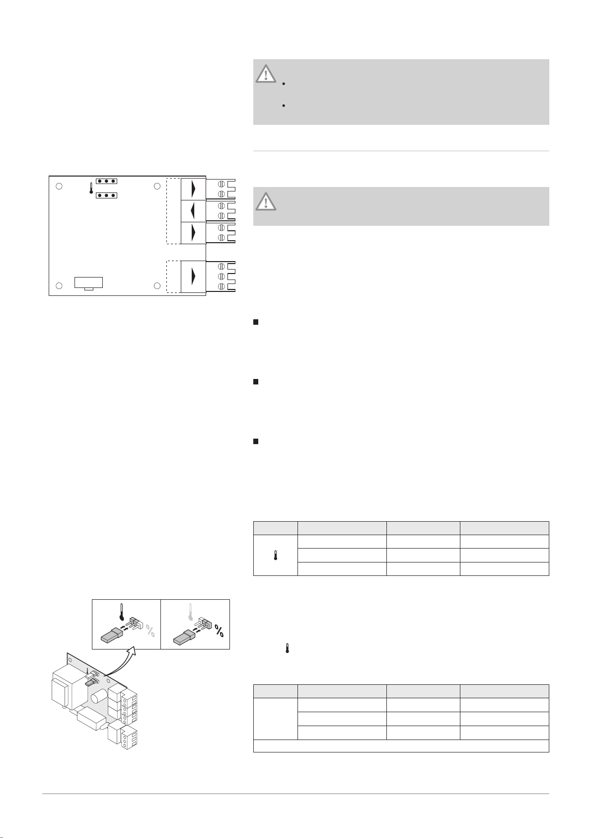
5.3.21 Connection options for the expansion PCB - IF-01
Fig.40 IF-01 PCB
The expansion board IF-01 is pre-installed in the instrument box as
standard.
Caution
Do not connect a frost thermostat or room thermostat to the boiler
if using the 0–10 V control PCB.
Connecting the status relay (Nc)
If the boiler locks out, a relay is de-energised and the alarm can be
transmitted via a potential-free contact (maximum 230 V, 1 A) on terminals
Nc and C of the connector.
Connection (OTm)
The interface uses OpenTherm to communicate with the boiler control
unit. To make this possible, the OTm connection must be connected to the
OpenTherm input of the boiler control unit.OTm
Analogue input (0-10 V)
A choice can be made with this control between control based on
temperature or heat output. The two controls are described briefly below.
1. Connect the input signal to terminals 0–10 of the connector.
Tab.3 Temperature-based control (°C)
Jumper 2 Input signal (V) Temperature °C Description
0–1.5 0–15 Boiler off
1.5–1.8 15–18 Hysteresis
1.8–10 18–100 Desired temperature
Fig.41 Switch jumper (2)
The 0–10 V signal controls the boiler supply temperature. This control
modulates on the basis of flow temperature. The output varies between
the minimum and maximum value on the basis of the flow temperature set
point calculated by the controller.
A jumper (2) on the interface is used to select either temperature-based
control ( ) or output-based control (%).
Tab.4 Control based on heat output
Jumper 2 Input signal (V) Heat output (%) Description
(1)
0–2.0
%
2.0–2.2
2.0–10
(1) Dependent on the minimum modulation depth (set speeds, standard 20%)
(1)
(1)
0–20 Boiler off
20–22 Hysteresis
20–100 Desired heat output
AD-0000056-01
1
2
%
1 1
AD-0001177-01
3
4
5
1
2
5 Installation
7717201 - v03 - 25062019 MID _HMI T-control - Gas 120 ACE 29
The 0–10 V signal controls the boiler output. This control modulates on the
basis of the heat output. The minimum output is linked to the boiler's
modulation depth. The output varies between the minimum and maximum
value on the basis of the value defined by the controller.
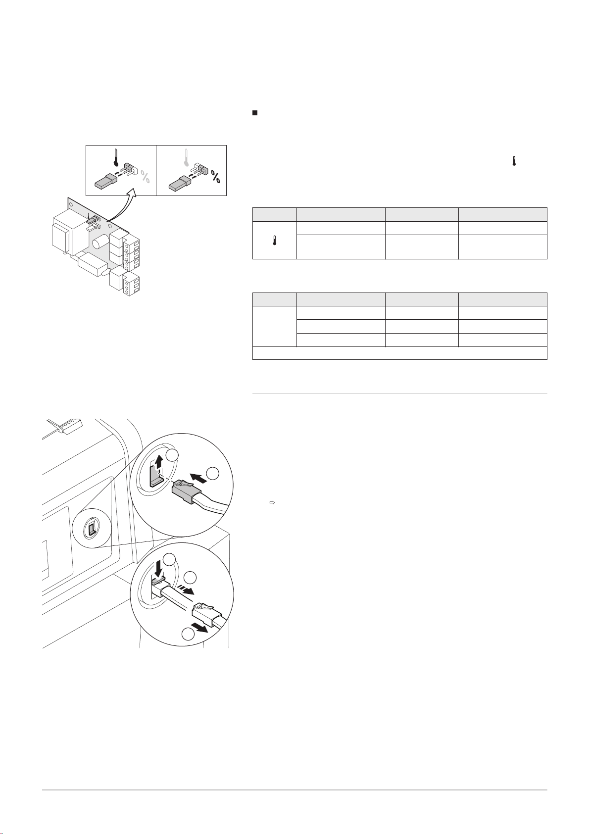
Analogue output (0–10 V)
Fig.42
Switch jumper (1)
Fig.43 Connecting an interface connector
This feedback can be based on temperature or heat output. The two
controls are described briefly below.
A jumper (1) on the interface is used to select either temperature ( ) or
output (%).
Tab.5 Temperature message
Jumper 1 Output signal (V) Temperature °C Description
0.5 – Alarm
1–10 10–100 Supplied tempera
ture
Tab.6 Output message
Jumper 2 Output signal (V) Heat output (%) Description
0 0–15 Boiler off
0.5 15–20 Alarm
%
(1)
2.0–10
(1) Dependent on the minimum modulation depth (set speeds, standard 20%)
20–100 Supplied heat output
5.3.22 Connecting a PC/laptop
There is a Service connector next to the control panel. A Recom interface
can be used to connect a PC, laptop or a Smart Service Tool here. Using
the Recom PC/laptop service software, you can enter, change and read
out various boiler settings.
Connecting an interface connector:
1. Move the Service connector slide upwards.
2. Push the interface connector into place. It should snap shut with a
click.
Disconnect the interface connector again:
3. Maintain slight tension on the interface connector
4. Push the slide downwards. The interface connector will now be
released.
5. Pull the interface connector from the connector.
 Loading...