

REMEHA GAS 120 ACE Series, GAS 120 ACE - 65, GAS 120 ACE - 90, GAS 120 ACE - 115 User Manual

MW-2000881-02
en
MID control box equipped with a HMI T-control
for Gas 120 ACE boiler

Dear Customer,
Thank you very much for buying this appliance.
Please read through the manual carefully before using the product, and keep it in a safe place for later reference. In order to
ensure continued safe and efficient operation we recommend that the product is serviced regularly. Our service and customer
service organisation can assist with this.
We hope you enjoy years of problem-free operation with the product.

Contents
7717201 - v03 - 25062019 MID _HMI T-control - Gas 120 ACE 3
Contents
1 Safety . . . . . . . . . . . . . . . . . . . . . . . . . . . . . . . . . . . . . . . . . . . . . . . . . . . . . . . . . . . . . . . . . . . . . . . . . . . . . . . . . . . . . . . . . . . . 6
1.1 General safety instructions . . . . . . . . . . . . . . . . . . . . . . . . . . . . . . . . . . . . . . . . . . . . . . . . . . . . . . . . . . . . . . . . . . . . . . . 6
1.1.1 Safety instructions for the installer . . . . . . . . . . . . . . . . . . . . . . . . . . . . . . . . . . . . . . . . . . . . . . . . . . . . . . . . . .6
1.1.2 Safety instructions for the user . . . . . . . . . . . . . . . . . . . . . . . . . . . . . . . . . . . . . . . . . . . . . . . . . . . . . . . . . . . . 7
1.2 Recommendations . . . . . . . . . . . . . . . . . . . . . . . . . . . . . . . . . . . . . . . . . . . . . . . . . . . . . . . . . . . . . . . . . . . . . . . . . . . . . 8
1.3 Liabilities . . . . . . . . . . . . . . . . . . . . . . . . . . . . . . . . . . . . . . . . . . . . . . . . . . . . . . . . . . . . . . . . . . . . . . . . . . . . . . . . . . . . . 9
1.3.1 Manufacturer's liability . . . . . . . . . . . . . . . . . . . . . . . . . . . . . . . . . . . . . . . . . . . . . . . . . . . . . . . . . . . . . . . . . . . 9
1.3.2 Installer's liability . . . . . . . . . . . . . . . . . . . . . . . . . . . . . . . . . . . . . . . . . . . . . . . . . . . . . . . . . . . . . . . . . . . . . . . 9
1.3.3 User's liability . . . . . . . . . . . . . . . . . . . . . . . . . . . . . . . . . . . . . . . . . . . . . . . . . . . . . . . . . . . . . . . . . . . . . . . . . .9
2 About this manual . . . . . . . . . . . . . . . . . . . . . . . . . . . . . . . . . . . . . . . . . . . . . . . . . . . . . . . . . . . . . . . . . . . . . . . . . . . . . . . . . . 11
2.1 Symbols used . . . . . . . . . . . . . . . . . . . . . . . . . . . . . . . . . . . . . . . . . . . . . . . . . . . . . . . . . . . . . . . . . . . . . . . . . . . . . . . . 11
2.1.1 Symbols used in the manual . . . . . . . . . . . . . . . . . . . . . . . . . . . . . . . . . . . . . . . . . . . . . . . . . . . . . . . . . . . . . 11
2.1.2 Symbols used on the appliance . . . . . . . . . . . . . . . . . . . . . . . . . . . . . . . . . . . . . . . . . . . . . . . . . . . . . . . . . . .11
3 Technical specifications . . . . . . . . . . . . . . . . . . . . . . . . . . . . . . . . . . . . . . . . . . . . . . . . . . . . . . . . . . . . . . . . . . . . . . . . . . . . . 12
3.1 Homologations . . . . . . . . . . . . . . . . . . . . . . . . . . . . . . . . . . . . . . . . . . . . . . . . . . . . . . . . . . . . . . . . . . . . . . . . . . . . . . . 12
3.1.1 Standards & Directives . . . . . . . . . . . . . . . . . . . . . . . . . . . . . . . . . . . . . . . . . . . . . . . . . . . . . . . . . . . . . . . . . 12
3.1.2 Factory test . . . . . . . . . . . . . . . . . . . . . . . . . . . . . . . . . . . . . . . . . . . . . . . . . . . . . . . . . . . . . . . . . . . . . . . . . . 12
3.2 Electrical diagram . . . . . . . . . . . . . . . . . . . . . . . . . . . . . . . . . . . . . . . . . . . . . . . . . . . . . . . . . . . . . . . . . . . . . . . . . . . . . 13
3.2.1 Electrical diagram for the MID control unit HMI T-control . . . . . . . . . . . . . . . . . . . . . . . . . . . . . . . . . . . . . . . 13
4 Description of the product . . . . . . . . . . . . . . . . . . . . . . . . . . . . . . . . . . . . . . . . . . . . . . . . . . . . . . . . . . . . . . . . . . . . . . . . . . . . 14
4.1 General description . . . . . . . . . . . . . . . . . . . . . . . . . . . . . . . . . . . . . . . . . . . . . . . . . . . . . . . . . . . . . . . . . . . . . . . . . . . .14
4.2 Main components . . . . . . . . . . . . . . . . . . . . . . . . . . . . . . . . . . . . . . . . . . . . . . . . . . . . . . . . . . . . . . . . . . . . . . . . . . . . . 14
4.3 PCBs . . . . . . . . . . . . . . . . . . . . . . . . . . . . . . . . . . . . . . . . . . . . . . . . . . . . . . . . . . . . . . . . . . . . . . . . . . . . . . . . . . . . . . .14
4.3.1 SCB-02 expansion board description . . . . . . . . . . . . . . . . . . . . . . . . . . . . . . . . . . . . . . . . . . . . . . . . . . . . . . 14
4.3.2 Description of the CB-09 PCB . . . . . . . . . . . . . . . . . . . . . . . . . . . . . . . . . . . . . . . . . . . . . . . . . . . . . . . . . . . . 15
4.3.3 Description of the IF-01 PCB . . . . . . . . . . . . . . . . . . . . . . . . . . . . . . . . . . . . . . . . . . . . . . . . . . . . . . . . . . . . .15
4.4 Control panel description . . . . . . . . . . . . . . . . . . . . . . . . . . . . . . . . . . . . . . . . . . . . . . . . . . . . . . . . . . . . . . . . . . . . . . . 16
4.4.1 Description of the user interface . . . . . . . . . . . . . . . . . . . . . . . . . . . . . . . . . . . . . . . . . . . . . . . . . . . . . . . . . . 16
4.4.2 Description of the main screen . . . . . . . . . . . . . . . . . . . . . . . . . . . . . . . . . . . . . . . . . . . . . . . . . . . . . . . . . . . 16
4.5 Standard delivery . . . . . . . . . . . . . . . . . . . . . . . . . . . . . . . . . . . . . . . . . . . . . . . . . . . . . . . . . . . . . . . . . . . . . . . . . . . . . 17
4.6 Accessories & options . . . . . . . . . . . . . . . . . . . . . . . . . . . . . . . . . . . . . . . . . . . . . . . . . . . . . . . . . . . . . . . . . . . . . . . . . .17
5 Installation . . . . . . . . . . . . . . . . . . . . . . . . . . . . . . . . . . . . . . . . . . . . . . . . . . . . . . . . . . . . . . . . . . . . . . . . . . . . . . . . . . . . . . . . 18
5.1 Installation regulations . . . . . . . . . . . . . . . . . . . . . . . . . . . . . . . . . . . . . . . . . . . . . . . . . . . . . . . . . . . . . . . . . . . . . . . . . 18
5.2 Unpack and fit the control box . . . . . . . . . . . . . . . . . . . . . . . . . . . . . . . . . . . . . . . . . . . . . . . . . . . . . . . . . . . . . . . . . . . 18
5.3 Electrical connections . . . . . . . . . . . . . . . . . . . . . . . . . . . . . . . . . . . . . . . . . . . . . . . . . . . . . . . . . . . . . . . . . . . . . . . . . . 21
5.3.1 Recommendations . . . . . . . . . . . . . . . . . . . . . . . . . . . . . . . . . . . . . . . . . . . . . . . . . . . . . . . . . . . . . . . . . . . . .21
5.3.2 Electrical power supply . . . . . . . . . . . . . . . . . . . . . . . . . . . . . . . . . . . . . . . . . . . . . . . . . . . . . . . . . . . . . . . . . 21
5.3.3 Recommended cable cross section . . . . . . . . . . . . . . . . . . . . . . . . . . . . . . . . . . . . . . . . . . . . . . . . . . . . . . . .21
5.3.4 Cable routing and access to the connection terminal blocks . . . . . . . . . . . . . . . . . . . . . . . . . . . . . . . . . . . . .22
5.3.5 Connecting a modulating thermostat . . . . . . . . . . . . . . . . . . . . . . . . . . . . . . . . . . . . . . . . . . . . . . . . . . . . . . .23
5.3.6 Connecting an on/off thermostat . . . . . . . . . . . . . . . . . . . . . . . . . . . . . . . . . . . . . . . . . . . . . . . . . . . . . . . . . . 23
5.3.7 Frost protection combined with on/off thermostat . . . . . . . . . . . . . . . . . . . . . . . . . . . . . . . . . . . . . . . . . . . . . 24
5.3.8 Frost protection combined with outdoor temperature sensor . . . . . . . . . . . . . . . . . . . . . . . . . . . . . . . . . . . . 24
5.3.9 Connecting an outdoor temperature sensor . . . . . . . . . . . . . . . . . . . . . . . . . . . . . . . . . . . . . . . . . . . . . . . . . 24
5.3.10 Blocking input . . . . . . . . . . . . . . . . . . . . . . . . . . . . . . . . . . . . . . . . . . . . . . . . . . . . . . . . . . . . . . . . . . . . . . . . 24
5.3.11 Release input . . . . . . . . . . . . . . . . . . . . . . . . . . . . . . . . . . . . . . . . . . . . . . . . . . . . . . . . . . . . . . . . . . . . . . . . .25
5.3.12 Connecting external sensors . . . . . . . . . . . . . . . . . . . . . . . . . . . . . . . . . . . . . . . . . . . . . . . . . . . . . . . . . . . . . 25
5.3.13 Connecting a tank sensor or thermostat . . . . . . . . . . . . . . . . . . . . . . . . . . . . . . . . . . . . . . . . . . . . . . . . . . . . 25
5.3.14 Connecting a PWM pump . . . . . . . . . . . . . . . . . . . . . . . . . . . . . . . . . . . . . . . . . . . . . . . . . . . . . . . . . . . . . . . 26
5.3.15 Connecting a standard pump . . . . . . . . . . . . . . . . . . . . . . . . . . . . . . . . . . . . . . . . . . . . . . . . . . . . . . . . . . . . .26
5.3.16 Connecting a domestic hot water (DHW) pump . . . . . . . . . . . . . . . . . . . . . . . . . . . . . . . . . . . . . . . . . . . . . . 26
5.3.17 Connecting a three-way valve . . . . . . . . . . . . . . . . . . . . . . . . . . . . . . . . . . . . . . . . . . . . . . . . . . . . . . . . . . . . 27
5.3.18 Connecting a system pump for mix group . . . . . . . . . . . . . . . . . . . . . . . . . . . . . . . . . . . . . . . . . . . . . . . . . . . 27
5.3.19 Connecting status notifications . . . . . . . . . . . . . . . . . . . . . . . . . . . . . . . . . . . . . . . . . . . . . . . . . . . . . . . . . . . 27
5.3.20 Connecting 0–10 V output . . . . . . . . . . . . . . . . . . . . . . . . . . . . . . . . . . . . . . . . . . . . . . . . . . . . . . . . . . . . . . . 27
5.3.21 Connection options for the expansion PCB - IF-01 . . . . . . . . . . . . . . . . . . . . . . . . . . . . . . . . . . . . . . . . . . . . 28
5.3.22 Connecting a PC/laptop . . . . . . . . . . . . . . . . . . . . . . . . . . . . . . . . . . . . . . . . . . . . . . . . . . . . . . . . . . . . . . . . 29
6 Connecting diagrams and configuration . . . . . . . . . . . . . . . . . . . . . . . . . . . . . . . . . . . . . . . . . . . . . . . . . . . . . . . . . . . . . . . . . 30
6.1 Factory settings for circuits . . . . . . . . . . . . . . . . . . . . . . . . . . . . . . . . . . . . . . . . . . . . . . . . . . . . . . . . . . . . . . . . . . . . . . 30

Contents
4 MID _HMI T-control - Gas 120 ACE 7717201 - v03 - 25062019
6.2 Connection example - SCB-02 . . . . . . . . . . . . . . . . . . . . . . . . . . . . . . . . . . . . . . . . . . . . . . . . . . . . . . . . . . . . . . . . . . . 30
7 Commissioning . . . . . . . . . . . . . . . . . . . . . . . . . . . . . . . . . . . . . . . . . . . . . . . . . . . . . . . . . . . . . . . . . . . . . . . . . . . . . . . . . . . . 32
7.1 General . . . . . . . . . . . . . . . . . . . . . . . . . . . . . . . . . . . . . . . . . . . . . . . . . . . . . . . . . . . . . . . . . . . . . . . . . . . . . . . . . . . . . 32
7.2 Check-list before commissioning . . . . . . . . . . . . . . . . . . . . . . . . . . . . . . . . . . . . . . . . . . . . . . . . . . . . . . . . . . . . . . . . . 32
7.3 Checking the gas inlet . . . . . . . . . . . . . . . . . . . . . . . . . . . . . . . . . . . . . . . . . . . . . . . . . . . . . . . . . . . . . . . . . . . . . . . . . .32
7.3.1 Setting the pressure in the gas circuit . . . . . . . . . . . . . . . . . . . . . . . . . . . . . . . . . . . . . . . . . . . . . . . . . . . . . . 33
7.4 Checking the electrical connections . . . . . . . . . . . . . . . . . . . . . . . . . . . . . . . . . . . . . . . . . . . . . . . . . . . . . . . . . . . . . . . 33
7.5 Checking the hydraulic circuit . . . . . . . . . . . . . . . . . . . . . . . . . . . . . . . . . . . . . . . . . . . . . . . . . . . . . . . . . . . . . . . . . . . . 33
7.6 Starting and stopping the boiler . . . . . . . . . . . . . . . . . . . . . . . . . . . . . . . . . . . . . . . . . . . . . . . . . . . . . . . . . . . . . . . . . . 34
7.6.1 Commissioning . . . . . . . . . . . . . . . . . . . . . . . . . . . . . . . . . . . . . . . . . . . . . . . . . . . . . . . . . . . . . . . . . . . . . . . 34
7.6.2 Shutting down the boiler . . . . . . . . . . . . . . . . . . . . . . . . . . . . . . . . . . . . . . . . . . . . . . . . . . . . . . . . . . . . . . . . 34
7.7 Gas settings . . . . . . . . . . . . . . . . . . . . . . . . . . . . . . . . . . . . . . . . . . . . . . . . . . . . . . . . . . . . . . . . . . . . . . . . . . . . . . . . . 34
7.7.1 Adapting/adjusting the boiler to different types of gas . . . . . . . . . . . . . . . . . . . . . . . . . . . . . . . . . . . . . . . . . .34
7.7.2 Checking/adjusting the combustion . . . . . . . . . . . . . . . . . . . . . . . . . . . . . . . . . . . . . . . . . . . . . . . . . . . . . . . .36
7.8 Displaying the water pressure on the control panel . . . . . . . . . . . . . . . . . . . . . . . . . . . . . . . . . . . . . . . . . . . . . . . . . . . 38
7.9 Modifying the ΔT value . . . . . . . . . . . . . . . . . . . . . . . . . . . . . . . . . . . . . . . . . . . . . . . . . . . . . . . . . . . . . . . . . . . . . . . . . 38
7.10 Points to check after commissioning . . . . . . . . . . . . . . . . . . . . . . . . . . . . . . . . . . . . . . . . . . . . . . . . . . . . . . . . . . . . . . .39
8 Operation . . . . . . . . . . . . . . . . . . . . . . . . . . . . . . . . . . . . . . . . . . . . . . . . . . . . . . . . . . . . . . . . . . . . . . . . . . . . . . . . . . . . . . . . .40
8.1 Definition of zone and activity . . . . . . . . . . . . . . . . . . . . . . . . . . . . . . . . . . . . . . . . . . . . . . . . . . . . . . . . . . . . . . . . . . . . 40
8.1.1 Zone . . . . . . . . . . . . . . . . . . . . . . . . . . . . . . . . . . . . . . . . . . . . . . . . . . . . . . . . . . . . . . . . . . . . . . . . . . . . . . . .40
8.1.2 Activity . . . . . . . . . . . . . . . . . . . . . . . . . . . . . . . . . . . . . . . . . . . . . . . . . . . . . . . . . . . . . . . . . . . . . . . . . . . . . . 40
8.2 Switching the summer mode on or off . . . . . . . . . . . . . . . . . . . . . . . . . . . . . . . . . . . . . . . . . . . . . . . . . . . . . . . . . . . . . 40
8.3 Activating the holiday program . . . . . . . . . . . . . . . . . . . . . . . . . . . . . . . . . . . . . . . . . . . . . . . . . . . . . . . . . . . . . . . . . . . 40
8.4 Changing the basic settings . . . . . . . . . . . . . . . . . . . . . . . . . . . . . . . . . . . . . . . . . . . . . . . . . . . . . . . . . . . . . . . . . . . . . 41
8.5 Changing the name of an activity . . . . . . . . . . . . . . . . . . . . . . . . . . . . . . . . . . . . . . . . . . . . . . . . . . . . . . . . . . . . . . . . . 41
8.6 Personalising the name and symbol for a zone . . . . . . . . . . . . . . . . . . . . . . . . . . . . . . . . . . . . . . . . . . . . . . . . . . . . . . 41
8.7 Room temperature for a zone . . . . . . . . . . . . . . . . . . . . . . . . . . . . . . . . . . . . . . . . . . . . . . . . . . . . . . . . . . . . . . . . . . . . 42
8.7.1 Selecting the operating mode . . . . . . . . . . . . . . . . . . . . . . . . . . . . . . . . . . . . . . . . . . . . . . . . . . . . . . . . . . . . 42
8.7.2 Changing the temperature settings of a zone . . . . . . . . . . . . . . . . . . . . . . . . . . . . . . . . . . . . . . . . . . . . . . . . 42
8.7.3 Changing the room temperature temporarily . . . . . . . . . . . . . . . . . . . . . . . . . . . . . . . . . . . . . . . . . . . . . . . . . 42
8.7.4 Timer programming for heating . . . . . . . . . . . . . . . . . . . . . . . . . . . . . . . . . . . . . . . . . . . . . . . . . . . . . . . . . . . 42
8.8 Domestic hot water temperature . . . . . . . . . . . . . . . . . . . . . . . . . . . . . . . . . . . . . . . . . . . . . . . . . . . . . . . . . . . . . . . . . .43
8.8.1 Selecting the operating mode . . . . . . . . . . . . . . . . . . . . . . . . . . . . . . . . . . . . . . . . . . . . . . . . . . . . . . . . . . . . 43
8.8.2 Forcing domestic hot water production (override) . . . . . . . . . . . . . . . . . . . . . . . . . . . . . . . . . . . . . . . . . . . . . 43
8.8.3 Modifying the domestic hot water set point temperatures . . . . . . . . . . . . . . . . . . . . . . . . . . . . . . . . . . . . . . . 44
8.8.4 Timer programming for domestic hot water . . . . . . . . . . . . . . . . . . . . . . . . . . . . . . . . . . . . . . . . . . . . . . . . . . 44
9 Settings . . . . . . . . . . . . . . . . . . . . . . . . . . . . . . . . . . . . . . . . . . . . . . . . . . . . . . . . . . . . . . . . . . . . . . . . . . . . . . . . . . . . . . . . . . 45
9.1 Accessing the Installer level . . . . . . . . . . . . . . . . . . . . . . . . . . . . . . . . . . . . . . . . . . . . . . . . . . . . . . . . . . . . . . . . . . . . . 45
9.2 Setting the heating curve . . . . . . . . . . . . . . . . . . . . . . . . . . . . . . . . . . . . . . . . . . . . . . . . . . . . . . . . . . . . . . . . . . . . . . . 45
9.3 Drying screed . . . . . . . . . . . . . . . . . . . . . . . . . . . . . . . . . . . . . . . . . . . . . . . . . . . . . . . . . . . . . . . . . . . . . . . . . . . . . . . . 45
9.4 Configuring the maintenance message . . . . . . . . . . . . . . . . . . . . . . . . . . . . . . . . . . . . . . . . . . . . . . . . . . . . . . . . . . . . 46
9.5 Saving the installer details . . . . . . . . . . . . . . . . . . . . . . . . . . . . . . . . . . . . . . . . . . . . . . . . . . . . . . . . . . . . . . . . . . . . . . 46
9.6 Saving the commissioning settings . . . . . . . . . . . . . . . . . . . . . . . . . . . . . . . . . . . . . . . . . . . . . . . . . . . . . . . . . . . . . . . .46
9.7 Resetting or re-establishing the parameters. . . . . . . . . . . . . . . . . . . . . . . . . . . . . . . . . . . . . . . . . . . . . . . . . . . . . . . . . 47
9.7.1 Resetting after replacing the PCB . . . . . . . . . . . . . . . . . . . . . . . . . . . . . . . . . . . . . . . . . . . . . . . . . . . . . . . . . 47
9.7.2 Auto-detecting options and accessories . . . . . . . . . . . . . . . . . . . . . . . . . . . . . . . . . . . . . . . . . . . . . . . . . . . . 47
9.7.3 Reverting to the commissioning settings . . . . . . . . . . . . . . . . . . . . . . . . . . . . . . . . . . . . . . . . . . . . . . . . . . . . 47
9.7.4 Reverting to the factory settings . . . . . . . . . . . . . . . . . . . . . . . . . . . . . . . . . . . . . . . . . . . . . . . . . . . . . . . . . . 47
9.8 Accessing information on the hardware and software versions . . . . . . . . . . . . . . . . . . . . . . . . . . . . . . . . . . . . . . . . . . 47
9.9 Menu tree . . . . . . . . . . . . . . . . . . . . . . . . . . . . . . . . . . . . . . . . . . . . . . . . . . . . . . . . . . . . . . . . . . . . . . . . . . . . . . . . . . . 48
9.10 List of parameters . . . . . . . . . . . . . . . . . . . . . . . . . . . . . . . . . . . . . . . . . . . . . . . . . . . . . . . . . . . . . . . . . . . . . . . . . . . . . 48
9.10.1 Introduction to parameter codes . . . . . . . . . . . . . . . . . . . . . . . . . . . . . . . . . . . . . . . . . . . . . . . . . . . . . . . . . . 48
9.10.2 Changing the parameters . . . . . . . . . . . . . . . . . . . . . . . . . . . . . . . . . . . . . . . . . . . . . . . . . . . . . . . . . . . . . . . 48
9.10.3 Control unit settings . . . . . . . . . . . . . . . . . . . . . . . . . . . . . . . . . . . . . . . . . . . . . . . . . . . . . . . . . . . . . . . . . . . . 49
9.10.4 List of parametersSCB-02 . . . . . . . . . . . . . . . . . . . . . . . . . . . . . . . . . . . . . . . . . . . . . . . . . . . . . . . . . . . . . . . 52
9.11 Reading out measured values . . . . . . . . . . . . . . . . . . . . . . . . . . . . . . . . . . . . . . . . . . . . . . . . . . . . . . . . . . . . . . . . . . . 60
9.11.1 Control unit counters . . . . . . . . . . . . . . . . . . . . . . . . . . . . . . . . . . . . . . . . . . . . . . . . . . . . . . . . . . . . . . . . . . . 60
9.11.2 SCB-02 counters . . . . . . . . . . . . . . . . . . . . . . . . . . . . . . . . . . . . . . . . . . . . . . . . . . . . . . . . . . . . . . . . . . . . . . 61
9.11.3 Control unit signals . . . . . . . . . . . . . . . . . . . . . . . . . . . . . . . . . . . . . . . . . . . . . . . . . . . . . . . . . . . . . . . . . . . . 62
9.11.4 SCB-02 signals . . . . . . . . . . . . . . . . . . . . . . . . . . . . . . . . . . . . . . . . . . . . . . . . . . . . . . . . . . . . . . . . . . . . . . . 68
10 Maintenance . . . . . . . . . . . . . . . . . . . . . . . . . . . . . . . . . . . . . . . . . . . . . . . . . . . . . . . . . . . . . . . . . . . . . . . . . . . . . . . . . . . . . . 76
10.1 General . . . . . . . . . . . . . . . . . . . . . . . . . . . . . . . . . . . . . . . . . . . . . . . . . . . . . . . . . . . . . . . . . . . . . . . . . . . . . . . . . . . . . 76

Contents
7717201 - v03 - 25062019 MID _HMI T-control - Gas 120 ACE 5
10.2 Maintenance message . . . . . . . . . . . . . . . . . . . . . . . . . . . . . . . . . . . . . . . . . . . . . . . . . . . . . . . . . . . . . . . . . . . . . . . . . 76
10.2.1 Viewing the service notifications . . . . . . . . . . . . . . . . . . . . . . . . . . . . . . . . . . . . . . . . . . . . . . . . . . . . . . . . . . 76
10.3 Standard inspection and maintenance operations . . . . . . . . . . . . . . . . . . . . . . . . . . . . . . . . . . . . . . . . . . . . . . . . . . . . 77
10.3.1 Checking the combustion . . . . . . . . . . . . . . . . . . . . . . . . . . . . . . . . . . . . . . . . . . . . . . . . . . . . . . . . . . . . . . . 77
10.3.2 Venting the heating system . . . . . . . . . . . . . . . . . . . . . . . . . . . . . . . . . . . . . . . . . . . . . . . . . . . . . . . . . . . . . . 77
10.3.3 Draining the heating system . . . . . . . . . . . . . . . . . . . . . . . . . . . . . . . . . . . . . . . . . . . . . . . . . . . . . . . . . . . . . 78
10.3.4 Check the hydraulic pressure . . . . . . . . . . . . . . . . . . . . . . . . . . . . . . . . . . . . . . . . . . . . . . . . . . . . . . . . . . . . 78
10.3.5 Topping up the installation with water . . . . . . . . . . . . . . . . . . . . . . . . . . . . . . . . . . . . . . . . . . . . . . . . . . . . . . 78
10.3.6 Cleaning the casing . . . . . . . . . . . . . . . . . . . . . . . . . . . . . . . . . . . . . . . . . . . . . . . . . . . . . . . . . . . . . . . . . . . . 79
10.4 Specific maintenance operations . . . . . . . . . . . . . . . . . . . . . . . . . . . . . . . . . . . . . . . . . . . . . . . . . . . . . . . . . . . . . . . . . 79
10.4.1 Carrying out an auto-detect . . . . . . . . . . . . . . . . . . . . . . . . . . . . . . . . . . . . . . . . . . . . . . . . . . . . . . . . . . . . . . 79
10.4.2 Other specific maintenance operations . . . . . . . . . . . . . . . . . . . . . . . . . . . . . . . . . . . . . . . . . . . . . . . . . . . . . 79
11 Troubleshooting . . . . . . . . . . . . . . . . . . . . . . . . . . . . . . . . . . . . . . . . . . . . . . . . . . . . . . . . . . . . . . . . . . . . . . . . . . . . . . . . . . . .80
11.1 Displaying and clearing the error memory . . . . . . . . . . . . . . . . . . . . . . . . . . . . . . . . . . . . . . . . . . . . . . . . . . . . . . . . . . 80
11.2 Error codes . . . . . . . . . . . . . . . . . . . . . . . . . . . . . . . . . . . . . . . . . . . . . . . . . . . . . . . . . . . . . . . . . . . . . . . . . . . . . . . . . . 80
11.2.1 Warning . . . . . . . . . . . . . . . . . . . . . . . . . . . . . . . . . . . . . . . . . . . . . . . . . . . . . . . . . . . . . . . . . . . . . . . . . . . . . 80
11.2.2 Blockage . . . . . . . . . . . . . . . . . . . . . . . . . . . . . . . . . . . . . . . . . . . . . . . . . . . . . . . . . . . . . . . . . . . . . . . . . . . . 81
11.2.3 Lock out codes CU-GH-08 . . . . . . . . . . . . . . . . . . . . . . . . . . . . . . . . . . . . . . . . . . . . . . . . . . . . . . . . . . . . . . .83
12 Decommissioning . . . . . . . . . . . . . . . . . . . . . . . . . . . . . . . . . . . . . . . . . . . . . . . . . . . . . . . . . . . . . . . . . . . . . . . . . . . . . . . . . . 86
12.1 Decommissioning procedure . . . . . . . . . . . . . . . . . . . . . . . . . . . . . . . . . . . . . . . . . . . . . . . . . . . . . . . . . . . . . . . . . . . . .86
12.2 Recommissioning procedure . . . . . . . . . . . . . . . . . . . . . . . . . . . . . . . . . . . . . . . . . . . . . . . . . . . . . . . . . . . . . . . . . . . . .86
13 Disposal and recycling . . . . . . . . . . . . . . . . . . . . . . . . . . . . . . . . . . . . . . . . . . . . . . . . . . . . . . . . . . . . . . . . . . . . . . . . . . . . . . 87
14 Environmental . . . . . . . . . . . . . . . . . . . . . . . . . . . . . . . . . . . . . . . . . . . . . . . . . . . . . . . . . . . . . . . . . . . . . . . . . . . . . . . . . . . . . 88
14.1 Energy savings . . . . . . . . . . . . . . . . . . . . . . . . . . . . . . . . . . . . . . . . . . . . . . . . . . . . . . . . . . . . . . . . . . . . . . . . . . . . . . . 88
14.2 Room thermostat and settings . . . . . . . . . . . . . . . . . . . . . . . . . . . . . . . . . . . . . . . . . . . . . . . . . . . . . . . . . . . . . . . . . . . 88
15 Warranty . . . . . . . . . . . . . . . . . . . . . . . . . . . . . . . . . . . . . . . . . . . . . . . . . . . . . . . . . . . . . . . . . . . . . . . . . . . . . . . . . . . . . . . . . 89
15.1 General . . . . . . . . . . . . . . . . . . . . . . . . . . . . . . . . . . . . . . . . . . . . . . . . . . . . . . . . . . . . . . . . . . . . . . . . . . . . . . . . . . . . . 89
15.2 Terms of warranty . . . . . . . . . . . . . . . . . . . . . . . . . . . . . . . . . . . . . . . . . . . . . . . . . . . . . . . . . . . . . . . . . . . . . . . . . . . . . 89
16 Spare parts . . . . . . . . . . . . . . . . . . . . . . . . . . . . . . . . . . . . . . . . . . . . . . . . . . . . . . . . . . . . . . . . . . . . . . . . . . . . . . . . . . . . . . . 90
16.1 General . . . . . . . . . . . . . . . . . . . . . . . . . . . . . . . . . . . . . . . . . . . . . . . . . . . . . . . . . . . . . . . . . . . . . . . . . . . . . . . . . . . . . 90
16.2 Spare parts lists . . . . . . . . . . . . . . . . . . . . . . . . . . . . . . . . . . . . . . . . . . . . . . . . . . . . . . . . . . . . . . . . . . . . . . . . . . . . . . 90
16.2.1 Control panel . . . . . . . . . . . . . . . . . . . . . . . . . . . . . . . . . . . . . . . . . . . . . . . . . . . . . . . . . . . . . . . . . . . . . . . . . 90
17 Appendix . . . . . . . . . . . . . . . . . . . . . . . . . . . . . . . . . . . . . . . . . . . . . . . . . . . . . . . . . . . . . . . . . . . . . . . . . . . . . . . . . . . . . . . . . 92
17.1 Package fiche - Boilers . . . . . . . . . . . . . . . . . . . . . . . . . . . . . . . . . . . . . . . . . . . . . . . . . . . . . . . . . . . . . . . . . . . . . . . . . 92
17.2 Product fiche - Temperature Controls . . . . . . . . . . . . . . . . . . . . . . . . . . . . . . . . . . . . . . . . . . . . . . . . . . . . . . . . . . . . . .93
17.3 Product fiche . . . . . . . . . . . . . . . . . . . . . . . . . . . . . . . . . . . . . . . . . . . . . . . . . . . . . . . . . . . . . . . . . . . . . . . . . . . . . . . . . 93
1 Safety
6 MID _HMI T-control - Gas 120 ACE 7717201 - v03 - 25062019
1 Safety
1.1 General safety instructions
Danger
This appliance can be used by children aged from
8 years and above and persons with reduced
physical, sensory or mental capabilities or lack of
experience and knowledge if they have been
given supervision or instruction concerning use of
the appliance in a safe way and understand the
hazards involved. Children shall not play with the
appliance. Cleaning and user maintenance shall
not be made by children without supervision.
1.1.1
Safety instructions for the installer
Danger
If you smell gas:
1. Do not use a naked flame, do not smoke, do
not operate electrical contacts or switches
(doorbell, light, motor, lift, etc.).
2. Shut off the gas supply.
3. Open the windows.
4. Locate the probable leak and seal it
immediately.
5. If the leak is before the gas meter, contact the
gas supplier.
Danger of electric shock
Before any work, switch off the mains supply to
the boiler.
Danger
If you smell flue gases:
1. Switch off the appliance.
2. Open the windows.
3. Locate the probable source of the flue gas
leak and fix it immediately.
Warning
After any maintenance or repair work, check the
entire heating installation to ensure that there are
no leaks.
1 Safety
7717201 - v03 - 25062019 MID _HMI T-control - Gas 120 ACE 7
Warning
The condensation drain must not be changed or
sealed. If a condensate neutralisation system is
used, the system must be cleaned regularly in
accordance with the instructions provided by the
manufacturer.
Caution
Do not touch the flue gas pipes. Depending on
the boiler settings, the temperature of the flue gas
pipes can rise to over 60°C.
Caution
Do not touch radiators for long periods.
Depending on the boiler settings, the temperature
of the radiators may exceed 60°C.
Caution
Take precautions with the domestic hot water.
Depending on the boiler settings, the domestic
hot water temperature may exceed 65°C.
1.1.2
Safety instructions for the user
Danger
If you smell gas:
1. Do not use a naked flame, do not smoke, do
not operate electrical contacts or switches
(doorbell, light, motor, lift, etc.).
2. Shut off the gas supply.
3. Open the windows.
4. Evacuate the property.
5. Contact a qualified professional.
Danger
If you smell flue gases:
1. Switch off the appliance.
2. Open the windows.
3. Evacuate the property.
4. Contact a qualified professional.
Danger of electric shock
Before any work, switch off the mains supply to
the boiler.
Caution
Do not touch the flue gas pipes. Depending on
the boiler settings, the temperature of the flue gas
pipes can rise to over 60°C.
1 Safety
8 MID _HMI T-control - Gas 120 ACE 7717201 - v03 - 25062019
Caution
Do not touch radiators for long periods.
Depending on the boiler settings, the temperature
of the radiators may exceed 60°C.
Caution
Take precautions with the domestic hot water.
Depending on the boiler settings, the domestic
hot water temperature may exceed 65°C.
1.2
Recommendations
Danger
For safety reasons, we recommend fitting smoke and CO
detectors and alarms at suitable places in your home.
Caution
The boiler must always be connected to the protective earthing.
Earthing must comply with the prevailing installation standards.
Earth the appliance before making any electrical connections.
For the type and calibre of the protective equipment, refer to the
chapter Electrical Connections in the Installation and Service
Manual.
Caution
If a power cord comes with the appliance and it turns out to be
damaged, it must be replaced by the manufacturer, its after sales
service or persons with similar qualifications in order to obviate
any danger.
Caution
A disconnection device must be fitted to the permanent pipes in
accordance with the installation rules.
Caution
Power the appliance via a circuit that includes an omni-polar
switch with contact opening distance of 3 mm or more.
2
Caution
Drain or have the boiler and heating system drained by a qualified
professional if the home is left empty for a long period of time and
there is a chance of frost.
Caution
Remove the boiler casing only to perform maintenance and repair
work. Always put the casing back in place after such work.
Caution
To enjoy warranty cover, no modifications must be made to the
boiler.
Caution
The frost protection function only protects the boiler, not the
heating system.
Caution
The frost protection function does not work if the boiler is powered
off.
1 Safety
7717201 - v03 - 25062019 MID _HMI T-control - Gas 120 ACE 9
Caution
The appliance should be switched to Summer or Frost Protection
mode rather than be switched off in order to guarantee the
following functions:
Avoidance of pumps blocking
Frost Protection
Important
Respect the minimum and maximum water inlet pressure to
ensure correct operation of the boiler: refer to the chapter
Technical Specifications.
Important
Only qualified professionals are permitted to install the boiler, in
accordance with prevailing local and national regulations.
Important
Never remove or cover labels and data plates affixed to the
boiler.
Labels and data plates must be legible throughout the entire
lifetime of the boiler. Immediately replace damaged or illegible
instructions and warning labels.
1.3 Liabilities
Important
Keep this document close to the place where the appliance is
installed.
1.3.1 Manufacturer's liability
Our products are manufactured in compliance with the requirements of the
various Directives applicable. They are therefore delivered with the
marking and any documents necessary. In the interests of the quality of
our products, we strive constantly to improve them. We therefore reserve
the right to modify the specifications given in this document.
Our liability as manufacturer may not be invoked in the following cases:
Failure to abide by the instructions on installing and maintaining the
appliance.
Failure to abide by the instructions on using the appliance.
Faulty or insufficient maintenance of the appliance.
1.3.2 Installer's liability
The installer is responsible for the installation and initial commissioning of
the appliance. The installer must observe the following instructions:
Read and follow the instructions given in the manuals provided with the
appliance.
Install the appliance in compliance with prevailing legislation and
standards.
Carry out initial commissioning and any checks necessary.
Explain the installation to the user.
If maintenance is necessary, warn the user of the obligation to check the
appliance and keep it in good working order.
Give all the instruction manuals to the user.
1.3.3 User's liability
To guarantee optimum operation of the system, you must abide by the
following instructions:
Read and follow the instructions given in the manuals provided with the
appliance.

1 Safety
10 MID _HMI T-control - Gas 120 ACE 7717201 - v03 - 25062019
Call on a qualified professional to carry out installation and initial
commissioning.
Get your installer to explain your installation to you.
Have the required inspections and maintenance carried out by a
qualified installer.
Keep the instruction manuals in good condition close to the appliance.
2 About this manual
1 2
MW-2000068-1
1
2
3
4
5
7717201 - v03 - 25062019 MID _HMI T-control - Gas 120 ACE 11
2.1 Symbols used
2 About this manual
2.1.1 Symbols used in the manual
This manual uses various danger levels to draw attention to special
instructions. We do this to improve user safety, to prevent problems and to
guarantee correct operation of the appliance.
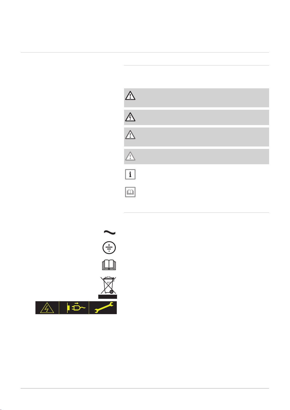
Danger
Risk of dangerous situations that may result in serious personal
injury.
Danger of electric shock
Risk of electric shock.
Warning
Risk of dangerous situations that may result in minor personal
injury.
Caution
Risk of material damage.
Fig.1
Important
Please note: important information.
See
Reference to other manuals or pages in this manual.
2.1.2 Symbols used on the appliance
1 Alternating current.
2 Protective earthing.
3 Before installing and commissioning the appliance, carefully read
the instruction manuals provided.
4 Dispose of used products through an appropriate recovery and
recycling structure.
5 Caution: danger of electric shock, live parts. Disconnect the mains
power prior to carrying out any work.

3 Technical specifications
12 MID _HMI T-control - Gas 120 ACE 7717201 - v03 - 25062019
3 Technical specifications
3.1 Homologations
3.1.1 Standards & Directives
This product complies with the requirements of the following European
directives and standards:
Standards: EN15502
Efficiency Directive 92/42/EC
Low Voltage Directive 2014/35/EU
Generic standard: EN 60335-1
Relevant standard: EN 60335-2-102
Electromagnetic Compatibility Directive 2014/30/EU
Generic standards: EN 61000-6-3, EN 61000-6-1
Relevant Standard: EN 55014
Ecodesign Directive
This product conforms to the requirements of European Directive
2009/125/EC on the ecodesign of energy-related products.
In addition to the legal requirements and guidelines, the supplementary
guidelines in this manual must also be followed.
Supplements or subsequent regulations and guidelines that are valid at
the time of installation shall apply to all regulations and guidelines
specified in this manual.
Warning
The appliance must be installed by a qualified professional in
accordance with applicable local and national regulations.
3.1.2 Factory test
Before leaving the factory, each appliance is tested for the following:
Electrical tests (components, safety).
3.2 Electrical diagram
SCB-02
1
2
3
4 5
BL
YE
RE BK
OR
1
2
3
4 5
BL
YE
RE BK
OR
MW-2000917-01
10 A
L
N
230V/50Hz
BL
G/Y
BR
1
2
3
G/Y
BR
BL
1
2
3
4 5
BL
YE
RE BK
OR
BL
G/Y
BR
BL
G/Y
BR
24V
12 11
BL GR
10 9 8 7 6
OR BK RE YE BL
5 4 3 2 1
OR BK RE YE BL
230V
1 2 3 4 5
G/Y
BR BL
6 7 8 9 10
G/Y
BR BL
WH
BK
RE
YE
BL
GR
OR
BL
YE
RE
BK
OR
CB-09 IF-01
8 9
7
2
3
4
6
5
1
7717201 - v03 - 25062019 MID _HMI T-control - Gas 120 ACE 13
Fig.2
3 Technical specifications
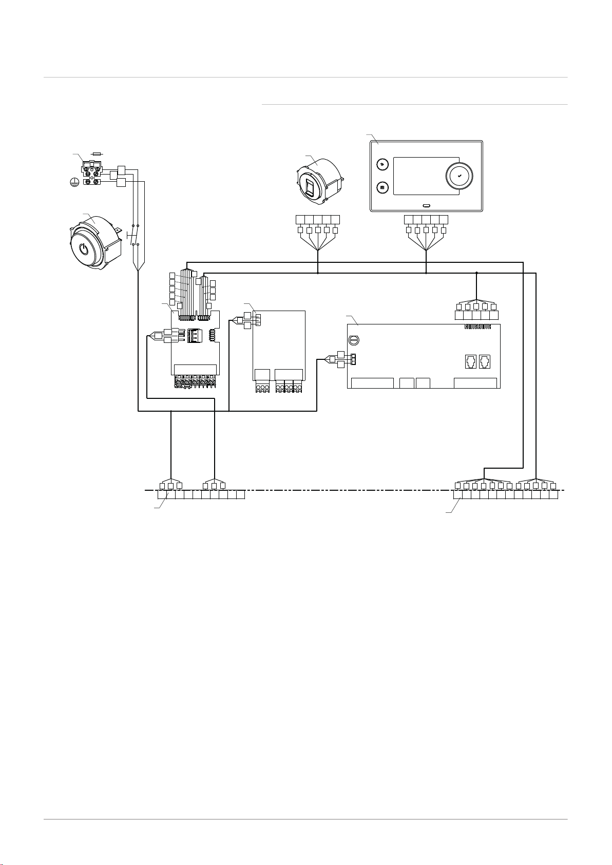
3.2.1 Electrical diagram for the MID control unit HMI T-control
1 MID control panel HMI T-control
2 Service connector, allows the technician to work on
the equipment
3 230 V mains power supply connection with 10 A fuse
4 On/Off switch
5 230 V connector, connection with the boiler
6 24 V connector, connection with the boiler
7 SCB-02 PCB
8 CB-09 PCB
9 IF-01 PCB
BK Black
BL Blue
BR Brown
G/Y Green/Yellow
YE Yellow
OR Orange
GR Green
PI Pink
GY Grey
RD Red
WH White
AD-3001313-01
C No
Nc
Status A
C No
Nc
Status B
N L
+
-
0-10
Tout
N L
N
+
-
0-10
Tdhw Tflow
R-Bus
MW-2000918-01
1
4
3
2
5
7
6
4 Description of the product
14 MID _HMI T-control - Gas 120 ACE 7717201 - v03 - 25062019
4 Description of the product
4.1 General description
The control box is used to control the operation of a Gas 120 ACE boiler.
The box is equipped with a HMI T-control control panel.
4.2
Main components
Fig.3
4.3 PCBs
Fig.4
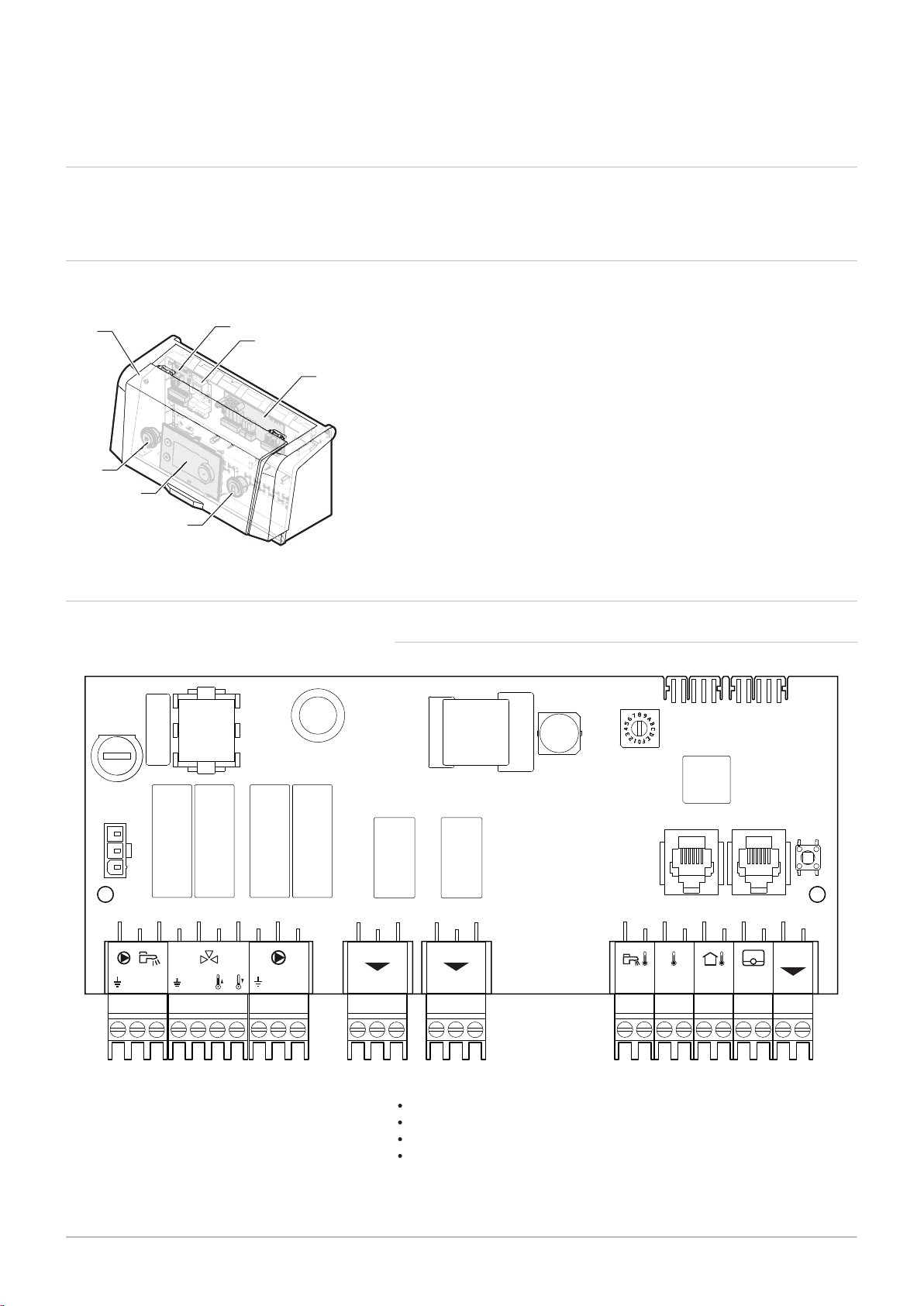
SCB-02 expansion board
1 Protective cover
2 On/Off switch
3 HMI T-control control panel
4 Service connector, allows the technician to work on the equipment
5 SCB-02 PCB
6 IF-01 PCB
7 CB-09 PCB
4.3.1 SCB-02 expansion board description
The expansion board SCB-02 has the following features;
control of a (mixing) zone for heating (or cooling)
control of one domestic hot water (DHW) zone
0–10 V output control for a PWM system pump
two potential-free contacts for status notifications
Important
Tout - +BL RL
LN
R-Bu
s
PWM
1
6
MW-2000826-01
2 3 4 5
AD-0000054-01
Status 0-10 0-10
Nc NoC
Nc No OTm 0 + 0 +C
OTm 0 + 0 +
X5
X4
X1
IF-01
%
1
2
7717201 - v03 - 25062019 MID _HMI T-control - Gas 120 ACE 15
If the boiler is fitted with the SCB-02 board, then this is
automatically recognised by the automatic control unit of the
boiler.
On removing this board, the boiler will show an error code. To
prevent this error, carry out an auto-detect immediately after
removing this board.
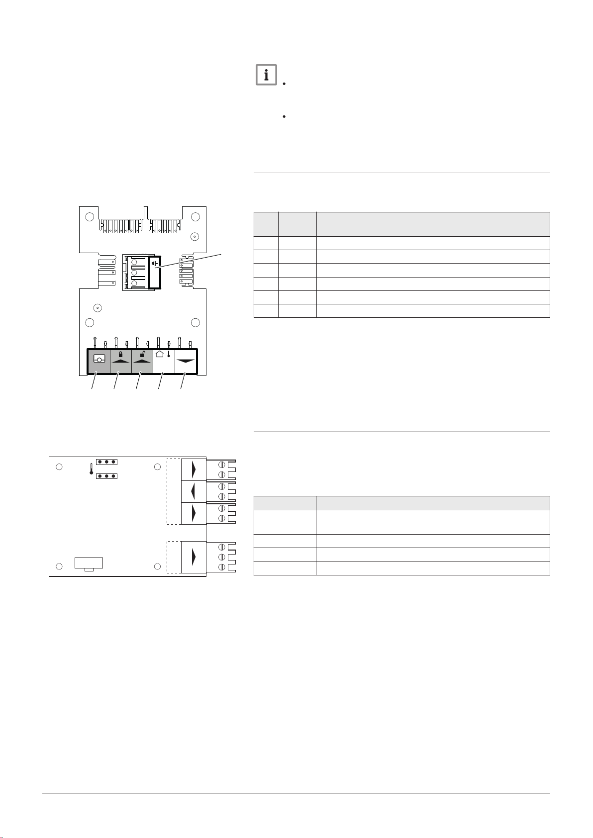
4.3.2 Description of the CB-09 PCB
4 Description of the product
Fig.5
Fig.6
The CB-09 PCB allows additional inputs to be connected as per the
following table:
Mar
ker
Con
nector
Description
1 R-Bus Not used
2 BL Boiler frost protection (active if contact open)
3 RL Release open contact
4 Tout Not used
5 PWM Modulating pump control connection
6 X4 Modulating pump power connection
4.3.3 Description of the IF-01 PCB
The IF-01 PCB is factory fitted and allows additional inputs such as a
sensor or switch to be connected to the system.
This PCB controls the boiler with the 0-10V signal from an external control
system.
Connector Description
0-10 (input) The 0-10V signal corresponds to a temperature or power
set point, depending on the position of the jumpers
0-10 (output) Output signal indicating the boiler's operating mode
Status Boiler fault reporting contact output
OTm Communication link with the CU-GH-08 PCB
Off
MW-5000756-1
3
4
1
2
5
6
29,4°C29,6°C
51,2°C 6,7°C
21,8°C
29,4°C
1,8 bar
Not Set
None o OFF
OK
I
I
MW-5000763-2
2 4 31
4 Description of the product
16 MID _HMI T-control - Gas 120 ACE 7717201 - v03 - 25062019
4.4 Control panel description
Caution
Do not connect a frost thermostat or room thermostat to the boiler
if using the 0–10 V PCB.
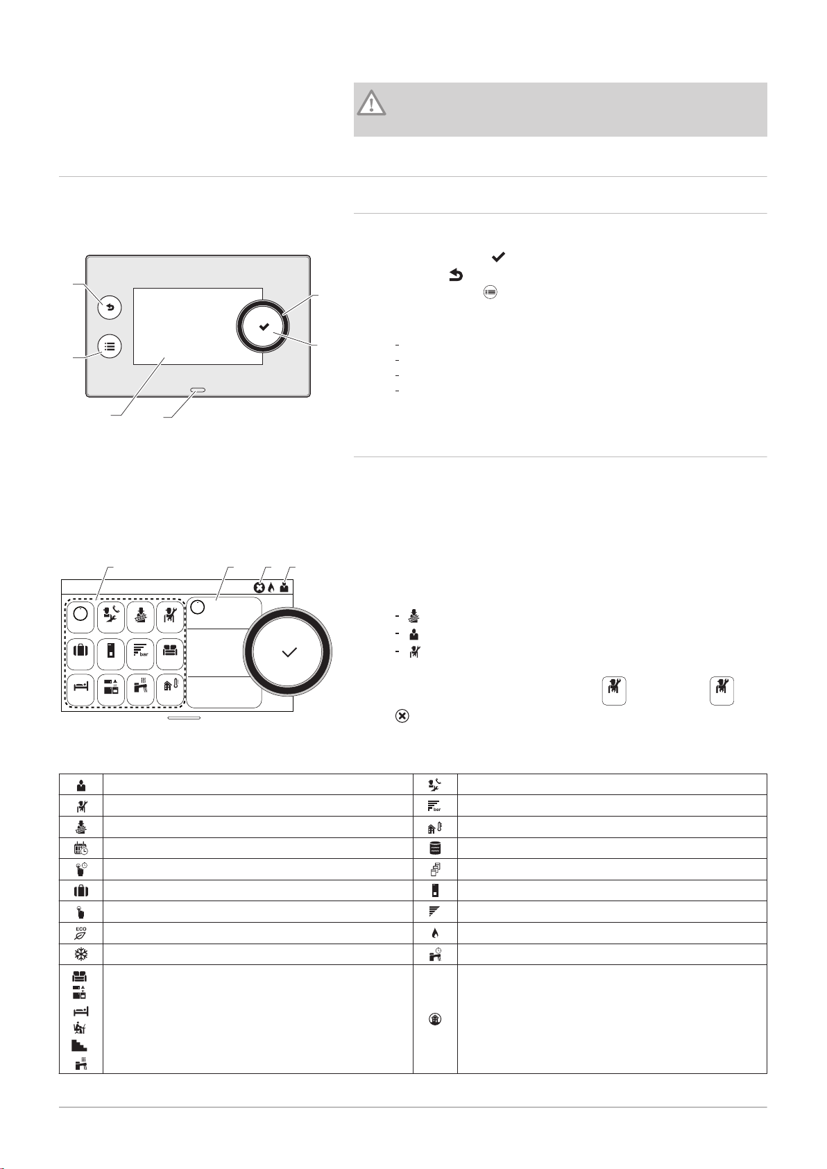
4.4.1 Description of the user interface
Fig.7
Fig.8
1 Rotary knob to select a menu or setting
2
Validation button
3
Back key to return to the previous level or previous menu
4
Main menu key
5 Display screen
6 LED for status indication:
continuous green = normal operation
flashing green = warning
continuous red = shutdown
flashing red = lockout
4.4.2 Description of the main screen
This screen is displayed automatically after the appliance is started up.
The screen goes into standby if no key is pressed for five minutes. Press
one of the buttons on the control panel to exit standby.
1 Symbols
The selected icon is highlighted.
2 Information on the selected icon
3 Navigation level:
: Chimney Sweep level
: User level
: Installer level
This level is reserved for installers and is protected by an access
Tab.1 Symbols
User Level
Installer Level Water pressure
Chimney Sweep level
Timer programme Buffer tank
Timer programme override Cascade
Holiday mode Boiler
Manual mode
Eco mode Burner on
Frost protection mode Domestic hot water override
,
,
Zone icons All zones
,
,
code. When this level is active, the
4
error notification: only visible if an error occurs.
icon becomes On.
Maintenance message
Outdoor temperature sensor
Burner output level

4.5 Standard delivery
7717201 - v03 - 25062019 MID _HMI T-control - Gas 120 ACE 17
4.6 Accessories & options
4 Description of the product
The package contains:
A complete control box for a Gas 120 ACE boiler
Two mounting bolts with two serrated washers
An outdoor temperature sensor
A control box installation, user and service manual
A detailed list of accessories and options can be found in our catalogue.
MW-6000750-02
Manual
1
MW-6000760-01
3
4
2
2
5 Installation
18 MID _HMI T-control - Gas 120 ACE 7717201 - v03 - 25062019
5 Installation
5.1 Installation regulations
Caution
The appliance must be installed and maintained by a certified
professional in accordance with prevailing statutory texts and
codes of practice.
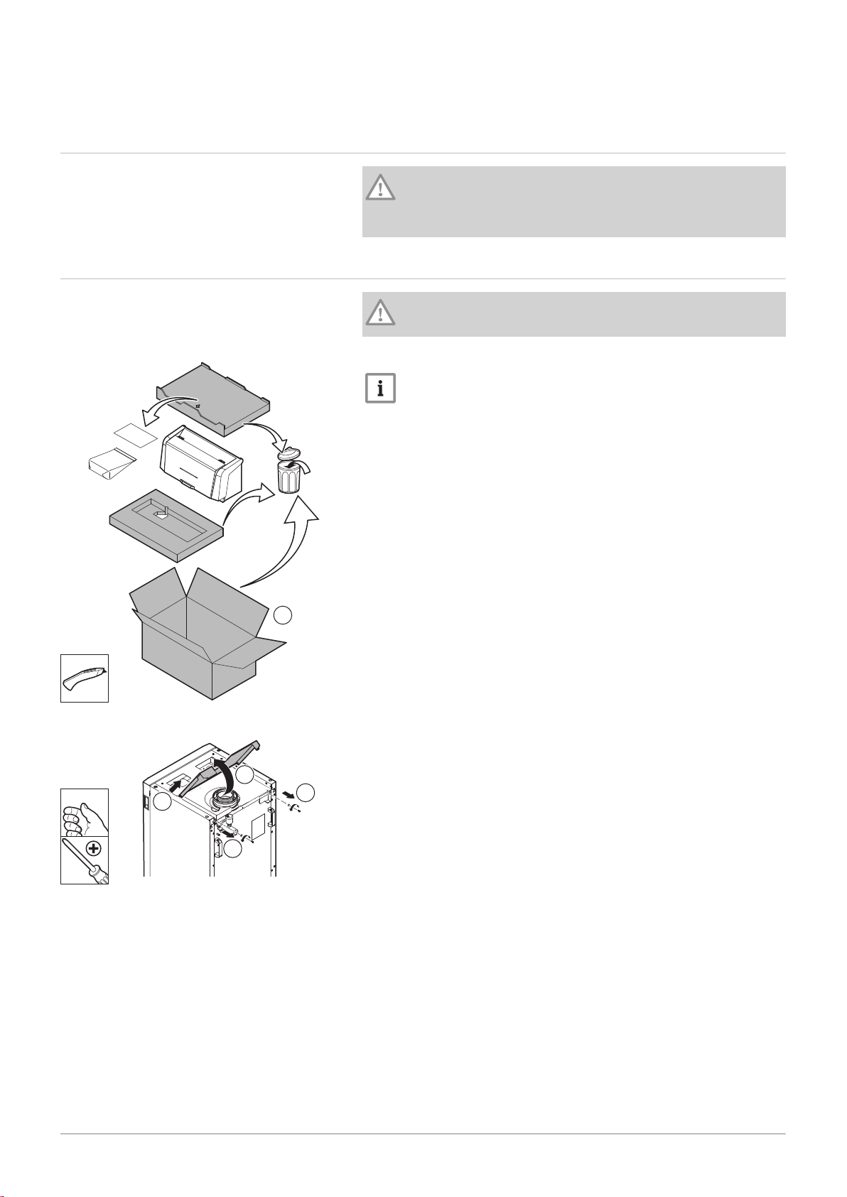
5.2
Fig.9
Unpack and fit the control box
Caution
Wear gloves when handling the control box.
1. Cut and remove the packaging.
Important
The technical documentation is housed in the protective block.
Fig.10
2. Remove the two screws from the boiler's rear top panel.
3. Lift the top panel.
4. Remove the top panel.
MW-2000680-03
5
5
MW-6000762-01
6
6
MW-6000763-02
7
90º
MW-6000764-01
8
5 Installation
7717201 - v03 - 25062019 MID _HMI T-control - Gas 120 ACE 19
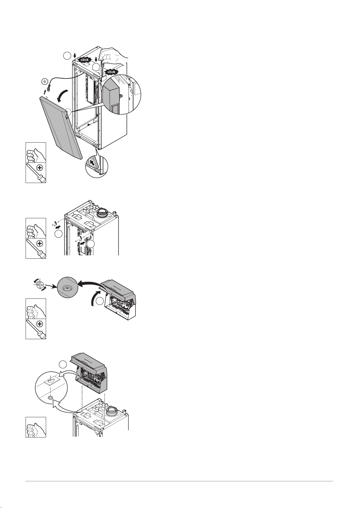
Fig.11
Fig.12
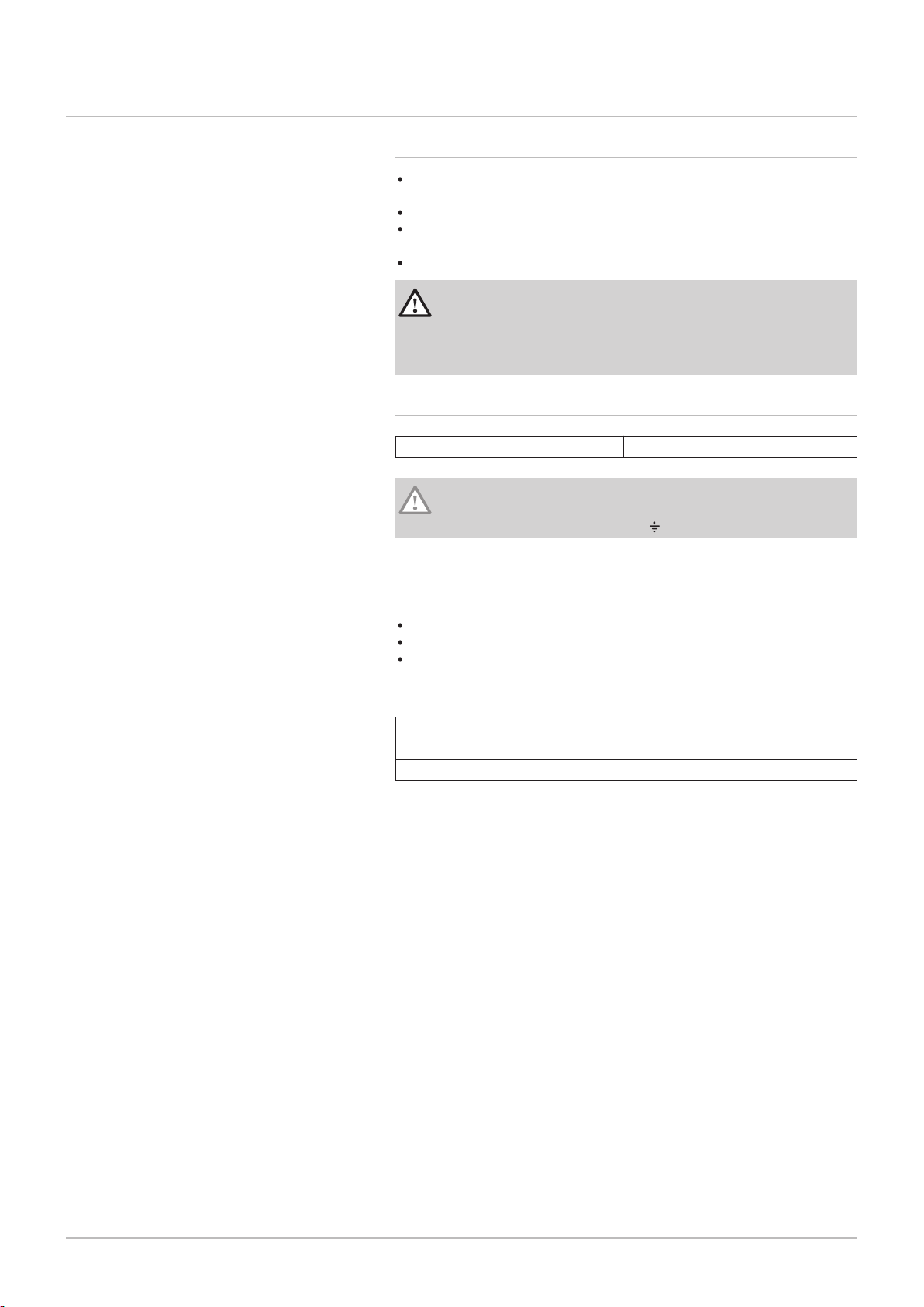
5. Remove the front door.
6. Remove the two retaining screws from the front top panel.
Fig.13
Fig.14
7. Open the control box cover.
8. Align the boiler's tapered interlocks with the notches on the control
box.
MW-6000765-02
9
9
10
MW-6000766-02
230V
24V
11
12
12
MW-6000767-01
13
MW-6000768-02
14
14
15
MW-6000769-01
16
5 Installation
20 MID _HMI T-control - Gas 120 ACE 7717201 - v03 - 25062019
Fig.15
Fig.16
Fig.17
9. Fit the box and slide it forwards.
10. Lock the box using the two screws and toothed washers supplied in
the bag with the manual.
11. Tilt the assembly backwards.
12. Connect the two connectors from the boiler to the connectors on the
control box.
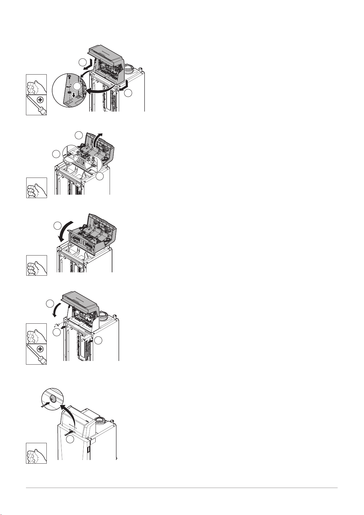
13. Move the control box back to its original position by tilting it forwards.
Fig.18
Fig.19
14. Lock the control box in position using the two screws and the toothed
washers.
15. Close the box cover.
16. Lock the cover by pressing on the screw head.
17. Refit the front door and the rear top panel and refit the two screws and
the toothed washers.
5.3 Electrical connections
7717201 - v03 - 25062019 MID _HMI T-control - Gas 120 ACE 21
5 Installation
5.3.1 Recommendations
Only qualified professionals may carry out electrical connections, always
with the power off.
Earth the appliance before making any electrical connections.
Power the appliance via a circuit that includes an omni-polar switch with
contact opening distance of 3 mm or more.
When making electrical connections to the mains, respect the polarities.
Danger
Position the various electrical cables in such a way that they never
touch the heating pipes.
Keep the various electrical cables far enough from the heating
pipes so that they cannot be damaged by the effect of the heat.
5.3.2 Electrical power supply
Power supply voltage 230 V AC/50 Hz
Caution
Please ensure the polarities shown on the terminals are followed,
i.e live (L), neutral (N) and earth ( )
5.3.3 Recommended cable cross section
Decide on the cable according to the following information:
Distance of the appliance from the power source.
Upstream protection.
Neutral operating conditions.
Tab.2 Specifications of the power cable and the power source
Cable cross section 3 x 1.5 mm²
Curve C (circuit breaker) 10 A
Differential 30 mA
MW-2000830-02
1
2
1
MW-2000831-01
3
MW-2000832-01
4
90º
5 Installation
22 MID _HMI T-control - Gas 120 ACE 7717201 - v03 - 25062019
Caution
Provide a separate power supply for the pump and a power
switch, if necessary.
The output available per outlet is 450 W (2 A, with cos ϕ = 0.7)
and the inrush current must be less that 16 A. If the load exceeds
either of these values, the control must be relayed using a
contactor that must in no circumstances be installed in the control
panel. The sum of the currents from all outlets must not exceed
5 A.
5.3.4 Cable routing and access to the connection terminal
blocks
Fig.20
Fig.21
1. Unlock the front door.
2. Tilt and lift the door to remove it.
3. Remove the two screws and dismantle the rear top panel.
Fig.22
4. Unlock and open the cover on the control box.
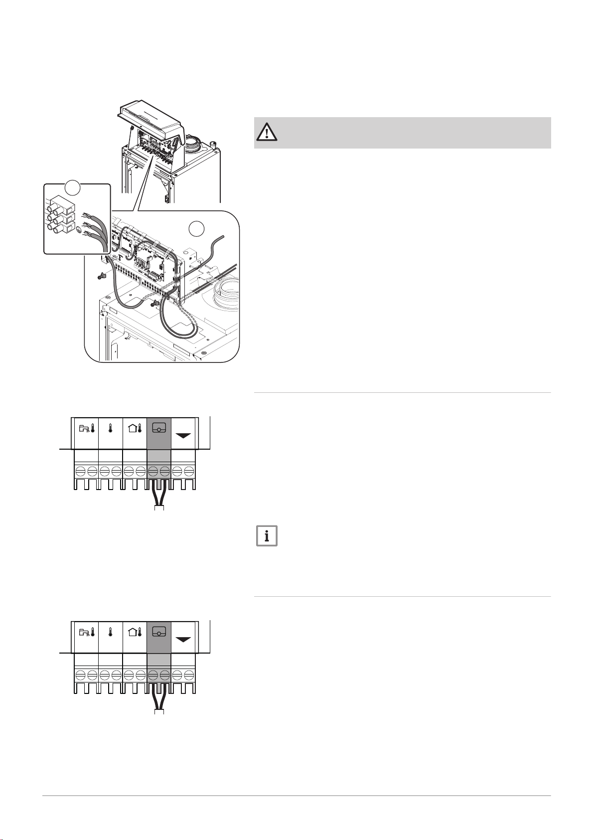
Fig.23
MW-2000833-02
Sensor
230V
5
230V
L
N
6
MW-2000919-01
OT
0-10
Tout
+
-
0-10
Tdhw
Tflow
R-Bus
MW-2000920-01
Tk
0-10
Tout
+
-
0-10
Tdhw
Tflow
R-Bus
7717201 - v03 - 25062019 MID _HMI T-control - Gas 120 ACE 23
5 Installation
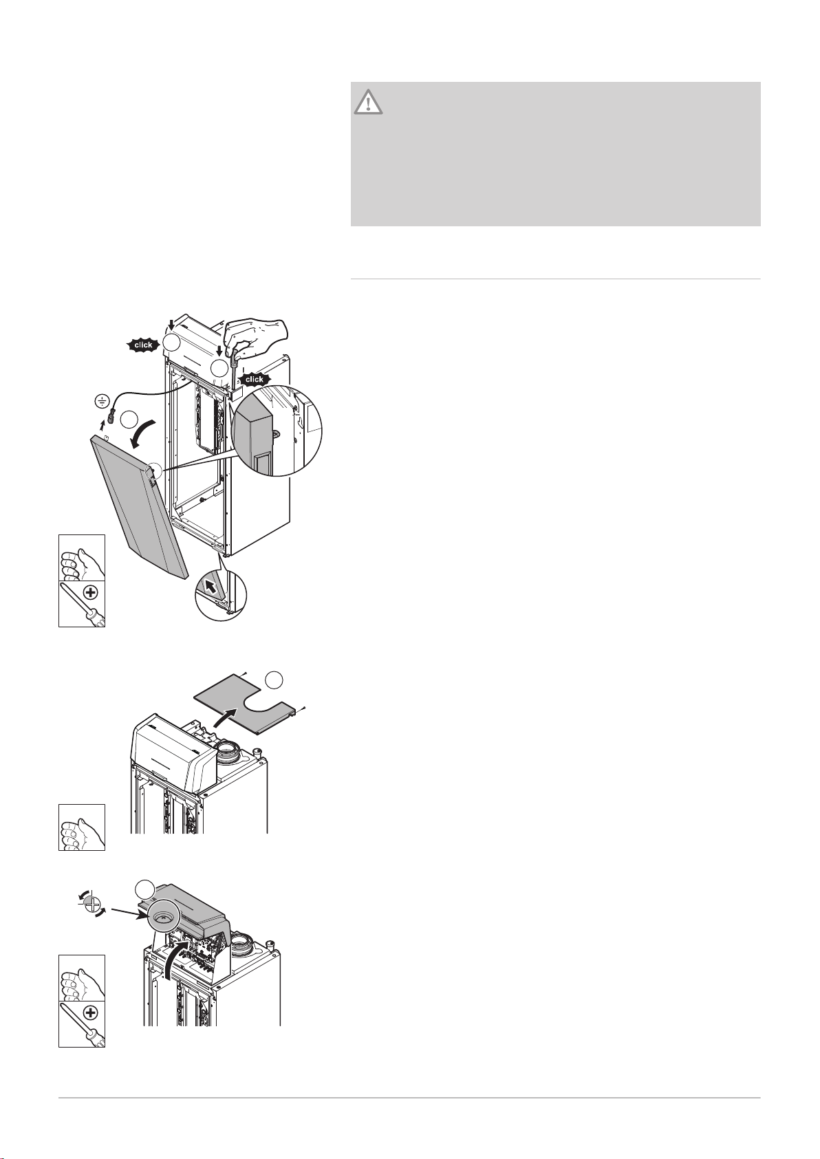
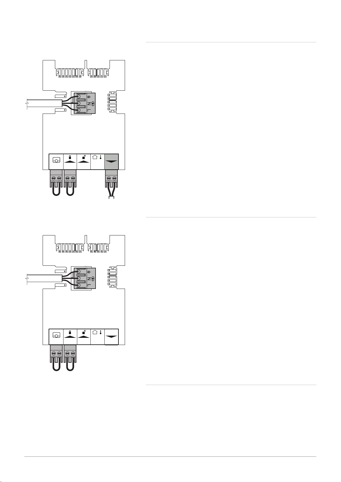
5. Ensure that the cables are correctly routed and affix the cable(s) using
the traction arrester devices.
230 V 230 V circuits (left)
Sensor Sensor circuits (right)
Danger
Separate the sensor cables from the 230 V circuit cables.
6. Connect the boiler's main power supply cable.
Fig.24 to SCB-02
Fig.25 to SCB-02
5.3.5 Connecting a modulating thermostat
The boiler is fitted with an R-Bus connection as standard. This connection
is also compatible with OpenTherm. This enables the user to connect
OpenTherm modulating thermostats (such as iSense Pro) or R-Bus
thermostats (such as eTwist) without any further adjustments being made
to the appliance. The boiler is also suitable for OpenTherm Smart Power.
1. In the case of a room thermostat: install the thermostat in a reference
room.
2. Connect the two-wire cable for the thermostat to the R-Bus terminals
for the connector. It does not matter which wire is connected to which
terminal block.
Important
If the domestic hot water temperature can be set on the
OpenTherm thermostat, the boiler will supply this temperature,
with the value set in the boiler as a maximum.
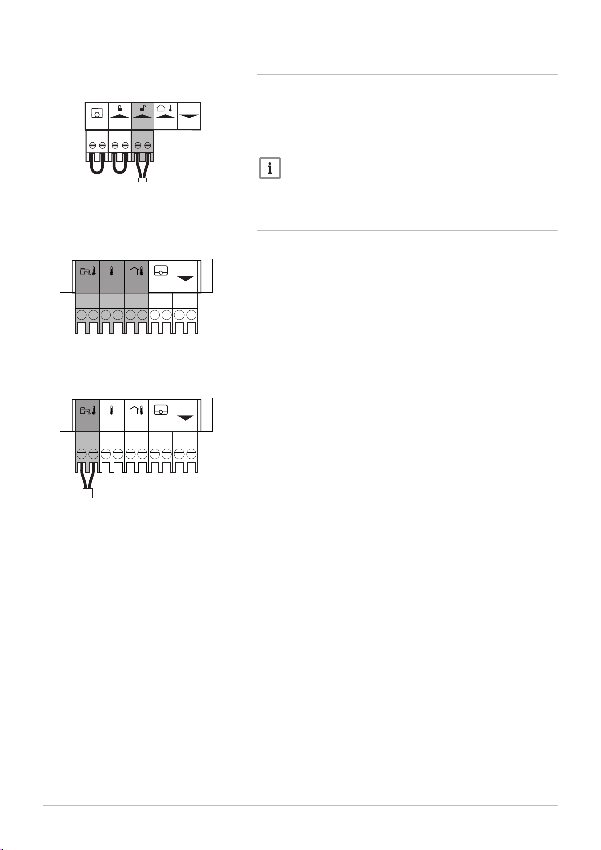
5.3.6 Connecting an on/off thermostat
The boiler is suitable for connection to a two-wire on/off room thermostat
(Tk).
1. Fit the thermostat in a reference room.
2. Connect the two-wire cable for the thermostat to the R-Bus terminals
of the connector. It does not matter which wire is connected to which
terminal block.
MW-2000921-01
TvTk
0-10
Tout
+
-
0-10
Tdhw
Tflow
R-Bus
MW-2000922-01
0-10
Tout
+
-
0-10
Tdhw
Tflow
R-Bus
MW-2000922-01
0-10
Tout
+
-
0-10
Tdhw
Tflow
R-Bus
MW-2000873-01
ToutBL RL
R-Bus
- +
PWM
5 Installation
24 MID _HMI T-control - Gas 120 ACE 7717201 - v03 - 25062019
5.3.7 Frost protection combined with on/off thermostat
Fig.26 to SCB-02
Fig.27 to SCB-02
When an on/off thermostat is used, the pipes and radiators in a frostsensitive room can be protected by a frost thermostat. The radiator valve
in the frost-sensitive room must be open.
1. Place a frost thermostat (Tv) in a frost-sensitive room (e.g. a garage).
2. Connect the frost thermostat (Tv) and the on/off thermostat (Tk) in
parallel to the
R-Bus terminals of the connector.
Warning
If a Remeha eTwist or OpenTherm thermostat is used, a frost
thermostat cannot be connected in parallel to the R-Bus terminals.
In this case, ensure frost protection of the central heating system
in combination with an outside sensor.
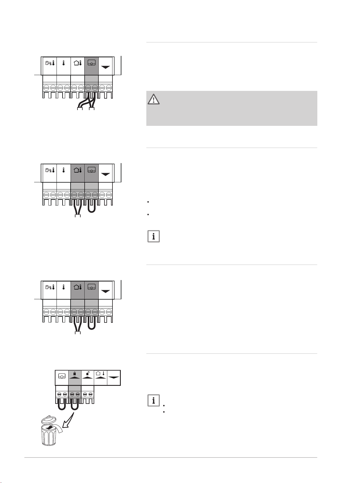
5.3.8 Frost protection combined with outdoor temperature sensor
The central heating system can also be protected against frost in
combination with an outdoor temperature sensor. The radiator valve in the
frost-sensitive room must be open.
1. Connect the outdoor temperature sensor to the Tout terminals of the
connector.
The frost protection works as follows with an outdoor temperature sensor:
If the outdoor temperature is lower than -10 °C: heat demand from the
boiler.
If the outdoor temperature is higher than -10 °C: no heat demand from
the boiler.
Fig.28 to SCB-02
Fig.29 to CB-09
Important
The outdoor temperature before the start of frost protection can be
changed with the AP080 parameter.
5.3.9 Connecting an outdoor temperature sensor
An outdoor temperature sensor (accessory) can be connected to the Tout
terminals of the connector. If the boiler is equipped with an on/off
thermostat, the temperature is controlled using the setpoint of the internal
heating curve (F). Various parameter settings can be used to change the
internal heating curve.
1. Connect the plug from the outdoor temperature sensor to the Tout
terminal.
5.3.10 Blocking input
The boiler has a blocking input (normally closed contact). This input
relates to the BL terminals of the connector.
If this contact is opened, the boiler will be blocked or locked out.
Change the function of the input by configuring the AP001 parameter.
Important
Remove the bridge if this input is used.
Only suitable for potential-free contacts.
5.3.11 Release input
MW-2000874-01
T
out
BL RL
R-Bus
- +
PWM
MW-2000932-01
0-10
Tout
+
-
0-10
Tdhw
Tflow
R-Bus
MW-2000923-01
0-10
Tout
+
-
0-10
Tdhw
Tflow
R-Bus
7717201 - v03 - 25062019 MID _HMI T-control - Gas 120 ACE 25
5 Installation
Fig.30
Fig.31
to CB-09
The boiler has a release input (normally open contact). This input relates
to the RL terminals of the connection terminal block.
If this contact is closed when there is a heat demand, the boiler will be
blocked after a waiting time.
Change the waiting time of the input by configuring the AP008 parameter.
Important
Only suitable for potential-free contacts.
5.3.12 Connecting external sensors
Tdhw
Tflow
The sensor connection contacts are dry contacts.
Tank sensor (NTC 10 k Ohm)
Boiler flow temperature sensor (NTC 10 k Ohm)
Tout
Outdoor temperature sensor (NTC 10 k Ohm)
5.3.13 Connecting a tank sensor or thermostat
Fig.32 to SCB-02
A sensor or thermostat can be connected to the Tdhw terminals of the
connector.
1. Connect the domestic hot water sensor or the tank thermostat to the
Tdhw connector.
MW-2000878-02
Tout - +BL RL
R-Bus
PWM
X4
CB-09
Tout - +BL RL
R-Bus
PWM
CB-09
MW-2000879-02
X4
5 Installation
26 MID _HMI T-control - Gas 120 ACE 7717201 - v03 - 25062019
5.3.14 Connecting a PWM pump
Fig.33
to CB-09
1. Connect the modulating pump to the X4 terminal for the power section
and to the PWM terminal for the control section, respecting the pump
polarity.
5.3.15 Connecting a standard pump
Fig.34 to CB-09
1. Connect the pump to the X4 terminal on the PCB.
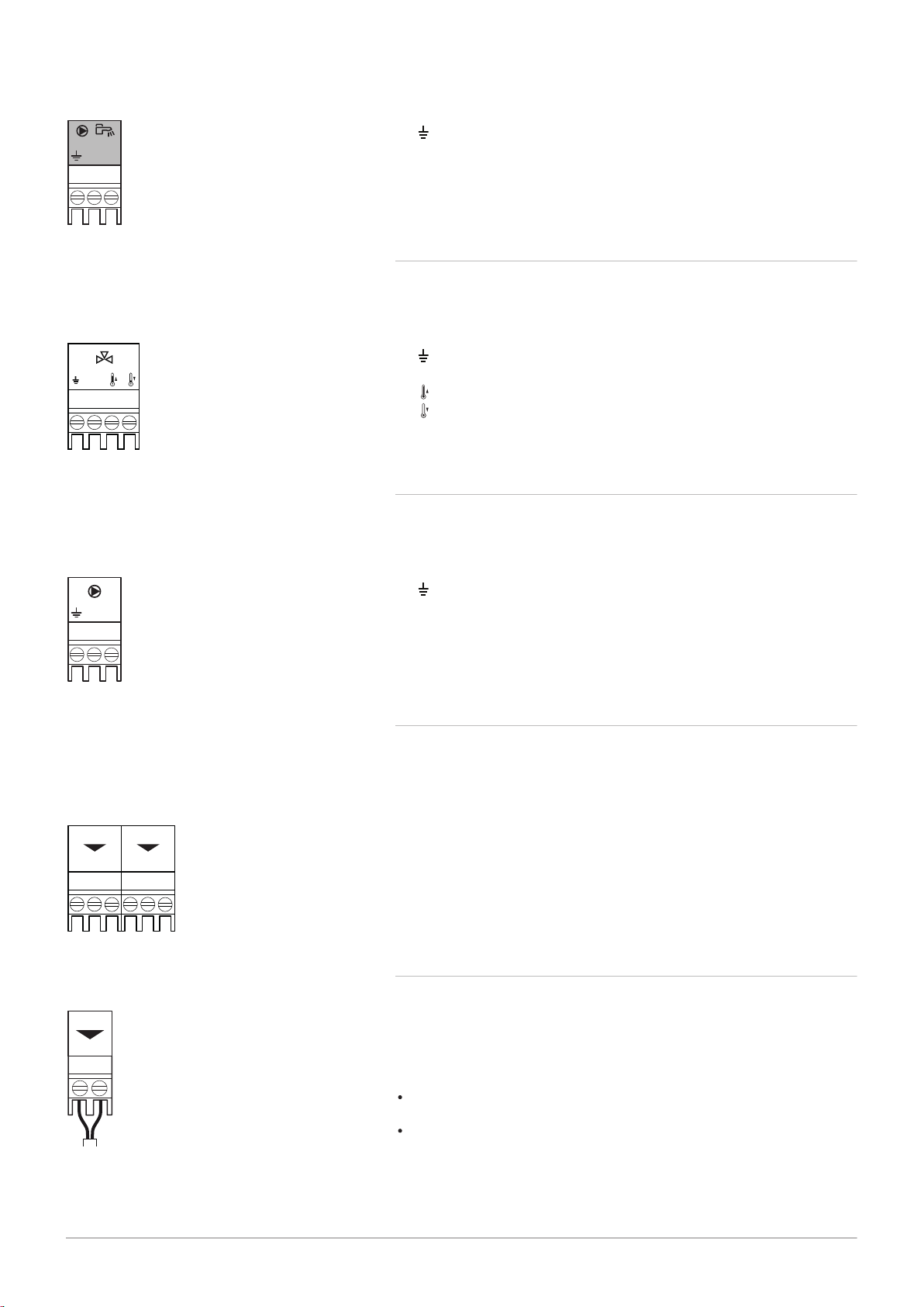
5.3.16
Connecting a domestic hot water (DHW) pump
Connecting a domestic hot water (DHW) pump. The maximum power
consumption is 300 VA.
AD-4000123-01
N L
AD-4000015-02
N
AD-3001306-01
N L
AD-3001312-01
C No
Nc
Status A
C No
Nc
Status B
AD-3001305-01
+
-
0-10
5 Installation
7717201 - v03 - 25062019 MID _HMI T-control - Gas 120 ACE 27
Fig.35
DHW pump connector
Fig.36 Three-way valve connector
Connect the pump as follows:
Earth
N
Neutral
L
Phase
5.3.17 Connecting a three-way valve
Connecting a three-way valve (230 VAC). The connection can be used for
a boiler group (zone).
Connect the three-way valve as follows:
Earth
N
Neutral
Open
Closed
5.3.18
Connecting a system pump for mix group (zone) The maximum power
consumption is 300 VA.
Connecting a system pump for mix group
Fig.37 Pump connector
Fig.38 Status notifications
Fig.39 0–10 V output connector
Connect the pump as follows:
Earth
N
Neutral
L
Phase
5.3.19 Connecting status notifications
The two potential-free contacts, Status, can be configured as required.
Depending on the setting, a particular status can be transmitted by the
boiler.
Connect a relais as follows:
Nc
Normally closed contact. Contact will open when status occurs.
C
Main contact.
No
Normally opened contact. Contact will close when status occurs.
Select the desired status notification (setting) using parameter EP018 and
EP019.
5.3.20 Connecting 0–10 V output
The 0-10 contact can be used to connect a PWM system pump. The
speed of the pump is modulated based on the signal received from the
boiler. Depending on the make and type of pump, the pump can be
controlled by a 0–10 V or a PWM signal.
Connect the system pump controller to connector 0-10.
Select the type of signal that will be sent from the boiler using the
parameter EP029.
Select the type of signal that controls the pump using the parameter
EP028.
AD-0000054-01
Status 0-10 0-10
Nc NoC
Nc No OTm 0 + 0 +C
OTm 0 + 0 +
X5
X4
X1
IF-01
%
1
2
AD-0000055-01
1
2
%
2 2
5 Installation
28 MID _HMI T-control - Gas 120 ACE 7717201 - v03 - 25062019
Caution
If possible, use the pump modulation signal. This provides the
most accurate pump control.
If the automatic burner unit does not support pump modulation,
the pump will behave as an on/off pump.
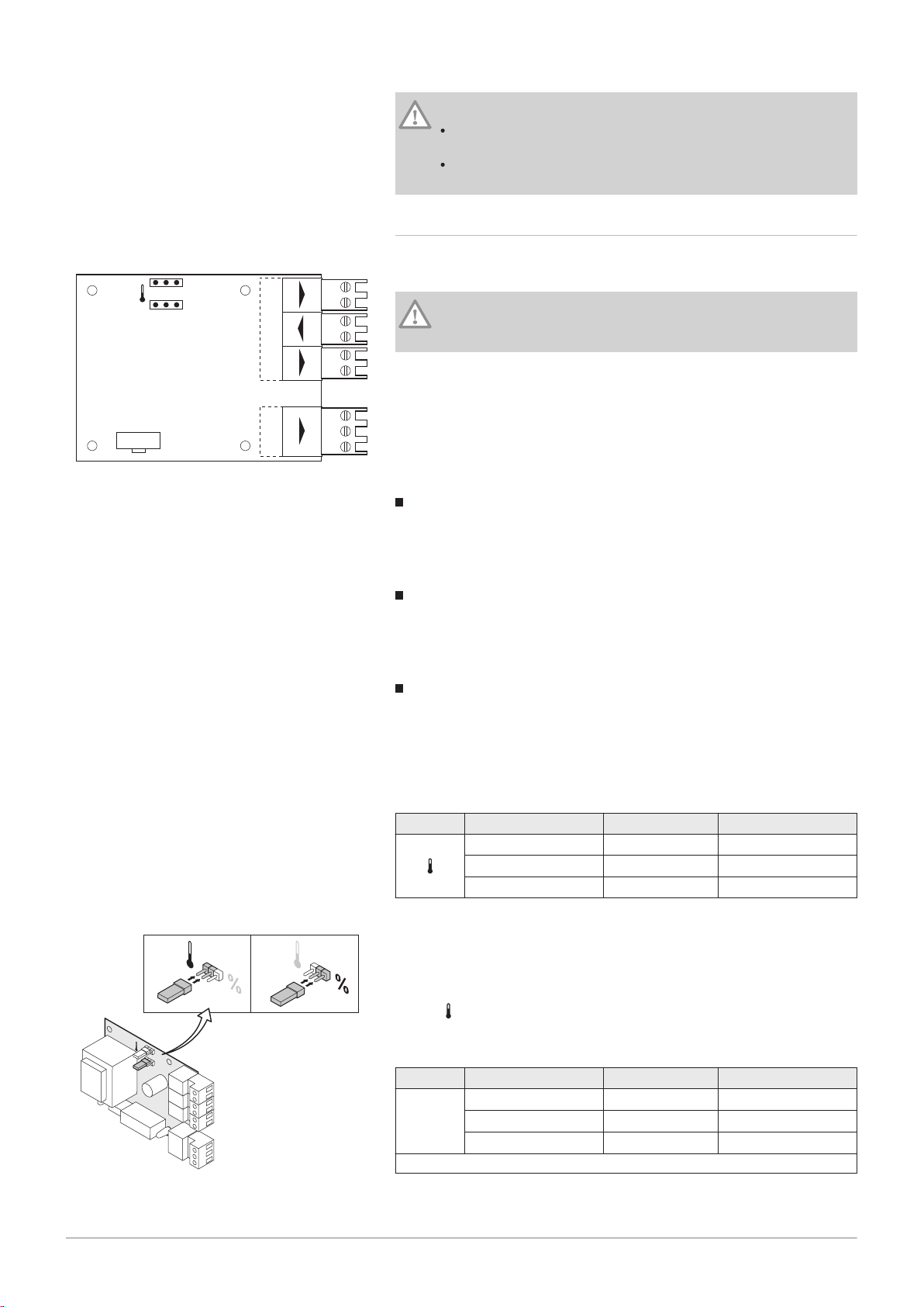
5.3.21 Connection options for the expansion PCB - IF-01
Fig.40 IF-01 PCB
The expansion board IF-01 is pre-installed in the instrument box as
standard.
Caution
Do not connect a frost thermostat or room thermostat to the boiler
if using the 0–10 V control PCB.
Connecting the status relay (Nc)
If the boiler locks out, a relay is de-energised and the alarm can be
transmitted via a potential-free contact (maximum 230 V, 1 A) on terminals
Nc and C of the connector.
Connection (OTm)
The interface uses OpenTherm to communicate with the boiler control
unit. To make this possible, the OTm connection must be connected to the
OpenTherm input of the boiler control unit.OTm
Analogue input (0-10 V)
A choice can be made with this control between control based on
temperature or heat output. The two controls are described briefly below.
1. Connect the input signal to terminals 0–10 of the connector.
Tab.3 Temperature-based control (°C)
Jumper 2 Input signal (V) Temperature °C Description
0–1.5 0–15 Boiler off
1.5–1.8 15–18 Hysteresis
1.8–10 18–100 Desired temperature
Fig.41 Switch jumper (2)
The 0–10 V signal controls the boiler supply temperature. This control
modulates on the basis of flow temperature. The output varies between
the minimum and maximum value on the basis of the flow temperature set
point calculated by the controller.
A jumper (2) on the interface is used to select either temperature-based
control ( ) or output-based control (%).
Tab.4 Control based on heat output
Jumper 2 Input signal (V) Heat output (%) Description
(1)
0–2.0
%
2.0–2.2
2.0–10
(1) Dependent on the minimum modulation depth (set speeds, standard 20%)
(1)
(1)
0–20 Boiler off
20–22 Hysteresis
20–100 Desired heat output
AD-0000056-01
1
2
%
1 1
AD-0001177-01
3
4
5
1
2
5 Installation
7717201 - v03 - 25062019 MID _HMI T-control - Gas 120 ACE 29
The 0–10 V signal controls the boiler output. This control modulates on the
basis of the heat output. The minimum output is linked to the boiler's
modulation depth. The output varies between the minimum and maximum
value on the basis of the value defined by the controller.
Analogue output (0–10 V)
Fig.42
Switch jumper (1)
Fig.43 Connecting an interface connector
This feedback can be based on temperature or heat output. The two
controls are described briefly below.
A jumper (1) on the interface is used to select either temperature ( ) or
output (%).
Tab.5 Temperature message
Jumper 1 Output signal (V) Temperature °C Description
0.5 – Alarm
1–10 10–100 Supplied tempera
ture
Tab.6 Output message
Jumper 2 Output signal (V) Heat output (%) Description
0 0–15 Boiler off
0.5 15–20 Alarm
%
(1)
2.0–10
(1) Dependent on the minimum modulation depth (set speeds, standard 20%)
20–100 Supplied heat output
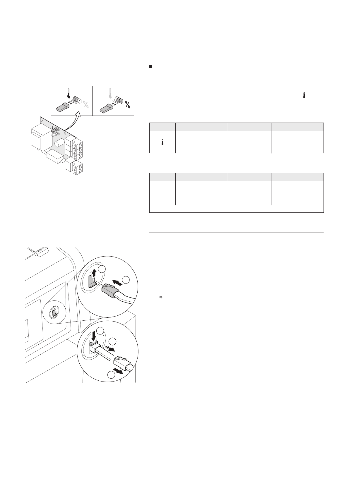
5.3.22 Connecting a PC/laptop
There is a Service connector next to the control panel. A Recom interface
can be used to connect a PC, laptop or a Smart Service Tool here. Using
the Recom PC/laptop service software, you can enter, change and read
out various boiler settings.
Connecting an interface connector:
1. Move the Service connector slide upwards.
2. Push the interface connector into place. It should snap shut with a
click.
Disconnect the interface connector again:
3. Maintain slight tension on the interface connector
4. Push the slide downwards. The interface connector will now be
released.
5. Pull the interface connector from the connector.

AD-4100036-01
1
A
3
2
4
B
5
C
6
AD-4100058-02
C No
Nc
Status A
C No
Nc
Status B
N L
+
-
0-10
Tout
N L
N
+
-
0-10
Tdhw Tflow
R-Bus
1263
4
5
6 Connecting diagrams and configuration
30 MID _HMI T-control - Gas 120 ACE 7717201 - v03 - 25062019
6 Connecting diagrams and configuration
6.1 Factory settings for circuits
In the factory, the different circuits are configured as indicated in the table.
You can modify this configuration and adapt it to the needs of your
installation using the installation type described here as a guide.
Tab.7
Circuit Circuit type Specifications
CIRCA Direct heating circuit Gradient: 1.5
Maximum temperature: 90 °C
DHW Domestic hot water circuit Set point temperature: 55 °C
6.2
Fig.44
Connection example - SCB-02
1 boiler + 1 mixing zone + domestic hot water (DHW) zone
A
Boiler
B
Mixing zone
C
Domestic hot water (DHW) zone (1 sensor)

6 Connecting diagrams and configuration
7717201 - v03 - 25062019 MID _HMI T-control - Gas 120 ACE 31
Important
All the factory settings of the SCB-02 are adequate for this
connection.

7 Commissioning
32 MID _HMI T-control - Gas 120 ACE 7717201 - v03 - 25062019
7 Commissioning
7.1 General
7.2 Check-list before commissioning
Commissioning the boiler is done for first time use, after a prolonged shutdown (more than 28 days) or after any event that would require complete
re-installation of the boiler. Commissioning of the boiler allows the user to
review the various settings and checks to be made to start up the boiler in
complete safety.
1. Check that the gas type supplied matches the data shown on the
boiler's data plate.
Do not commission the boiler if the gas supplied does not match the
gas types approved for the boiler.
2. Check connection of the earth wires.
3. Check the tightness of the gas circuit from the non-return valve to the
burner.
4. Check the hydraulic circuit from the boiler's isolation valves to the
connection to the heating body.
5. Check the hydraulic pressure in the heating system.
6. Check the electricity supply connections to the various boiler
components.
7. Check the electrical connections on the thermostat and the other
external components.
8. Check the ventilation in the room in which the system is installed.
9. Check the flue gas connections.
7.3 Checking the gas inlet
Danger
Ensure that the boiler is switched off.
1. Open the main gas valve.
2. Open the front panel.
3. Check the gas supply pressure at the pressure outlet on the gas valve
unit.
4. Check the tightness of the gas connections made after the gas valve
unit in the boiler.
5. Check the tightness of the gas pipe, including any valves, from the
non-return valve to the burner. The test pressure must not exceed 60
bar (0.006 MPa).
6. Vent the gas supply pipe by unscrewing the pressure outlet on the gas
valve unit. Close the outlet again when the pipe has been sufficiently
vented.
7. Check the tightness of the gas connections in the boiler.

7.3.1 Setting the pressure in the gas circuit
AD-0000066-02
C C
1 2
7717201 - v03 - 25062019 MID _HMI T-control - Gas 120 ACE 33
7 Commissioning
Fig.45
Tab.8
Gas 120 ACE Gas 120 ACE - 65Gas 120 ACE - 90Gas 120 ACE -
Gas inlet pressure G20 (H gas) min–max mbar 17 - 25 17 - 25 17 - 25
G30/G31 gas inlet pressure (Butane/Propane) min–max mbar 37 - 50 37 - 50 37 - 50
G31 gas inlet pressure (Propane) min–max mbar 37 - 50 37 - 50 37 - 50
1 Gas valve -
Gas 120 ACE - 65
Gas 120 ACE - 90
2 Gas valve -
Gas 120 ACE - 115
Warning
Ensure that the boiler is switched off.
Do not commission the boiler if the type of gas supplied does
not match the gas types approved for the boiler.
1. Open the main gas valve.
2. Remove the boiler's front panel.
3. Check the gas inlet pressure at the measuring point C on the gas
valve unit.
The gas pressure that was measured at the measuring point C must
fall within the stated gas inlet pressure limits.
115
7.4 Checking the electrical connections
7.5
Checking the hydraulic circuit
4. Vent the gas supply pipe by unscrewing the measuring point on the
gas valve unit.
5. Tighten the pressure socket again when the pipe has been fully
vented.
6. Check all connections for gas tightness. The maximum allowable test
pressure is 60 mbar (0.006 MPa).
1. Check for the presence of the recommended circuit breaker.
2. Check the electrical connection to the mains.
3. Check the connection of the sensors.
4. Check the position of the sensors. Respect the distance of the
sensors according to the power.
5. Check the connection of the circulating pump(s).
6. Check the connection of the optional equipment.
7. Check the length of the cables and that they are firmly secured in the
cable clamps.
1. Check the siphon, which must be completely filled with water.
2. Check that there are no leaks on the boiler's hydraulic connections.
3. Check the pressure in the expansion vessel before filling the system.

AD-0000067-02
A A
1 2
7 Commissioning
34 MID _HMI T-control - Gas 120 ACE 7717201 - v03 - 25062019
7.6 Starting and stopping the boiler
7.6.1 Commissioning
Caution
Initial commissioning must be done by a qualified professional.
If adapting to another type of gas, e.g. propane, the boiler must
be adjusted before it is switched on.
1. Open the main gas valve.
2. Switch the power on with the boiler's on/off switch.
The boiler starts before the control panel display is active.
3. Set the following parameters when the appliance is first switched on:
Select Country and Language
Configure the date and time used by the appliance
Enable Daylight Saving Time
CN1 and CN2 (codes present on the boiler data plate).
4. Set the components (thermostats, control system) so that they request
heat.
5. Check the hydraulic pressure in the installation shown on the control
panel display.
Recommended hydraulic pressure between 0.15 and 0.2 MPa (1.5
and 2.0 bar).
7.7 Gas settings
Fig.46
Important
In the event of an error during start-up, a message with the
corresponding code is displayed. The meaning of the error codes
can be found in the error table.
7.6.2 Shutting down the boiler
The boiler must be shut down in order for certain operations to be carried
out on the equipment or its environment.
In other situations, such as an extended absence period we recommend
that Holiday Mode mode is used in order to benefit from the heating pump
anti-blocking function and to protect the installation from frost.
To shut down the boiler:
1. Press the on/off switch.
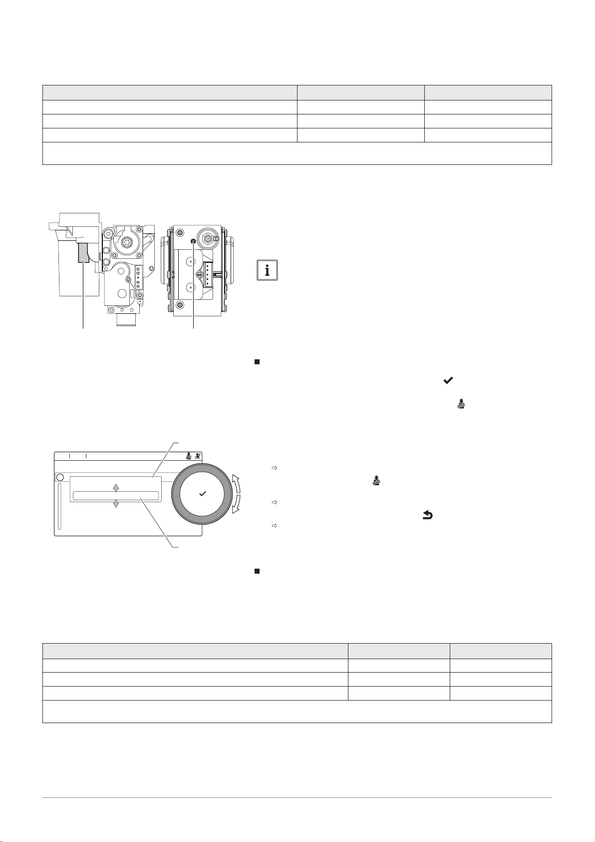
7.7.1 Adapting/adjusting the boiler to different types of gas
1 Gas valve unit on the
Gas 120 ACE - 65
Gas 120 ACE - 90
2 Gas valve unit on the
Gas 120 ACE - 115
Warning
Only a qualified engineer may carry out the following operations.
The boiler is pre-set in the factory to run on G20 type natural gas (H gas).
Before operating with a different type of gas, carry out the following steps:

7 Commissioning
7717201 - v03 - 25062019 MID _HMI T-control - Gas 120 ACE 35
Tab.9 If operating on propane
Type of boiler Action
Gas 120 ACE - 65 Rotate the setting screw A on the venturi 6½ turns in a clockwise direction
Gas 120 ACE - 90 Rotate the setting screw A on the venturi 6½ turns in a clockwise direction
Replace the current gas valve unit with the propane gas valve unit according to the instruc
tions supplied with the propane conversion kit
Gas 120 ACE - 115 Rotate the setting screw A in a clockwise direction until it is closed, then:
Rotate the setting screw A on the gas valve unit 3½–4 turns in an anticlockwise direction
1. Set the fan speed as indicated in the table (if necessary). The setting
can be changed with a parameter setting.
Tab.10 Factory settings G20 (H gas)
Code Parameter Description Adjustment range Gas
120
ACE -
65
DP003 Abs. max fan DHW Maximum fan speed on Domestic
1000 Rpm 7000 Rpm 5600 6300 6800
Gas
120
ACE -
90
ACE -
Hot Water
GP007 Fan RPM Max CH Maximum fan speed during Central
1400 Rpm 7000 Rpm 5600 6300 6800
Heating mode
GP008 Fan RPM Min Minimum fan speed during Central
1400 Rpm 4000 Rpm 1600 1600 1750
Heating + Domestic Hot Water
mode
GP009 Fan RPM Start Fan speed at appliance start 1000 Rpm 4000 Rpm 2500 2500 2500
Gas
120
115
Tab.11 Setting for gas type G30/G31 (butane/propane)
Code Parameter Description Adjustment range Gas
120
ACE -
65
DP003 Abs. max fan DHW Maximum fan speed on Domestic
1000 Rpm 7000 Rpm 5300 5800 6500
Gas
120
ACE -
90
ACE -
Hot Water
GP007 Fan RPM Max CH Maximum fan speed during Central
1400 Rpm 7000 Rpm 5300 5800 6500
Heating mode
GP008 Fan RPM Min Minimum fan speed during Central
1400 Rpm 4000 Rpm 1600 1600 1800
Heating + Domestic Hot Water
mode
GP009 Fan RPM Start Fan speed at appliance start 1000 Rpm 4000 Rpm 2500 2500 2500
Tab.12 Setting for gas type G31 (propane)
Code Parameter Description Adjustment range Gas
120
ACE -
65
DP003 Abs. max fan DHW Maximum fan speed on Domestic
1000 Rpm 7000 Rpm 5400 6000 6700
Gas
120
ACE -
90
ACE -
Hot Water
GP007 Fan RPM Max CH Maximum fan speed during Central
1400 Rpm 7000 Rpm 5400 6000 6700
Heating mode
GP008 Fan RPM Min Minimum fan speed during Central
1400 Rpm 4000 Rpm 1600 2000 1800
Heating + Domestic Hot Water
mode
GP009 Fan RPM Start Fan speed at appliance start 1000 Rpm 4000 Rpm 2500 2500 3500
Gas
120
115
Gas
120
115
2. Check the setting of the gas/air ratio.

MW-2000722-3
AD-3000941-03
..... ... ....... .... .. ..... ....
.........
..... ... ....... ....
..... ... ....... ....
....... .... .. ..... .... .......
....... ...........
......
.....
...
.....
..... ... ....... .... .. ..... ....... .... ..... .......
i
.....
....... .... ....... .... .......
.... ...... ....... ......11:20
A
B
7 Commissioning
36 MID _HMI T-control - Gas 120 ACE 7717201 - v03 - 25062019
7.7.2 Checking/adjusting the combustion
Fig.47
Fig.48 Full load test
1. Unscrew the cap from the flue gas measuring point.
2. Insert the probe for the flue gas analyser into the measurement
opening.
Important
During measurement, seal the opening around the sensor fully.
The flue gas analyser must have a minimum accuracy of
±0.25% O2/CO2.
3. Measure the percentage of O2/CO2 in the flue gases. Take
measurements at full load and at part load.
Performing the full load test
1. Select the tile [ ].
The Change load test mode menu appears.
2. Select the test MaximumPowerCH.
A
Change load test mode
B MaximumPowerCH
The full load test starts. The selected load test mode is shown in the
menu and the icon
3. Check the load test settings and adjust if necessary.
Only the parameters shown in bold can be changed.
appears in the top right of the screen.
Tab.13
Values at full load for G20 (H gas)
Gas 120 ACE - 65
Gas 120 ACE - 90
Gas 120 ACE - 115
(1) nominal value
(2) Values given as a guide
Tab.14
Values at full load for G31 (propane)
Gas 120 ACE - 65
Gas 120 ACE - 90
Gas 120 ACE - 115
(1) nominal value
(2) Values given as a guide
Control and setting values for O2 at full load
1. Set the boiler to full load.
2. Measure the percentage of O2 in the flue gases.
3. Compare the measured value with the set point values in the tables.
O2 %
4.3 - 4.8
4.3 - 4.7
4.2 - 4.7
O2 %
4.6 - 4.9
4.9 - 5.2
4.9 - 5.4
(1)
(1)
(1)
(1)
(1)
(1)
(1)
(1)
10.5
10.3
10.2
CO2 %
(1)
9.0
(1)
9.1
(1)
9.1
CO2 %
(1)
(1)
(1)
(1)(2)
- 9.3
- 9.3
- 9.4
(1)(2)
- 10.7
- 10.5
- 10.5
Tab.15
MW-2000724-1
A A
AD-3000941-03
..... ... ....... .... .. ..... ....
.........
..... ... ....... ....
..... ... ....... ....
....... .... .. ..... .... .......
....... ...........
......
.....
...
.....
..... ... ....... .... .. ..... ....... .... ..... .......
i
.....
....... .... ....... .... .......
.... ...... ....... ......11:20
A
B
7717201 - v03 - 25062019 MID _HMI T-control - Gas 120 ACE 37
Values at full load for G30/G31 (butane/propane)
Gas 120 ACE - 65
Gas 120 ACE - 90
Gas 120 ACE - 115
(1) nominal value
(2) Values given as a guide
Fig.49
7 Commissioning
O2 %
4.9 - 5.4
4.9 - 5.4
4.9 - 5.4
(1)
(1)
(1)
(1)
10.2
10.2
10.2
CO2 %
(1)
(1)
(1)
(1)(2)
- 10.5
- 10.5
- 10.5
4. If the measured value differs from that given in the table, correct the
gas/air ratio.
5. Using the setting screw A, set the percentage of O2 for the gas type
being used to the nominal value. This should always be within the
highest and lowest setting limits.
Allow the pressure to stabilise for approximately 60 seconds between
each setting modification.
Important
The boilers are supplied with a variety of gas valve units.
Compare the gas valve unit in the boiler with those in the drawings
and see the drawing for the position of adjusting screw A for full
load.
Fig.50 Part load test
Tab.16
Values at part load for G20 (H gas)
(1) nominal value
(2) Values given as a guide
Performing the part load test
1. If the full load test is still running, press the button to change the
load test mode.
2. If the full load test was finished, select the tile [ ] to restart the
chimney sweep menu.
A
Change load test mode
B MinimumPower
3. Select the MinimumPower test in the menu Change load test mode.
The part load test starts. The selected load test mode is shown in
the menu and the icon
appears in the top right of the screen.
4. Check the load test settings and adjust if necessary.
Only the parameters shown in bold can be changed.
5. End the part load test by pressing the button.
The message Running load test(s) stopped! is displayed.
Control and setting values for O2 at part load
1. Set the boiler to part load.
2. Measure the percentage of O2 in the flue gases.
3. Compare the measured value with the set point values in the tables.
(1)
O2 %
Gas 120 ACE - 65
Gas 120 ACE - 90
Gas 120 ACE - 115
(1)
4.8
- 5.3 8.7 - 9.0
(1)
4.8
- 5.2 8.8 - 9.0
(1)
5.6
- 6.1 8.3 - 8.6
CO2 %
(1)(2)
(1)
(1)
(1)

MW-2000725-1
B B
B
Off
7 Commissioning
38 MID _HMI T-control - Gas 120 ACE 7717201 - v03 - 25062019
Tab.17
Values at part load for G31 (propane)
Gas 120 ACE - 65
Gas 120 ACE - 90
Gas 120 ACE - 115
(1) nominal value
(2) Values given as a guide
Tab.18
Values at part load for G30/G31 (butane/propane)
Gas 120 ACE - 65
Gas 120 ACE - 90
Gas 120 ACE - 115
(1) nominal value
(2) Values given as a guide
Fig.51
(1)
O2 %
(1)
5.4
- 5.7 10.0 - 10.2
(1)
5.5
- 5.8 9.9 - 10.1
(1)
5.8
- 6.3 9.6 - 9.9
(1)
O2 %
(1)
5.7
- 6.2 9.7 - 10.0
(1)
5.7
- 6.2 9.7 - 10.0
(1)
5.7
- 6.2 9.7 - 10.0
CO2 %
CO2 %
(1)(2)
(1)
(1)
(1)
(1)(2)
(1)
(1)
(1)
The O2 values at low load must be higher than the values at full
load.
4. If the measured value is outside of the values given in the table,
correct the gas/air ratio.
5. Using the adjusting screw B, set the percentage of O2 for the gas type
being used to the nominal value. This should always be within the
highest and lowest setting limits.
Allow the pressure to stabilise for approximately 60 seconds between
each setting modification.
7.8
7.9
Important
The boilers are supplied with a variety of gas valve units.
Compare the gas valve unit in the boiler with those in the drawings
and see the drawing for the position of adjusting screw A for full
load.
6. Repeat the high speed test and the low speed test as often as
necessary until the correct values are obtained without having to
make additional adjustments.
7. Set the boiler back to the normal operating status.
Displaying the water pressure on the control panel
1. Highlight the Water Pressure icon.
The pressure is displayed on the main screen of the control panel.
Modifying the ΔT value
In systems with several operating temperatures, the boiler's ΔT value must
be increased.

Tab.19 Standard ΔT values
7717201 - v03 - 25062019 MID _HMI T-control - Gas 120 ACE 39
Boiler model Standard ΔT Max. ΔT
Gas 120 ACE - 65 25 K 40 K
Gas 120 ACE - 90 25 K 40 K
Gas 120 ACE - 115 20 K 35 K
Increase the ΔT value using the GP021 parameter. When increasing the
ΔT, the control unit limits the linear flow temperature to 80 °C maximum.
This does not modify the value set for the maximum flow temperature. This
value can be adjusted using the CP000 parameter.
Important
If the heat demand is greater than 80 °C with the increased ΔT
value, Recom (or the service tool) will use a sub-status to
indicate that the limited flow temperature is active.
Always ensure that circulation is minimal (using a bypass or
low-loss header if necessary) to prevent the boiler from locking
out.
If a PWM-controlled central heating pump is controlled by the
boiler control panel, set the PP014 parameter to 2.
7 Commissioning
7.10
Points to check after commissioning
1. Remove the measuring equipment.
2. Put the flue gas sampling plug back in place.
3. Put the front casing back.
4. Bring the heating system temperature up to approximately 50°C.
5. Shut down the boiler.
6. After about 10 minutes, vent the air in the heating system.
7. Check that there are no leaks (hydraulic circuit, gas circuit, etc.).
8. Check that the boiler equipment is operating correctly.
9. Check that the thermostats are operating correctly and have the
correct settings.
10. Check the water pressure. Recommended pressure: between 0.15
and 0.2 MPa (1.5 and 2.0 bar).
11. Tidy away or scrap the various packaging items.
12. If necessary, affix the second type plate provided with the
documentation to a visible part of the boiler.
13. Affix the data plate supplied with the control box beside the boiler type
plate.
14. Instruct the user in the operation of the system, boiler and controller.
15. Inform the user of the periodicity of maintenance work to be carried
out.
16. Hand over all manuals to the user.
Commissioning of the boiler is now complete.

1
2
1
2
3
4
5
1
MW-1001145-2
2
MW-1001144-2
°C
16
06:30 09:00 17:00 20:00 23:00
19
20
22
5
1
2
3
4
5
8 Operation
40 MID _HMI T-control - Gas 120 ACE 7717201 - v03 - 25062019
8 Operation
8.1 Definition of zone and activity
8.1.1 Zone
Fig.52
Fig.53
Term given to the different hydraulic circuits CIRCA, CIRCB, .... It
indicates several rooms served by the same circuit.
Tab.20 Example
Marker Zone Factory-set name
Zone 1 CIRCA
Zone 2 CIRCB
8.1.2 Activity
This term is used when programming time ranges. It refers to the client's
desired comfort level for different activities during the course of the day.
One set point temperature is associated to each activity. The last activity
of the day remains valid until the first activity of the following day.
Tab.21 Example:
Start
of the activity
6:30
9:00
17:00
20:00
23:00
Activity Set point temperature
Morning
Away
Home
Evening
Sleep
20 °C
19 °C
20 °C
22 °C
16 °C
8.2 Switching the summer mode on or off
You can switch off the central heating function of the boiler to save energy,
for example during the summer period.
1. Select the tile [ ].
2. Press the button to confirm the selection.
3. Use the rotary knob to select Force summer mode.
4. Press the button to confirm the selection.
5. Use the rotary knob to select the following setting:
5.1. On to switch off the central heating function.
5.2. Off to switch the central heating function on again.
6. Press the button to confirm the selection.
8.3
Activating the holiday program
If you will be absent for several weeks, you can reduce the room
temperature and domestic hot water temperature in order to save energy.
To activate holiday mode for all zones including the domestic hot water:
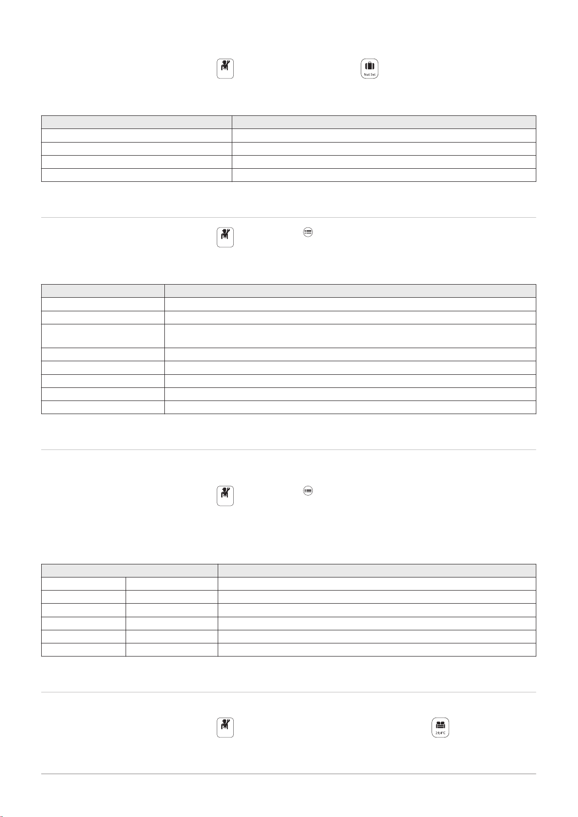
1. Select the Holiday Mode icon.
Off
Off
Off
Off
7717201 - v03 - 25062019 MID _HMI T-control - Gas 120 ACE 41
2. Set the following parameters:
Tab.22
Parameter Description
Start date holiday Set the date and time for the start of the absence period.
End date holiday Set the date and time for the end of the absence period.
Wished room temperature during holiday Set the desired room temperature for the absence period
Reset Restart or cancel the holiday programme
8 Operation
8.4
Changing the basic settings
1. Press the key.
2. Select System Settings.
3. Carry out one of the following operations:
Tab.23
Menu Description
Set Date and Time Setting the date and time
Select Country and Language Select the country and language.
Daylight Saving Time
Setting the automatic change to daylight saving time. These changes will be carried out on the
last Sunday in March and October
Installer Details Display the installer details
Set Heating Activity Names Personalise the name of the activities
Set Screen Brightness Setting the screen brightness
Set click sound Switch the sound of the rotary knob on or off
License Information Display the creation licenses for the internal software
8.5 Changing the name of an activity
You can change the names of the activities. The modification applies to all
of the zones.
1. Press the key.
2. Select System Settings.
3. Select Set Heating Activity Names.
4. Select the activity you want to change.
5. Change the name of the activity (10 characters max.).
Tab.24
Factory setting Customer setting
Activity 1: Sleep
Activity 2: Home
Activity 3: Away
Activity 4: Morning
Activity 5: Evening
Activity 6: Custom
8.6
Personalising the name and symbol for a zone
It is possible to personalise the name and symbol for a zone.
1. Select the icon for the zone to be modified; , for example.
2. Select Zone configuration.
3. Select Friendly Name of the user zone.
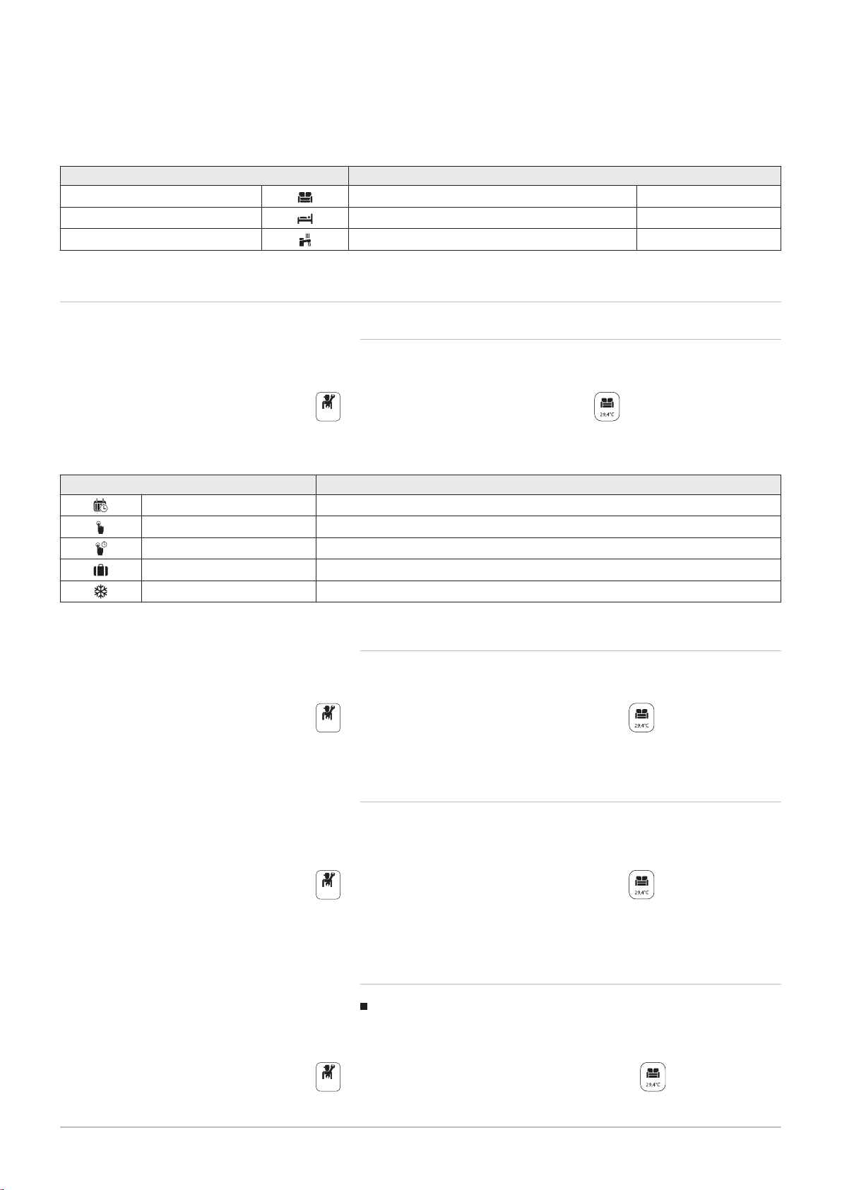
Off
Off
Off
Off
8 Operation
42 MID _HMI T-control - Gas 120 ACE 7717201 - v03 - 25062019
Tab.25
CIRCB
CH
DHW
4. Modify the name of the zone (20 characters max.).
5. Select Icon display zone.
6. Modify the linked symbol.
Factory-set name and symbol Customer-set name and symbol
8.7
Room temperature for a zone
8.7.1 Selecting the operating mode
To set the room temperature for the different living zones, you can choose
between five operating modes:
Tab.26
Mode Description
Scheduling
Manual
Short temperature change
Holiday
Antifrost
Selection of a timer programme
The room temperature is constant
The room temperature is forced for a defined period
The room temperature is reduced during an absence period to save energy
The installation and equipment are protected during the winter period
8.7.2 Changing the temperature settings of a zone
You can change the temperature settings of activities for the zone
selected.
1. Select the icon for the affected zone, , for example.
2. Select the desired operating mode:
1. Select the icon for the zone to be modified; , for example.
2. Select Set Heating Activity Temperatures.
3. Select the activity to change its temperature setting.
8.7.3 Changing the room temperature temporarily
Regardless of the operating mode selected for a zone, it is possible to
modify the room temperature for a defined period. Once this time has
elapsed, the selected operating mode will restart.
1. Select the icon for the zone to be modified; , for example.
2. Select Short temperature change.
3. Define the duration in Hour and in Minute.
4. Set the Temporary room setpoint per zone parameter.
8.7.4 Timer programming for heating
Activating timer programming mode
In order to use the timer programme, the timer programming (Scheduling)
mode must be activated. This is activated for each zone individually.
1. Select the icon for the zone to be configured, , for example.
2. Select Zone configuration > ZoneCurrentMode > Scheduling.

Off
Heating Schedule
Zone setup Z...
14 : 23
Sunday
6:00 House
20.0°C
Edit schedule entry
6:00
House 20.0°C
22.00
Nuit
16.00°C
Add time and Activity
Copy to other day
Set activity temperatures
MW-5000770-2
Off
Off
Off
8 Operation
7717201 - v03 - 25062019 MID _HMI T-control - Gas 120 ACE 43
Creating a timer programme for heating
A timer programme can be used to vary the room temperature in a living
zone depending on activities during the day. This can be programmed for
each day of the week.
1. Select the icon for the zone to be programmed, , for example.
Fig.54
8.8 Domestic hot water temperature
2. Select Zone configuration > Heating Schedule.
3. Select the programme to be modified.
The programmed activities for Sunday are displayed.
The last activity of the day remains active until the first activity of the
following day.
4. Select the day to be modified.
5. Carry out the following actions according to your needs:
Modify the timings for programmed activities.
Add a new activity.
Delete a programmed activity (choose the activity "Delete").
Copy programmed daily activities to other days.
Modify temperatures linked to an activity.
Selecting a timer programme
In the Timer programming operating mode, three programs are available
per zone. Each program is independent.
To select a timer programme for a zone:
1. Select the icon for the affected zone, , for example.
2. Select Scheduling.
3. Select the desired timer programme.
8.8.1 Selecting the operating mode
Tab.27
Mode Description
Scheduling
Manual
Hot water boost
Holiday
Antifrost
For the production of domestic hot water, you can choose between five
operating modes.
1. Select the icon for the DHW zone.
2. Select the desired operating mode:
Selection of a timer programme
The domestic hot water temperature remains at the comfort temperature
permanently
The production of domestic hot water is forced at the comfort temperature
for a defined duration
The domestic hot water temperature is reduced during an absence period
to save energy
The installation and equipment are protected during the winter period
8.8.2 Forcing domestic hot water production (override)
Regardless of the selected operating mode, you can force domestic hot
water protection to the comfort temperature for a defined duration.
1. Select the icon for the DHW zone.
2. Select Hot water boost.
3. Define the duration in Hour and in Minute.

Off
Off
Off
DHW1: DHW Schedule
Zone setup...Zo...
14 : 23
Sunday
6:00 Comfort
55.0°C
Edit schedule entry
6:00
Comfort 55.0°C
Add time and Activity
Copy to other day
Set activity temperatures
MW-2000750-2
Off
8 Operation
44 MID _HMI T-control - Gas 120 ACE 7717201 - v03 - 25062019
8.8.3 Modifying the domestic hot water set point temperatures
You can modify the "Comfort domestic hot water" and "Reduced domestic
hot water" set point temperatures.
1. Select the icon for the DHW zone.
2. Select one of the following menus:
Menu Description
ComfortZoneDHWtemp Only modify the "Comfort domestic hot water" set point tem
perature
Zone configuration > Domestic Hot Water Setpoints Modify the "Comfort domestic hot water" and "Reduced do
mestic hot water" set point temperatures.
8.8.4 Timer programming for domestic hot water
Activating timer programming mode
In order to use the timer programme, the timer programming (Scheduling)
mode must be activated. This is activated for each zone individually.
1. Select the icon for the DHW zone.
2. Select Zone configuration > OperatingZoneMode > Scheduling.
Fig.55
Creating a timer programme for domestic hot water
A timer programme can be used to vary the domestic hot water
temperature depending on activities during the day. This can be
programmed for each day of the week.
1. Select the icon for the DHW zone.
2. Select Zone configuration > DHW Schedule.
3. Select the programme to be modified.
The programmed activities for Sunday are displayed.
The last activity of the day remains active until the first activity of the
following day.
4. Select the day to be modified.
5. Carry out the following actions according to your needs:
Modify the timings for programmed activities.
Add a new activity.
Delete a programmed activity (choose the activity "Delete").
Copy programmed daily activities to other days.
Modify temperatures linked to an activity.
Selecting a timer programme
In the Timer programming operating mode, three programs are available.
To select a timer programme:
1. Select the icon for the DHW zone.
2. Select Scheduling.
3. Select the desired timer programme.

9 Settings
Off
On
MW-5000765-3
Slope: 1.5
Max: 90˚C
Base: 20˚C
50˚C;0˚C
Heating curve
14 : 23
Zone setup
On
7717201 - v03 - 25062019 MID _HMI T-control - Gas 120 ACE 45
9.1 Accessing the Installer level
9 Settings
Certain parameters, which may affect the operation of the appliance, are
protected by an access code. Only the installer is authorised to modify
these parameters.
To access the installer level:
9.2 Setting the heating curve
Fig.56
1. Select the
icon.
2. Enter the code 0012.
The Installer level is activated On. After modifying the desired
settings, exit the Installer level.
3. To exit the Installer level, select the On icon, then Confirm.
If no actions are taken for 30 minutes, the system will automatically exit
the Installer level.
The relationship between the outdoor temperature and the central heating
flow temperature is controlled by a heating curve. This can be adjusted
according the requirements of the installation.
To set the heating curve for a zone:
1. Select the icon for the zone to be modified; , for example.
2. Select Heating Curve.
3. Set the following parameters:
Tab.28
Parameter Description
Slope: Value of the heating curve gradient.
underfloor heating circuit: gradient between 0.4 and 0.7
radiator circuit: gradient of approx. 1.5
Max: Maximum temperature of the circuit
Base: Curve base point temperature (default value: Off = auto
matic mode).
If Base: Off, the curve base point temperature becomes
equal to the room set point temperature
50 °C; 0 °C Water temperature in the circuit for an outdoor tempera
ture. This data is visible all along the curve.
9.3
Drying screed
The screed drying function reduces the drying time of the screed for
underfloor heating. This function can be activated for individual zones.
Every day at midnight, the set point temperature is recalculated and the
number of days is decreased.
To activate this function:
1. Select the icon for the zone to be activated, , for example.
2. Select Set Screed Drying.

MW-5000764-1
10 9 8 7 6 5 4 3 2 1
23
20
26
29
32
35
38
41
44
47
° C
00:00 00:00 00:00
1
2
3
OnOnOn
9 Settings
46 MID _HMI T-control - Gas 120 ACE 7717201 - v03 - 25062019
Fig.57
3. Set the following parameters:
Parameters Description
Zone screed drying Number of days of drying (1)
ScreedStartTemp Drying start temperature (2)
ScreedStopTemp Drying end temperature (3)
The screed drying programme will start immediately and continue for the
selected number of days.
At the end of the programme, the selected operating mode will restart.
Tab.29 Example: Adjustment of the temperature setting every 7 days
Days Start temperature End temperature Temperature variation
1 to 7 +25 °C +55 °C Temperature increased every day by 5 °C
8 to 14 +55 °C +55 °C Temperature maintained at +55 °C without dropping at night
15 to 21 +55 °C +25 °C Temperature decreased every day by 5 °C
9.4
Configuring the maintenance message
The boiler control panel is used to display a message whenever a service
is necessary.
To configure the maintenance message:
1. Select the Maintenance icon.
2. Select Service notification.
3. Select the desired type of notification:
Type of notification: Description
None No maintenance message
Custom notification The maintenance message will be displayed once the burner operating hours defined
by the Service Burning hrs parameter have elapsed
ABC notification Recommended setting
The maintenance message will be displayed according to the power input (energy val
ue):
Gas 120 ACE - 65 : 90,000 kWh
Gas 120 ACE - 90 : 135,000 kWh
Gas 120 ACE - 115 : 180,000 kWh
9.5
Saving the installer details
The name and phone number of the installer can be saved so that the
user can find it easily.
1. Press the key.
2. Select System Settings > Installer Details.
3. Enter the name and phone number.
9.6
Saving the commissioning settings
You can save all installation-specific settings. These settings can be
restored if necessary, for example after replacement of the main electronic
control system board.
1. Press the key.
2. Select Advanced Service Menu > Save as commissioning settings.
3. Select Confirm to save the settings.

When you have saved the commissioning settings, the option Revert
OnOnOnOnOn
7717201 - v03 - 25062019 MID _HMI T-control - Gas 120 ACE 47
commissioning settings is available in the Advanced Service Menu.
9.7 Resetting or re-establishing the parameters.
9.7.1 Resetting after replacing the PCB
Configuration numbers must be reset if the boiler or burner safety unit
PCB is replaced.
The configuration numbers can be found on the data plate of the boiler.
To reset the configuration numbers:
1. Press the key.
2. Select Advanced Service Menu > Set Configuration Numbers.
3. Select CU-GH-08.
4. Select and change the CN1 setting.
5. Select and change the CN2 setting.
6. Select Confirm to confirm the modifications.
9 Settings
9.7.2
Use this function after replacing a boiler PCB in order to detect all the
devices connected to the CAN bus.
To detect devices connected to the CAN bus:
1. Press the key.
2. Select Advanced Service Menu > Auto Detect.
3. Select Confirm to carry out the auto-detect.
Auto-detecting options and accessories
9.7.3 Reverting to the commissioning settings
If the commissioning settings were saved, you can revert to the values
specific to your installation.
To revert to the commissioning settings
1. Press the key.
2. Select Advanced Service Menu > Revert commissioning settings.
3. Select Confirm to revert to the commissioning settings.
9.7.4
To revert to the factory settings for the boiler:
1. Press the key.
2. Select Advanced Service Menu > Reset to Factory Settings.
3. Select Confirm to revert to the factory settings.
Reverting to the factory settings
9.8
Component Description
Appliance Info Information about the boiler
CU-GH-08 Information about the boiler central unit PCB
MK3 -
Accessing information on the hardware and software versions
Information on the hardware and software versions for the appliance's
various components is stored in the control panel.
To access:
1. Press the key.
2. Select Version Information.
3. Select the component for which you would like to see the version
information.
HMI T-control
Information about the control panel
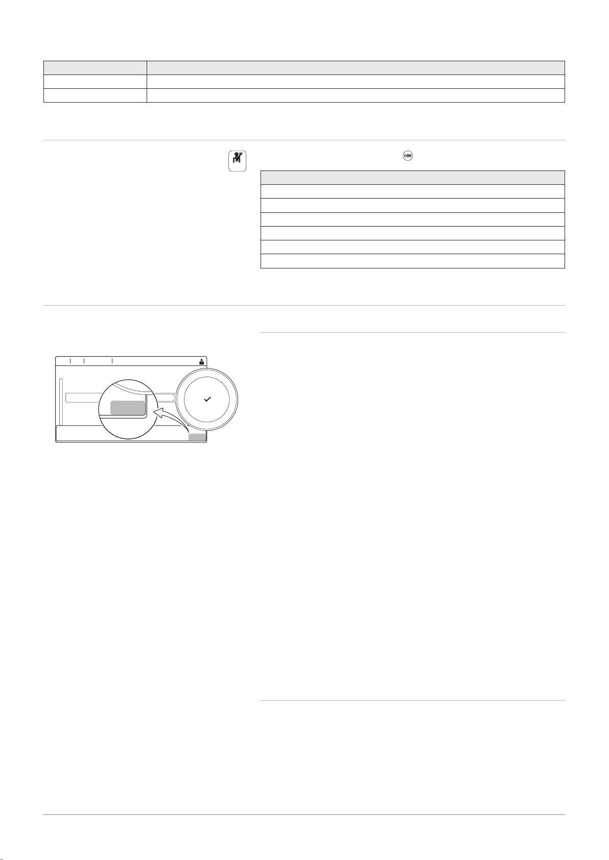
On
AD-3001373-02
00:12
...... ......
........ .......
........ .......
....................
..... ... ....... .... .. ..... ....... .... ..... .......
..... ... ....... .... .. ..... ....
.........
..... ... ....... ....
..... ... ....... ....
....... .... .. ..... .... .......
....... ...........
......
.....
...
CP010
CP010
AD-3001375-01
CP010
AD-3001376-01
CP010
AD-3001377-01
CP010
9 Settings
48 MID _HMI T-control - Gas 120 ACE 7717201 - v03 - 25062019
Component Description
SCB-02 Information about the PCB controlling the zones for heating and domestic hot water
CB-09 Information on the input/output control PCB
9.9 Menu tree
Level 1 menus accessible with the button:
Level 1 menu
Installation Setup
Commissioning Menu
Advanced Service Menu
Error History
System Settings
Version Information
9.10
List of parameters
Fig.58 Code on a OEtroCom-3
Fig.59 First letter
Fig.60 Second letter
9.10.1 Introduction to parameter codes
The controls platform makes use of an advanced system to categorise
parameters, measurements and counters. Knowing the logic behind these
codes, makes it easier to identify them. The code consists of two letters
and three numbers.
The first letter is the category the code relates to.
A Appliance: Appliance
C Circuit: Zone
D Domestic hot water: Domestic hot water
G Gas fired: Gas-fired heat engine
P Producer: Central heating
Category D codes are appliance controlled only. When the domestic hot
water is controlled by an SCB, it is handled like a circuit, with C-category
codes.
The second letter is the type.
P Parameter: Parameters
C Counter: Counters
M Measurement: Signals
Fig.61 Number
The number is always three digits. In certain cases, the last of the three
digits relates to a zone.
9.10.2 Changing the parameters
The boiler’s control unit is set for the most common central heating
systems. These settings will ensure that virtually every central heating
system operates effectively. The user or the installer can optimise the
parameters as required.

Caution
7717201 - v03 - 25062019 MID _HMI T-control - Gas 120 ACE 49
Changing the factory settings may adversely affect the operation
of the boiler.
9.10.3 Control unit settings
Important
All tables show the factory setting for the parameters.
The tables also list parameters that are only applicable if the
boiler is combined with other equipment such as an outdoor
sensor.
All possible options are indicated in the adjustment range. The
display of the boiler only shows the relevant settings for the
appliance.
Tab.30 Navigation for BASIC INSTALLER level
Level Menu cascade
Basic installer
(1) See the column "Submenu" in the following table for the correct navigation. The parameters are grouped in specific functionalities.
> Installation Setup > CU-GH08 > Submenu
(1)
> Parameters, counters, signals > Parameters
9 Settings
Tab.31 Factory settings at BASIC INSTALLER level
Code Display text Description Range Gas 120
ACE - 65
AP016 CH function on Enable central heating heat
demand processing
AP017 DHW function on Enable domestic hot water
heat demand processing
AP073 Summer Winter Outdoor temperature: upper
0 = Off
1 1 1
1 = On
0 = Off
1 1 1
1 = On
10 °C - 30 °C 22 22 22
Gas 120
ACE - 90
Gas 120
ACE - 115
limit for heating
AP074 Force summer
mode
The heating is stopped. Hot
water is maintained. Force
0 = Off
1 = On
0 0 0
Summer Mode
AP083 Enable master
func
Enable the master functionality
of this device on the S-Bus for
0 = No
1 = Yes
0 0 0
system control
AP089 Installer name Name of the installer - None None None
AP090 Installer phone Telephone number of the
- 0 0 0
installer
CP510 Temporary Room
Setp
Temporary room setpoint per
zone
5 °C - 30 °C 20 20 20
Tab.32 Navigation for INSTALLER level
Level Menu cascade
Installer
(1) See the column "Submenu" in the following table for the correct navigation. The parameters are grouped in specific functionalities.
> Installation Setup > CU-GH08 > Submenu
(1)
> Parameters, counters, signals > Parameters

9 Settings
50 MID _HMI T-control - Gas 120 ACE 7717201 - v03 - 25062019
Tab.33 Factory settings at INSTALLER level
Code Display text Description Range Gas 120
ACE - 65
AP001 BL input setting Blocking input setting (1: Full
blocking, 2: Partial blocking, 3:
User reset locking)
Blocking input setting (1: Full
blocking, 2: Partial blocking, 3:
User reset locking)
1 = Full blocking
2 = Partial blocking
3 = User reset locking
4 = Backup relieved
5 = Generator relieved
6 = Gen.&Backup
1 1 1
relieved
7 = High, Low Tariff
8 = Photovoltaic HP
Only
9 = PV HP And backup
10 = Smart Grid ready
11 = Heating Cooling
AP008 Time release
signal
The appliance will wait x sec
(0=off) for the release contact
0 Sec - 255 Sec 0 0 0
to close in order to start the
burner
AP009 Service hours
burner
AP010 Service
notification
AP011 Service hours
mains
AP014 Auto Filling Setting to enable or disable the
AP023 Filling Inst
Timeout
Burning hours before raising a
service notification
The type of service needed
based on burn and powered
hours
Hours powered to raise a
service notification
automatic refill device. It can
be set to auto, manual or off
Maximum time the automatic
filling procedure may last at
0 Hours - 51000 Hours 6000 6000 6000
0 = None
2 2 2
1 = Custom notification
2 = ABC notification
0 Hours - 51000 Hours 35000 35000 35000
0 = Disabled
0 0 0
1 = Manual
2 = Auto
0 Min - 90 Min 10 10 10
installation
AP051 Filling Interval The minimum time that is
0 Days - 65535 Days 90 90 90
allowed between two top-up
fillings
AP063 CH Set Max
System
Maximum flow temperature
setpoint for burning at central
20 °C - 90 °C 90 90 90
heating
AP069 Top up timeout Maximum time the automatic
0 Min - 60 Min 2 2 2
topping up procedure may last
AP070 Operational
Pressure
The operational water pressure
the device should be working
0 bar - 2.5 bar 1,8 1,8 1,8
on
AP071 InstallMaxTimeOutMaximum time that is needed
0 Sec - 3600 Sec 0 0 0
to fill the complete installation
AP079 Building Inertia Inertia of the building used for
0 - 15 3 3 3
heat up speed
AP080 Frost min out
temp
Outside temperature below
which the antifreeze protection
-60 °C - 25 °C -10 -10 -10
is activated
AP082 Enable daylight
save
Enable daylight saving for the
system to save energy during
0 = Off
1 = On
1 1 1
winter
AP091 Outside Sens.
Source
Type of outside sensor
connection to be used
0 = Auto
1 = Wired sensor
0 0 0
2 = Wireless sensor
3 = Internet measured
4 = None
Gas 120
ACE - 90
Gas 120
ACE - 115

9 Settings
7717201 - v03 - 25062019 MID _HMI T-control - Gas 120 ACE 51
Code Display text Description Range Gas 120
ACE - 65
AP108 OutsideSensorEn
abled
Enable the function Outside
Sensor
0 = Auto
1 = Wired sensor
0 0 0
Gas 120
ACE - 90
Gas 120
ACE - 115
2 = Wireless sensor
3 = Internet measured
4 = None
CP000 MaxZoneTFlowS
etpoint
GP017 Max power Maximum power percentage in
Maximum Flow Temperature
setpoint zone
0 °C - 90 °C 80 80 80
0 kW - 80 kW 103,6 124,5 140,9
kilo Watt
GP050 Power Min Minimum power in kilo Watt for
0 kW - 80 kW 6,7 10,8 11,4
RT2012 calculation
PP015 CH Pump postrun
time
Central heating pump post run
time
0 Min - 99 Min 1 1 1
Tab.34 Navigation for ADVANCED INSTALLER level
Level Menu cascade
Advanced installer
> Installation Setup > CU-GH08 > Submenu
(1)
> Parameters, counters, signals > Parameters > Adv.
Parameters
(1) See the column "Submenu" in the following table for the correct navigation. The parameters are grouped in specific functionalities.
Tab.35 Factory settings at ADVANCED INSTALLER level
Code Display text Description Range Gas 120
ACE - 65
AP002 Manual Heat
Demand
Enable manual heat demand
function
0 = Off
1 = With setpoint
0 0 0
Gas 120
ACE - 90
Gas 120
ACE - 115
2 = TOutdoor Control
AP026 Setpoint manual HDFlow temperature setpoint for
10 °C - 90 °C 40 40 40
manual heat demand
AP056 Outdoor sensor Enable outdoor sensor 0 = No outside sensor
1 1 1
1 = AF60
2 = QAC34
AP077 Max. display level Maximum Level of parameters
and signals to display on MK
1 = End user
2 = Installer
3 3 3
3 = Installer advanced
4 = Lab
5 = Controls
Development
AP102 Boiler Pump
function
Configuration of the boiler
pump as zone pump or system
0 = No
1 = Yes
0 0 0
pump (feed lowloss header)
AP111 Can line length Can line length 0 = < 3m
0 0 0
1 = < 80m
2 = < 500m
CP130 T.OutdoorToZone Assigning the outdoor sensor
0 - 4 0 0 0
to zone …
GP007 Fan RPM Max CHMaximum fan speed during
1400 Rpm - 7000 Rpm 5600 6300 6800
Central Heating mode
GP008 Fan RPM Min Minimum fan speed during
1400 Rpm - 4000 Rpm 1600 1600 1750
Central Heating + Domestic
Hot Water mode
GP009 Fan RPM Start Fan speed at appliance start 1000 Rpm - 4000 Rpm 2500 2500 2500
GP010 GPS Check Gas Pressure Switch check
on/off
GP021 Temp diff
Modulating
Modulate back when delta
temperature is large then this
0 = No
0 0 0
1 = Yes
10 °C - 40 °C 25 25 20
treshold

9 Settings
52 MID _HMI T-control - Gas 120 ACE 7717201 - v03 - 25062019
Code Display text Description Range Gas 120
ACE - 65
GP022 Tfa Filter Tau Tau factor for average flow
1 - 255 1 1 1
Gas 120
ACE - 90
temperature calculation
PP014 ChPumpDTRedu
ction
Reduction of temperature delta
modulating for pump
0 °C - 40 °C 18 18 18
modulation
PP016 Max. CH pump
speed
PP017 ChPumpSpeedM
axFactor
Maximum central heating pump
speed (%)
Maximum central heating at
minimum load as percentage of
20 % - 100 % 100 100 100
0 % - 100 % 100 100 100
max pump speed
PP018 Min CH pump
speed
PP023 Start hysteresis CHHysteresis to start burner in
Minimum central heating pump
speed (%)
20 % - 100 % 30 30 30
1 °C - 10 °C 10 10 10
heating mode
9.10.4 List of parametersSCB-02
Tab.36
Parameter Text display Description
CP000 MaxZoneTFlowSetpointMaximum Flow Temperature setpoint zone
Adjustment range:
from 7 °C to 90 °C
CP001 MaxZoneTFlowSetpointMaximum Flow Temperature setpoint zone
Adjustment range:
from 7 °C to 90 °C
CP010 Tflow setpoint zone Zone flow temperature setpoint, used when the zone is set to a fixed flow
setpoint.
Adjustment range:
from 7 °C to 95 °C
CP011 Tflow setpoint zone Zone flow temperature setpoint, used when the zone is set to a fixed flow
setpoint.
Adjustment range:
from 7 °C to 95 °C
CP020 Zone Function Functionality of the zone
Adjustment range:
0 =Disable
1 =Direct
2 =Mixing Circuit
3 =Swimming pool
4 =High Temperature
5 =Fan Convector
6 =DHW tank
7 =Electrical DHW
8 =Time Program
9 =ProcessHeat
10 =DHW Layered
11 =DHW Internal tank
12 =DHW Commercial Tank
31 =DHW FWS EXT
Gas 120
ACE - 115
Factory
setting
90
55
90
50
6

9 Settings
7717201 - v03 - 25062019 MID _HMI T-control - Gas 120 ACE 53
Parameter Text display Description
CP021 Zone Function Functionality of the zone
Adjustment range:
0 =Disable
1 =Direct
2 =Mixing Circuit
3 =Swimming pool
4 =High Temperature
5 =Fan Convector
6 =DHW tank
7 =Electrical DHW
8 =Time Program
9 =ProcessHeat
10 =DHW Layered
11 =DHW Internal tank
12 =DHW Commercial Tank
31 =DHW FWS EXT
CP040 Postrun zone pump Pump post runtime of the zone
Adjustment range:
from 0 Min to 99 Min
CP041 Postrun zone pump Pump post runtime of the zone
Adjustment range:
from 0 Min to 99 Min
CP060 RoomT. Holiday Wished room zone temperature on holiday period
Adjustment range:
from 5 °C to 20 °C
CP061 RoomT. Holiday Wished room zone temperature on holiday period
Adjustment range:
from 5 °C to 20 °C
CP070 MaxReducedRoomT.LimMax Room Temperature limit of the circuit in reduced mode, that allows
switching to comfort mode
Adjustment range:
from 5 °C to 30 °C
CP071 MaxReducedRoomT.LimMax Room Temperature limit of the circuit in reduced mode, that allows
switching to comfort mode
Adjustment range:
from 5 °C to 30 °C
CP080 User T.Room Activity Room setpoint temperature of the user zone activity
Adjustment range:
from 5 °C to 30 °C
CP081 User T.Room Activity Room setpoint temperature of the user zone activity
Adjustment range:
from 5 °C to 30 °C
CP082 User T.Room Activity Room setpoint temperature of the user zone activity
Adjustment range:
from 5 °C to 30 °C
CP083 User T.Room Activity Room setpoint temperature of the user zone activity
Adjustment range:
from 5 °C to 30 °C
CP084 User T.Room Activity Room setpoint temperature of the user zone activity
Adjustment range:
from 5 °C to 30 °C
CP085 User T.Room Activity Room setpoint temperature of the user zone activity
Adjustment range:
from 5 °C to 30 °C
Factory
setting
2
2
4
6
6
16
16
16
16
16
16
16
16

9 Settings
54 MID _HMI T-control - Gas 120 ACE 7717201 - v03 - 25062019
Parameter Text display Description
CP086 User T.Room Activity Room setpoint temperature of the user zone activity
Adjustment range:
from 5 °C to 30 °C
CP087 User T.Room Activity Room setpoint temperature of the user zone activity
Adjustment range:
from 5 °C to 30 °C
CP088 User T.Room Activity Room setpoint temperature of the user zone activity
Adjustment range:
from 5 °C to 30 °C
CP089 User T.Room Activity Room setpoint temperature of the user zone activity
Adjustment range:
from 5 °C to 30 °C
CP090 User T.Room Activity Room setpoint temperature of the user zone activity
Adjustment range:
from 5 °C to 30 °C
CP091 User T.Room Activity Room setpoint temperature of the user zone activity
Adjustment range:
from 5 °C to 30 °C
CP200 Manu
ZoneRoomTempSet
Manually setting the room temperature setpoint of the zone
Adjustment range:
from 5 °C to 30 °C
CP201 Manu
ZoneRoomTempSet
Manually setting the room temperature setpoint of the zone
Adjustment range:
from 5 °C to 30 °C
CP210 Zone HCZP Comfort Comfort footpoint of the temperature of heat curve of the circuit
Adjustment range:
from 15 °C to 90 °C
CP211 Zone HCZP Comfort Comfort footpoint of the temperature of heat curve of the circuit
Adjustment range:
from 15 °C to 90 °C
CP220 Zone HCZP Reduced Reduced footpoint of the temperature of heat curve of the circuit
Adjustment range:
from 15 °C to 90 °C
CP221 Zone HCZP Reduced Reduced footpoint of the temperature of heat curve of the circuit
Adjustment range:
from 15 °C to 90 °C
CP230 Zone Heating Curve Heating curve temperature gradient of the zone
Adjustment range:
from 0 to 4
CP231 Zone Heating Curve Heating curve temperature gradient of the zone
Adjustment range:
from 0 to 4
CP240 ZoneRoomUnitInfl Adjustment of the influence of the zone room unit
Adjustment range:
from 0 to 10
CP241 ZoneRoomUnitInfl Adjustment of the influence of the zone room unit
Adjustment range:
from 0 to 10
CP250 CalSondeAmbZone Calibration of Zone Room Unit
Adjustment range:
from -5 °C to 5 °C
Factory
setting
16
16
16
16
16
16
20
20
15
15
15
15
0.7
0.7
3
3
0

9 Settings
7717201 - v03 - 25062019 MID _HMI T-control - Gas 120 ACE 55
Parameter Text display Description
CP251 CalSondeAmbZone Calibration of Zone Room Unit
Adjustment range:
from -5 °C to 5 °C
CP290 ConfigZonePumpOut Configuration of Zone Pump Output
Adjustment range:
0 =Zone output
1 =CH mode
2 =DHW mode
3 =Cooling mode
4 =Error report
5 =Burning
6 =Service flag
7 =System error
8 =DHW looping
9 =Primary pump
10 =Buffer pump
CP291 ConfigZonePumpOut Configuration of Zone Pump Output
Adjustment range:
0 =Zone output
1 =CH mode
2 =DHW mode
3 =Cooling mode
4 =Error report
5 =Burning
6 =Service flag
7 =System error
8 =DHW looping
9 =Primary pump
10 =Buffer pump
CP320 OperatingZoneMode Operating mode of the zone
Adjustment range:
0 =Scheduling
1 =Manual
2 =Antifrost
3 =Temporary
CP321 OperatingZoneMode Operating mode of the zone
Adjustment range:
0 =Scheduling
1 =Manual
2 =Antifrost
3 =Temporary
CP340 TypeReducedNightModeType of reduced night mode, stop or maintain heating of circuit
Adjustment range:
0 =Stop heat demand
1 =Continue heat demand
CP341 TypeReducedNightModeType of reduced night mode, stop or maintain heating of circuit
Adjustment range:
0 =Stop heat demand
1 =Continue heat demand
CP470 Zone screed drying Setting of the screed drying program of the zone
Adjustment range:
0 Days =30 Days
Factory
setting
0
0
0
1
1
1
1
0

9 Settings
56 MID _HMI T-control - Gas 120 ACE 7717201 - v03 - 25062019
Parameter Text display Description
CP471 Zone screed drying Setting of the screed drying program of the zone
Adjustment range:
0 Days =30 Days
CP480 ScreedStartTemp Setting of the start temperature of the screed drying program of the zone
Adjustment range:
from 20 °C to 50 °C
CP481 ScreedStartTemp Setting of the start temperature of the screed drying program of the zone
Adjustment range:
from 20 °C to 50 °C
CP490 ScreedStopTemp Setting of the stop temperature of the screed drying program of the zone
Adjustment range:
from 20 °C to 50 °C
CP491 ScreedStopTemp Setting of the stop temperature of the screed drying program of the zone
Adjustment range:
from 20 °C to 50 °C
CP510 Temporary Room Setp Temporary room setpoint per zone
Adjustment range:
from 5 °C to 30 °C
CP511 Temporary Room Setp Temporary room setpoint per zone
Adjustment range:
from 5 °C to 30 °C
CP520 Zone Power setpoint Power setpoint per zone
Adjustment range:
from 0 % to 100 %
CP521 Zone Power setpoint Power setpoint per zone
Adjustment range:
from 0 % to 100 %
CP530 Zone PWM Pump
speed
Pulse Width Modulation pump speed per zone
Adjustment range:
from 20 % to 100 %
CP531 Zone PWM Pump
speed
Pulse Width Modulation pump speed per zone
Adjustment range:
from 20 % to 100 %
CP550 Zone, fire place Fire Place mode is active
Adjustment range:
0 =Off
1 =On
CP551 Zone, fire place Fire Place mode is active
Adjustment range:
0 =Off
1 =On
CP570 ZoneTimeProg Select Time Program of the zone selected by the user
Adjustment range:
0 =Schedule 1
1 =Schedule 2
2 =Schedule 3
3 =Cooling
CP571 ZoneTimeProg Select Time Program of the zone selected by the user
Adjustment range:
0 =Schedule 1
1 =Schedule 2
2 =Schedule 3
3 =Cooling
Factory
setting
0
20
20
20
20
20
20
100
100
100
100
0
0
0
0

9 Settings
7717201 - v03 - 25062019 MID _HMI T-control - Gas 120 ACE 57
Parameter Text display Description
CP660 Icon display zone Choice icon to display this zone
Adjustment range:
0 =None
1 =All
2 =Bedroom
3 =Livingroom
4 =Study
5 =Outdoor
6 =Kitchen
7 =Basement
8 =Swimming Pool
9 =DHW Tank
10 =DHW Electrical Tank
11 =DHW Layered Tank
12 =Internal Boiler Tank
13 =Time Program
CP661 Icon display zone Choice icon to display this zone
Adjustment range:
0 =None
1 =All
2 =Bedroom
3 =Livingroom
4 =Study
5 =Outdoor
6 =Kitchen
7 =Basement
8 =Swimming Pool
9 =DHW Tank
10 =DHW Electrical Tank
11 =DHW Layered Tank
12 =Internal Boiler Tank
13 =Time Program
CP670 ConfPairing RU Zone Configuration of pairing room unit per zone
CP671 ConfPairing RU Zone Configuration of pairing room unit per zone
CP730 Zone Heat up speed Selection of heat up speed of the zone
Adjustment range:
0 =Extra Slow
1 =Slowest
2 = Slower
3 = Normal
4 = Faster
5 =Fastest
CP731 Zone Heat up speed Selection of heat up speed of the zone
Adjustment range:
0 =Extra Slow
1 =Slowest
2 = Slower
3 = Normal
4 = Faster
5 =Fastest
CP740 Zone cool down speed Selection of cool down speed of the zone
Adjustment range:
0 =Slowest
1 =Slower
2 =Normal
3 =Faster
4 =Fastest
Factory
setting
0
0
3
3
2

9 Settings
58 MID _HMI T-control - Gas 120 ACE 7717201 - v03 - 25062019
Parameter Text display Description
CP741 Zone cool down speed Selection of cool down speed of the zone
Adjustment range:
0 =Slowest
1 =Slower
2 =Normal
3 =Faster
4 =Fastest
CP750 MaxZone Preheat time Maximum zone preheat time
Adjustment range:
from 0 Min to 240 Min
CP751 MaxZone Preheat time Maximum zone preheat time
Adjustment range:
from 0 Min to 240 Min
CP780 Control strategy Selection of the control strategy for the zone
Adjustment range:
0 =Automatic
1 =Room Temp. based
2 =Outdoor Temp. based
3 =Outdoor & room based
CP781 Control strategy Selection of the control strategy for the zone
Adjustment range:
0 =Automatic
1 =Room Temp. based
2 =Outdoor Temp. based
3 =Outdoor & room based
Factory
setting
2
0
60
0
0

Tab.37
7717201 - v03 - 25062019 MID _HMI T-control - Gas 120 ACE 59
Parameter Text display Description
EP018 Status relay func. Status relay function
Adjustment range:
0 =No Action
1 =Alarm
2 =Alarm Inverted
3 =Burning
4 =Not burning
5 =Reserved
6 =Reserved
7 =Service request
8 =Boiler on CH
9 =Boiler on DHW
10 =CH pump on
11 =Locking or Blocking
12 =Cooling mode
EP019 Status relay func. Status relay function
Adjustment range:
0 =No Action
1 =Alarm
2 =Alarm Inverted
3 =Burning
4 =Not burning
5 =Reserved
6 =Reserved
7 =Service request
8 =Boiler on CH
9 =Boiler on DHW
10 =CH pump on
11 =Locking or Blocking
12 =Cooling mode
EP028 Function 10V-PWM Selects the function of the 0-10 Volt output
Adjustment range:
0 =0-10V 1 (Wilo)
1 =0-10V 2 (Gr. GENI)
2 =PWM signal (Solar)
3 =0-10V 1 limited
4 =0-10V 2 limited
5 =PWM signal limited
6 =PWM signal (UPMXL)
EP029 Source 10V-PWM Selects the source signal for the 0-10 Volt output
Adjustment range:
0 =PWM
1 =Requested power
2 =Actual power
9 Settings
Factory
setting
0
0
0
0
Tab.38
Parameter Text display Description Factory
AP056 Outdoor sensor Enable outdoor sensor
Adjustment range:
0 =No outside sensor
1 =AF60
2 =QAC34
AP073 Summer Winter Outdoor temperature: upper limit for heating
Adjustment range:
from 15 °C to 30.5 °C
setting
0
22

9 Settings
60 MID _HMI T-control - Gas 120 ACE 7717201 - v03 - 25062019
Parameter Text display Description Factory
setting
AP074 Force summer mode The heating is stopped. Hot water is maintained. Force Summer Mode
0
Adjustment range:
0 =Off
1 =On
AP079 Building Inertia Inertia of the building used for heat up speed
3
Adjustment range:
from 0 to 10
AP080 Frost min out temp Outside temperature below which the antifreeze protection is activated
-10
Adjustment range:
from -30 °C to 20 °C
AP091 Outside Sens. Source Type of outside sensor connection to be used
0
Adjustment range:
0 =Auto
1 =Wired sensor
2 =Wireless sensor
3 =Internet measured
4 =None
AP077 Max. display level Maximum Level of parameters and signals to display on MK
2
Adjustment range:
1 =End user
2 =Installer
3 =Installer advanced
4 =Lab
5 =Controls Development
9.11 Reading out measured values
9.11.1 Control unit counters
Tab.39 Navigation for basic installer level
Level Menu path
Basic installer
(1) See the column "Submenu" in the following table for the correct navigation. The counters are grouped in specific functionalities.
> Installation Setup > CU-GH08 > Submenu
Tab.40 Counters at basic installer level
Code Display text Description Range Submenu
AC005 CH Energy
Consumed
AC006 DHW Energy
Consumed
Energy consumed for central
heating
Energy consumed for domestic
hot water
Tab.41 Navigation for installer level
Level Menu path
Installer
(1) See the column "Submenu" in the following table for the correct navigation. The counters are grouped in specific functionalities.
> Installation Setup > CU-GH08 > Submenu
(1)
> Parameters, counters, signals > Counters
0 kWh - 4294967294
Gas fired appliance
kWh
0 kWh - 4294967294
Gas fired appliance
kWh
(1)
> Parameters, counters, signals > Counters

Tab.42 Counters at installer level
7717201 - v03 - 25062019 MID _HMI T-control - Gas 120 ACE 61
Code Display text Description Range Submenu
AC001 Hours on mains Number of hours that the
appliance has been on mains
0 Hours - 4294967295
Hours
System Functionality
power
AC002 Service Burning
hrs
Number of hours that the
appliance has been producing
0 Hours - 131068 Hours Gas fired appliance
energy since last service
AC003 Hours Op. Service Number of hours since the
0 Hours - 131068 Hours Gas fired appliance
previous servicing of the
appliance
AC004 Burner Starts Number of generator startings
0 - 4294967294 Gas fired appliance
since the previous servicing.
AC016 Amount
Autofillings
AC026 Pump running
hours
AC027 Pump starts Counter that shows the number
Filling counter, count the
amount of automatic filling loops
Counter that shows the number
of pump running hours
0 - 65534 Auto filling CH
0 Hours - 65534 Hours Gas fired appliance
0 - 65534 Gas fired appliance
of pump starts
DC002 DHW valve cycles Numbers of Domestic Hot
Water diverting valve cycles
0 - 4294967294 Internal DHW
Tank DHW
Gas fired appliance
DC003 Hrs DHW 3wv Number of hours during which
the diverting valve is in DHW
0 Hours - 65534 Hours Tank DHW
Gas fired appliance
position
DC004 DHW burner starts Number of burner starts for
Domestic Hot Water
0 - 65534 Internal DHW
Tank DHW
Gas fired appliance
DC005 DHW burning
hours
Number of burning hours in
Domestic Hot Water
0 Hours - 65534 Hours Internal DHW
Tank DHW
Gas fired appliance
GC007 Failed starts Number of failed starts 0 - 65534 Gas fired appliance
PC001 ChCtrTotalPower
Cons.
PC002 Burner starts total Total number of burner starts.
Total power consumption used
by Central Heating
0 kW - 4294967294 kW Gas fired appliance
0 - 4294967294 Gas fired appliance
For heating and domestic hot
water
PC003 Hrs Burning total Total number of burning hours.
0 Hours - 65534 Hours Gas fired appliance
For heating and domestic hot
water
PC004 Burner flame loss Number of burner flame loss 0 - 65534 Gas fired appliance
9 Settings
9.11.2 SCB-02 counters
Tab.43 Zone Mixing valve
CC001 Zone Pump Run Hours Numbers of pump operating
hours of the zone
CC002 Zone Pump Run Hours Numbers of pump operating
hours of the zone
CC010 Zone Nbr Pump Starts Numbers of times the pump of
the zone has started
CC011 Zone Nbr Pump Starts Numbers of times the pump of
the zone has started
0 4294967295
0 4294967295
0 4294967295
0 4294967295

9 Settings
62 MID _HMI T-control - Gas 120 ACE 7717201 - v03 - 25062019
Tab.44 Zone High Temperatur
CC001 Zone Pump Run Hours Numbers of pump operating
hours of the zone
CC002 Zone Pump Run Hours Numbers of pump operating
hours of the zone
CC010 Zone Nbr Pump Starts Numbers of times the pump of
the zone has started
CC011 Zone Nbr Pump Starts Numbers of times the pump of
the zone has started
Tab.45 DHW tank
CC001 Zone Pump Run Hours Numbers of pump operating
hours of the zone
CC002 Zone Pump Run Hours Numbers of pump operating
hours of the zone
CC010 Zone Nbr Pump Starts Numbers of times the pump of
the zone has started
CC011 Zone Nbr Pump Starts Numbers of times the pump of
the zone has started
0 4294967295
0 4294967295
0 4294967295
0 4294967295
0 4294967295
0 4294967295
0 4294967295
0 4294967295
Tab.46 Process heat
CC001 Zone Pump Run Hours Numbers of pump operating
0 4294967295
hours of the zone
CC002 Zone Pump Run Hours Numbers of pump operating
0 4294967295
hours of the zone
CC010 Zone Nbr Pump Starts Numbers of times the pump of
0 4294967295
the zone has started
CC011 Zone Nbr Pump Starts Numbers of times the pump of
0 4294967295
the zone has started
Tab.47 Mandatory platform
AC001 Hours on mains Number of hours that the
0 Hours 4294967295 Hours
appliance has been on mains
power
9.11.3 Control unit signals
Tab.48 Navigation for basic installer level
Level Menu path
Basic installer
(1) See the column "Submenu" in the following table for the correct navigation. The signals are grouped in specific functionalities.
> Installation Setup > CU-GH08 > Submenu
(1)
> Parameters, counters, signals > Signals
Tab.49 Signals at basic installer level
Code Display text Description Range Submenu
Used descriptor
ver
No of status items Status bytes number of different
Version of the menu structure
that is being used for export
0 - 255 System Functionality
0 - 255 Gas fired appliance
items
Frost protect
active
Comfort mode
active
Frost protect is active 0 = No
1 = Yes
Comfort mode is active 0 = No
1 = Yes
Gas fired appliance
Tank DHW
Gas fired appliance

Code Display text Description Range Submenu
7717201 - v03 - 25062019 MID _HMI T-control - Gas 120 ACE 63
DHW blocking
active
Anti legionella act. Anti legionella is active 0 = Off
Domestic hot water preparation
blocking is active
0 = No
1 = Yes
1 = On
Gas fired appliance
Internal DHW
Tank DHW
Gas fired appliance
DHW active Domestic hot water preparation
is active
DHW Enabled Domestic hot water preparation
is enabled
CH Enabled Central heating production is
enabled
Struct loc DLS
PDO
Structure used to fill the location
and DLS PDO message.
Ini status give the device initialisation
status
0 = No
Gas fired appliance
1 = Yes
0 = No
Gas fired appliance
1 = Yes
0 = No
Gas fired appliance
1 = Yes
Mandatory bus master
0 = Not Done
System Functionality
1 = CheckObjPointerTable
2 = Default
3 = Read Configuration 1
4 = Read Configuration 2
5 = Read Custom Param.
6 = Finished
7 = Blocking Parameters
8 = PST Error
30 = WaitForConfiguration
HMI display info Trending string containing all
relevant information for
System Functionality
Gas fired appliance
diplaying appliance status on
the HMI MK2
RTC update on
CAN
Total
EnergyConsu Y0
Auto filling active Setting to enable or disable the
A Real Time Clock update has
been received on the CAN bus
Total energy consumed in the
current year
autofilling feature
0 = No
Mandatory bus master
1 = Yes
0 kWh - 4294967294 kWh Gas fired appliance
0 = Standby
Auto filling CH
1 = Filling Needed
2 = Filling Active
3 = Auto filling pending
ChimneyModeStatusStatus of the Chimney mode 0 = Off
Gas fired appliance
1 = Low power
2 = Medium power
3 = High power
4 = Cooling
AM001 DHW active Is the appliance currently in
domestic hot water production
mode?
0 = Off
1 = On
Internal DHW
Tank DHW
Gas fired appliance
AM010 Pump speed The current pump speed 0 % - 100 % Internal DHW
Gas fired appliance
AM011 Service required? Is service currently required? 0 = No
Gas fired appliance
1 = Yes
AM012 Status Appliance Current main status of the
appliance.
See
Status and sub-status,
Status information
System Functionality
page 67
AM014 Sub status
Appliance
Current sub status of the
appliance.
See
Status and sub-status,
Status information
System Functionality
page 67
AM015 Pump running? Is the pump running? 0 = Inactive
Gas fired appliance
1 = Active
9 Settings

9 Settings
64 MID _HMI T-control - Gas 120 ACE 7717201 - v03 - 25062019
Code Display text Description Range Submenu
AM016 System Flow
Temp
Flow temperature of appliance. -25 °C - 150 °C Zone manager
Internal DHW
Tank DHW
Producer Generic
Gas fired appliance
Prod. manager bridge
AM018 T return Return temperature of
appliance. The temperature of
the water entering the
appliance.
AM019 Water pressure Water pressure of the primary
circuit.
AM022 On / Off heat
On / Off heat demand 0 = Off
demand
AM027 Outside
temperature
Instantaneous outside
temperature
AM033 Next Service Ind. Next service indication 0 = None
-25 °C - 150 °C Zone manager
Internal DHW
Tank DHW
Gas fired appliance
0 bar - 4 bar Auto filling CH
Gas fired appliance
Gas fired appliance
1 = On
-60 °C - 60 °C Outdoor temperature
Gas fired appliance
Gas fired appliance
1 = A
2 = B
3 = C
4 = Custom
AM037 3 way valve Status of the three way valve 0 = CH
Gas fired appliance
1 = DHW
AM040 Control
temperature
AM046 Internet T.Outside Outside temperature received
Temperature used for hot water
control algorithms.
0 °C - 250 °C Internal DHW
Gas fired appliance
-70 °C - 70 °C Outdoor temperature
from an internet source
AP078 Out sensor
detected
Outside sensor detected in the
application
0 = No
1 = Yes
Outdoor temperature
DM002 DHWFlowSpeed Actual DHW combi flow rate 0 l/min - 25 l/min Internal DHW
DM029 DHW setpoint Domestic Hot Water
0 °C - 100 °C Internal DHW
temperature setpoint
GM001 Actual fan RPM Actual fan RPM 0 Rpm - 12000 Rpm Gas fired appliance
GM002 Fan RPM setpoint Actual fan RPM setpoint 0 Rpm - 12000 Rpm Gas fired appliance
GM008 Actual flame
Actual flame current measured 0 µA - 25 µA Gas fired appliance
current
Tab.50 Navigation for installer level
Level Menu path
Installer
(1) See the column "Submenu" in the following table for the correct navigation. The signals are grouped in specific functionalities.
> Installation Setup > CU-GH08 > Submenu
(1)
> Parameters, counters, signals > Signals
Tab.51 Signals at installer level
Code Display text Description Range Submenu
Error code Holds the error code in case of
0 - 65335 System Functionality
a warning, blocking or locking
CurrOrUpcomServ
Notif
Current or upcoming service
notification
0 = None
1 = A
Gas fired appliance
2 = B
3 = C
4 = Custom
PowerActualU8 Actual relative power produced
for PDO output
0 % - 100 % Zone manager
Gas fired appliance
PM-P Int. Interface
ZoneSysPowerRe
ceptPM
Current system power received
from power manager of the
0 % - 100 % Zone manager
zone

Code Display text Description Range Submenu
7717201 - v03 - 25062019 MID _HMI T-control - Gas 120 ACE 65
Zone SysTReturn PMCurrent system return
-327.68 °C - 327.67 °C Zone manager
temperature from power
manager of the zone
Request P to PM Request from the producer to
the producer manager to take
action
Actual power PM Actual power sent from the
producer manager
Producer Generic
Producer<>Consumer
Prod. manager bridge
0 % - 100 % Producer Generic
Producer<>Consumer
Prod. manager bridge
Time update stat RUTime update status for devices
Time R to L/S-bus
communicating via the RUbus
AM024 Actual rel. Power Actual relative power of the
0 % - 100 % Gas fired appliance
appliance
AM036 Flue gas
temperature
AM043 Pwr dwn reset
needed
AM101 Internal setpoint Internal system flow
Temperature of the exhaust gas
0 °C - 250 °C Gas fired appliance
leaving the appliance
A power down reset is needed 0 = No
1 = Yes
0 °C - 250 °C Gas fired appliance
Gas fired appliance
temperature setpoint
DM001 DHW tank temp
bottom
DM005 DhwSolarTankTempDomestic Hot Water solar tank
DM008 DHW out temp Temperature sensor for the tap
Domestic Hot Water tank
temperature (bottom sensor)
temperature
-25 °C - 150 °C Tank DHW
-25 °C - 150 °C Internal DHW
Tank DHW
-25 °C - 150 °C Internal DHW
temperature leaving the
appliance
GM025 STB status High limit status (0 = open, 1 =
closed)
0 = Open
1 = Closed
Gas fired appliance
2 = Off
GM027 Flame Test Active Flame test 1=active, 0=inactive 0 = Inactive
Gas fired appliance
1 = Active
GM044 ControlledStopRe
ason
Possible reason for Controlled
Stop
0 = None
1 = CH Blocking
Gas fired appliance
2 = DHW Blocking
3 = Wait for burner
4 = TFlow > absolute max
5 = TFlow > start temp.
6 = Theat exch. > Tstart
7 = Avg Tflow > Tstart
8 = TFlow > max setpoint
9 = T difference too big
10 = TFlow > stop temp.
11 = Anti cycle on off HD
PM002 CH Setpoint External winning Central
0 °C - 250 °C Gas fired appliance
Heating setpoint
PM003 ChTflowAverage Actual average flow
-25 °C - 150 °C Gas fired appliance
temperature
9 Settings
Tab.52 Navigation for advanced installer level
Level Menu path
Advanced installer
> Installation Setup > CU-GH08 > Submenu
(1)
> Parameters, counters, signals > Signals > Adv.
Signals
(1) See the column "Submenu" in the following table for the correct navigation. The signals are grouped in specific functionalities.

9 Settings
66 MID _HMI T-control - Gas 120 ACE 7717201 - v03 - 25062019
Tab.53 Signals at advanced installer level
Code Display text Description Range Submenu
Warning code Warning code describing the
0 - 255 System Functionality
current error status of the
device
numer of bitfields number of status bitfields 0 - 255 System Functionality
config bitfield Configuration bitfields number
0 - 255 System Functionality
1. Relevant for the HMI output
status bitfield 1 Status bitfields number 1.
Relevant for the HMI output
status bitfield 2 Status bitfields number 2.
Relevant for the HMI output
status btfield 3 Status bitfields number 3.
0 - 255 Status information
System Functionality
0 - 255 Status information
System Functionality
0 - 255 System Functionality
Relevant for the HMI output
Wireless
T.Outside
Low average Out
Temp
High average
OutTemp
Flow temp
producer
Outside temperature measured
by a wireless source
Low average of outside sensor
temperature
High average of outside sensor
temperature
Flow temperature used for
calculations in the power control
-50 °C - 60 °C Outdoor temperature
-60 °C - 60 °C Outdoor temperature
-60 °C - 60 °C Outdoor temperature
-40 - 120 PM-P Int. Interface
functions
Return temp
producer
Return temperature used for
calculations in the power control
-40 - 120 PM-P Int. Interface
functions
Wired T.Outside Outside temperature measured
-50 °C - 60 °C Outdoor temperature
by a wired source
Outside Sens.
Source
Outside sensor connection used 1 = Wired sensor
2 = Wireless sensor
Outdoor temperature
3 = Internet measured
4 = None
AM004 Blocking code The current blocking code 0 - 255 System Functionality
AM005 Locking code The currently active locking
0 - 255 System Functionality
code.
AM091 SeasonMode Seasonal mode active
(summer / winter)
0 = Winter
1 = Frost protection
Outdoor temperature
2 = Summer neutral band
3 = Summer
DM004 DhwFlowTempSet
point
GM003 Flame detection Flame detection 0 = Off
Flow temperature setpoint
Domestic Hot Water
0 °C - 95 °C Tank DHW
Gas fired appliance
1 = On
GM004 Gas valve 1 Gas valve 1 0 = Open
Gas fired appliance
1 = Closed
2 = Off
GM006 GPS status Gas Pressure Switch status 0 = Open
Gas fired appliance
1 = Closed
2 = Off
GM007 Ignite Appliance is igniting 0 = Off
Gas fired appliance
1 = On
GM010 Power available Available power in % of
0 % - 100 % Gas fired appliance
maximum
GM011 Power setpoint Power setpoint in % of
0 % - 100 % Gas fired appliance
maximum

Code Display text Description Range Submenu
7717201 - v03 - 25062019 MID _HMI T-control - Gas 120 ACE 67
GM012 Release Input Release signal for the CU 0 = No
Gas fired appliance
1 = Yes
GM013 Blocking Input Blocking input status 0 = Open
Gas fired appliance
1 = Closed
2 = Off
Status and sub-status
The status and sub-status are only shown if applicable.
Tab.54 Status numbers
Status Description
0 Standby
1 Heat Demand
2 Burner Start
3 Burning CH
4 Burning Dhw
5 Burner Stop
6 Pump Post Run
8 Controlled Stop
9 Blocking Mode
10 Locking Mode
11 Load test min
12 Load test CH max
13 Load test DHW max
15 Manual Heat Demand
16 Frost Protection
19 Reset In Progress
21 Halted
200 Device Mode
254 Unknown
9 Settings
Tab.55 Sub-status numbers
Sub-status Description
0 Standby
1 AntiCycling
4 WaitingForStartCond.
10 CloseExtGasValve
12 CloseFlueGasValve
13 FanToPrePurge
14 WaitForReleaseSignal
15 BurnerOnCommandToSu
17 PreIgnition
18 Ignition
19 FlameCheck
20 Interpurge
30 Normal Int.Setpoint
31 Limited Int.Setpoint
32 NormalPowerControl
33 GradLevel1PowerCtrl
34 GradLevel2PowerCtrl
35 GradLevel3PowerCtrl
36 ProtectFlamePwrCtrl

9 Settings
68 MID _HMI T-control - Gas 120 ACE 7717201 - v03 - 25062019
Sub-status Description
37 StabilizationTime
38 ColdStart
39 ChResume
40 SuRemoveBurner
41 FanToPostPurge
44 StopFan
45 LimitedPwrOnTflueGas
60 PumpPostRunning
61 OpenPump
63 SetAntiCycleTimer
200 Initialising Done
201 Initialising Csu
202 Init. Identifiers
203 Init.BL.Parameter
204 Init. Safety Unit
205 Init. Blocking
254 StateUnknown
255 SuOutOfResetsWait1Hr
9.11.4 SCB-02 signals
Tab.56 Zone Direct
Zone over heating Active over heating of the
zone
Zone over heating Active over heating of the
zone
CM030 Zone RoomTemperature Measure of the room
temperature of the zone
CM031 Zone RoomTemperature Measure of the room
temperature of the zone
CM050 Status Pump zone Status of the Pump of zone 0 No
CM051 Status Pump zone Status of the Pump of zone 0 No
CM060 ZonePumpSpeed Current Pump speed of zone 0 % 100 %
CM061 ZonePumpSpeed Current Pump speed of zone 0 % 100 %
CM070 Zone Tflow Setpoint Current Flow temperature
setpoint of zone
CM071 Zone Tflow Setpoint Current Flow temperature
setpoint of zone
CM110 ZoneTRoomUnit setp Room Unit temperature
setpoint of zone
CM111 ZoneTRoomUnit setp Room Unit temperature
setpoint of zone
CM120 ZoneCurrentMode Zone Current Mode 0 Scheduling
CM121 ZoneCurrentMode Zone Current Mode 0 Scheduling
0 Off
1 On
0 Off
1 On
0 °C 50 °C
0 °C 50 °C
1 Yes
1 Yes
0 °C 150 °C
0 °C 150 °C
0 °C 35 °C
0 °C 35 °C
1 Manual
2 Antifrost
3 Temporary
1 Manual
2 Antifrost
3 Temporary

CM130 ZoneCurrent activity Current activity of the zone 0 Anti frost
7717201 - v03 - 25062019 MID _HMI T-control - Gas 120 ACE 69
1 Reduced
2 Comfort
3 Anti legionella
CM131 ZoneCurrent activity Current activity of the zone 0 Anti frost
1 Reduced
2 Comfort
3 Anti legionella
CM140 ZoneOTContr present OpenTherm controller is
connected to the zone
CM141 ZoneOTContr present OpenTherm controller is
connected to the zone
CM150 ZoneState Heatdemand State of On Off heat demand
per zone
CM151 ZoneState Heatdemand State of On Off heat demand
per zone
CM160 Zone Mod HeatDemand Presense of modulating heat
demand per zone
CM161 Zone Mod HeatDemand Presense of modulating heat
demand per zone
CM180 Zone RU present Presense of Room Unit in this
zone
CM181 Zone RU present Presense of Room Unit in this
zone
CM190 Zone Troom setpoint Wished room temperature
0 No
1 Yes
0 No
1 Yes
0 No
1 Yes
0 No
1 Yes
0 No
1 Yes
0 No
1 Yes
0 No
1 Yes
0 No
1 Yes
0 °C 50 °C
setpoint of the zone
CM191 Zone Troom setpoint Wished room temperature
0 °C 50 °C
setpoint of the zone
CM200 ZoneCurrentHeatMode Displaying current operating
mode of the zone
0 Standby
1 Heating
2 Cooling
CM201 ZoneCurrentHeatMode Displaying current operating
mode of the zone
0 Standby
1 Heating
2 Cooling
CM210 ZoneTout temp Current outdoor temperature
-70 °C 70 °C
of the zone
CM211 ZoneTout temp Current outdoor temperature
-70 °C 70 °C
of the zone
CM240 Zone Tout connected Outdoor temperature sensor
is connected to the zone
CM241 Zone Tout connected Outdoor temperature sensor
is connected to the zone
CM280 ZoneRTC TcalcRoomStp Internal room temperature
0 No
1 Yes
0 No
1 Yes
-60 °C 60 °C
setpoint calculated by the
room temperature controller of
the zone
CM281 ZoneRTC TcalcRoomStp Internal room temperature
-60 °C 60 °C
setpoint calculated by the
room temperature controller of
the zone
9 Settings
Tab.57 Zone Mixing valve
Zone over heating Active over heating of the
zone
Zone over heating Active over heating of the
zone
CM010 Zone 3WV closing Mixing valve closing status of
zone
0 Off
1 On
0 Off
1 On
0 No
1 Yes

9 Settings
70 MID _HMI T-control - Gas 120 ACE 7717201 - v03 - 25062019
CM011 Zone 3WV closing Mixing valve closing status of
zone
CM020 Zone 3WV opening Mixing valve opening status of
zone
CM021 Zone 3WV opening Mixing valve opening status of
zone
CM030 Zone RoomTemperature Measure of the room
0 No
1 Yes
0 No
1 Yes
0 No
1 Yes
0 °C 50 °C
temperature of the zone
CM031 Zone RoomTemperature Measure of the room
0 °C 50 °C
temperature of the zone
CM040 Zone Tflow /DHW temp Measure Zone Flow
-10 °C 140 °C
Temperature or DHW
temperature
CM041 Zone Tflow /DHW temp Measure Zone Flow
-10 °C 140 °C
Temperature or DHW
temperature
CM050 Status Pump zone Status of the Pump of zone 0 No
1 Yes
CM051 Status Pump zone Status of the Pump of zone 0 No
1 Yes
CM060 ZonePumpSpeed Current Pump speed of zone 0 % 100 %
CM061 ZonePumpSpeed Current Pump speed of zone 0 % 100 %
CM070 Zone Tflow Setpoint Current Flow temperature
0 °C 150 °C
setpoint of zone
CM071 Zone Tflow Setpoint Current Flow temperature
0 °C 150 °C
setpoint of zone
CM110 ZoneTRoomUnit setp Room Unit temperature
0 °C 35 °C
setpoint of zone
CM111 ZoneTRoomUnit setp Room Unit temperature
0 °C 35 °C
setpoint of zone
CM120 ZoneCurrentMode Zone Current Mode 0 Scheduling
1 Manual
2 Antifrost
3 Temporary
CM121 ZoneCurrentMode Zone Current Mode 0 Scheduling
1 Manual
2 Antifrost
3 Temporary
CM130 ZoneCurrent activity Current activity of the zone 0 Anti frost
1 Reduced
2 Comfort
3 Anti legionella
CM131 ZoneCurrent activity Current activity of the zone 0 Anti frost
1 Reduced
2 Comfort
3 Anti legionella
CM140 ZoneOTContr present OpenTherm controller is
connected to the zone
CM141 ZoneOTContr present OpenTherm controller is
connected to the zone
CM150 ZoneState Heatdemand State of On Off heat demand
per zone
CM151 ZoneState Heatdemand State of On Off heat demand
per zone
CM160 Zone Mod HeatDemand Presense of modulating heat
demand per zone
CM161 Zone Mod HeatDemand Presense of modulating heat
demand per zone
CM180 Zone RU present Presense of Room Unit in this
zone
0 No
1 Yes
0 No
1 Yes
0 No
1 Yes
0 No
1 Yes
0 No
1 Yes
0 No
1 Yes
0 No
1 Yes

9 Settings
7717201 - v03 - 25062019 MID _HMI T-control - Gas 120 ACE 71
CM181 Zone RU present Presense of Room Unit in this
zone
CM190 Zone Troom setpoint Wished room temperature
setpoint of the zone
CM191 Zone Troom setpoint Wished room temperature
setpoint of the zone
CM200 ZoneCurrentHeatMode Displaying current operating
mode of the zone
CM201 ZoneCurrentHeatMode Displaying current operating
mode of the zone
CM210 ZoneTout temp Current outdoor temperature
of the zone
CM211 ZoneTout temp Current outdoor temperature
of the zone
CM240 Zone Tout connected Outdoor temperature sensor
is connected to the zone
CM241 Zone Tout connected Outdoor temperature sensor
is connected to the zone
CM280 ZoneRTC TcalcRoomStp Internal room temperature
setpoint calculated by the
room temperature controller of
the zone
CM281 ZoneRTC TcalcRoomStp Internal room temperature
setpoint calculated by the
room temperature controller of
the zone
0 No
1 Yes
0 °C 50 °C
0 °C 50 °C
0 Standby
1 Heating
2 Cooling
0 Standby
1 Heating
2 Cooling
-70 °C 70 °C
-70 °C 70 °C
0 No
1 Yes
0 No
1 Yes
-60 °C 60 °C
-60 °C 60 °C
Tab.58 Zone High Temperatur
Zone over heating Active over heating of the
zone
Zone over heating Active over heating of the
zone
CM030 Zone RoomTemperature Measure of the room
0 Off
1 On
0 Off
1 On
0 °C 50 °C
temperature of the zone
CM031 Zone RoomTemperature Measure of the room
0 °C 50 °C
temperature of the zone
CM050 Status Pump zone Status of the Pump of zone 0 No
1 Yes
CM051 Status Pump zone Status of the Pump of zone 0 No
1 Yes
CM060 ZonePumpSpeed Current Pump speed of zone 0 % 100 %
CM061 ZonePumpSpeed Current Pump speed of zone 0 % 100 %
CM070 Zone Tflow Setpoint Current Flow temperature
0 °C 150 °C
setpoint of zone
CM071 Zone Tflow Setpoint Current Flow temperature
0 °C 150 °C
setpoint of zone
CM110 ZoneTRoomUnit setp Room Unit temperature
0 °C 35 °C
setpoint of zone
CM111 ZoneTRoomUnit setp Room Unit temperature
0 °C 35 °C
setpoint of zone
CM120 ZoneCurrentMode Zone Current Mode 0 Scheduling
1 Manual
2 Antifrost
3 Temporary

9 Settings
72 MID _HMI T-control - Gas 120 ACE 7717201 - v03 - 25062019
CM121 ZoneCurrentMode Zone Current Mode 0 Scheduling
1 Manual
2 Antifrost
3 Temporary
CM130 ZoneCurrent activity Current activity of the zone 0 Anti frost
1 Reduced
2 Comfort
3 Anti legionella
CM131 ZoneCurrent activity Current activity of the zone 0 Anti frost
1 Reduced
2 Comfort
3 Anti legionella
CM140 ZoneOTContr present OpenTherm controller is
connected to the zone
CM141 ZoneOTContr present OpenTherm controller is
connected to the zone
CM150 ZoneState Heatdemand State of On Off heat demand
per zone
CM151 ZoneState Heatdemand State of On Off heat demand
per zone
CM160 Zone Mod HeatDemand Presense of modulating heat
demand per zone
CM161 Zone Mod HeatDemand Presense of modulating heat
demand per zone
CM180 Zone RU present Presense of Room Unit in this
zone
CM181 Zone RU present Presense of Room Unit in this
zone
CM190 Zone Troom setpoint Wished room temperature
0 No
1 Yes
0 No
1 Yes
0 No
1 Yes
0 No
1 Yes
0 No
1 Yes
0 No
1 Yes
0 No
1 Yes
0 No
1 Yes
0 °C 50 °C
setpoint of the zone
CM191 Zone Troom setpoint Wished room temperature
0 °C 50 °C
setpoint of the zone
CM200 ZoneCurrentHeatMode Displaying current operating
mode of the zone
0 Standby
1 Heating
2 Cooling
CM201 ZoneCurrentHeatMode Displaying current operating
mode of the zone
0 Standby
1 Heating
2 Cooling
CM210 ZoneTout temp Current outdoor temperature
-70 °C 70 °C
of the zone
CM211 ZoneTout temp Current outdoor temperature
-70 °C 70 °C
of the zone
CM240 Zone Tout connected Outdoor temperature sensor
is connected to the zone
CM241 Zone Tout connected Outdoor temperature sensor
is connected to the zone
CM280 ZoneRTC TcalcRoomStp Internal room temperature
0 No
1 Yes
0 No
1 Yes
-60 °C 60 °C
setpoint calculated by the
room temperature controller of
the zone
CM281 ZoneRTC TcalcRoomStp Internal room temperature
-60 °C 60 °C
setpoint calculated by the
room temperature controller of
the zone

Tab.59 DHW tank
7717201 - v03 - 25062019 MID _HMI T-control - Gas 120 ACE 73
CM040 Zone Tflow /DHW temp Measure Zone Flow
-10 °C 140 °C
Temperature or DHW
temperature
CM041 Zone Tflow /DHW temp Measure Zone Flow
-10 °C 140 °C
Temperature or DHW
temperature
CM050 Status Pump zone Status of the Pump of zone 0 No
1 Yes
CM051 Status Pump zone Status of the Pump of zone 0 No
1 Yes
CM060 ZonePumpSpeed Current Pump speed of zone 0 % 100 %
CM061 ZonePumpSpeed Current Pump speed of zone 0 % 100 %
CM070 Zone Tflow Setpoint Current Flow temperature
0 °C 150 °C
setpoint of zone
CM071 Zone Tflow Setpoint Current Flow temperature
0 °C 150 °C
setpoint of zone
CM120 ZoneCurrentMode Zone Current Mode 0 Scheduling
1 Manual
2 Antifrost
3 Temporary
CM121 ZoneCurrentMode Zone Current Mode 0 Scheduling
1 Manual
2 Antifrost
3 Temporary
CM130 ZoneCurrent activity Current activity of the zone 0 Anti frost
1 Reduced
2 Comfort
3 Anti legionella
CM131 ZoneCurrent activity Current activity of the zone 0 Anti frost
1 Reduced
2 Comfort
3 Anti legionella
CM180 Zone RU present Presense of Room Unit in this
zone
CM181 Zone RU present Presense of Room Unit in this
zone
0 No
1 Yes
0 No
1 Yes
9 Settings
Tab.60 Zone time program
CM050 Status Pump zone Status of the Pump of zone 0 No
1 Yes
CM051 Status Pump zone Status of the Pump of zone 0 No
1 Yes
Tab.61 Process heat
CM040 Zone Tflow /DHW temp Measure Zone Flow
-10 °C 140 °C
Temperature or DHW
temperature
CM041 Zone Tflow /DHW temp Measure Zone Flow
-10 °C 140 °C
Temperature or DHW
temperature
CM050 Status Pump zone Status of the Pump of zone 0 No
1 Yes
CM051 Status Pump zone Status of the Pump of zone 0 No
1 Yes
CM060 ZonePumpSpeed Current Pump speed of zone 0 % 100 %
CM061 ZonePumpSpeed Current Pump speed of zone 0 % 100 %

9 Settings
74 MID _HMI T-control - Gas 120 ACE 7717201 - v03 - 25062019
CM070 Zone Tflow Setpoint Current Flow temperature
setpoint of zone
CM071 Zone Tflow Setpoint Current Flow temperature
setpoint of zone
CM180 Zone RU present Presense of Room Unit in this
zone
CM181 Zone RU present Presense of Room Unit in this
zone
Tab.62 Zone manager
PowerActualU8 Actual relative power
produced for PDO output
AM016 System Flow Temp Flow temperature of
appliance.
AM018 T return Return temperature of
appliance. The temperature of
the water entering the
appliance.
Tab.63 Status information
AM200 Status contact 1 Status of status contact 1.
The meaning is dependant on
the current function setting.
AM201 Status contact 1 Status of status contact 1.
The meaning is dependant on
the current function setting.
0 °C 150 °C
0 °C 150 °C
0 No
1 Yes
0 No
1 Yes
0 % 100 %
-10 °C 140 °C
-10 °C 140 °C
0 Off
1 On
0 Off
1 On
Tab.64 Mandatory for SCB
HMI display info Trending string containing all relevant
information for diplaying appliance status
on the HMI MK2
Tab.65 Mandatory platform
Ini status give the device initialisation
status
HMI display info Trending string containing all
relevant information for
diplaying appliance status on
the HMI MK2
AM012 Status Appliance Current main status of the
appliance.
AM014 Sub status Appliance Current sub status of the
appliance.
0 Not Done
1 CheckObjPointerTable
2 Default
3 Read Configuration 1
4 Read Configuration 2
5 Read Custom Param.
6 Finished
7 Blocking Parameters
8 PST Error
30 WaitForConfiguration
DeviceState
DeviceSubStatus

Tab.66 Outdoor sensor
7717201 - v03 - 25062019 MID _HMI T-control - Gas 120 ACE 75
Wireless T.Outside Outside temperature
measured by a wireless
source
Low average Out Temp Low average of outside
sensor temperature
High average OutTemp High average of outside
sensor temperature
Wired T.Outside Outside temperature
measured by a wired source
Outside Sens. Source Outside sensor connection
used
AM027 Outside temperature Instantaneous outside
temperature
AM046 Internet T.Outside Outside temperature received
from an internet source
AM091 SeasonMode Seasonal mode active
(summer / winter)
AP078 Out sensor detected Outside sensor detected in
the application
9 Settings
-50 °C 60 °C
-70 °C 70 °C
-70 °C 70 °C
-50 °C 60 °C
1 Wired sensor
2 Wireless sensor
3 Internet measured
4 None
-70 °C 70 °C
-70 °C 70 °C
0 Winter
1 Frost protection
2 Summer neutral band
3 Summer
0 No
1 Yes
Tab.67 0-10 volt or PWM out
PowerActualU8 Actual relative power
0 % 100 %
produced for PDO output
10V-PWM output setp Holds the requested output
0 V 25 V
value of the 0-10V output
Actl 0-10V PWM value The actual 0-10V PWM output
0 % 25 %
after mapping, calculation and
correction
List 10V outp stat 2 List of 0-10V output status 2
0 255
information of all connected
devices in the system
AM010 Pump speed The current pump speed 0 % 100 %
AM015 Pump running? Is the pump running? 0 Inactive
1 Active
Tab.68 Producer Manager Gen
AM016 System Flow Temp Flow temperature of
-10 °C 140 °C
appliance.

Off
10 Maintenance
76 MID _HMI T-control - Gas 120 ACE 7717201 - v03 - 25062019
10 Maintenance
10.1 General
We recommend having the boiler inspected and serviced at regular
intervals.
Caution
Do not neglect to service the boiler. Contact a qualified
professional or take out a maintenance contract for the obligatory
annual servicing of the boiler.
Failure to service the appliance voids the warranty.
Danger of electric shock
Before service work is started, the boiler has to be de-energised
and secured from accidentally being switched back on.
Caution
Have an inspection carried out and the flues swept at least once a
year or more, depending on the regulations in force in your
country.
Caution
Only qualified professionals are authorised to carry out
maintenance work on the boiler and the heating system.
10.2 Maintenance message
Caution
After maintenance or repair work, check the entire heating system
to ensure that there are no leaks.
Caution
Only genuine spare parts may be used.
The boiler display will clearly indicate that a service is required at the
appropriate time. Use the automatic maintenance message for preventive
maintenance, to keep faults to a minimum. The maintenance messages
show which service kit must be used. These service kits contain all parts
and gaskets that are required for the relevant service. These service kits
(A, B or C) are available from your spare parts supplier.
Important
A maintenance message must be followed up within 2 months.
Call your installer as soon as possible.
Caution
Reset the maintenance message following every service.
10.2.1 Viewing the service notifications
When a service notification appears on the display, you can view the
details of the notification.
1. Select the Maintenance icon.
Information about maintenance is displayed (cannot be modified).

10.3 Standard inspection and maintenance operations
MW-2000560-1
87
6
5
B
A
C
4
3
2
1
2
3
4
1
11
7717201 - v03 - 25062019 MID _HMI T-control - Gas 120 ACE 77
10.3.1 Checking the combustion
Combustion is checked by measuring the O2 percentage in the flue gas
discharge pipe.
For more information, see
Checking/adjusting the combustion, page 36
Performing the full load test, page 36
Control and setting values for O2 at full load, page 36
Performing the part load test, page 37
Control and setting values for O2 at part load, page 37
10.3.2 Venting the heating system
10 Maintenance
Fig.62
Any air in the boiler, pipes or valves must be vented in order to prevent
annoying noises that may be generated during heating or when drawing
water.
1. Open the valves of all the radiators and/or underfloor heating circuits
connected to the system.
2. Set the room thermostat to the highest possible temperature.
3. Wait until the radiators are warm.
4. Shut down the boiler.
5. Wait approximately 10 minutes, until the radiators feel cold.
6. Bleed the radiators. Work from the lowest to the highest.
7. Open the venting valve with the bleed key, keeping a cloth pressed
against the vent.
Warning
The water may still be hot.
8. Wait until water comes out of the venting valve and then close the
venting valve.
9. Start the boiler.
Important
After the power is switched on, the boiler always runs through an
automatic venting program lasting approx. 3 minutes.
10. After venting, check that the water pressure in the system is still
adequate. If necessary, top up the water level in the heating system
11. Adjust the room thermostat or temperature control.

MW-2000561-1
5
3
2
1
2
3
4
1
4
10 Maintenance
78 MID _HMI T-control - Gas 120 ACE 7717201 - v03 - 25062019
10.3.3 Draining the heating system
Fig.63
It may be necessary to drain the central heating system if radiators need
to be replaced, if there is a major water leak or if there is a risk of freezing.
1. Open the valves on all the radiators connected to the system.
2. Shut down the boiler.
3. Wait approximately 10 minutes, until the radiators feel cold.
4. Connect a drain hose to the lowest draining point. Place the end of the
hose in a drain or at a place where drained pipe water will not cause
any damage.
5. Open the central heating system filling/draining valve. Drain the
installation.
Warning
The water may still be hot.
6. Close the drain valve when no more water comes from the draining
point.
10.3.4 Check the hydraulic pressure
1. Check the hydraulic pressure in the installation.
Caution
The hydraulic pressure must reach a minimum of 0.08 MPa (0.8
bar).
Important
If the hydraulic pressure is lower than 0.08 MPa (0.8 bar), the bar
symbol flashes.
2. Top up the heating system with water to increase the hydraulic
pressure.
Important
The recommended hydraulic pressure when cold is between 0.15
MPa (1.5 bar) and 0.2 MPa (2 bar).
For more information, see
Displaying the water pressure on the control panel, page 38
10.3.5 Topping up the installation with water
1. Open the valves on all radiators connected to the heating system.
2. Set the room thermostat to as low a temperature as possible.
3. Put the boiler in shut-down/frost protection mode.
4. Open the fill valve.
5. Close the filling valve when the pressure gauge shows a pressure of
0.15 MPa (1.5 bar).
6. Put the boiler in heating mode.

On
10 Maintenance
7717201 - v03 - 25062019 MID _HMI T-control - Gas 120 ACE 79
7. When the pump has stopped, vent again and top up the water
pressure.
Important
Filling and venting the installation twice a year should be sufficient
to obtain an adequate hydraulic pressure. If it is often necessary
to top up the installation with water, contact your installer.
10.3.6 Cleaning the casing
1. Clean the outside of the boiler using a damp cloth and a gentle
detergent.
10.4
Specific maintenance operations
10.4.1
Carry out an auto-detect after removing or replacing a control PCB.
Proceed as follows:
1. Press the key.
2. Select Advanced Service Menu / This will send a command to
3. Select Confirm
4. The auto-detect is carried out and after a while the main display
Carrying out an auto-detect
autodetect all devices connected to the Local Bus
The selection options appear on the screen:
Cancel
Confirm
appears.
10.4.2 Other specific maintenance operations
In addition to the maintenance operations described in this manual, please
also ensure that the maintenance operations listed in the boiler manual
are carried out.
See
Boiler installation and service manual.

On
11 Troubleshooting
80 MID _HMI T-control - Gas 120 ACE 7717201 - v03 - 25062019
11 Troubleshooting
11.1 Displaying and clearing the error memory
The error memory stores the 32 most recent errors. You can check the
details of each error and then clear it from the error memory.
To display and clear the error memory:
1. Press the key.
2. Select Error History.
3. Carry out the following actions according to your needs:
The list of the 32 most recent errors is displayed with the error code,
a short description and the date.
Show the details of an error: select the desired error.
To clear the error memory, press and hold the rotary knob.
11.2
Type of code Description
Axx.xx codes Warning Grey
Hxx.xx codes Blockage Red
Exx.xx codes Lock out Red + red flashing screen
Error codes
If an error occurs, the control panel displays a message and a
corresponding code.
The control panel status LED flashes and/or is displayed in red.
The control panel can display three types of error codes:
Colour of the error icon
1. Make a note of the code displayed. The code is important for the
correct and rapid diagnosis of the type of malfunction and for any
technical assistance that may be needed.
2. Switch the boiler off and switch it back on.
3. The boiler starts up again automatically when the cause of the error
has been removed.
If the code is displayed again, correct the problem by following the
instructions in the tables below.
11.2.1 Warning
If it is anticipated that a situation may develop into a fault, a warning will
first be given for some malfunctions. The error code is displayed in the
main display and the LED for status indication flashes green.
Press the key to remove the warning from the main display.
CU-GH-08 alarm codes
Tab.69
Code Display text Description/Solution
A00.34 TOutside Missing Outside temperature sensor was expected but not detected
A00.42 WaterPressureMissing Water pressure sensor was expected but not detected:
Water pressure sensor is not connected: connect the sensor
Water pressure sensor is not connected correctly: connect the sensor correctly
A02.06 Water Press Warning Water Pressure Warning active:
Water pressure too low; check the water pressure.
A02.18 OBD Error Object Dictionary Error :
Reset and

Code Display text Description/Solution
7717201 - v03 - 25062019 MID _HMI T-control - Gas 120 ACE 81
A02.36 Funct device lost Functional device has been disconnected:
Run a PCB auto-detect.
Bad connection: check the wiring and connectors.
Faulty SCB PCB: replace SCB PCB
A02.37 Uncritic device lost Uncritical device has been disconnected:
Run a PCB auto-detect.
Bad connection: check the wiring and connectors.
Faulty SCB PCB: replace SCB PCB
A02.45 Full Can Conn Matrix Full Can Connection Matrix :
Carry out an auto-detect
A02.46 Full Can Device Adm Full Can Device Administration:
Carry out an auto-detect
A02.48 Funct Gr Conf Fault Function Group Configuration Fault:
Carry out an auto-detect
A02.49 Failed Init Node Failed Initialising Node:
Carry out an auto-detect
A02.69 Fair mode active Fair mode active
A08.02 Shower Time Elapsed The time reserved for the shower has elapsed
11 Troubleshooting
11.2.2 Blockage
A (temporary) blockage is a status resulting from an abnormal state. The
error code is displayed in the main display and the LED for status
indication flashes red. The control unit makes a number of attempts to
restart. If the cause of blocking persists, the blockage will turn into a fault.
Press the key to remove the warning from the main display.
Important
If the cause of blocking is resolved, the system will restart
automatically.
Blocking codes CU-GH-08
Code Display text Description/Solution
H01.00 Comm Error Communication Error occured:
Restart the boiler
H01.05 Max Delta TF-TR Maximum difference between flow temperature and return temperature:
No flow or insufficient flow:
Check the circulation (direction, pump, valves)
Check the hydraulic pressure
Check the cleanliness of the heat exchanger
Sensor error:
Check that the sensors are operating correctly
Check that the sensor has been correctly fitted
H01.08 CH Temp Grad. Level3 Maximum CH temperature gradient level3 exceeded:
No flow or insufficient flow:
Check the circulation (direction, pump, valves).
Check the hydraulic pressure.
Check the cleanliness of the heating body.
Check that the installation has been correctly vented to remove air.
Sensor error:
Check that the sensors are operating correctly.
Check that the sensor has been fitted properly.

11 Troubleshooting
82 MID _HMI T-control - Gas 120 ACE 7717201 - v03 - 25062019
Code Display text Description/Solution
H01.09 Gas Pressure Switch Gas Pressure Switch:
No flow or insufficient flow:
Check that the gas valve is fully opened
Check the gas supply pressure
Wrong setting on the Gps gas pressure switch:
Check whether the Gps pressure switch is installed correctly
Replace the gas pressure switch (Gps) if necessary
H01.14 Max Tflow Flow temperature has exceeded the maximum operating value:
Bad connection: check the wiring and connectors.
No flow or insufficient flow:
Check the circulation (direction, pump, valves).
Check the hydraulic pressure.
Check the cleanliness of the heating body.
H01.21 Dhw Temp GradLevel3 Maximum Dhw Temperature Gradient Level3 Exceeded:
Check the circulation (direction, pump, valves)
Check that the heating pump is operating correctly
H02.00 Reset In Progress Reset In Progress:
No action
H02.02 Wait Config Number Waiting For Configuration Number:
Reset and (see boiler data plate).
H02.03 Conf Error Configuration Error
H02.04 Parameter Error Parameter Error:
Parameters are not correct:
Restart the boiler
Reset and
Replace the control system
H02.05 CSU CU mismatch CSU does not match CU type:
Reset and .
H02.09 Partial block Partial blocking of the device recognized:
External cause: remove external cause.
Wrong parameter set: check the parameters.
Bad connection: check the connection.
H02.10 Full Block Full blocking of the device recognized:
External cause: remove external cause.
Wrong parameter set: check the parameters.
Bad connection: check the connection.
H02.12 Release Signal Release Signal input of the Control Unit from device external environment:
External cause: remove external cause.
Wrong parameter set: check the parameters.
Bad connection: check the connection.
H02.38 No water hardness No hardness of water
H02.70 HRU test error External heat recovery unit test failed
H03.00 Parameter Error Safety parameters level 2, 3, 4 are not correct or missing :
Restart the boiler
Replace the CU-GH-08 control panel
H03.01 CU to GVC data error No valid data from CU to GVC received:
Restart the boiler
H03.02 Flame loss detected Measured ionisation current is below limit:
No ionization current:
Vent the gas supply to remove air.
Check whether the gas valve is properly open.
Checking the gas supply pressure.
Check the operation and setting of the gas valve unit.
Check that the air supply and flue gas discharge flues are not blocked.
Check that there is no recirculation of flue gases.

11 Troubleshooting
7717201 - v03 - 25062019 MID _HMI T-control - Gas 120 ACE 83
Code Display text Description/Solution
H03.05 Internal blocking Gas Valve Control internal blocking occured:
Restart the boiler
Replace the CU-GH-08 control panel
H03.17 Safety check Periodically safety check ongoing
11.2.3 Lock out codes CU-GH-08
If the blocking conditions continue, the boiler goes into lockout (also called
an error). The boiler will also lock out if an error is signalled anywhere in
the boiler. The error code appears in the main display and alternates with
a flashing red screen.
The meaning of the error codes can be found in the error table. Note the
error code.
Important
The error code is important for correct and fast tracing of the
nature of the error and for obtaining support from your supplier.
Tab.70
Code Display text Description/Solution
E00.04 TReturn Open Return temperature sensor is either removed or measures a temperature below range:
Bad connection: check the wiring and connectors.
Incorrectly fitted sensor: check that the sensor has been correctly fitted.
Faulty sensor: replace the sensor.
E00.05 TReturn Closed Return temperature sensor is either shorted or measures a temperature above range:
Bad connection: check the wiring and connectors.
Faulty sensor: replace the sensor.
E00.06 TReturn Missing Return temperature sensor was expected but not detected:
Bad connection: check the wiring and connectors.
Faulty sensor: replace the sensor
E00.07 dTReturn Too High Return temperature difference is too large:
No circulation:
Vent the air from the heating system
Check the hydraulic pressure
If present: check the boiler type parameter setting
Check the circulation (direction, pump, valves)
Check that the heating pump is operating correctly
Check the cleanliness of the heat exchanger
Sensor not connected or incorrectly connected:
Check that the sensors are operating correctly
Check that the sensor has been correctly fitted
Faulty sensor: replace the sensor if necessary
E01.04 5x Flame Loss Error 5x Error of unintended Flame Loss occurance:
Vent the gas supply to remove air.
Check whether the gas valve is properly open.
Check the gas supply pressure.
Check the operation and setting of the gas valve unit.
Check that the air supply and flue gas discharge flues are not blocked.
Check that there is no recirculation of flue gases.
E01.11 Fan Out Of Range Fan speed has exceeded normal operating range:
Bad connection: check the wiring and connectors.
Faulty fan: replace the fan
Fan operates when it should not be operating: check for excessive chimney draught

11 Troubleshooting
84 MID _HMI T-control - Gas 120 ACE 7717201 - v03 - 25062019
Code Display text Description/Solution
E01.12 Return Higher Flow Return tempearture has a higher temperature value than the flow temperature:
Bad connection: check the wiring and connectors.
Water circulation in wrong direction: check the circulation (direction, pump, valves).
Incorrectly fitted sensor: check that the sensor has been correctly fitted.
Malfunctioning sensor: check the Ohmic value of the sensor.
Faulty sensor: replace the sensor.
E02.13 Blocking Input Blocking Input of the Control Unit from device external environment:
External cause: remove external cause.
Wrong parameter set: check the parameters.
E02.15 Ext CSU Timeout External CSU Timeout:
Bad connection: check the wiring and connectors.
CSU faulty: replace the CSU.
E02.17 GVC CommTimeout Gas Valve Control unit communication has exceeded feedback time:
Restart the boiler
Replace the CU-GH-08 control panel
E02.35 Safety device lost Safety critical device has been disconnected
E02.47 Failed Conn Funct Gr Failed Connecting Function Groups
E04.00 Parameter error Safety parameters Level 5 are not correct or missing
E04.01 TFlow Closed Flow temperature sensor is either shorted or measuring a temperature above range :
Bad connection: check the wiring and connectors.
Incorrectly fitted sensor: check that the sensor has been correctly fitted.
Faulty sensor: replace the sensor.
E04.02 TFlow Open Flow temperature sensor is either removed or measuring a temperature below range:
Bad connection: check the wiring and connectors.
Faulty sensor: replace the sensor.
E04.03 Max Flow temp Measured flow temperature above savety limit
E04.04 TFlue Closed Flue temperature sensor is either shorted or measuring a temperature above range
E04.05 TFlue Open Flue temperature sensor is either removed or measuring a temperature below range
E04.06 Max Flue temp Measured flue temperature above limit
E04.07 TFlow Sensor Deviation in flow sensor 1 and flow sensor 2 detected:
Bad connection: check the connection.
Faulty sensor: replace the sensor.
E04.08 Safety input Safety input is open:
Non-return valve does not open.
Siphon blocked or empty.
Check that the air supply and flue gas discharge flues are not blocked.
Check the cleanliness of the heating body.
E04.09 TFlue Sensor Deviation in flue sensor 1 and flue sensor 2 detected

11 Troubleshooting
7717201 - v03 - 25062019 MID _HMI T-control - Gas 120 ACE 85
Code Display text Description/Solution
E04.10 Unsuccessful start 5 Unsuccessful burners starts detected :
No ignition spark:
Check the wiring between the CU-GH-08 unit and the igniter.
Check the ionization/ignition electrode.
Check the earthing.
Check the surface condition of the burner.
Check the earthing.
SU PCB faulty: replace the PCB.
Ignition spark but no flame:
Vent the gas pipes to remove air.
Check that the air supply and flue gas discharge flues are not blocked.
Check whether the gas valve is properly open.
Check the gas supply pressure.
Check the operation and setting of the gas valve unit.
Check the wiring on the gas valve unit.
Replace the CU-GH-08 control panel
Presence of the flame but insufficient ionization (<3 µA):
Check whether the gas valve is properly open.
Check the gas supply pressure.
Check the ionization/ignition electrode.
Check the earthing.
Check the wiring on the ionization/ignition electrode.
E04.11 VPS VPS Gas Valve proving failed
E04.12 False flame False flame detected before burner start :
The burner remains very hot: adjust the O
2
Ionization current measured but no flame should be present: check the ionization/igni
tion electrode.
Faulty gas valve: replace the gas valve.
Faulty igniter: replace the igniter.
E04.13 Fan Fan speed has exceeded normal operating range:
Bad connection: check the wiring and connectors.
Fan operates when it should not be operating: check for excessive chimney draught.
Faulty fan: replace the fan.
E04.14 Combustion Error The burner temperature and setpoint differ more than 60s regarding GVC configuration
E04.17 GasValve Driver Err. The driver for the gas valve is broken
E04.18 Min Temp Flow Error The flow temperature is less than the minimum defined by the GVC parameter
E04.21 Burner temperature Deviation in burner sensor 1 and burner sensor 2 detected
E04.23 Internal Error Gas Valve Control internal locking

12 Decommissioning
86 MID _HMI T-control - Gas 120 ACE 7717201 - v03 - 25062019
12 Decommissioning
12.1 Decommissioning procedure
Caution
Only qualified professionals are authorised to carry out
maintenance work on the boiler and the heating system.
To switch off the boiler temporarily or permanently, proceed as follows:
1. Switch the boiler off.
2. Cut the electrical power to the boiler.
3. Close the gas valve on the boiler.
4. Drain the central heating system or ensure frost protection.
5. Close the door of the boiler to prevent air circulating inside it.
6. Remove the pipe connecting the boiler to the chimney and close the
nozzle with a plug.
12.2
Recommissioning procedure
Caution
Only qualified professionals are authorised to carry out
maintenance work on the boiler and the heating system.
Should it prove necessary to carry out the recommissioning of the boiler,
proceed as follows:
1. Re-establish electrical power to the boiler.
2. Remove the siphon.
3. Fill the siphon with water.
The siphon must be completely full.
4. Put the siphon back in place.
5. Fill the central heating system.
6. Open the boiler gas valve.
7. Start up the boiler.

13 Disposal and recycling
MW-3000179-03
7717201 - v03 - 25062019 MID _HMI T-control - Gas 120 ACE 87
13 Disposal and recycling
Caution
Only qualified professionals are permitted to remove and dispose
of the boiler, in accordance with local and national regulations.
Fig.64
If you need to remove the boiler, proceed as follows:
1. Switch off the boiler.
2. Cut the power supply to the boiler.
3. Close the main gas valve.
4. Close the water mains.
5. Close the gas valve on the boiler.
6. Drain the installation.
7. Remove the air/flue gas pipes.
8. Disconnect all pipes.
9. Dismantle the boiler.

14 Environmental
88 MID _HMI T-control - Gas 120 ACE 7717201 - v03 - 25062019
14 Environmental
14.1 Energy savings
Energy-saving advice:
Do not block ventilation outlets.
Do not cover the radiators. Do not hang curtains in front of the radiators.
Install reflective panels behind the radiators to prevent heat losses.
Insulate the pipes in rooms that are not heated (cellars and lofts).
Close the radiators in rooms not in use.
Do not run hot (or cold) water pointlessly.
Install an energy-saving shower head, which can save up to 40 %
energy.
Take showers rather than baths. A bath consumes twice as much water
and energy.
14.2
Room thermostat and settings
Various models of room thermostat are available. The type of thermostat
used and the parameter selected impact total energy consumption.
A modulating regulator, which may be combined with thermostatic
valves, is eco-friendly in terms of energy and offers an excellent level of
comfort. This combination allows you to set the temperature separately
for each room. However, do not install thermostatic radiator valves in the
room in which the room thermostat is located.
Complete opening and closing of the thermostatic radiator valves
causes undesirable variations in temperature. Therefore, these must be
opened/closed progressively.
Set the room thermostat to a temperature of approximately 20°C to
reduce heating costs and energy consumption.
Lower the thermostat setting to approximately 16°C at night or when you
are not at home. This reduces heating costs and energy consumption.
Lower the thermostat setting well before airing the rooms.
Set the water temperature to a lower level in summer than in winter (e.g.
60°C and 80°C respectively) when an ON/OFF thermostat
is used.
When clock thermostats and programmable thermostats are to be set,
do not forget to take any holidays and days when no one is at home into
account.

15 Warranty
7717201 - v03 - 25062019 MID _HMI T-control - Gas 120 ACE 89
15.1 General
15 Warranty
We would like to thank you for buying one of our appliances and for your
trust in our product.
In order to ensure continued safe and efficient operation, we recommend
that the product is regularly inspected and maintained.
Your installer and our service department can assist with this.
15.2
Terms of warranty
The following provisions do not affect the application, in favour of the
buyer, of the legal provisions with regard to hidden defects that are
applicable in the buyer's country.
This appliance comes with a warranty that covers all manufacturing faults;
the warranty period will commence on the date of purchase stated on the
installer's invoice.
The warranty period is stated in our price list.
As a manufacturer, we can by no means be held liable if the appliance is
used incorrectly, is poorly maintained or not maintained at all, or is not
installed correctly (it is your responsibility to ensure that installation is
carried out by a qualified installer).
In particular, we cannot be held liable for material damage, intangible
losses or physical injury resulting from an installation that does not comply
with:
Legal or regulatory requirements or provisions laid down by the local
authorities.
National or local regulations and special provisions relating to the
installation.
Our manuals and installation instructions, in particular in terms of regular
maintenance of the appliances.
Our warranty is limited to the replacement or repair of the parts found to
be defective by our technical services team, excluding labour, transfer and
transport costs.
Our warranty does not cover replacement or repair costs for parts that may
become defective due to normal wear, incorrect usage, the intervention of
unqualified third parties, inadequate or insufficient supervision or
maintenance, a mains supply that is not appropriate or the use of
unsuitable or poor quality fuel.
Smaller parts, such as motors, pumps, electrical valves etc., are
guaranteed only if these parts have never been dismantled.
The rights established in European Directive 99/44/EEC, implemented by
legal decree No. 24 of 2 February 2002 and published in Official Journal
No. 57 of 8 March 2002, remain in force.

MW-5000871-1
9
17
22
18
19
20
21
24
12
7
5
12
1
4
3
25
8
10
23
15
26
12
7
2
6
12
13
14
16
16 Spare parts
90 MID _HMI T-control - Gas 120 ACE 7717201 - v03 - 25062019
16 Spare parts
16.1 General
If inspection or maintenance work bring to light the need to replace a
component in the boiler:
Provide the reference number given in the spare parts list when ordering a
spare part.
Caution
Only genuine spare parts may be used.
16.2
Fig.65
Spare parts lists
16.2.1 Control panel

Tab.71
7717201 - v03 - 25062019 MID _HMI T-control - Gas 120 ACE 91
Markers Reference Description
1 7695239 panel package
2 7670621 Complete control panel cover
3 7650575 Base frame rear base
4 7608750 Control box rear support
5 7606733 Complete power switch
6 7608103 Complete RJ11 connector
7 7643513 Control box arm (x2)
8 7698615 Panel base
9 7621065 10p connector cover
10 7621080 24p connector cover
12 S62185 KB30x8 screw (x10)
13 7685753 24 V control box cable harness
14 7685294 Control panel cable harness RJ11
15 7685149 230 V control box cable harness
16 7704493 SCB-02 PCB
17 7695062 CB-09 PCB
18 7632095 Green 2-pin connector
19 200009965 2-pin connector BL (orange)
20 200006921 2-pin tel. relay connector (orange)
21 7632096 White 2-pin connector
22 7674749 White 3-pin connector
23 7695389 DisplayHMI T-control
24 95362450 AF60 outdoor temperature sensor
25 7608040 Traction arrester device
26 S100325 IF-01 PCB
16 Spare parts

AD-3000743-01
%
1
‘I’
2
%+
3
%( - ‘I’ ) x 0.1 = ±
4
%(‘III’ x + ‘IV’ x ) x 0.9 x ( /100) x = +
(1)
A* = 0.95, A = 0.91,
B = 0.86, C = 0.83,
D - G = 0.81
5
%( - ‘I’ ) x ‘II’ = +
6
%0.5 x 0.5 x = -
54
<30%
G F E D C B A A
+
A
++
A
+++
%+ (50 x ‘II’) =
7
7
%
from fi che of solar device
Solar contribution AND Supplementary heat pump
Solar contribution
The energy effi ciency of the package of products provided for in this fi che may not correspond to its actual energy effi ciency once installed
in a building, as this effi ciency is infl uenced by further factors such as heat loss in the distribution system and the dimensioning of the
products in relation to building size and characteristics.
Boiler and supplementary heat pump installed with low temperature heat emitters at 35°C ?
Seasonal space heating energy effi ciency class of package
Seasonal space heating energy effi ciency of package
OR
Seasonal space heating energy effi ciency (in %)
Supplementary heat pump
Tank rating
Collector effi ciency (in
%)
Tank volume (in m³) Collector size (in m²)
Seasonal space heating energy effi ciency (in %)
Supplementary boiler
Class I = 1%, Class II = 2%, Class III = 1.5%,
Class IV = 2%, Class V = 3%, Class VI = 4%,
Class VII = 3.5%, Class VIII = 5%
Temperature control
Seasonal space heating energy effi ciency of boiler
(1) If tank rating is above A, use 0.95
select smaller value
from fi che of heat pump
from fi che of heat pump
from fi che of boiler
from fi che of temperature control
17 Appendix
92 MID _HMI T-control - Gas 120 ACE 7717201 - v03 - 25062019
17 Appendix
17.1 Package fiche - Boilers
Fig.66 Package fiche for boilers indicating the space heating energy efficiency of the package

I The value of the seasonal space heating energy efficiency of the
A
7717201 - v03 - 25062019 MID _HMI T-control - Gas 120 ACE 93
preferential space heater, expressed in %.
II The factor for weighting the heat output of preferential and
supplementary heaters of a package as set out in the following
table.
III The value of the mathematical expression: 294/(11 · Prated),
whereby "Prated" is related to the preferential space heater.
IV The value of the mathematical expression 115/(11 · Prated),
whereby "Prated" is related to the preferential space heater.
Tab.72 Weighting of boilers
Psup / (Prated + Psup)
(1)(2)
II, package without hot water storage tank II, package with hot water storage tank
0 0 0
0.1 0.3 0.37
0.2 0.55 0.70
0.3 0.75 0.85
0.4 0.85 0.94
0.5 0.95 0.98
0.6 0.98 1.00
≥ 0.7 1.00 1.00
(1) The intermediate values are calculated by linear interpolation between the two adjacent values.
(2) Prated is related to the preferential space heater or combination heater.
17 Appendix
Tab.73 Package efficiency
Remeha - Gas 120 ACE Gas 120 ACE - 65Gas 120 ACE - 90Gas 120 ACE -
115
HMI T-control % 92 95 97
17.2 Product fiche - Temperature Controls
Tab.74 Product fiche for temperature controls
Remeha - Gas 120 ACE HMI T-control
Class II
Contribution to space heating energy efficiency % 2
17.3 Product fiche
Tab.75 Product fiche for boiler space heaters
Gas 120 ACE - 65Gas 120 ACE - 90Gas 120 ACE -
115
Seasonal space heating energy efficiency class
Rated heat output
(Prated or Psup)
kW 62 84 104
Seasonal space heating energy efficiency % 94 - -
Annual energy consumption GJ 190 - -
Sound power level LWA, indoors dB 55 61 60
(1) No ErP information needs to be provided for heating boilers above 70 kW.
(1) (1)
See
For specific precautions about assembling, installing and
maintaining: See Safety

17 Appendix
94 MID _HMI T-control - Gas 120 ACE 7717201 - v03 - 25062019

© Copyright
All technical and technological information contained in these technical instructions, as well as any drawings and technical
descriptions supplied, remain our property and shall not be multiplied without our prior consent in writing. Subject to alterations.

Remeha B.V.
Marchantsts tr aa t 55
7332 AZ Ape ld oo rn
P.O. Box 32
7300 AA Ape ld oo rn
NL T +31 (0)55 549 6969
F +31 (0)55 549 6496
E remeha@remeha.nl
Uw leverancier / Votre fournisseur / Ihr Lieferant:BE
Walter Bösch K.G.
Industrie N or d
6890 Lusten au
AT T +43 5577 81310
F +43 5577 8131250
E info@boesch.at
Cipag S.A.
Zone Indust ri el le
1070 Puidou x- Ga re
CH T +41 21 9266666
F +41 21 9266633
E contact@cipag.ch
Bergen s.r.o.
Karlická 9/ 37
153 00 Prah a 5 - Radotín
CZ T +420 257 912 060
F +420 257 912 061
E info@bergen.cz
Remeha GmbH
Rheiner Str as se 1 51
48282 Emsd et te n
DE T +49 25572 9161 - 0
F +49 25572 9161 - 102
E info@remeha.de
Scanboiler Varmeteknik A/S
Vangvedvæng et 1
8600 Silkeb or g
DK T +45 86 82 63 55
E info@scanboiler.dk
Ecotherm Energy S.L.
Berreteaga Bi de a 19
48180 Loiu
ES T +34 94 471 03 33
F +34 94 471 11 52
E info@remeha.es
EST Systems Oy
Kujamatinti e 16
48720 Kotka
FI T +358 50 554 3068
E toimisto@estsystems.fi
Marketbau - Remeha Kft.
Gyár u. 2.
2040 Budaor s
HU T +36 23 503 980
F +36 23 503 981
E remeha@remeha.hu
Euro Gas Ltd.
Unit 38, So ut he rn Cross Business P ar k
Wicklow
IE T +353 12868244
F +353 12861729
E sales@eurogas.ie
Revis S.r.l.
Via Trieste 4 a
31025 Santa L uc ia di Piave (TV)
IT T +39 0438 7019 07
F +39 02 360 285 83
E info@re-vis.it
Remeha S.R.L.
Str. Padin, N r. 9-13
Scara 5, Ap 5 3, Judejul Cluj
Cluj-Napoca
RO T +40 74 6170 515
F +40 26 4421 175
E remeha@remehacazan.ro
Green Building
Temerinska 57
21000 Novi Sa d
RS T +381 21 47 70 888
F +381 21 47 70 888
E info@greenbuilding.rs
RES Enerji Sistemleri A.S.
Barbaros Bu lv ar i No: 52/2
Besiktas - IS TA NBUL
TR T +90 212 356 06 33
F +90 212 275 00 62
E info@resenerji.com
Remeha Commercial UK
Innovations H ou se
3 Oaklands Bu si ne ss Centre
Oaklands Pa rk
RG41 2FD Wo ki ng ha m
UK T +44 (0)118 978 3434
F +44 (0)118 978 6977
E boilers@remeha.co.uk
7717201 - v03 - 25062019
7717201-001-03
 Loading...