

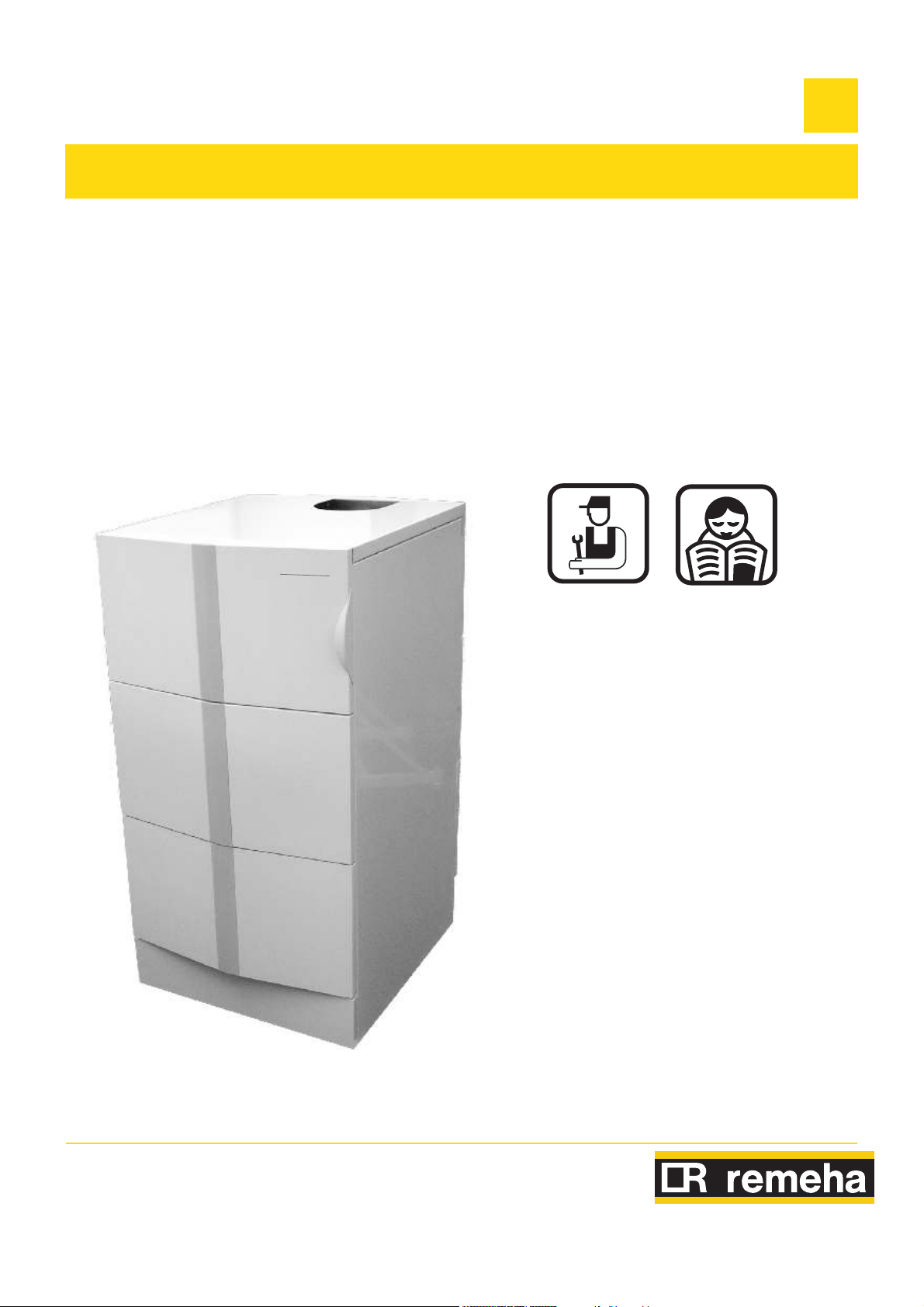
Remeha Gas 110 Eco
Gas fired condensing boiler
Gas 110 Eco 115/65
EN
Remeh a
Installation, User and
Service Manual
300014883-001-02
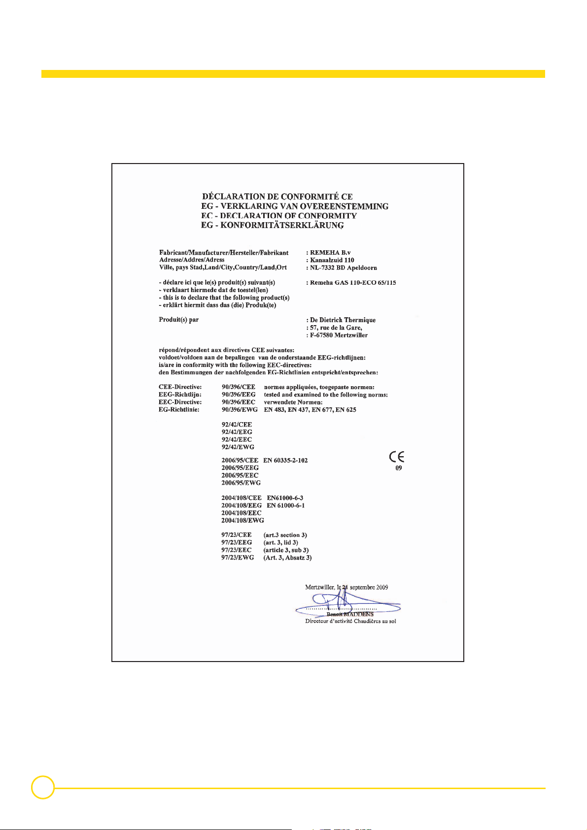
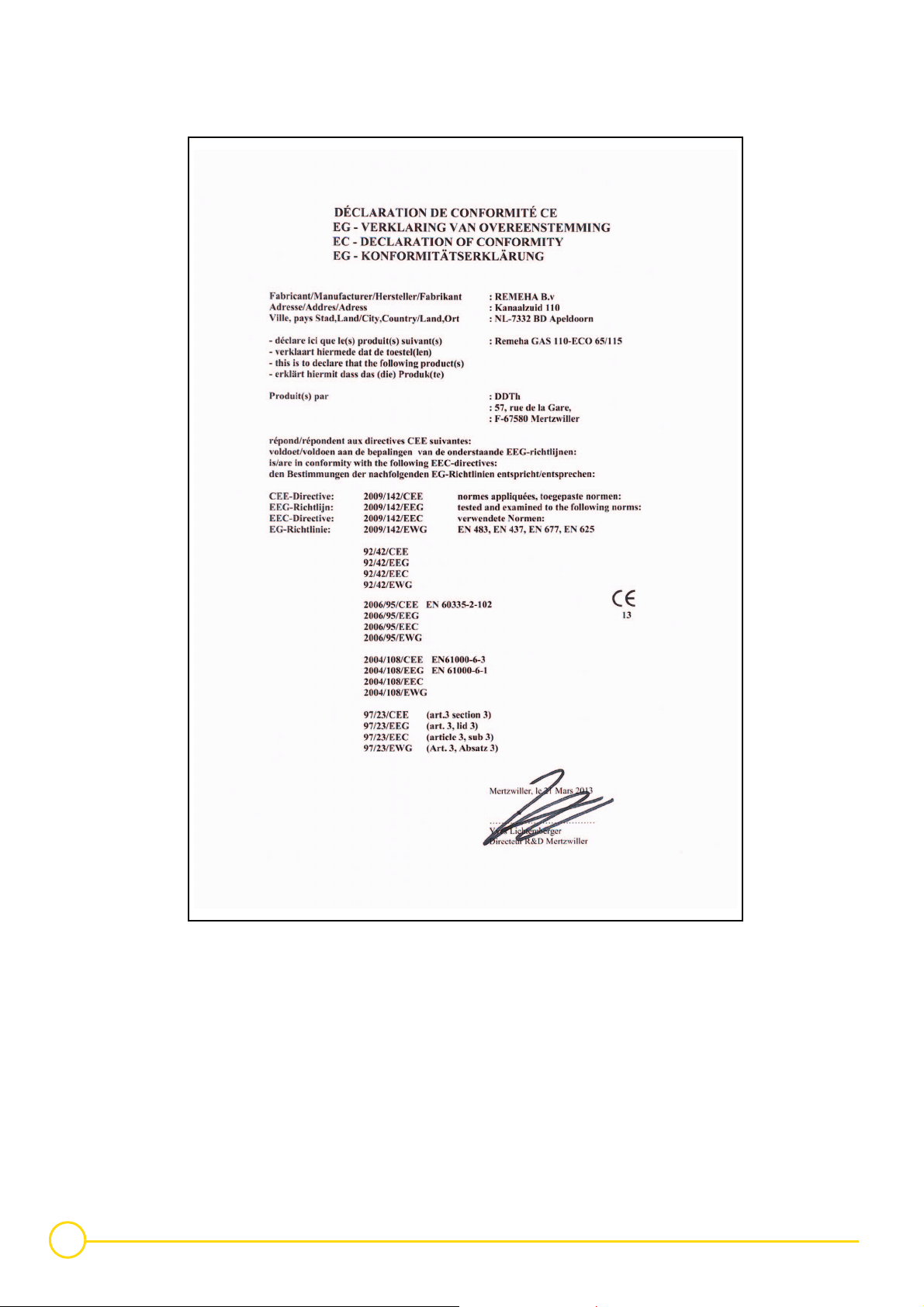
Declaration of conformity 1
The appliance complies with the standard model described in
declaration of compliance 1. It is manufactured and distributed
pursuant to the requirements of european directives. The original
declaration of conformity is available from the manufacturer.
C002718-B
2
Gas 110 Eco 115/65 18/06/2015 - 300014883-001-02

Contents
1 Safety instructions . . . . . . . . . . . . . . . . . . . . . . . . . . . . . . . . . . . . . . . . . . . . . . . . . . . . . . . . . . . . . . . . . . . . . . .5
1.1 General safety instructions . . . . . . . . . . . . . . . . . . . . . . . . . . . . . . . . . . . . . . . . . . . . . . . . . . . . . . . . . . . . . . . . . . . . . . . . . . . . . . . . .5
1.1.1 Fire hazard. . . . . . . . . . . . . . . . . . . . . . . . . . . . . . . . . . . . . . . . . . . . . . . . . . . . . . . . . . . . . . . . . . . . . . . . . . . . . . . . . . . . . . .5
1.1.2 Risk of intoxication . . . . . . . . . . . . . . . . . . . . . . . . . . . . . . . . . . . . . . . . . . . . . . . . . . . . . . . . . . . . . . . . . . . . . . . . . . . . . . . . .5
1.1.3 Risk of being burnt . . . . . . . . . . . . . . . . . . . . . . . . . . . . . . . . . . . . . . . . . . . . . . . . . . . . . . . . . . . . . . . . . . . . . . . . . . . . . . . . .5
1.1.4 Risk of damage . . . . . . . . . . . . . . . . . . . . . . . . . . . . . . . . . . . . . . . . . . . . . . . . . . . . . . . . . . . . . . . . . . . . . . . . . . . . . . . . . . .5
1.2 Recommendations . . . . . . . . . . . . . . . . . . . . . . . . . . . . . . . . . . . . . . . . . . . . . . . . . . . . . . . . . . . . . . . . . . . . . . . . . . . . . . . . . . . . . . .5
1.3 Liabilities. . . . . . . . . . . . . . . . . . . . . . . . . . . . . . . . . . . . . . . . . . . . . . . . . . . . . . . . . . . . . . . . . . . . . . . . . . . . . . . . . . . . . . . . . . . . . . .6
1.3.1 Manufacturer's liability . . . . . . . . . . . . . . . . . . . . . . . . . . . . . . . . . . . . . . . . . . . . . . . . . . . . . . . . . . . . . . . . . . . . . . . . . . . . . . 6
1.3.2 Installer's liability . . . . . . . . . . . . . . . . . . . . . . . . . . . . . . . . . . . . . . . . . . . . . . . . . . . . . . . . . . . . . . . . . . . . . . . . . . . . . . . . . .6
2 About this manual . . . . . . . . . . . . . . . . . . . . . . . . . . . . . . . . . . . . . . . . . . . . . . . . . . . . . . . . . . . . . . . . . . . . . . . .7
2.1 Symbols used in the manual . . . . . . . . . . . . . . . . . . . . . . . . . . . . . . . . . . . . . . . . . . . . . . . . . . . . . . . . . . . . . . . . . . . . . . . . . . . . . . .7
2.2 Abbreviations . . . . . . . . . . . . . . . . . . . . . . . . . . . . . . . . . . . . . . . . . . . . . . . . . . . . . . . . . . . . . . . . . . . . . . . . . . . . . . . . . . . . . . . . . . .7
2.3 Homologations . . . . . . . . . . . . . . . . . . . . . . . . . . . . . . . . . . . . . . . . . . . . . . . . . . . . . . . . . . . . . . . . . . . . . . . . . . . . . . . . . . . . . . . . . .7
2.3.1 General instructions . . . . . . . . . . . . . . . . . . . . . . . . . . . . . . . . . . . . . . . . . . . . . . . . . . . . . . . . . . . . . . . . . . . . . . . . . . . . . . . .7
3 Description. . . . . . . . . . . . . . . . . . . . . . . . . . . . . . . . . . . . . . . . . . . . . . . . . . . . . . . . . . . . . . . . . . . . . . . . . . . . . .9
3.1 General. . . . . . . . . . . . . . . . . . . . . . . . . . . . . . . . . . . . . . . . . . . . . . . . . . . . . . . . . . . . . . . . . . . . . . . . . . . . . . . . . . . . . . . . . . . . . . . .9
3.2 General instructions . . . . . . . . . . . . . . . . . . . . . . . . . . . . . . . . . . . . . . . . . . . . . . . . . . . . . . . . . . . . . . . . . . . . . . . . . . . . . . . . . . . . . .9
3.2.1 Gas categories. . . . . . . . . . . . . . . . . . . . . . . . . . . . . . . . . . . . . . . . . . . . . . . . . . . . . . . . . . . . . . . . . . . . . . . . . . . . . . . . . . . .9
3.3 Main parts. . . . . . . . . . . . . . . . . . . . . . . . . . . . . . . . . . . . . . . . . . . . . . . . . . . . . . . . . . . . . . . . . . . . . . . . . . . . . . . . . . . . . . . . . . . . .10
3.4 Technical specifications . . . . . . . . . . . . . . . . . . . . . . . . . . . . . . . . . . . . . . . . . . . . . . . . . . . . . . . . . . . . . . . . . . . . . . . . . . . . . . . . . .12
3.4.1 Boiler . . . . . . . . . . . . . . . . . . . . . . . . . . . . . . . . . . . . . . . . . . . . . . . . . . . . . . . . . . . . . . . . . . . . . . . . . . . . . . . . . . . . . . . . . .12
3.4.2 Control panel . . . . . . . . . . . . . . . . . . . . . . . . . . . . . . . . . . . . . . . . . . . . . . . . . . . . . . . . . . . . . . . . . . . . . . . . . . . . . . . . . . . .12
3.5 Technical data . . . . . . . . . . . . . . . . . . . . . . . . . . . . . . . . . . . . . . . . . . . . . . . . . . . . . . . . . . . . . . . . . . . . . . . . . . . . . . . . . . . . . . . . .13
3.6 Main dimensions. . . . . . . . . . . . . . . . . . . . . . . . . . . . . . . . . . . . . . . . . . . . . . . . . . . . . . . . . . . . . . . . . . . . . . . . . . . . . . . . . . . . . . . .14
3.6.1 Boiler self-standing. . . . . . . . . . . . . . . . . . . . . . . . . . . . . . . . . . . . . . . . . . . . . . . . . . . . . . . . . . . . . . . . . . . . . . . . . . . . . . . .14
3.6.2 Boiler installed . . . . . . . . . . . . . . . . . . . . . . . . . . . . . . . . . . . . . . . . . . . . . . . . . . . . . . . . . . . . . . . . . . . . . . . . . . . . . . . . . . .15
3.7 Hydraulic specifications . . . . . . . . . . . . . . . . . . . . . . . . . . . . . . . . . . . . . . . . . . . . . . . . . . . . . . . . . . . . . . . . . . . . . . . . . . . . . . . . . .16
4 Control panel . . . . . . . . . . . . . . . . . . . . . . . . . . . . . . . . . . . . . . . . . . . . . . . . . . . . . . . . . . . . . . . . . . . . . . . . . . .17
4.1 General. . . . . . . . . . . . . . . . . . . . . . . . . . . . . . . . . . . . . . . . . . . . . . . . . . . . . . . . . . . . . . . . . . . . . . . . . . . . . . . . . . . . . . . . . . . . . . .17
4.1.1 Layout of the control panel. . . . . . . . . . . . . . . . . . . . . . . . . . . . . . . . . . . . . . . . . . . . . . . . . . . . . . . . . . . . . . . . . . . . . . . . . .17
4.1.2 Combined key functions (in operating mode only) . . . . . . . . . . . . . . . . . . . . . . . . . . . . . . . . . . . . . . . . . . . . . . . . . . . . . . . .17
4.1.3 Display of values with more than two digits . . . . . . . . . . . . . . . . . . . . . . . . . . . . . . . . . . . . . . . . . . . . . . . . . . . . . . . . . . . . .18
4.2 Flow diagram control system . . . . . . . . . . . . . . . . . . . . . . . . . . . . . . . . . . . . . . . . . . . . . . . . . . . . . . . . . . . . . . . . . . . . . . . . . . . . . .19
4.3 Operating mode (N>>) . . . . . . . . . . . . . . . . . . . . . . . . . . . . . . . . . . . . . . . . . . . . . . . . . . . . . . . . . . . . . . . . . . . . . . . . . . . . . . .20
4.4 Shut-off mode (B<<) . . . . . . . . . . . . . . . . . . . . . . . . . . . . . . . . . . . . . . . . . . . . . . . . . . . . . . . . . . . . . . . . . . . . . . . . . . . . . . . . .21
4.5 Setting mode user level (<>>). . . . . . . . . . . . . . . . . . . . . . . . . . . . . . . . . . . . . . . . . . . . . . . . . . . . . . . . . . . . . . . . . . . . . . . . . .21
4.5.1 Flow temperature set point (). . . . . . . . . . . . . . . . . . . . . . . . . . . . . . . . . . . . . . . . . . . . . . . . . . . . . . . . . . . . . . . . . . . . . .22
4.5.2 Pump run on time HTG ()) . . . . . . . . . . . . . . . . . . . . . . . . . . . . . . . . . . . . . . . . . . . . . . . . . . . . . . . . . . . . . . . . . . . . . . . .22
4.5.3 DHW temperature set-point ( ) . . . . . . . . . . . . . . . . . . . . . . . . . . . . . . . . . . . . . . . . . . . . . . . . . . . . . . . . . . . . . . . . . . . . .23
4.5.4 Boiler control setting (*). . . . . . . . . . . . . . . . . . . . . . . . . . . . . . . . . . . . . . . . . . . . . . . . . . . . . . . . . . . . . . . . . . . . . . . . . . .23
4.6 Setting mode service level (<) . . . . . . . . . . . . . . . . . . . . . . . . . . . . . . . . . . . . . . . . . . . . . . . . . . . . . . . . . . . . . . . . . . . . . . .24
4.6.1 Flow temperature set point during forced part load () . . . . . . . . . . . . . . . . . . . . . . . . . . . . . . . . . . . . . . . . . . . . . . . . . . .25
4.6.2 High limit thermostat () . . . . . . . . . . . . . . . . . . . . . . . . . . . . . . . . . . . . . . . . . . . . . . . . . . . . . . . . . . . . . . . . . . . . . . . . . .25
4.6.3 Fan speed at full load HTG (?) . . . . . . . . . . . . . . . . . . . . . . . . . . . . . . . . . . . . . . . . . . . . . . . . . . . . . . . . . . . . . . . . . . . . .25
4.6.4 Fan speed at part load (HTG and DHW - ) . . . . . . . . . . . . . . . . . . . . . . . . . . . . . . . . . . . . . . . . . . . . . . . . . . . . . . . . . . . 25
4.6.5 Starting point modulation () . . . . . . . . . . . . . . . . . . . . . . . . . . . . . . . . . . . . . . . . . . . . . . . . . . . . . . . . . . . . . . . . . . . . . . .25
4.6.6 Interface selection () . . . . . . . . . . . . . . . . . . . . . . . . . . . . . . . . . . . . . . . . . . . . . . . . . . . . . . . . . . . . . . . . . . . . . . . . . . . .25
4.6.7 DHW cut-in temperature (+) . . . . . . . . . . . . . . . . . . . . . . . . . . . . . . . . . . . . . . . . . . . . . . . . . . . . . . . . . . . . . . . . . . . . . . .26
4.6.8 Fan Speed at DHW full load (0). . . . . . . . . . . . . . . . . . . . . . . . . . . . . . . . . . . . . . . . . . . . . . . . . . . . . . . . . . . . . . . . . . . . .26
4.6.9 Forced part load time after start (HTG only - /). . . . . . . . . . . . . . . . . . . . . . . . . . . . . . . . . . . . . . . . . . . . . . . . . . . . . . . . .26
4.6.10 DHW control stop set point (2) . . . . . . . . . . . . . . . . . . . . . . . . . . . . . . . . . . . . . . . . . . . . . . . . . . . . . . . . . . . . . . . . . . . . .26
4.6.11 DHW control option (3) . . . . . . . . . . . . . . . . . . . . . . . . . . . . . . . . . . . . . . . . . . . . . . . . . . . . . . . . . . . . . . . . . . . . . . . . . . .26
18/06/2015 - 300014883-001-02 Gas 110 Eco 115/65
3

4.6.12 HTG cut in temp (5). . . . . . . . . . . . . . . . . . . . . . . . . . . . . . . . . . . . . . . . . . . . . . . . . . . . . . . . . . . . . . . . . . . . . . . . . . . . . .26
4.6.13 Boiler type (7) . . . . . . . . . . . . . . . . . . . . . . . . . . . . . . . . . . . . . . . . . . . . . . . . . . . . . . . . . . . . . . . . . . . . . . . . . . . . . . . . . .26
4.6.14 Maximum delay time (;) . . . . . . . . . . . . . . . . . . . . . . . . . . . . . . . . . . . . . . . . . . . . . . . . . . . . . . . . . . . . . . . . . . . . . . . . . .27
4.6.15 Start and end point analog signal ( and =) . . . . . . . . . . . . . . . . . . . . . . . . . . . . . . . . . . . . . . . . . . . . . . . . . . . . . . . . . .27
4.7 Read-out mode (<) . . . . . . . . . . . . . . . . . . . . . . . . . . . . . . . . . . . . . . . . . . . . . . . . . . . . . . . . . . . . . . . . . . . . . . . . . . . . . . . .28
4.8 Fan speed mode (') . . . . . . . . . . . . . . . . . . . . . . . . . . . . . . . . . . . . . . . . . . . . . . . . . . . . . . . . . . . . . . . . . . . . . . . . . . . . . . .28
4.9 Failure mode (N) . . . . . . . . . . . . . . . . . . . . . . . . . . . . . . . . . . . . . . . . . . . . . . . . . . . . . . . . . . . . . . . . . . . . . . . . . . . . . . . . . .28
5 Installation . . . . . . . . . . . . . . . . . . . . . . . . . . . . . . . . . . . . . . . . . . . . . . . . . . . . . . . . . . . . . . . . . . . . . . . . . . . . .29
5.1 Statutory terms and conditions of installation and maintenance. . . . . . . . . . . . . . . . . . . . . . . . . . . . . . . . . . . . . . . . . . . . . . . . . . . .29
5.2 Important comments on the treatment of the heating circuit. . . . . . . . . . . . . . . . . . . . . . . . . . . . . . . . . . . . . . . . . . . . . . . . . . . . . . .30
5.3 Water discharge connection . . . . . . . . . . . . . . . . . . . . . . . . . . . . . . . . . . . . . . . . . . . . . . . . . . . . . . . . . . . . . . . . . . . . . . . . . . . . . . .32
5.4 Room sealed installations. . . . . . . . . . . . . . . . . . . . . . . . . . . . . . . . . . . . . . . . . . . . . . . . . . . . . . . . . . . . . . . . . . . . . . . . . . . . . . . . .32
5.5 Checking the gas inlet (Boiler only) . . . . . . . . . . . . . . . . . . . . . . . . . . . . . . . . . . . . . . . . . . . . . . . . . . . . . . . . . . . . . . . . . . . . . . . . .32
5.6 Reversal of the direction the control panel access door opens . . . . . . . . . . . . . . . . . . . . . . . . . . . . . . . . . . . . . . . . . . . . . . . . . . . .33
5.7 Levelling . . . . . . . . . . . . . . . . . . . . . . . . . . . . . . . . . . . . . . . . . . . . . . . . . . . . . . . . . . . . . . . . . . . . . . . . . . . . . . . . . . . . . . . . . . . . . .35
5.8 Handling the boiler . . . . . . . . . . . . . . . . . . . . . . . . . . . . . . . . . . . . . . . . . . . . . . . . . . . . . . . . . . . . . . . . . . . . . . . . . . . . . . . . . . . . . .35
6 Connecting the flue . . . . . . . . . . . . . . . . . . . . . . . . . . . . . . . . . . . . . . . . . . . . . . . . . . . . . . . . . . . . . . . . . . . . . .36
6.1 Flue pipe connections. . . . . . . . . . . . . . . . . . . . . . . . . . . . . . . . . . . . . . . . . . . . . . . . . . . . . . . . . . . . . . . . . . . . . . . . . . . . . . . . . . . .36
6.1.1 Classification . . . . . . . . . . . . . . . . . . . . . . . . . . . . . . . . . . . . . . . . . . . . . . . . . . . . . . . . . . . . . . . . . . . . . . . . . . . . . . . . . . . .37
6.1.2 Lengths of the air/flue gas pipes . . . . . . . . . . . . . . . . . . . . . . . . . . . . . . . . . . . . . . . . . . . . . . . . . . . . . . . . . . . . . . . . . . . . .38
6.2 Electrical connection. . . . . . . . . . . . . . . . . . . . . . . . . . . . . . . . . . . . . . . . . . . . . . . . . . . . . . . . . . . . . . . . . . . . . . . . . . . . . . . . . . . . .39
7 Commissioning . . . . . . . . . . . . . . . . . . . . . . . . . . . . . . . . . . . . . . . . . . . . . . . . . . . . . . . . . . . . . . . . . . . . . . . . .41
7.1 Filling the system . . . . . . . . . . . . . . . . . . . . . . . . . . . . . . . . . . . . . . . . . . . . . . . . . . . . . . . . . . . . . . . . . . . . . . . . . . . . . . . . . . . . . . .41
7.2 Check points before commissioning. . . . . . . . . . . . . . . . . . . . . . . . . . . . . . . . . . . . . . . . . . . . . . . . . . . . . . . . . . . . . . . . . . . . . . . . .41
7.2.1 Checking the gas supply pressure . . . . . . . . . . . . . . . . . . . . . . . . . . . . . . . . . . . . . . . . . . . . . . . . . . . . . . . . . . . . . . . . . . . .41
7.3 Putting the appliance into operation . . . . . . . . . . . . . . . . . . . . . . . . . . . . . . . . . . . . . . . . . . . . . . . . . . . . . . . . . . . . . . . . . . . . . . . . .42
7.3.1 Gas 110 Eco 65 . . . . . . . . . . . . . . . . . . . . . . . . . . . . . . . . . . . . . . . . . . . . . . . . . . . . . . . . . . . . . . . . . . . . . . . . . . . . . . . . . .43
7.3.2 Gas 110 Eco 115 . . . . . . . . . . . . . . . . . . . . . . . . . . . . . . . . . . . . . . . . . . . . . . . . . . . . . . . . . . . . . . . . . . . . . . . . . . . . . . . . .44
7.4 Programming boiler control . . . . . . . . . . . . . . . . . . . . . . . . . . . . . . . . . . . . . . . . . . . . . . . . . . . . . . . . . . . . . . . . . . . . . . . . . . . . . . .45
7.5 Instruct the user of the boiler . . . . . . . . . . . . . . . . . . . . . . . . . . . . . . . . . . . . . . . . . . . . . . . . . . . . . . . . . . . . . . . . . . . . . . . . . . . . . .45
7.6 Shut-down . . . . . . . . . . . . . . . . . . . . . . . . . . . . . . . . . . . . . . . . . . . . . . . . . . . . . . . . . . . . . . . . . . . . . . . . . . . . . . . . . . . . . . . . . . . .45
8 Fault finding . . . . . . . . . . . . . . . . . . . . . . . . . . . . . . . . . . . . . . . . . . . . . . . . . . . . . . . . . . . . . . . . . . . . . . . . . . . .46
8.1 General (all installations) . . . . . . . . . . . . . . . . . . . . . . . . . . . . . . . . . . . . . . . . . . . . . . . . . . . . . . . . . . . . . . . . . . . . . . . . . . . . . . . . .46
8.2 Fault codes . . . . . . . . . . . . . . . . . . . . . . . . . . . . . . . . . . . . . . . . . . . . . . . . . . . . . . . . . . . . . . . . . . . . . . . . . . . . . . . . . . . . . . . . . . . .47
9 Adapting to another gas type. . . . . . . . . . . . . . . . . . . . . . . . . . . . . . . . . . . . . . . . . . . . . . . . . . . . . . . . . . . . . .49
9.1 Switching from Natural Gas to Propane . . . . . . . . . . . . . . . . . . . . . . . . . . . . . . . . . . . . . . . . . . . . . . . . . . . . . . . . . . . . . . . . . . . . . .49
9.2 Gas type . . . . . . . . . . . . . . . . . . . . . . . . . . . . . . . . . . . . . . . . . . . . . . . . . . . . . . . . . . . . . . . . . . . . . . . . . . . . . . . . . . . . . . . . . . . . . .50
10 Maintenance. . . . . . . . . . . . . . . . . . . . . . . . . . . . . . . . . . . . . . . . . . . . . . . . . . . . . . . . . . . . . . . . . . . . . . . . . . . .51
10.1 General. . . . . . . . . . . . . . . . . . . . . . . . . . . . . . . . . . . . . . . . . . . . . . . . . . . . . . . . . . . . . . . . . . . . . . . . . . . . . . . . . . . . . . . . . . . . . . .51
10.2 Inspection . . . . . . . . . . . . . . . . . . . . . . . . . . . . . . . . . . . . . . . . . . . . . . . . . . . . . . . . . . . . . . . . . . . . . . . . . . . . . . . . . . . . . . . . . . . . .51
10.2.1 Checking the combustion in the boiler . . . . . . . . . . . . . . . . . . . . . . . . . . . . . . . . . . . . . . . . . . . . . . . . . . . . . . . . . . . . . . . . .51
10.2.2 Setting the ignition electrode . . . . . . . . . . . . . . . . . . . . . . . . . . . . . . . . . . . . . . . . . . . . . . . . . . . . . . . . . . . . . . . . . . . . . . . .52
10.2.3 Checking the hydraulic pressure . . . . . . . . . . . . . . . . . . . . . . . . . . . . . . . . . . . . . . . . . . . . . . . . . . . . . . . . . . . . . . . . . . . . .52
10.2.4 Checking the ionization current . . . . . . . . . . . . . . . . . . . . . . . . . . . . . . . . . . . . . . . . . . . . . . . . . . . . . . . . . . . . . . . . . . . . . .52
10.3 Cleaning and maintenance. . . . . . . . . . . . . . . . . . . . . . . . . . . . . . . . . . . . . . . . . . . . . . . . . . . . . . . . . . . . . . . . . . . . . . . . . . . . . . . .53
10.4 Maintenance of the air/flue gas drain connection flues . . . . . . . . . . . . . . . . . . . . . . . . . . . . . . . . . . . . . . . . . . . . . . . . . . . . . . . . . .56
10.5 Temperature sensor . . . . . . . . . . . . . . . . . . . . . . . . . . . . . . . . . . . . . . . . . . . . . . . . . . . . . . . . . . . . . . . . . . . . . . . . . . . . . . . . . . . . .56
11 Schematic diagrams . . . . . . . . . . . . . . . . . . . . . . . . . . . . . . . . . . . . . . . . . . . . . . . . . . . . . . . . . . . . . . . . . . . . .57
12 Spare parts - Gas 110 Eco 115/65 . . . . . . . . . . . . . . . . . . . . . . . . . . . . . . . . . . . . . . . . . . . . . . . . . . . . . . . . . .59
13 Appendix - Information on the Ecodesign and Energy Labelling Directives. . . . . . . . . . . . . . . . . . . . . . . .65
4
Gas 110 Eco 115/65 18/06/2015 - 300014883-001-02

1 Safety instructions
Danger
This appliance can be used by children aged
from 8 years and above and persons with
reduced physical, sensory or mental capabilities
or lack of experience and knowledge if they have
been given supervision or instruction
concerning use of the appliance in a safe way
and understand the hazards involved. Children
shall not play with the appliance. Cleaning and
user maintenance shall not be made by children
without supervision.
1.1 General safety instructions
1.1.1 Fire hazard
Do not stock products of an inflammable nature
close to the appliance.
If you smell gas, do not use a naked flame, do not
smoke, do not operate electrical contacts or
switches (doorbell, lights, motor, lift, etc.).
Any operation on the installation must be
performed by a qualified technician respecting
professional regulations and in accordance with
this document.
Before any work, switch off the mains supply to
the appliance. Protect the installation against
any unwanted restarts.
1.Shut off the gas supply
2.Open the windows
3.Extinguish all flames
4.Evacuate the premises
5.Contact a qualified professional
6.Inform the gas supplier
1.1.2 Risk of intoxication
Do not obstruct the air inlets in the room (even
partially).
If you smell flue gases
1.1.3 Risk of being burnt
Depending on the settings of the appliance:
- The temperature of the flue gas conduits may exceed
60°C
1.1.4 Risk of damage
Do not stock chloride or fluoride compounds
close to the appliance.
Install the appliance in frost-free premises.
1.2 Recommendations
1. Switch the appliance off
2. Open the windows
3. Evacuate the premises
4. Contact a qualified professional
- The temperature of the radiators may reach 95°C
- The temperature of the domestic hot water may reach
65°C
Do not neglect to service the appliance: Contact a
qualified professional or take out a maintenance contract
for the annual servicing of the appliance.
For a proper operating of the boiler, follow
carefully the instructions.
18/06/2015 - 300014883-001-02 Gas 110 Eco 115/65
Any intervention on the appliance and heating
equipment must be carried out by a qualified
engineer.
5

The manufacturer is not liable for any improper
use of the appliance or failure to maintain or
install the unit correctly (the user shall take care
to ensure that the system is installed by a
qualified engineer).
Work on electrical equipment must be carried out
by a qualified professional in compliance with
the prevailing regulations.
1.3 Liabilities
1.3.1 Manufacturer's liability
Check that the appliance is properly set for the
type of gas used.
Keep to the polarity shown on the terminals:
phase (L), neutral (N) and earth 4.
Check the seal on the gas and water pipe
connections.
We shall not accept any responsibility for any
damage and disturbance arising from not
following these instructions.
Our products are manufactured in compliance with the
requirements of the various applicable European
Directives. They are therefore delivered with CE marking
and all relevant documentation. In the interest of
customers, we are continuously endeavouring to make
improvements in product quality. All the specifications
stated in this document are therefore subject to change
without notice.
1.3.2 Installer's liability
The installer is responsible for the installation and
commissioning of the appliance. The installer is required
to observe the following instructions:
- Read and follow the instructions given in the manuals
provided with the appliance
- Install the appliance in acordance with the legislation
and standards currently in force
- Perform the initial start up and carry out any checks
necessary
- Explain the installation to the user
- If a maintenance is necessary, warn the user of the
obligation to check the appliance and maintain it in
good working order
- Give all the instruction manuals to the user
Our liability as the manufacturer may not be invoked in
the following cases:
- Failure to abide by the instructions on installing the
appliance
- Failure to abide by the instructions on using the
appliance
- Faulty or insufficient maintenance of the appliance
6
Gas 110 Eco 115/65 18/06/2015 - 300014883-001-02

2 About this manual
2.1 Symbols used in the manual
Caution danger
Risk of injury and damage to equipment. Attention must be
paid to the warnings on safety of persons and equipment.
Specific information
Information must be kept in mind to maintain comfort.
2.2 Abbreviations
` DHW: Domestic hot water.
` PPS: Polypropylene hardly inflammable.
` 3CE: Collective conduit for sealed boiler
2.3 Homologations
2.3.1 General instructions
Installation must be carried out in accordance with the prevailing
regulations, the codes of practice and the recommendations in these
instructions.
The first start-up is to be performed by your installation/
commissioning engineer.
Only original spare parts must be used.
Any work on the gas valve unit is authorised only if carried out by a
qualified professional. Please confirm to the user of the installation
that you have carried out a leak tightness check on the gas circuit.
In application of Article 25 of the Order of 27 April 2009 amending the
Order of 2 August 1977 amended and Article 1 of the amended Order
of 05/02/1999, the installer is required to draw up certificates of
conformity approved by the Ministers responsible for construction
and gas safety. Boilers must be used only with the types of gas
indicated on the rating plate.
Before commissioning, the factory settings of the appliance must be
compared with the local energy supply conditions. If the settings have
to be modified, this must be carried out by a qualified professional.
Condensing boilers require a flue gas discharge system or a fresh air
inlet specially adapted to the method of operation. Its execution
depends on the place of installation and the building.
Compliance with a minimum distance between the flue gas discharge
system in forced flue mode or the boiler with combustible substances
is not necessary. At nominal output, the temperature of the
components does not exceed 85 °C.
Work on electrical equipment must be carried out by a
qualified professional in compliance with the prevailing
regulations.
Reference
Z
Refer to another manual or other pages in this instruction
manual.
Hi: Lower heating value LHV (Nett)
Hs: Higher heating value HHV (Gross)
Switzerland
SVGW No.: 08-008-4
The installation of the boiler must be done in compliance with the
following directives:
- SSIGE regulations - G1: Gas installation,
- VKF requirements (Cantonal Grouping of Insurance Brokers),
- Local and cantonal regulations.
Installation and maintenance of the boiler must be carried out by a
qualified professional in compliance with prevailing local and national
regulations.
The safety distance between combustible substances and the boiler
and gaseous effluents must comply with the requirements of the
AEAI standard.
Other countries
Installation and maintenance of the boiler must be carried out by a
qualified professional in compliance with prevailing local and national
regulations.
18/06/2015 - 300014883-001-02 Gas 110 Eco 115/65
7
M003123-B
8
Gas 110 Eco 115/65 18/06/2015 - 300014883-001-02
3 Description
3.1 General
Gas 100 Eco 115 / 65 boilers are floor standing gas-fired condensing
boilers fitted with an "Open Therm" control interface which enable
direct weather compensation using Remeha single and multi boilers
controls or the customer can choose to use external control options
supplied by others without affecting boiler performance.
They are designed for closed circuit hot water boiler rooms with a
maximum operating temperature of 90°C. However, open vented
systems can be accommodated.
3.2 General instructions
Boiler Gas 110 Eco 65 / Gas 110 Eco 115
No. CE CE-0063BS3826
Type
Flue gas discharge Chimney / Flue gas outlet
Ignition Automatic
Gas Natural gas / Propane
3.2.1 Gas categories
Category Type of gas used
Gas 110 Eco 65
Gas 110 Eco 115
II
2H3P
See chapter 5.2 "Important comments on the treatment of the
Z
heating circuit".
Installation is recommended on low temperature heating installations
(Underfloor heating, radiators, ...).
- C
B
Natural gas 40 mbar
Propane 60 mbar
- C33 - C43 - C53 - C63 - C
23p
13
Supply pressure (Gas pressure when the boiler
Maximum allowed on the gas valve
- C
83
93
is not operating)
Gas 110 Eco 65
Gas 110 Eco 115
Category Type of gas used
II
2H3P
Natural gas 17 mbar 25 mbar
Propane 25 mbar 57.5 mbar
Working pressure
Minimum Maximum
18/06/2015 - 300014883-001-02 Gas 110 Eco 115/65
9
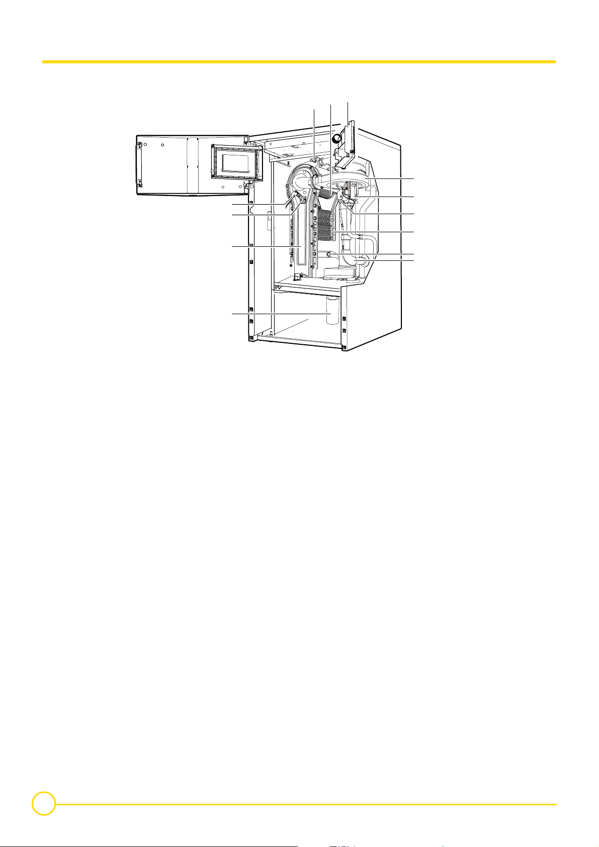
3.3 Main parts
• Gas 110 Eco 65
7
8
9
6
1 Fan air inlet
2 Return sensor
3 Heating body
4 Heat exchanger
5 Combined venturi and gas valve unit
6 Fan
7 Control panel
8 Burner
9 Flow temperature sensor
10 Ignition electrode + Ionization electrode
11 Sight glass
12 Front plate exchanger
13 Condensate trap
10
11
12
13
5
4
3
2
1
C001484
10
Gas 110 Eco 115/65 18/06/2015 - 300014883-001-02

• Gas 110 Eco 115
7
8
9
6
1 Fan air inlet
2 Return sensor
3 Heating body
4 Heat exchanger
5 Combined venturi and gas valve unit
6 Fan
7 Control panel
8 Burner
9 Flow temperature sensor
10 Ignition electrode + Ionization electrode
11 Sight glass
12 Front plate exchanger
13 Condensate trap
10
11
12
13
5
4
3
2
1
C001485
18/06/2015 - 300014883-001-02 Gas 110 Eco 115/65
11

3.4 Technical specifications
3.4.1 Boiler
- For operation on Natural Gas or Propane (See "Switching from
Natural Gas to Propane")
- The boiler is preset in the factory to operate on natural gas G20,
20 mbar (minimum 17 mbar)
- The boiler is suitable for room sealed or open flue applications
- Single-unit heat exchanger in aluminium/silicium alloy
- Cylindrical premix burner covered in metal fibres
3.4.2 Control panel
Please read the following installation and commissioning
instructions carefully before operating your equipment. The
manufacturer shall not be liable for damage caused by the
failure to comply with these instructions and the warranty shall
no longer apply.
If work is carried out on the heating installation: assembly,
commissioning, maintenance and repair work on the
appliance and on the heating installation must be carried
out only by a qualified heating professional.
Before installation: Ensure that the mains power supply is
isolated.
Before commissioning: Check the seal on the gas and
water pipe connections.
- Centrifugal fan with combustive air intake silencer for a low noise
level
- Compact gas line with zero pressure regulator, two valves and filter
- Water condensation siphon with run-off pipe
- Automatic air vent
- Mechanical manometer
- Soundproofed boiler body
- A documentation pack.
The connection of the control panel must be carried out by
a qualified professional. For a proper operating of the
boiler, follow carefully the instructions.
- Power supply: 230 V (±10%) - 50 Hz
12
Gas 110 Eco 115/65 18/06/2015 - 300014883-001-02
3.5 Technical data
Gas 110 Eco 65 115
CE identification no **** CE-0063BS3826
Boiler specifications
Power input (Hi) - minimum/maximum G20 kW 12.2 - 62.0 17.2 - 110.2
Power input (Hs) - minimum/maximum G20 kW 13.5 - 68.8 19.1 - 122.3
Nominal output 50/30 °C - minimum/maximum G20 kW 13.3 - 65.0 18.4 - 114.0
Nominal output 80/60 °C - minimum/maximum G20 kW 12.0 - 61.0 16.6 - 107.0
Gas flow rate at nominal output (15 °C - 1013 mbar)
Natural gas G20
Propane
Efficiency 75/60 °C (DIN 4702 T8) (Hi) % 106 106
Efficiency 75/60 °C (DIN 4702 T8) (Hs) % 95.5 95.5
Efficiency 40/30 °C (DIN 4702 T8) (Hi) % 111 102.5
Efficiency 40/30 °C (DIN 4702 T8) (Hs) % 100 92.4
Load and water temperature efficiency
(-100% Pn-Average temperature 70 °C) (Hi)
Load and water temperature efficiency
(-100% Pn-Average temperature 70 °C) (Hs)
Load and water temperature efficiency
(-30% Pn-Return temperature 30 °C) (Hi)
Load and water temperature efficiency
(-30% Pn-Return temperature 30 °C) (Hs)
Stand-by losses ∆T = 30K W 125 131
Mass flue gas flow rate - minimum/maximum Kg/h 20.5/104 28.9/186
level in flue gases
CO
2
- Natural gas G20
- Propane
Available pressure at boiler outlet Pa 100 250
Average flue gas temperature (75/60 °C) °C 65 67.9
Connection to a chimney (internal diameter) mm 100/150 100/150
Emission NOx (Natural gas G20) - dry 0% O
2
Emission CO (Natural gas G20) - DIN 4702 Teil 8 mg/kWh 21 31 (EN297A3)
NOx classification 55
Maximum operating temperature °C 90 90
Maximum operating pressure bar (MPa) 4 4
Water resistance (∆T = 20K) mbar 175 230
Water resistance (∆T = 11K) mbar 580 830
Nominal water flow Pn to ∆T = 20K
Nominal water flow Pn to ∆T = 11K
Water content
Flow and return connection (diameter) 1" 1/4 Male 1" 1/4 Male
Condensation water pH 3-5 3-5
Condensation water run-off (diameter) mm 25 25
Electrical specifications
Electrical connection V/Hz 230/50 230/50
Power consumption W 88 213
Protection rating DIN40050 IP 21 IP 21
Dimensions
Height mm 1100 1322
Width mm 600 600
Depth mm 663 663
Shipping weight kg 116 133
3
m
Kg/h
/h
6.56
4.82
11.66
8.56
%98.3 97.1
%88.6 87.5
% 108.9 107.1
%98.1 96.5
%
%
9.0
10.7
9.5
10.0
mg/kWh 32 35
3
m
/h
3
/h
m
l
2.62 4.6
4.76 8.36
6.5 7.5
18/06/2015 - 300014883-001-02 Gas 110 Eco 115/65
13

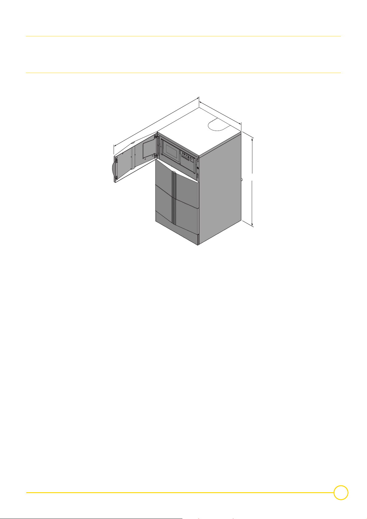
3.6 Main dimensions
3.6.1 Boiler self-standing
• Gas 110 Eco 115/65
600
A
770
663
ØF
8
1
170
D
9
208
21
C001272
460
1 Heating flow R 1 1/4 m
6 Heating return R 1 1/4 m
7 Condensates discharge (Ø 25 mm external)
8 Automatic air vent
9 Gas inlet R 3/4
Gas 110 Eco 65: 1100 mm
A
Gas 110 Eco 115: 1322 mm
Gas 110 Eco 65: 410 mm
B
Gas 110 Eco 115: 632 mm
Gas 110 Eco 65: 124 mm
C
Gas 110 Eco 115: 346 mm
Gas 110 Eco 65: 968 mm
D
Gas 110 Eco 115: 1190 mm
Gas 110 Eco 65: 152 mm
E
Gas 110 Eco 115: 374 mm
ØF Forced flue connection Ø 100/150 mm
B
6
C
7
E
198420
173
158
118
R = Thread
G = Exterior cylindrical threading, sealed by sheet gasket
(1) Basic dimension 21 mm
adjustment possible: 21 to 40 mm
14
Gas 110 Eco 115/65 18/06/2015 - 300014883-001-02
3.6.2 Boiler installed
Clear space should be left around the boiler:
- 70 cm in front of the boiler
- 40 cm above the boiler
• Gas 110 Eco 115/65
- 2.5 cm each side of the boiler
(Facilitates removal of the casing)
600
1263
A
C001486
A. Gas 110 Eco 65 = 1100
Gas 110 Eco 115 = 1322
18/06/2015 - 300014883-001-02 Gas 110 Eco 115/65
15
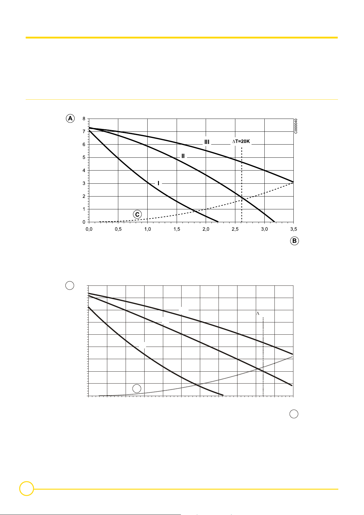
3.7 Hydraulic specifications
Depending on the flow, the following diagrams represent:
- the manometric heights of the heating
- loss of load in the boiler.
For a fixed flow, the manometric height available at the boiler outlet
is obtained by taking the difference between the manometric height
of the circulator pump and the loss of load in the boiler.
Optional 3-speed circulator pump for Gas 110 Eco 65 - UPS 25-70 130
For example: Gas 110 Eco 65 with UPS 25-70 130 pump:
manometric height available at 2.61 m
3
/h = 4.6 mWG - 1.6 mWG = 3
mWG (i.e. 3 mbar)
3
2.61 m
/h corresponds to a load of 61 kW and a ∆t of 20 K
A. Manometric height (mWG)
B. Flow rate (m
3
/h)
C. Loss of load Gas 110 Eco 65
Optional 3-speed circulator pump for Gas 110 Eco 115 - UPS 25-80 130
9
A
8
7
6
5
4
3
2
1
I
III
II
C
0
0,0 0,5 1,0 1,5 2,0 2,5 3,0 3,5 4,0 4,5 5,0 5,5
A. Manometric height (mWG)
3
B. Flow rate (m
/h)
C. Loss of load Gas 110 Eco 115
C001242
T=20K
B
16
Gas 110 Eco 115/65 18/06/2015 - 300014883-001-02
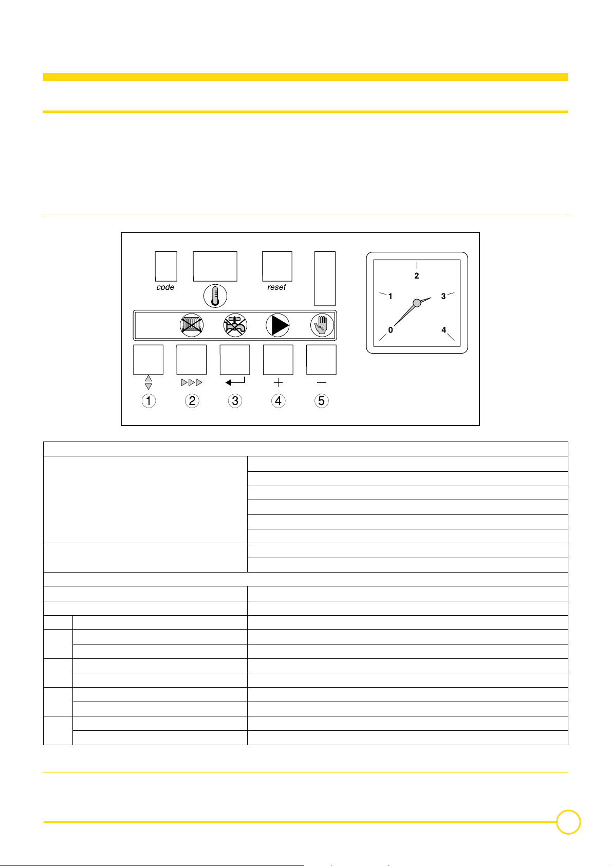
4 Control panel
4.1 General
The boiler is supplied with a standard set of defaults pre-programmed
for normal operation but can be tailored by the Engineer to suit most
site conditions. These values are set and read using the built in
control panel or with a notebook computer (with an interface and
software available on request).
4.1.1 Layout of the control panel
For security the control has three levels of access:
- User level - free access
- Service level - access with service code by qualified personnel
- Factory level - access by PC with factory code (Remeha only).
00.W4H.79.00044-B
code-display
Indicates on user level:
Additional indication on service level: Fan speed mode: alternate half digit '
x-display
Indicates: Temperatures, settings, fault codes (flashing digits), shut-off codes (flashing dots)
reset-key: To reset after a lockout condition
Key "r": Program function: key to select the required mode
Key "w": Program function: key to select the required program within the selected mode
Key w + Symbol v: Switch function: burner switch HTG (manual override)
Key "l": Program function: key to save the settings
Key "l" + Symbol q Switch function: burner switch DHW (manual override)
Key [+]: Program function: to select a higher setting
Key [+] + Symbol u Switch function: pump manual override
Key [-]: Program function: to select a lower setting
Key [-] + Symbol n: Switch function: manual override (hand/auto)
Operating mode: only one digit
Setting mode: digit with dot
Read-out mode: digit with flashing dot
Shut-off mode: letter B
Forced full load: letter G
Forced part load: letter H
Failure mode: flashing digit
4.1.2 Combined key functions (in operating mode only)
When the boiler is in the operating mode, keys with the illuminated symbols above have a double function (Program and Switch).
18/06/2015 - 300014883-001-02 Gas 110 Eco 115/65
17

To use them for a Program function press the key once - and for a
Switch function (either on or off) press the key and hold for
5 seconds.
The status of the switch function will be confirmed by the illuminated
symbol as follows:
• Key
"w" and symbol v:
- (symbol) not illuminated: HTG under normal control
- red (symbol) on: HTG off (manual override)
• Key
"l" and symbol q:
- (symbol) not illuminated: DHW under normal control
- red (symbol) on: DHW off (manual override)
• Key
[+] and symbol u:
- green (symbol) on: continuous pump operation
- (symbol) not illuminated: pump under boiler control
• Key
[-] and symbol n:
- green (symbol) on: HTG on (manual override)
- (symbol) not illuminated: HTG under normal control.
Manual override will stay active until deactivated, even if power is
switched off and then restored.
4.1.3 Display of values with more than two digits
NOTE: In the Switch function, (in order to protect the boiler and the
installation) the flow temperature cannot exceed it’s pre-set
maximum. It is also not possible to change any parameters.
• Forced mode "high" (G>>)
By pressing the keys
"r" and [+] simultaneously in operating mode,
the boiler will burn at maximum power. The letter G will now appear
on the display.
By pressing the keys
[+] and [-] simultaneously, the boiler will return
to operating mode. Following a manual override the boiler will return
to normal (auto control) if no keys are used within a 15 minute period.
• Forced mode "low" (H>>)
By pressing the keys
"r" and [-] simultaneously in operating mode,
the boiler will burn at minimum power. The letter H will now appear
on the display. By pressing the keys
[+] and [-] simultaneously, the
boiler will return to operating mode. Following a manual override the
boiler will return to normal (auto control) if no keys are used within a
15 minute period.
The display has only two digits available therefore values over this
are displayed as follows:
- negative values will be indicated by a dot behind the last digit e.g.
= -10
- values from 00 to 99 will be indicated without any punctuation
marks
- values from 100 to 199 will be indicated by a dot between both
digits e.g. = 100, = 110, & = 199.
- values from 200 to 299 will be indicated by a dot behind every digit
e.g. = for 200, = 210, = 299.
18
Gas 110 Eco 115/65 18/06/2015 - 300014883-001-02
4.2 Flow diagram control system
Press the "r"-key for the menu Press the "w"-key for the menu
code-display x-display
Operating mode
§ 4.3
Z
Setting mode, user level
§ 4.5
Z
Setting mode, service level
§ 4.6
Z
Only digit or letter
- &,G,H,B
Digit or letter with fixed dot
)
*
M
Flow temperature or shut-off code
Flow temperature set-point
Pump run on time HTG
DHW temperature set-point
Boiler control setting
Base point internal compensation slope
Service engineer level only:
?
+
0
.
/
1
Flow temperature set-point during forced part load
High limit temperature set-point
Fan speed at full load (HTG)
Fan speed at part load (HTG and DHW)
Modulation start point ∆T (F/R)
Interface selection (control option)
DHW cut-in ∆T
Fan speed at full load (DHW)
Intern
N/a
N/a
Forced part load time after start (HTG)
Fan speed at start
2 DHW control stop or boiler modulation set point (based on parameter )
3
4
5
6
7
;
8
=
@
DHW control mode
N/a
HTG cut-in ∆T (based on return)
N/a
Boiler type
Intern
Maximum delay time
Start point for 0 V analog signal
End point for 10 V analog signal
Intern
18/06/2015 - 300014883-001-02 Gas 110 Eco 115/65
19
Read-out mode
§ 4.7
Z
Service engineer level only:
Speed mode
§ 4.8
Z
Digit or letter with flashing dot
)
?
8
*
Alternate half digit ' Fan speed
Actual flow temperature
Actual return temperature
Actual DHW temperature (with sensor)
Actual outdoor temperature (only if outdoor sensor fitted)
N/a
Flow temperature (set point)
Actual heat demand status
Calculated HTG cut-in temperature
Actual flow temperature rise
N/a
Failure mode
§ 4.9
Z
Flashing digit
!
"
#
Failure code
Operating code during failure
Flow temperature during failure
Return temperature during failure
DHW temperature during failure
N/a
4.3 Operating mode (N>>)
During operation the "code"-display shows the status (position in
cycle) of the boiler, whilst the
temperature.
Code Description
Standby: there is no heat demand from control system
Ignition: ignition is activated for 2.4 seconds while the gas valve is opened
HTG mode: the boiler operates in the HTG mode
! DHW mode: the three way valve or DHW pump activated
" Internal check
# Normal control stop during HTG (flow temperature > set-point + 5 °C)
$ HTG pump run on
% DHW pump run on or for three way valve option, HTG pump run on with valve open to DHW (max. 5 minutes)
& Normal control stop during DHW (flow temperature > set point DHW + DHW control stop set point + 5 °C)
B Shut-off mode
G Forced full load
H Forced part load
Pre-purge: before start-up, the boiler is purged for 4.2 seconds
Post-purge: when the heat demand has been met, the fan continues to operate for another 10 seconds
x-display indicates the actual flow
The digits or letters in the code-display have the following meaning:
20
Gas 110 Eco 115/65 18/06/2015 - 300014883-001-02
4.4 Shut-off mode (B<<)
During shut-off mode condition the "code"-display will show a B,
whilst the
Code Description
B)
x-display indicates the cause with two flashing dots.
Maximum acceptable flow temperature rise exceeded. The boiler will shut off for ten minutes, then restart. Should the flow
Table below details cause of shut-off mode.
temperature conditions remain the same after 5 attempts, this code will be recorded as a shutdown failure. Boiler will not
lockout.
B)+
Contacts of the external interlock have opened during heat demand. The boiler will shut off for 120 seconds. Should the contacts close again during heat demand, the boiler will wait the remaining time from the 120 seconds before attempting a
restart.
B) Internal check on fan speed. After 5 attemps, the boiler will lockout. This code will be recorded.
B) Internal check on fan speed. After 5 attemps, the boiler will lockout. This code will be recorded.
B Maximum temperature difference between flow and return exceeded. The boiler will shut off for 150 seconds, then restart.
Should the temperature difference conditions remain the same after 10 attemps, this code will be recorded as a shut-down
failure. Boiler will not lockout.
B One or several adjusted parameters out of range including some factory defaults which should not have been changed.
Check and reset parameters:
- Press the "reset"-key immediately followed by pressing the "r"-key for about 12 seconds,
- code-display shows 7,
-use [+] and [-] -keys to enter correct boiler parameter
(7=! for Gas 110 Eco 115, 7=#! for Gas 110 Eco 65)
-press "l"-key to confirm settings,
- check parameter settings and change were needed or desired.
NOTE: Shut-off mode is a normal boiler operating function and does
not represent a boiler failure.
However, this may indicate a system problem, an internal boiler
check or an incorrect parameter setting.
4.5 Setting mode user level (<>>)
Code Description Setting range Preset
) Pump run on time HTG
*
;
NOTE: Changing code ) and code * should only be on design
engineers advice.
Flow temperature set point
-& °C %
= pump run on 10 seconds
-"= pump run on in minutes
DHW temperature set point
Boiler control setting Control mode (modulating-on/off etc.)
Base point internal compensation slope N/a
-$" °C (only with sensor) ""
18/06/2015 - 300014883-001-02 Gas 110 Eco 115/65
21
4.5.1 Flow temperature set point ()
The required flow temperature is adjustable from 20 to 90 °C.
4.5.2 Pump run on time HTG ())
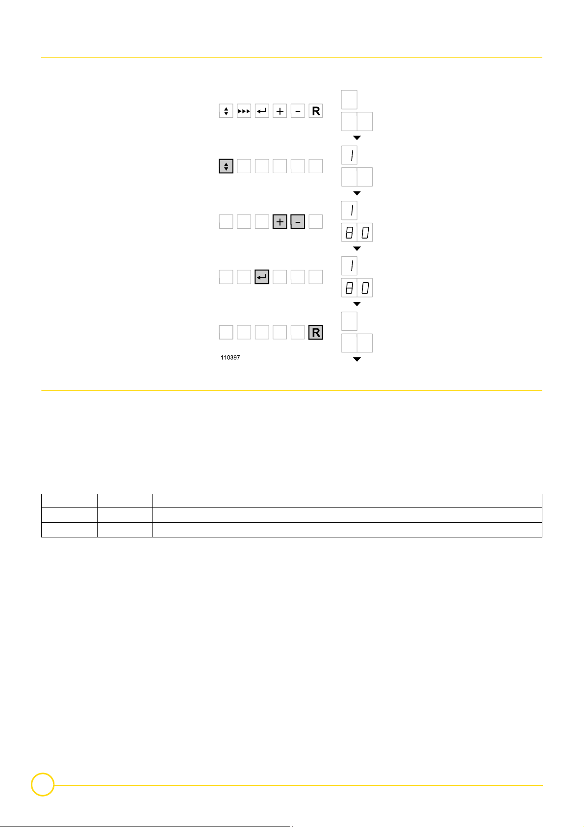
Pump run on time can be adjusted (Please refer to installation
contractor)
- Press the "r" -key until the digit (with dot) appears in the
"code"-display.
- Press the "w"-key until the digit ) (with dot) appears in the
"code"-display.
- Set the required value, using the [+] and [-] -keys.
Code x Description
)Pump runs on for 10 seconds
)<NPump runs on for 1 to 15 minutes (NN= to ")
- Press the "l"-key to store the new value (value will flash twice).
- Press the "reset"-key to return to operating mode.
NOTE: For continuous pump operation use manual override,
See chapter 4.1.3.
Z
22
Gas 110 Eco 115/65 18/06/2015 - 300014883-001-02
 Loading...