

REMEHA GAHP-A Installation, User And Maintenance Manual
Installation, user and
maintenance manual
GAHP-A
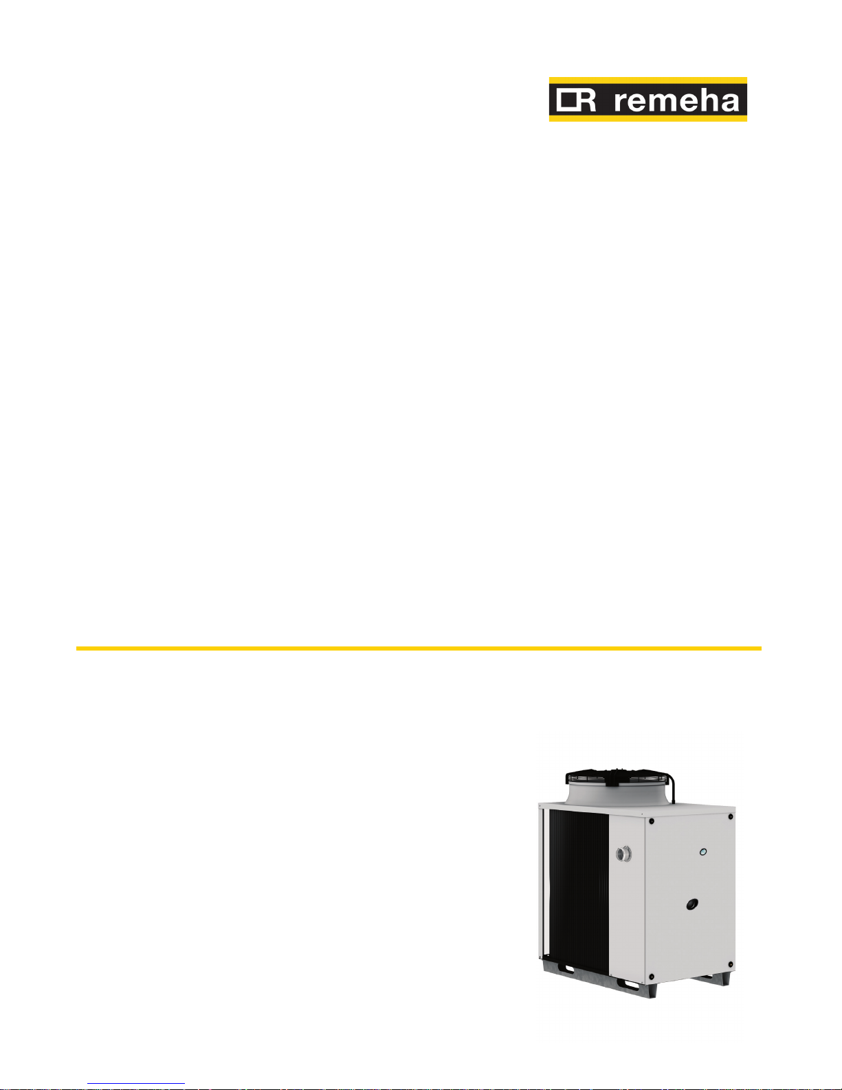
air-water gas absorption heat pump
powered by natural gas and renewable energy

Revision: A
Code: D-LBR637

Installation, user and maintenance manual – GAHP-A
3
INDEX OF CONTENTS
1 SAFETY AND SYMBOLS ...................................................................................4
1.1 SYMBOLS .......................................................................................................................................................................................... 4
1.2 SAFETY ..............................................................................................................................................................................................4
2 OVERVIEW AND TECHNICAL FEATURES ........................................................8
2.1 Conformity to CE standards ......................................................................................................................................................8
2.2 GENERAL FEATURES .....................................................................................................................................................................8
2.3 TECHNICAL DATA ..........................................................................................................................................................................9
2.4 DIMENSIONS .................................................................................................................................................................................13
2.5 ELECTRICAL DIAGRAM OF THE APPLIANCE .......................................................................................................................18
3 TRANSPORTATION AND POSITIONING .......................................................19
4 HYDRAULIC INSTALLATION ..........................................................................22
4.1 GENERAL INSTALLATION PRINCIPLES ..................................................................................................................................22
4.2 HYDRAULIC CONNECTIONS ....................................................................................................................................................23
4.3 GAS SUPPLY...................................................................................................................................................................................23
4.4 CONDENSATE DISCHARGE .......................................................................................................................................................24
4.5 WATER QUALITY...........................................................................................................................................................................25
4.6 FILLING OF HYDRAULIC CIRCUIT ...........................................................................................................................................28
4.7 EXHAUST FLUE GAS ....................................................................................................................................................................28
5 ELECTRICAL INSTALLATION ..........................................................................30
5.1 ELECTRICAL POWER SUPPLY ...................................................................................................................................................31
5.2 WIRING OF AN ON/OFF CIRCULATION PUMP ...................................................................................................................32
5.3 WIRING OF A MODULATING PUMP .......................................................................................................................................36
5.4 ON/OFF PERMISSIVE ..................................................................................................................................................................38
5.5 CAN BUS CABLE CONNECTION .............................................................................................................................................39
5.6 HOW TO RESET THE FLAME CONTROLLER FROM REMOTE ..........................................................................................43
6 COMMISSIONING AND FIRST START UP ......................................................46
6.1 PROCEDURE FOR FIRST START UP .........................................................................................................................................46
6.2 CHANGE OF GAS TYPE ..............................................................................................................................................................50
7 NORMAL OPERATION ....................................................................................52
7.1 SWITCHING ON AND OFF .........................................................................................................................................................52
7.2 ON-BOARD ELECTRONICS ........................................................................................................................................................52
7.3 OPERATING SETTINGS ...............................................................................................................................................................55
7.4 DISPLAYING AND RESETTING OPERATING CODES ..........................................................................................................57
7.5 RESET OPERATIONS ....................................................................................................................................................................57
7.6 MANUAL DI DEFROSTING ........................................................................................................................................................59
7.7 PROLONGED PERIODS OF DISUSE ........................................................................................................................................59
8 MAINTENANCE ...............................................................................................62
OPERATING CODES/TROUBLESHOOTING ...........................................................64
1 OVERVIEW AND OPERATING CODES/TROUBLESHOOTING ..........................................................................................64
ACCESSORIES .........................................................................................................66
APPENDIX ...............................................................................................................67
1 SAFETY DEVICES PRESCRIBED BY THE PED .......................................................................................................................67
2 ADDITIONAL SAFETY DEVICES ...............................................................................................................................................68
3 SAFETY VALVE REPLACEMENT OPERATIONS .....................................................................................................................69
4 NON-CONDENSABLE OR NON-ABSORBABLE GASES .....................................................................................................72

4
1 SAFETY AND SYMBOLS
This Installation, user and maintenance manual is a guide to the installation and operation of the Air-Water gas absorption heat pump "GAHP-A".
This manual is specifically intended for:
final users for the operation of the appliance according to their own •
requirements;
Installation technicians (hydraulic and electrical) for a correct installation of the •
appliance.
The manual also contains:
a section that describes all the operations necessary for the “first start-up” and for •
the “gas change” of the appliance, as well as the main maintenance operations;
an "ACCESSORIES" section with a description of accessories available and their re-•
spective reference codes.
Note on controllers
If the appliance is connected to a Comfort Control Panel (CCP), to a Comfort Control Interface (CCI) or to a Direct Digital Controller (DDC), please refer to the relevant manuals
for configuration and operation.
1.1 SYMBOLS
The icons in the edge of the manual have the following meanings:
= DANGER
= WARNING
= NOTE
= START OF OPERATING PROCEDURE
= REFERENCE to another part of the manual or other document
1.2 SAFETY
The appliance must only be used for the purposes for which it has been designed. Any
other use is considered inappropriate and therefore dangerous. The manufacturer does
not accept any contractual or extra-contractual liability for any damage caused by improper use of the appliance.
The appliance is not intended to be used by persons (including children) whose physical,
sensory and mental capacities are impaired, or who lack the necessary experience and
knowledge, unless they are supervised or instructed in its use by persons responsible
for their safety. Children must be supervised to ensure that they do not play with the
appliance.
Installation, user and maintenance manual – GAHP-A
5
The unit uses a water/ammonia absorption cycle for hot water production. The ammonia
is in water solution inside a sealed circuit tested for tightness by the manufacturer. In case
of refrigerant leaks, switch off the electrical power and gas supplies only if this can be
done in total safety. Contact your Technical Assistance.
Frequent topping up of the hydraulic with water can result in damage due to scale and
corrosion, depending on the quality of the water being used. Make sure the system is
water tight and that the expansion tank is operational.
Concentrations of chlorides or free chlorine in the circuit above the values given in Table
4.1 Chemical and physical parameters of water → 26 will damage the unit's water/ammonia exchanger.
Close the gas supply before working on the gas circuit. On completing work on the gas
circuit, check for leakages as required by established regulations.
Do not operate the appliance if dangerous conditions exist: odour of gas in the grid
or near the appliance; problems with the electrical/gas grid or hydraulic circuit; parts
of the appliance submerged in water or otherwise damaged; controls or safety components bypassed or defective. In these cases, ask for assistance to professionally qualified
personnel.
If you smell gas:
do not use electrical devices such as telephones, multimeters or other equipment •
that can cause sparks next to the appliance;
shut off gas supply closing the isolation valve;•
cut off electrical power opening the main breaker upstream of the appliance (to be •
provided by the electrical installer in an appropriate panel);
ask for assistance to professionally qualified personnel from a telephone distant •
from the appliance.
Moving parts, also during the appliance's start-up and shut-down cycles. Do not remove
guards. Make sure the appliance cannot be started up inadvertently.
POISONING HAZARD
Make sure the flue gas components are tight and compliant with established regulations.
After any intervention on these parts, check for tightness.
BURN HAZARD
The appliance contains numerous hot parts. Do not open up the appliance or touch the
fumes outlet pipe. If necessary, contact your Technical Assistance.

6
The appliance has a sealed circuit classified as pressure equipment, i.e. with internal pressure higher than atmospheric pressure. The fluids contained in the sealed circuits are
harmful if swallowed or inhaled, or if they come into contact with the skin. Do not carry
out any operation on the sealed circuit or on its valves.
ELECTROCUTION HAZARD
Use only approved components for the electrical connections, as specified by the •
manufacturer.
Disconnect the electrical power supply before working on the appliance's internal •
electrical equipment (electrical panel, motors, control board, etc.).
Make sure the appliance cannot be started up inadvertently.•
The electrical safety of the appliance is ensured only when it is correctly connected to an
efficient grounding system, compilant with current safety regulations.
DAMAGE DUE TO AGGRESSIVE SUBSTANCES IN THE AIR SUPPLY
Hydrocarbons containing chlorine and fluorine compounds, will increase corrosion. Make
sure the air supply is free of aggressive substances.
ACID CONDENSATE
Drain out the condensate produced during combustion as indicated in paragraph 4.4
CONDENSATE DISCHARGE → 24.
EXPLOSIVE/FLAMMABLE MATERIALS HAZARD
Do not use or store flammable materials (paper, solvents, paint, etc.) in the vicinity of the
appliance.
RECOMMENDATION. Stipulate a maintenance contract with an authorised specialist
contractor for the annual inspection of the appliance and maintenance when needed.
Maintenance and repairs may only be done by a contractor legally authorised to work on
gas appliances and equipment. Use only original spare parts.
Operation and maintenance of the appliance
During normal operation, do not switch off the appliance by cutting electrical power
supply. The appliance must be switched off by means of its controls; after switching off,
wait for the end of the cooling down cycle (about 7 minutes). The cooling down cycle
finishes when the oil pump stops (no component of the appliance is moving any more).
Shutting off the power supply while the appliance is running can cause permanent damages to internal components!
In the event of failure of the appliance and/or breakage of any component, do not attempt to repair and/or restore operation; proceed as follows:

Installation, user and maintenance manual – GAHP-A
7
shut off the appliance immediately (if possible and if no dangerous condition ex-•
ists) through the controls and wait for the end of the cooling down cycle (around
7 minutes);
immediately get in touch with Technical Assistance.•
Proper ordinary maintenance ensures the efficiency and good operation of the appliance over time.
Carry out maintenance operations according to the instructions supplied by the
manufacturer.
For the maintenance of internal components of the appliance, contact Technical Assistance or qualified technician; for other maintenance requirements, see Paragraph 8
MAINTENANCE → 62.
Any repair of the appliance must be carried out by Technical Assistance, using only original spare parts.
Failure to observe the indications above may compromise the operation and safety of the
appliance, and may invalidate warranty.
If the appliance is to be disposed of, contact the manufacturer for its correct disposal.
If the appliance is to be sold or transferred to another owner, ensure that this “Installation,
user and maintenance manual” is handed over to the new owner and installer.

8
2 OVERVIEW AND TECHNICAL FEATURES
In this section you will find general information, hints on the operating principle of the
appliance and its manufacturing features. This section also contains technical data and
dimensional drawings of the appliance.
2.1 CONFORMITY TO CE STANDARDS
This manual is an integral and essential part of the product and must be delivered to the
user together with the appliance.
The absorption heat pumps of the GAHP series are certified as conforming to standard EN
12309-1 and -2 and comply with the essential requirements of the following Directives:
Gas Directive 90/396/EEC and subsequent modifications and additions.•
Efficiency Directive 92/42/EEC and subsequent modifications and additions.•
Electromagnetic Compatibility Directive 89/336/EEC and subsequent modifica-•
tions and additions.
Low Voltage Directive 89/336/EEC and subsequent modifications and additions.•
Machinery Directive 2006/42/EC.•
Pressurised Equipment Directive 97/23/EEC and subsequent modifications and •
additions.
UNI EN 677 Specific requirements for condensing boilers with nominal thermal ca-•
pacity up to 70 kW.
EN 378 Refrigerating systems and heat pumps.•
The emission values of nitrogen oxides (NOx) of gas absorption heat pumps of the GAHP
series are lower than 60 mg/kWh, in compliance with the requirements of the standard
RAL UZ 118 "Blauer Engel".
2.2 GENERAL FEATURES
The appliance uses the water/ammonia absorption thermodynamic cycle (H20 – NH3) to
produce hot water, using atmospheric air as renewable energy source.
The water/ammonia thermodynamic cycle used in the unit GAHP-A is realized in a hermitically sealed circuit, directly verified by the manufacturer to ensure the perfect tightness of all joints, thus making refrigerant top-ups completely unnecessary.
The air-water gas absorption heat pump GAHP-A is available in the following versions:
Version • HT: optimised for high temperature distribution systems (radiators, fan
coils); it produces hot water up to +65°C in heating mode and up to +70°C in Domestic Hot Water mode.
Version • LT: optimised for low temperature distribution systems (heating floor, low
temperature radiators); it produces hot water up to +55°C in heating mode and up
to +70°C in Domestic Hot Water mode.
The appliance is supplied with the following technical manufacturing characteristics,
control and safety components.
Manufacturing features
Steel sealed circuit, externally treated with epoxy paint.•
Sealed combustion chamber suited for type C installation.•
Metal mesh radiant burner equipped with ignition electrodes and flame detection •
managed by an electronic flame control box.
Titanium stainless steel shall-and-tube heat exchanger, with external insulation.•
Recovery heat exchanger (AISI 304L).•

Installation, user and maintenance manual – GAHP-A
9
Air heat exchanger with single-row finned coil, manufactured with steel pipes and •
aluminium fins.
Automatic microprocessor-controlled two-ways defrosting valve.•
Control and safety components
S61 electronic board with integrated microprocessor, LCD display and control •
knob, complete with Mod10 auxiliary card to control thermal capacity and primary pump modulation (see Figures 5.1 Electronic board S61 → 30 and 5.2 Mod10
controller → 31).
Water flowmeter.•
Sealed circuit high temperature limit thermostat, with manual reset.•
Flue temperature thermostat 120 °C, with manual reset.•
Sealed circuit safety relief valve.•
Safety by-pass valve, between high and low pressure parts of the sealed circuit.•
Antifreeze functions for hydraulic circuit.•
Ionization flame control box.•
Double shutter electric gas valve.•
Condensate discharge sensor.•
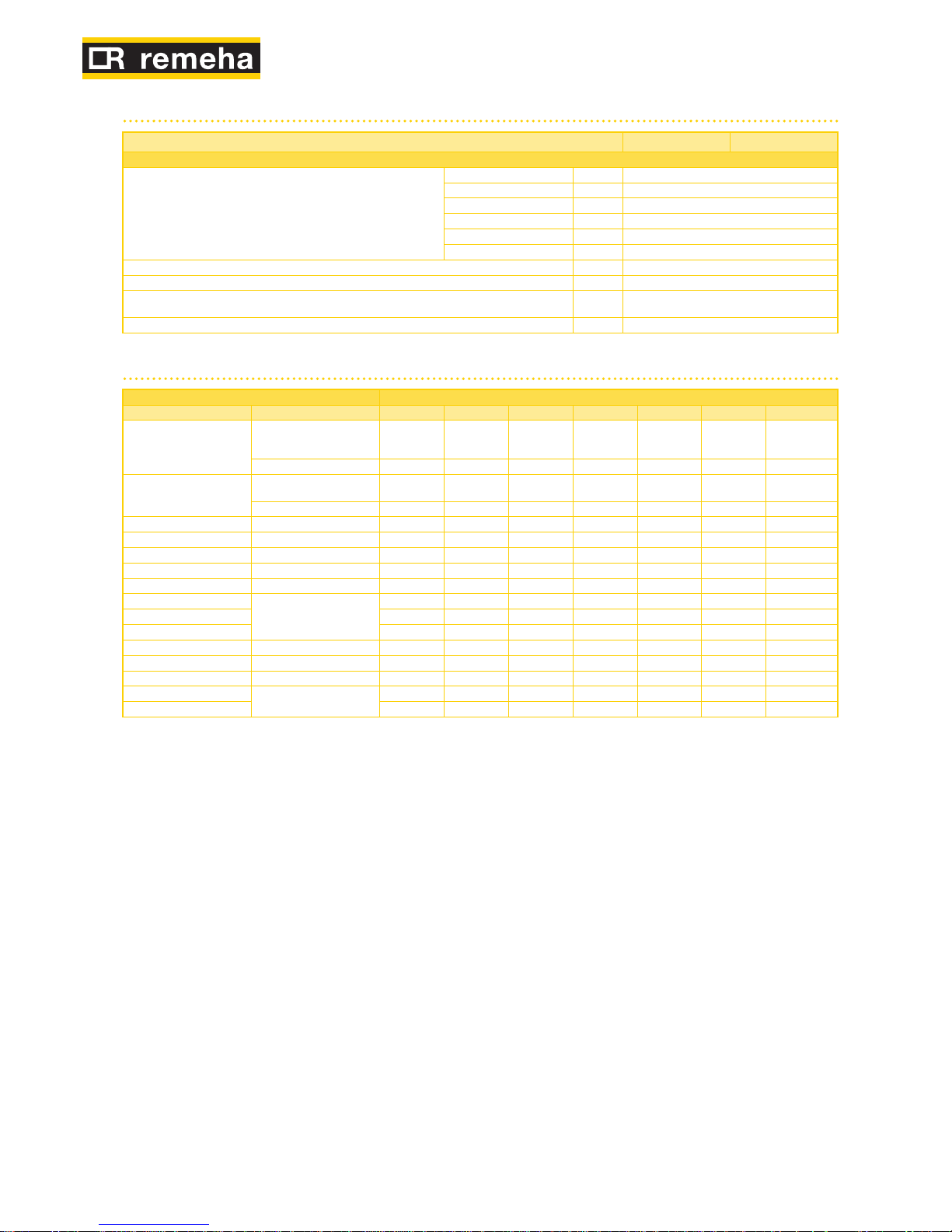
2.3 TECHNICAL DATA
Table 2.1 – GAHP-A LT technical data
GAHP-A LT S
OPERATION WHEN HEATING
OPERATING POINT A7W50
G.U.E. gas usage efficiency % 151 (1)
Thermal power kW 38,0 (1)
OPERATING POINT A7W35
G.U.E. gas usage efficiency % 165 (1)
Thermal power kW 41,7 (1)
Thermal capacity
Nominal (1013 mbar - 15°C) kW 25,7
true peak kW 25,2
NOx emission class 5
NOx emission ppm 25
CO emission ppm 36
Hot water delivery temperature
maximum for heating °C 55
maximum for DHW °C 70
Hot water return temperature
maximum heating °C 45
maximum for DHW °C 60
minimum temperature in
continuous operation**
°C 20
Hot water flow rate
nominal l/h 3000
maximum l/h 4000
minimum l/h 1400
Hot water pressure drop
nominal water pressure
(A7W50)
bar 0,43 (2)
Ambient air temperature (dry bulb)
maximum °C 40
minimum °C -20 (7)
Thermal differential nominal °C 10
gas consumption
methane G20 (nominal) m3/h 2,72 (3)
methane G20 (MIN) m3/h 1,34
G25 (nominal) m3/h 3,16 (9)
G25 (MIN) m3/h 1,57
G30 (nominal) kg/h 2,03 (4)
G30 (MIN) kg/h 0,99
G31 (nominal) kg/h 2,00 (4)
G31 (MIN) kg/h 0,98
ELECTRICAL SPECIFICATIONS
Power supply
Voltage V 230
TYPE SINGLE PHASE
Frequency
50 Hz
supply
50
Electrical power absorption
nominal kW 1,09 (5)
minimum kW -

10
GAHP-A LT S
Degree of protection IP X5D
INSTALLATION DATA
Level of acoustic pressure at 10 meters (maximum) dB(A) 45 (8)
Level of acoustic pressure at 10 meters (minimum) dB(A) Minimum storage temperature °C -30
Maximum operating pressure bar 4
Maximum condensation water flow rate l/h 4
Water content inside the apparatus l 4
Water fitting
TYPE F
thread " G 1 1/4
Gas fitting
TYPE F
thread " G 3/4
Fume outlet
Diameter (∅) mm 80
Residual head Pa 80
Size
width mm 848 (6)
height mm 1537 (6)
depth mm 1258
Weight In operation kg 400
GENERAL INFORMATION
INSTALLATION MODE B23P, B33, B53P
COOLING FLUID
AMMONIA R717 kg 7
WATER H2O kg 10
MAXIMUM PRESSURE OF THE COOLING CIRCUIT bar 35
** in transient operation, lower temperatures are allowed
Notes:
As per EN12309-2 evaluated over the actual thermal capacity.1.
-2.
PCI 34.02 MJ/m3 (1013 mbar – 15 ° C).3.
PCI 46.34 MJ/kg (1013 mbar – 15 ° C).4.
± 10% depending on power voltage and absorption tolerance of electric motors.5.
Overall dimensions excluding fumes pipes (see Figure 2.1 Dimensions (low noise 6.
version) → 13).
As an option, a version for operation down to -30 °C is available.7.
Free field, frontal, directionality factor 2.8.
PCI 29.25 MJ/m3 (1013 mbar – 15 ° C).9.
Table 2.2 – GAHP-A HT technical data
GAHP-A HT S
OPERATION WHEN HEATING
OPERATING POINT A7W50
G.U.E. gas usage efficiency % 152 (1)
Thermal power kW 38,3 (1)
OPERATING POINT A7W65
G.U.E. gas usage efficiency % 124 (1)
Thermal power kW 31,1 (1)
OPERATING POINT A-7W50
G.U.E. gas usage efficiency % 127 (1)
Thermal power kW 32,0 (1)
Thermal capacity
Nominal (1013 mbar - 15°C) kW 25,7
true peak kW 25,2
NOx emission class 5
NOx emission ppm 25
CO emission ppm 36
Hot water delivery temperature
maximum for heating °C 65
maximum for DHW °C 70
Hot water return temperature
maximum heating °C 55
maximum for DHW °C 60
minimum temperature in
continuous operation**
°C 30
Hot water flow rate
nominal l/h 3000
maximum l/h 4000
minimum l/h 1400
Hot water pressure drop
nominal water pressure
(A7W50)
bar 0,43 (2)

Installation, user and maintenance manual – GAHP-A
11
GAHP-A HT S
Ambient air temperature (dry bulb)
maximum °C 40
minimum °C -20 (7)
Thermal differential nominal °C 10
gas consumption
methane G20 (nominal) m3/h 2,72 (3)
methane G20 (MIN) m3/h 1,34
G25 (nominal) m3/h 3,16 (9)
G25 (MIN) m3/h 1,57
G30 (nominal) kg/h 2,03 (4)
G30 (MIN) kg/h 0,99
G31 (nominal) kg/h 2,00 (4)
G31 (MIN) kg/h 0,98
ELECTRICAL SPECIFICATIONS
Power supply
Voltage V 230
TYPE SINGLE PHASE
Frequency
50 Hz
supply
50
Electrical power absorption
nominal kW 1,09 (5)
minimum kW -
Degree of protection IP X5D
INSTALLATION DATA
Level of acoustic pressure at 10 meters (maximum) dB(A) 45 (8)
Level of acoustic pressure at 10 meters (minimum) dB(A) Minimum storage temperature °C -30
Maximum operating pressure bar 4
Maximum condensation water flow rate l/h 4
Water content inside the apparatus l 4
Water fitting
TYPE F
thread " G 1 1/4
Gas fitting
TYPE F
thread " G 3/4
Fume outlet
Diameter (∅) mm 80
Residual head Pa 80
Size
width mm 848 (6)
height mm 1537 (6)
depth mm 1258
Weight In operation kg 400
GENERAL INFORMATION
INSTALLATION MODE B23P, B33, B53P
COOLING FLUID
AMMONIA R717 kg 7
WATER H2O kg 10
MAXIMUM PRESSURE OF THE COOLING CIRCUIT bar 35
** in transient operation, lower temperatures are allowed
Notes:
As per EN12309-2 evaluated over the actual thermal capacity.1.
-2.
PCI 34.02 MJ/m3 (1013 mbar – 15 ° C).3.
PCI 46.34 MJ/kg (1013 mbar – 15 ° C).4.
± 10% depending on power voltage and absorption tolerance of electric motors.5.
Overall dimensions excluding fumes pipes (see Figure 2.1 Dimensions (low noise 6.
version) → 13).
As an option, a version for operation down to -30 °C is available.7.
Free field, frontal, directionality factor 2.8.
PCI 29.25 MJ/m3 (1013 mbar – 15 ° C).9.
12
Table 2.3 – PED data
GAHP-A HT S GAHP-A LT S
PED data
COMPONENTS UNDER PRESSURE
Generator l 18,6
Leveling chamber l 11,5
Evaporator l 3,7
Cooling volume transformer l 4,5
Cooling absorber solution l 6,3
Solution pump l 3,3
TEST PRESSURE (IN AIR) bar g 55
SAFETY VALVE PRESSURE CALIBRATION bar g 35
FILLING RATIO
kg of
NH3/l
0,146
FLUID GROUP GROUP 1°
Table 2.4 – Network gas pressure
E3-GS; E3-WS; E3-A; GAHP-GS; GAHP-WS; GAHP-A Gas supply pressure
Product categories Countries of destination G20 [mbar] G25 [mbar] G30 [mbar] G31 [mbar] G25.1 [mbar] G27 [mbar] G2,350 [mbar]
II
2H3B/P
AL, BG, CY, CZ, DK, EE, FI, GR,
HR, IT, LT, MK, NO, RO, SE,
SI, SK, TR
20 30 30
AT, CH 20 50 50
II
2H3P
AL, BG, CZ, ES, GB, HR, IE, IT,
LT, MK, PT, SI, SK, TR
20 37
RO 20 30
II
2ELL3B/P
DE 20 20 50 50
II
2Esi3P
FR 20 25 37
II
2HS3B/P
HU 25 30 30 25
II
2E3P
LU 20 50
II
2L3B/P
NL 25 50 50
II
2E3B/P
PL
20 37 37
II
2ELwLs3B/P
20 37 37 20 13
II
2ELwLs3P
20 37 20 13
I
2E(R)B ; I3P
BE 20 25 37
I
3P
IS 30
I
2H
LV 20
I
3B/P
MT
30 30
I
3B
30
Installation, user and maintenance manual – GAHP-A
13
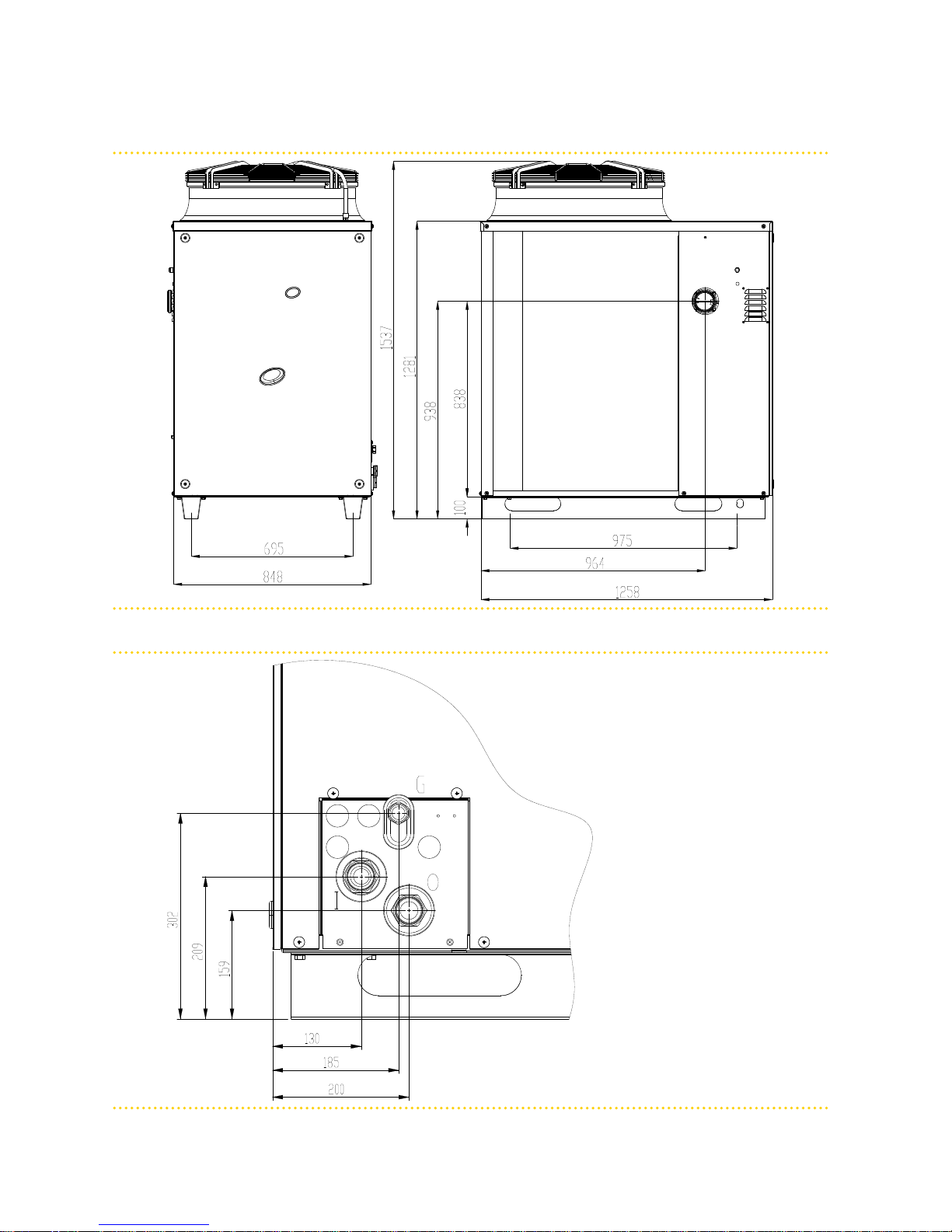
2.4 DIMENSIONS
Figure 2.1 – Dimensions (low noise version)
Front and side views (dimensions in mm).
Figure 2.2 – Service plate
Hydraulic/gas unions detail
LEGEND
G Gas fitting Ø ¾” F
I Inlet water fitting Ø 1¼” F
O Outlet water fitting Ø 1¼” F
14
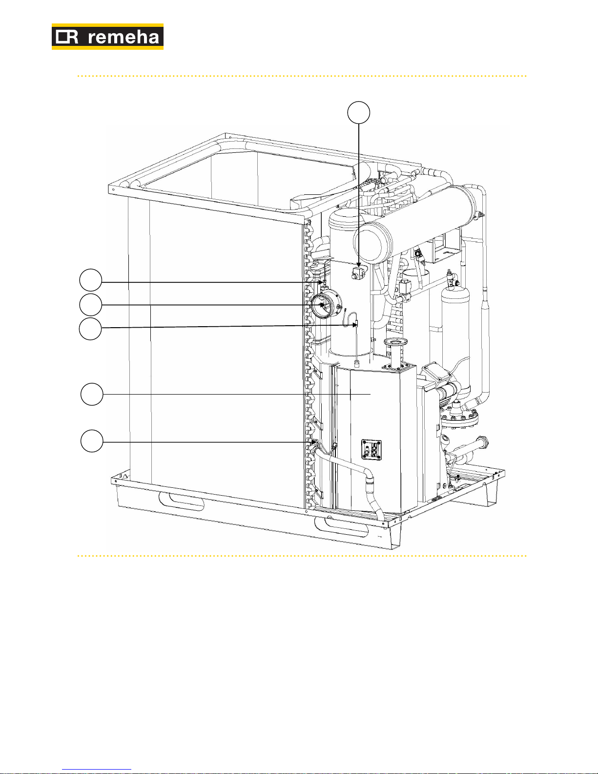
Figure 2.3 – Internal components - left side view
See table "Internal components"
Installation, user and maintenance manual – GAHP-A
15
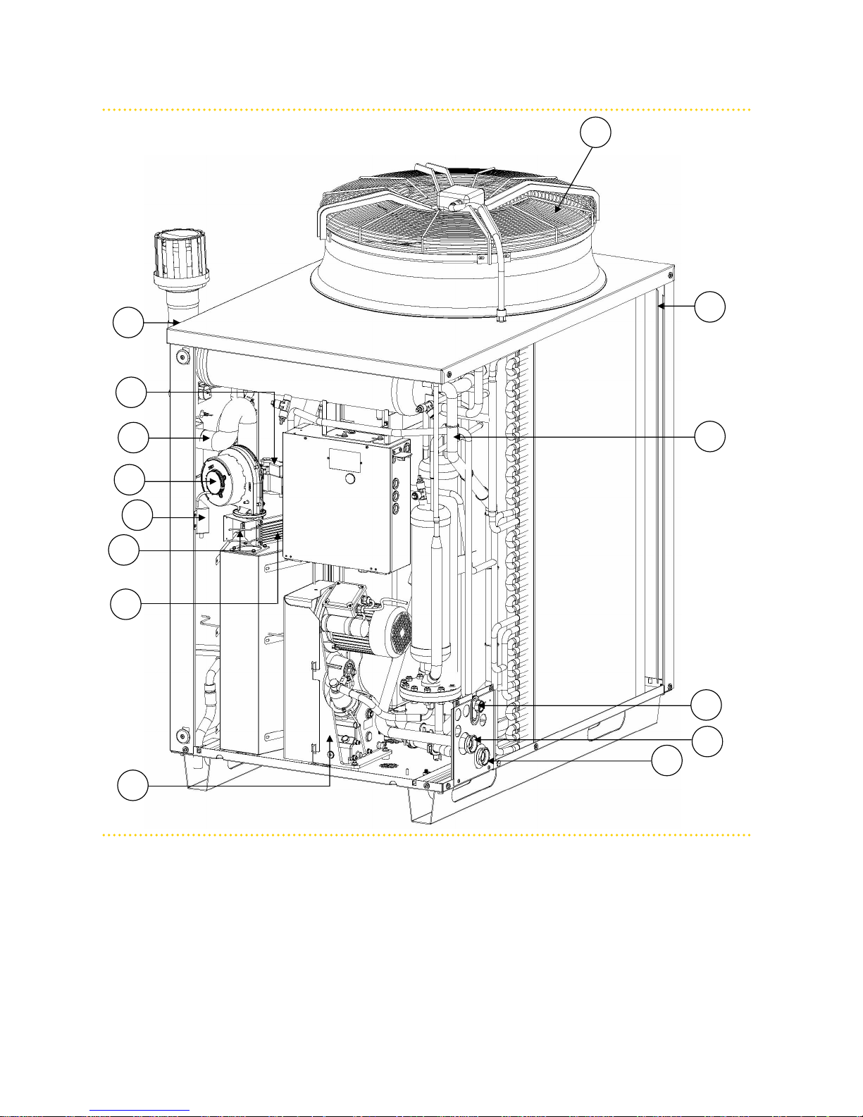
Figure 2.4 – Internal components - front view
See table "Internal components"
16
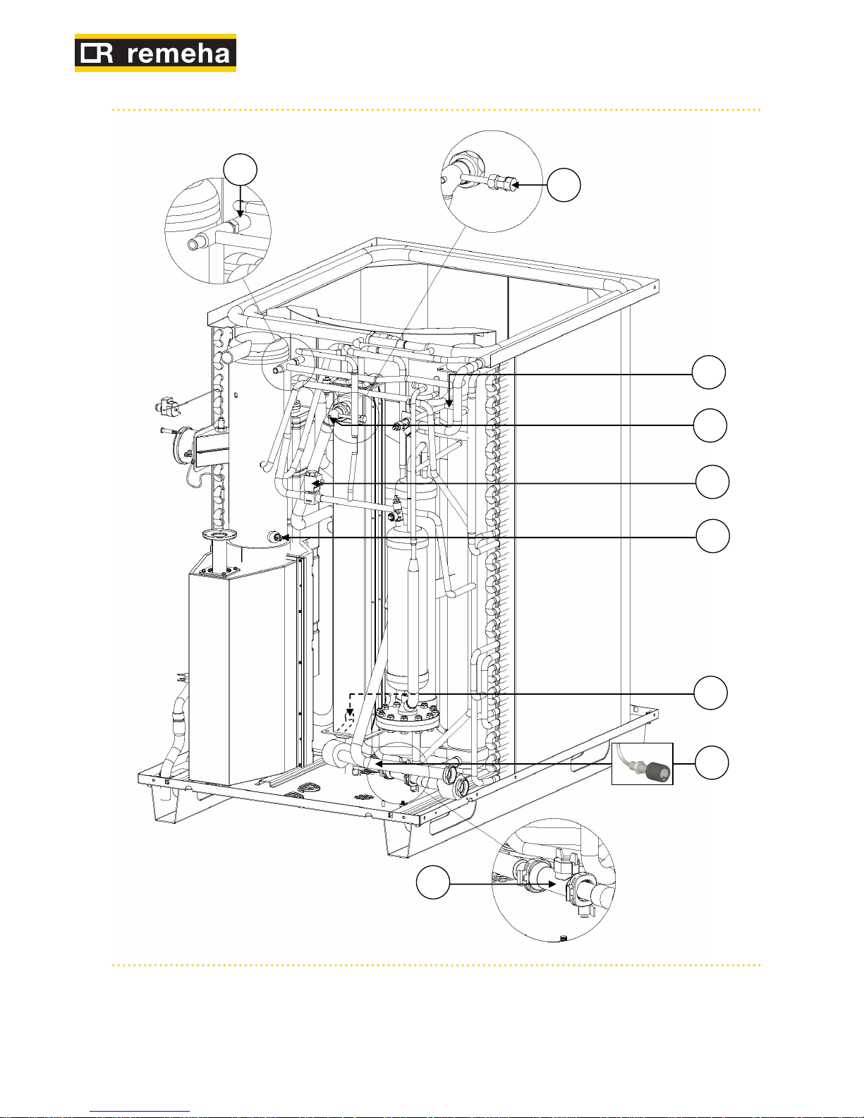
Figure 2.5 – Internal components - right side view
See table "Internal components"

Installation, user and maintenance manual – GAHP-A
17
Table 2.5 – Internal components
n. DESCRIPTION
1 Manual reset of the flue exhaust thermostat
2 Sensing element of the flue exhaust thermostat
3 DN80 flue exhaust connection
4 PT1000 flue exhaust temperature probe
5 Flame sensing / ignition electrodes
6 Condensate level sensor
8 Air fan
9 Tapping point for flue analisys
10 Gas valve
11 Combustion air hose
12 Combustion blower
13 Ignition transformer
14 Tmix air-gas mixture temperature probe
15 Blower-Gas valve heating element
16 Oil pump
17 1”¼ F water connection (flow)
18 1”¼ F water connection (return)
19 Gas fitting
20 TG generator temperature probe
21 TA outdoor temperature probe
22 Safety valve
23 HUBA flowmeter (flow pipe)
24 Not applicable
25 Flow temperature probe
26 Limit thermostat
27 Defrosting valve
28 Return temperature probe
29 Teva evaporator temperature probe
30 Air-vent manual valve
18
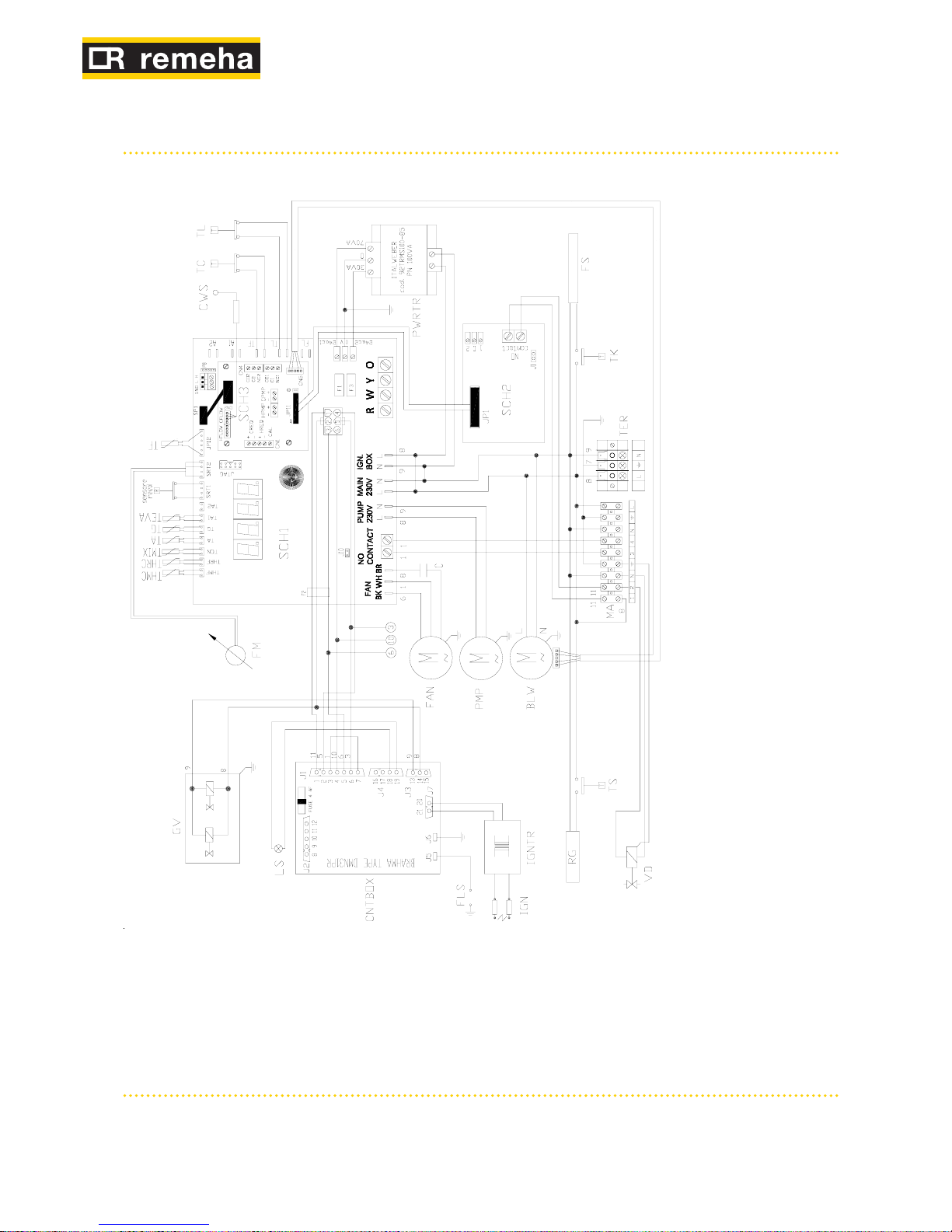
2.5 ELECTRICAL DIAGRAM OF THE APPLIANCE
Figure 2.6 – Wiring diagram of the unit with standard/ low noise fan (S)
LEGEND
SCH1 S61 circuit board
SCH2 W10 circuit board
SCH3 Mod10 circuit board
TER Appliance power terminal block
CNTBOX Flame controller
PWRTR Board transformer
BLW Blower
PMP Hydraulic pump
IGNTR Ignition transformer
IGN Ignition electrodes
FLS Flame sensor
LS Gas valve ON indicator lamp
GV Gas solenoid valve
TC Manual fumes thermostat
TL Generator limit thermostat
FM Flowmeter
CWS Condensation water sensor
VD Defrosting valve
FAN Fan
C Fan condenser
(not present on silenced units)
TS Gas valve heating element thermostat
FS Condensate hose heating element
RG Gas valve heating element
THRC Hot water return temperature sensor
THMC Hot water delivery temperature sensor
TMIX Combustion air temperature sensor
TA Ambient air temperature sensor
TG Generator temperature sensor
TF Fumes temperature sensor or generator fin sensor
TEVA Evaporator outlet temperature sensor
TK Condensate discharge heating element thermostat
MA Terminal block
REED Hydraulic pump rotation sensor
Installation, user and maintenance manual – GAHP-A
19
3 TRANSPORTATION AND POSITIONING
LIFTING AND PLACING THE APPLIANCE INTO POSITION
On receiving the appliance at the installation site, before placing into final position, check
there are no signs of transportation damages of the external panels or packaging.
Do not remove packaging during handling on the installation site.
Packing materials must be removed only after the appliance has been positioned on site.
After removing the packing materials, ensure that the appliance is intact and complete.
Packing items (plastic bags, polystyrene foam, nails, etc.) must be kept out of the reach of
children, as they are potentially dangerous.
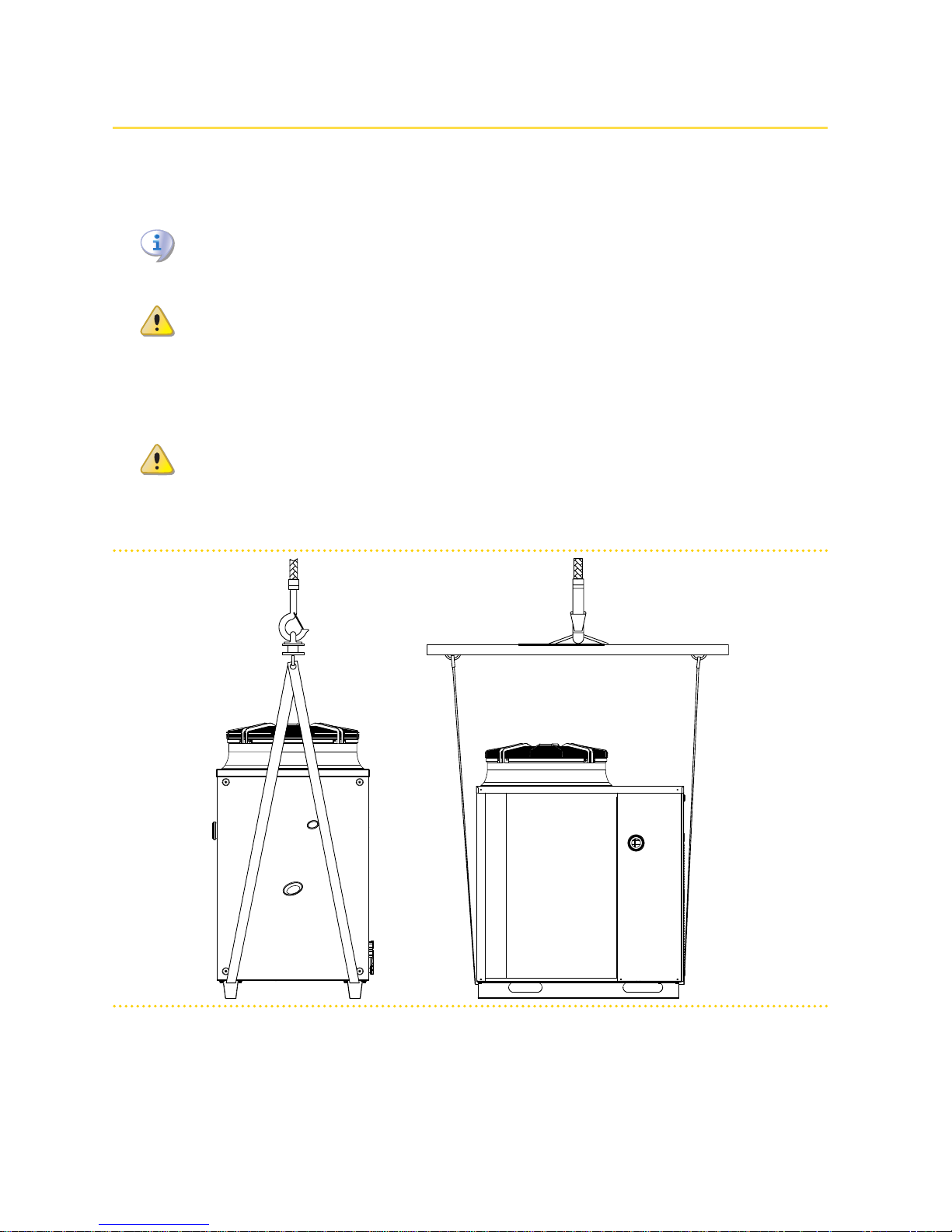
If the appliance has to be lifted, pass slings into the openings in the base supports and
use spreader bars to prevent the slings from damaging the casing during handling (see
Figure 3.1 Instruction for lifting → 19).
The crane and all lifting accessories must be properly sized for the load to be lifted.
The manufacturer cannot be held responsible for any damage that occurs during
the installation of the appliance.
Figure 3.1 – Instruction for lifting
The appliance must be installed outdoors, located in an area in which air circulates •
naturally and which does not require any particular protection from the weather.
In no case must the appliance be installed inside a room.
20
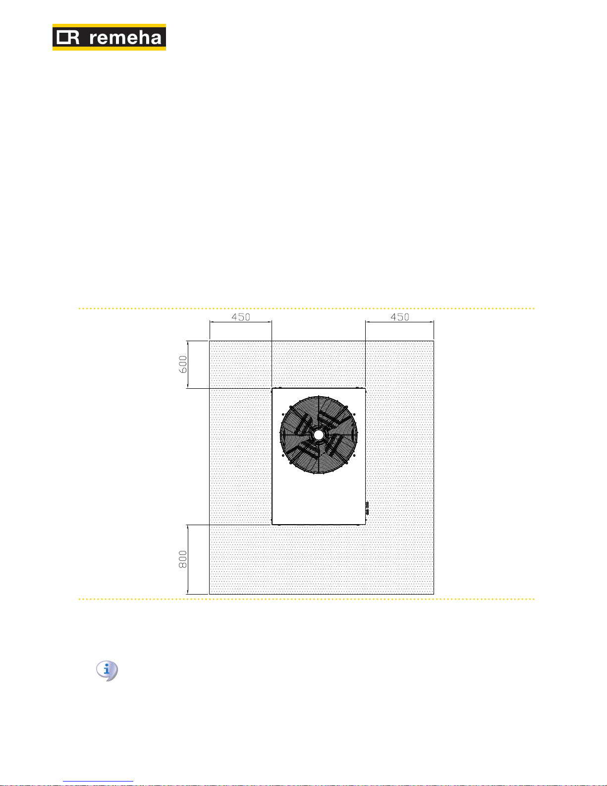
The front of the appliance must have a minimum clearance of 80 cm from walls •
or other fixed constructions; the right and left sides must have a minimum clearance of 45 cm; the minimum rear clearance from walls is 60 cm. (see Figure 3.2
Clearances → 20).
No obstruction or overhanging structure (roofs, eaves, balconies, ledges, trees) •
shall interfere either with the exhaust air flowing from the top of the appliance or
with the exhaust flue gas.
The appliance must be installed in such a way that the exhaust flue gas outlet is •
not in proximity of any external air inlet of a building. Respect current regulations
regarding the exhaust flue gas outlet.
Do not install the appliance close to the discharge of exhaust flue pipes, chimneys •
or the like, in order to avoid that warm or polluted air is fed through the evaporator.
To operate properly, the appliance needs clean air from the open environment.
If the appliance is installed near buildings, make sure it is not on the dripping line •
from gutters or similar.
The appliance can be installed at ground level, on a terrace or on a roof (if compatible
with its dimensions and weight).
Figure 3.2 – Clearances
CLEARANCES
Position the appliance so as to maintain minimum clearances from combustible surfaces, walls or other appliances, as illustrated in Figure 3.2 Clearances → 20.
Minimum clearances are required for maintenance accessibility.
When deciding on the installation position, especially if multiple units are used, consider
that each unit requires 11,000 m3/h of air for the coil. Make sure that the installation and
position allow for sufficient air flow to the coil and prevent recirculation, which would reduce efficiency and shut-down the appliance of the units and force them to switch off.

Installation, user and maintenance manual – GAHP-A
21
Place the appliance preferably far from environments where silence is required, such as
bedrooms, meeting rooms, etc.
Evaluate the noise impact of the appliance with respect to the installation site: avoid
placing the appliance in locations (such as corners of buildings) where noise could be
amplified (reverberation effect).
Avoid placing the appliance on the roof directly above locals requiring quietness.
Provide a retaining edge and proper evacuation of defrosting water to avoid possible
spilling and prevent icing on the ground of the defrosting water during winter time.
During winter operation, the appliance (depending on temperature and humidity conditions of the outdoor air) can carry out defrosting cycles melting the layer of frost/ice on
the coil.
The manufacturer may not be held responsible for any damage arising from failure
to observe this warning.
MOUNTING BASE
Always place the appliance on a levelled flat surface made of fireproof material and able
to support the weight of the appliance.
Installation at ground level
If a horizontal base is not available, create a concrete levelled socle larger than the base
of the appliance by at least 100-150 mm on each side.
Installation on a terrace or roof
Position the appliance on a levelled flat surface made of fireproof material.
The structure of the building must support the total weight of the appliance and the supporting base.
If necessary, provide a walkway around the appliance for accessibility.
Although the appliance produces vibrations of limited intensity, the use of antivibration
mounts (available as accessories, see Section ACCESSORIES → 66) is strongly recommended in such cases of installation on roofs or terraces in which resonance phenomena
may arise.
Moreover, it is advisable to use flexible connections (anti-vibration joints) between the
appliance and the hydraulic and gas supply pipes.
SUPPORTS AND LEVELLING
The appliance must be correctly levelled by placing a spirit level on the upper part.
If necessary, level the appliance with metal shimming; do not use wooden spacers as
these deteriorate quickly.

22
4 HYDRAULIC INSTALLATION
4.1 GENERAL INSTALLATION PRINCIPLES
Installation of the appliance may only be carried out by professionally qualified personnel
by i.e. firms qualified according to the current legislation of the country of installation.
"Professionally qualified personnel" means personnel with specific technical competence
in the sector of heating/cooling installations and gas appliances.
Installation of the appliance must be carried out in compliance with current local and
national regulations regarding the design, installation and maintenance of heating and
cooling installations and in accordance with the manufacturer's instructions.
In particular, current regulations regarding the following must be observed:
Gas equipment.•
Electrical equipment.•
Heating installations and heat pumps.•
Every other standard and regulation concerning the installation of equipment for •
summer and winter air conditioning using gas fuel.
Before realizing hydraulic system and gas supply for the appliance, the professionally
qualified personnel is advised to read Paragraph 2.1 Conformity to CE standards → 8, pro-
viding important recommendations about safety and references to current regulations.
Prior to installation, carry out careful internal cleaning of all pipes and every other component to be used both on the hydraulic system and on the fuel supply, in order to remove any debris that may compromise the operation of the appliance.
The manufacturer does not accept any contractual or extra-contractual liability for any
damage caused by errors in installation and/or failure to observe the abovementioned
regulations and the instructions supplied by the manufacturer itself.
The installer must provide the owner with a Declaration stating that the installation has
been completed in compliance with state-of-the-art practices, current national and local
regulations, and recommendations by the manufacturer.
Before contacting Technical Assistance for commissioning and first start-up, the installer
must ensure that:
the electricity and gas grids characteristics correspond to the specifications on the •
nameplate of the appliance;
the gas supply pressure is compliant with the value reported in Table 2.4 Network •
gas pressure → 12 (considering a tolerance of ±15%);
the appliance is fed by the type of gas for which it is designed;•
the gas supply system and water distribution system are sealed;•
the gas and electricity supply systems are properly rated for the capacity required •
by the appliance and are equipped with all safety and control devices required by
current regulations
Check that no safety and control devices are excluded, by-passed or not properly
working.
Installation, user and maintenance manual – GAHP-A
23
4.2 HYDRAULIC CONNECTIONS
General indications
The hydraulic installation may be realized using pipes in stainless steel, black steel, copper or crosslinked polyethylene for heating/cooling applications. All water pipes and
pipe connections must be properly insulated in compliance with current regulations to
prevent heat losses and outer condensation.
The components below are always to be fitted in proximity to the appliance:
FLEXIBLE JOINTS on water and gas connections of the appliance.•
PRESSURE GAGES on the inlet and outlet water pipes.•
FLOW REGULATION VALVE (shutter or balancing) at the water inlet pipe.•
WATER FILTER installed on the water inlet pipe.•
ISOLATION BALL VALVE on the water and gas pipes of the installation.•
3 BAR SAFETY VALVE installed on the outlet water pipe.•
EXPANSION TANK for the individual appliance, installed on the water outlet pipe •
(primary side). Provide a plant expansion tank in any case (secondary side), installed in the water outlet pipe.
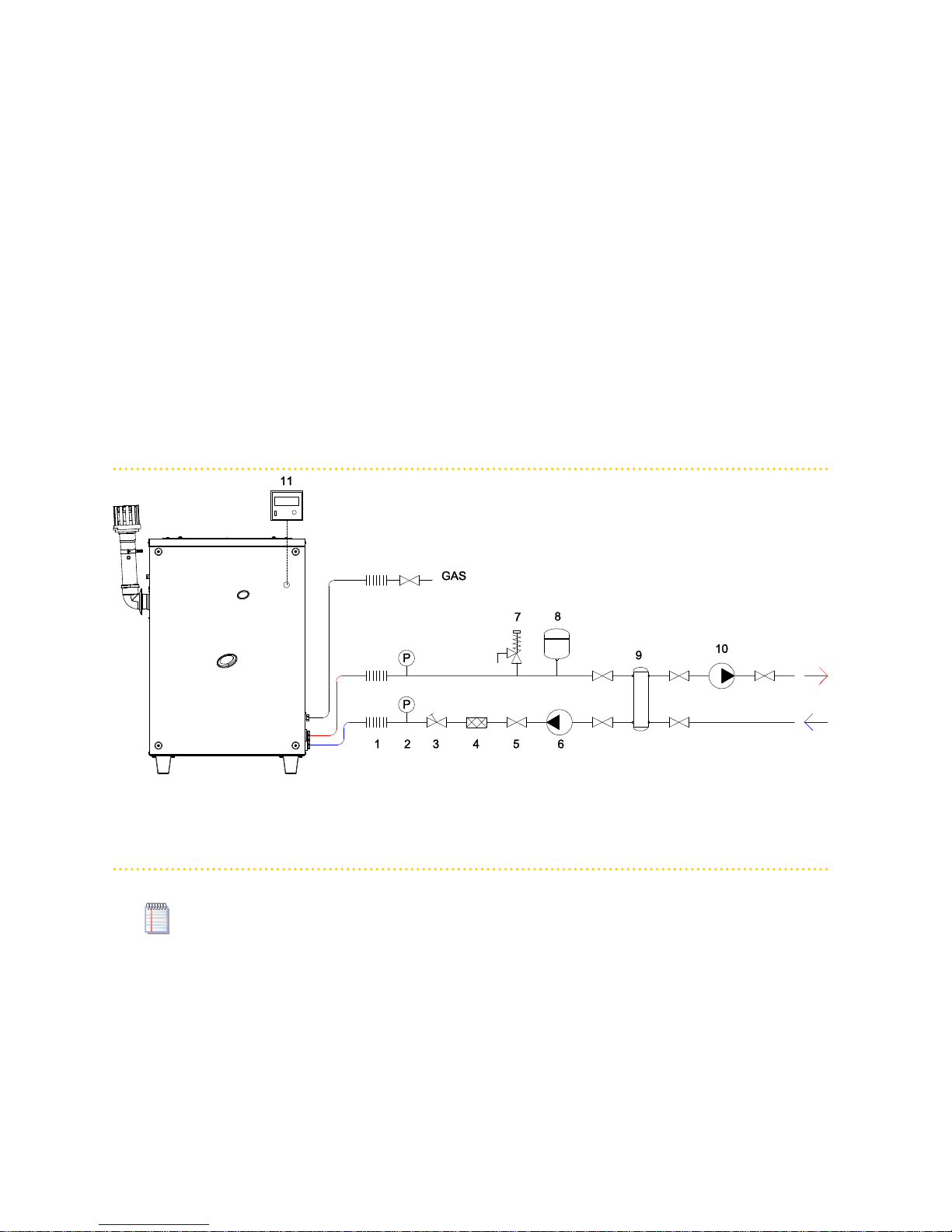
Figure 4.1 – Hydraulic plan
LEGEND
1 Fexible joint
2 Pressure gage
3 Flow regulator valve
4 Water filter
5 Isolation valve
6 Water pump (primary circuit)
7 Safety valve 3 bar
8 Expansion tank
9 Hydraulic separator / inertial tank with 4 connections
10 Water pump (secondary circuit)
11 Controller
The appliance is not equipped with an expansion tank; therefore it is necessary to install
a suitable expansion tank, sized for the maximum temperature range and maximum operating water pressure of the plant.
WATER CIRCULATION PUMP installed on the inlet pipe, flowing towards the •
appliance.
FILLING SYSTEM: if automatic filling systems are used, a seasonal check of the per-•
centage of monoethylene glycol in the plant is recommended.
4.3 GAS SUPPLY
The installation of gas supply pipes must be compliant with current regulations and
norms.
 Loading...