

Remcor CH750 Installation Manual
CHILLERS
MODELS: CH750, CH751 & CH951
Operator’s & Installation Manual
Release Date: April 19, 2002
Publication Number: 91256
Revision Date: May 5, 2010
Revision: D
Visit the IMI Cornelius web site at www.cornelius.com
for all your Literature needs.

CH SERIES CHILLER
OPERATOR’S & INSTALLATION MANUAL
The products, technical information and instructions contained in this manual are subject
to change without notice. These instructions are not intended to cover all details or variations of the equipment, nor to provide for every possible contingency in the installation,
operation or maintenance of this equipment. This manual assumes that the person(s)
working on the equipment have been trained and are skilled in working with electrical,
plumbing, pneumatic and mechanical equipment. It is assumed that appropriate safety
precautions are taken and that all local safety and construction requirements are being
met, in addition to the information contained in this manual.
To inquire about current revisions of this and other documentation or for assistance with
any Cornelius product contact:
www.cornelius.com
1-800-551-4423
This document contains proprietary information and it may not be
reproduced in any way without permission from Cornelius.
Printed in U.S.A.
Copyright © 2002-2010, All Rights Reserved, IMI Cornelius Inc.

Introduction . . . . . . . . . . . . . . . . . . . . . . . . . . . . . . . . . . . . . . . . . . . . . . . . . . . . . . . . . . . . . . . . . . . . . 1
Specifications. . . . . . . . . . . . . . . . . . . . . . . . . . . . . . . . . . . . . . . . . . . . . . . . . . . . . . . . . . . . . . . . . . . . 1
Installation Instructions . . . . . . . . . . . . . . . . . . . . . . . . . . . . . . . . . . . . . . . . . . . . . . . . . . . . . . . . . . . 1
Location . . . . . . . . . . . . . . . . . . . . . . . . . . . . . . . . . . . . . . . . . . . . . . . . . . . . . . . . . . . . . . . . . . . . . . 1
Plumbing . . . . . . . . . . . . . . . . . . . . . . . . . . . . . . . . . . . . . . . . . . . . . . . . . . . . . . . . . . . . . . . . . . . . . 1
Electrical . . . . . . . . . . . . . . . . . . . . . . . . . . . . . . . . . . . . . . . . . . . . . . . . . . . . . . . . . . . . . . . . . . . . . 1
Start-Up/Operation. . . . . . . . . . . . . . . . . . . . . . . . . . . . . . . . . . . . . . . . . . . . . . . . . . . . . . . . . . . . . . . . 2
Standard Thermostat Eliwell IC902 . . . . . . . . . . . . . . . . . . . . . . . . . . . . . . . . . . . . . . . . . . . . . . . . . 2
Maintenance . . . . . . . . . . . . . . . . . . . . . . . . . . . . . . . . . . . . . . . . . . . . . . . . . . . . . . . . . . . . . . . . . . . . . 3
Service . . . . . . . . . . . . . . . . . . . . . . . . . . . . . . . . . . . . . . . . . . . . . . . . . . . . . . . . . . . . . . . . . . . . . . . . . 3
Removing Wrapper . . . . . . . . . . . . . . . . . . . . . . . . . . . . . . . . . . . . . . . . . . . . . . . . . . . . . . . . . . . . . 3
Replacing Switch . . . . . . . . . . . . . . . . . . . . . . . . . . . . . . . . . . . . . . . . . . . . . . . . . . . . . . . . . . . . . . . 3
Replacing Fan Blade and/or Motor . . . . . . . . . . . . . . . . . . . . . . . . . . . . . . . . . . . . . . . . . . . . . . . . . 3
Replacing Pump. . . . . . . . . . . . . . . . . . . . . . . . . . . . . . . . . . . . . . . . . . . . . . . . . . . . . . . . . . . . . . . . 3
Fluid Recommendations . . . . . . . . . . . . . . . . . . . . . . . . . . . . . . . . . . . . . . . . . . . . . . . . . . . . . . . . . . . 4
Troubleshooting. . . . . . . . . . . . . . . . . . . . . . . . . . . . . . . . . . . . . . . . . . . . . . . . . . . . . . . . . . . . . . . . . . 5
Parts List. . . . . . . . . . . . . . . . . . . . . . . . . . . . . . . . . . . . . . . . . . . . . . . . . . . . . . . . . . . . . . . . . . . . . . . . 6
Warranty . . . . . . . . . . . . . . . . . . . . . . . . . . . . . . . . . . . . . . . . . . . . . . . . . . . . . . . . . . . . . . . . . . . . . . . . 8


CH Series Chiller Operator’s & Installation Manual
INTRODUCTION
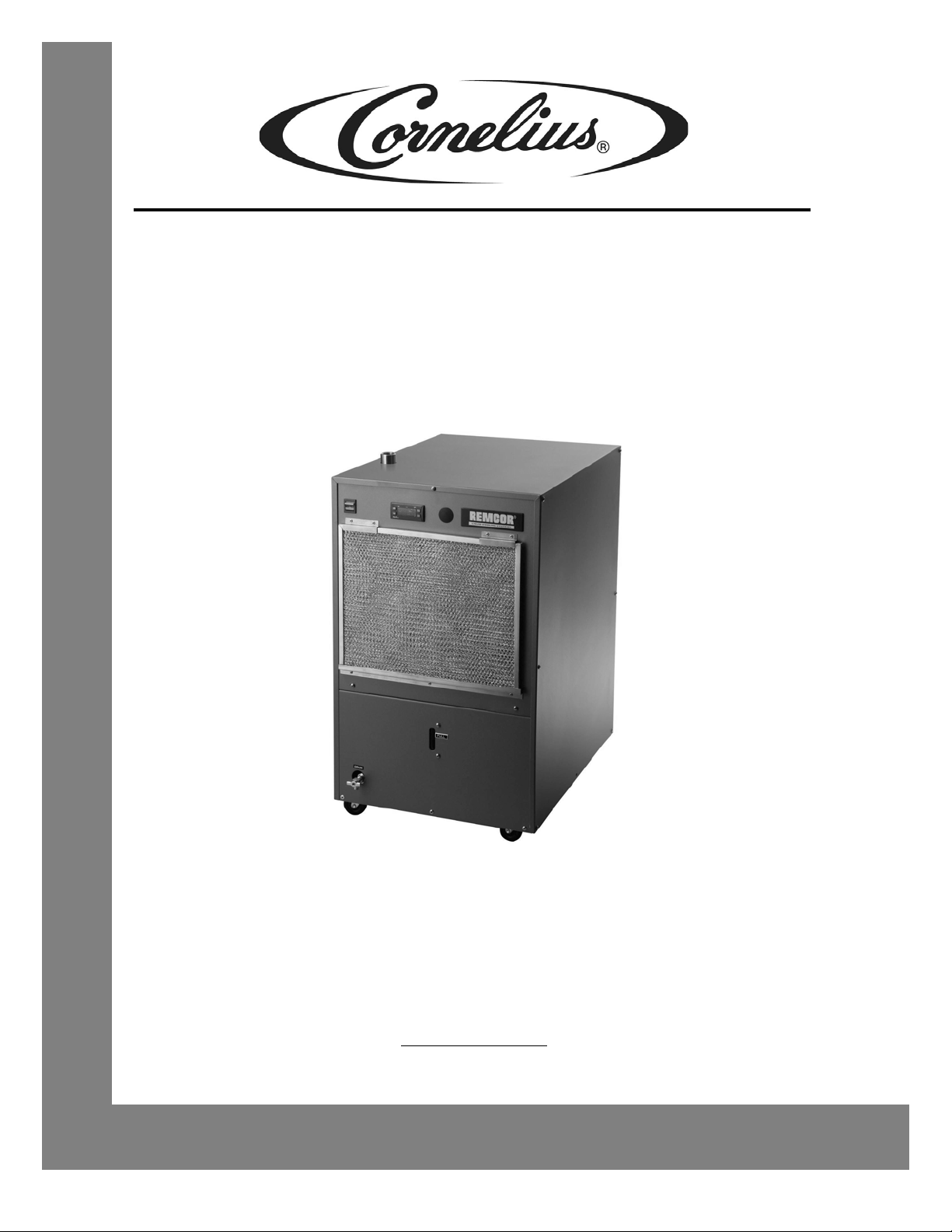
The Cornelius “CH” Series Water Chillers (Models CH750-A, CH751-A, and CH951-A) are specifically designed
to cool clean liquid before it is circulated to the cooling application. The Unit includes a complete refrigeration
system and associated controls housed in a sturdy sheet metal enclosure with perforated panels for air
circulation. Options include a reservoir and a choice of pumps and temperature controls to provide a self–
contained liquid cooling/circulation system tailored to a particular closed loop or tank cooling application.
On closed loop systems, the Unit is provided with a pump and reservoir for recirculation of water from the chiller
to the process. On tank cooling systems, the Unit is provided without the reservoir and the pump is optional for
recirculation of water from the chiller to the tank. Control temperature is sensed on the outlet of the chiller for
closed loop systems and it is sensed on the inlet of the chiller for tank cooling systems.
The pump options consist of a small magnetic drive pump as standard with a variety of magnetic drive and
positive displacement pumps available for particular flow and p ressure requireme nts . An optional byp ass valve is
available for the pump circulation system. (This valve is standard on Units utilizing the positive displacement
pumps). This can be used to adjust pump flow and pressure to match pr ocess requirements. This valve also
allows internal recirculation within the chiller in the event the chiller outlet is obstructed.
SPECIFICATIONS
CH750-A CH751-A CH951-A
Condensing Unit Horse Power 3/4 3/4 1
Electrical (Volts/Phase/Hz) 115/1/60 230/1/60 230/1/60
F. L. A. (Amps) 19 9.5 10
Reservoir Capacity (Gal) 5 5 5
Refrigerant 134-A Charge (Lbs) 3.5 3.5 4.0
Stainless Steel Connections 3/4-inch FPT 3/4-inch FPT 3/4-inch FPT
Operating Water Temp. Range
Net Weight (Lbs.) 250 250 250
Dimensions:Depth (inches)
Width (inches)
Height (inches)
40-100
o
F 40-100oF40-100
24-1/2
18-1/8
30-1/2
24-1/2
18-1/8
30-1/2
24-1/2
18-1/8
30-1/2
o
F
INSTALLATION INSTRUCTIONS
LOCATION
Locate the chiller indoors in a well ventilated area with ambient temperatures in the range of 65° F to 100° F.
Allow a minimum of six inches of clearance around the chiller for proper air circulation. Avoid hot air discharge
from other equipment or enclosed areas where heat could build up and cause a rise in ambient temperature.
PLUMBING
Follow standard plumbing practices and local codes in making water connections. Piping that is exposed to high
ambient temperatures may need to be insulated to prevent condensation and/or significant liquid heat gain.
ELECTRICAL
All wiring must conform to the National Electric Code and any applicable local codes. The chiller must be:
© 2002-2010, IMI Cornelius Inc. - 1 - Publication Number: 91256
 Loading...