

Page 1
IMI CORNELIUS INC g One Cornelius Place g Anoka, MN 55303-6234
Telephone (800) 238-3600 Facsimile (612) 422-3246
Installation/Service Manual
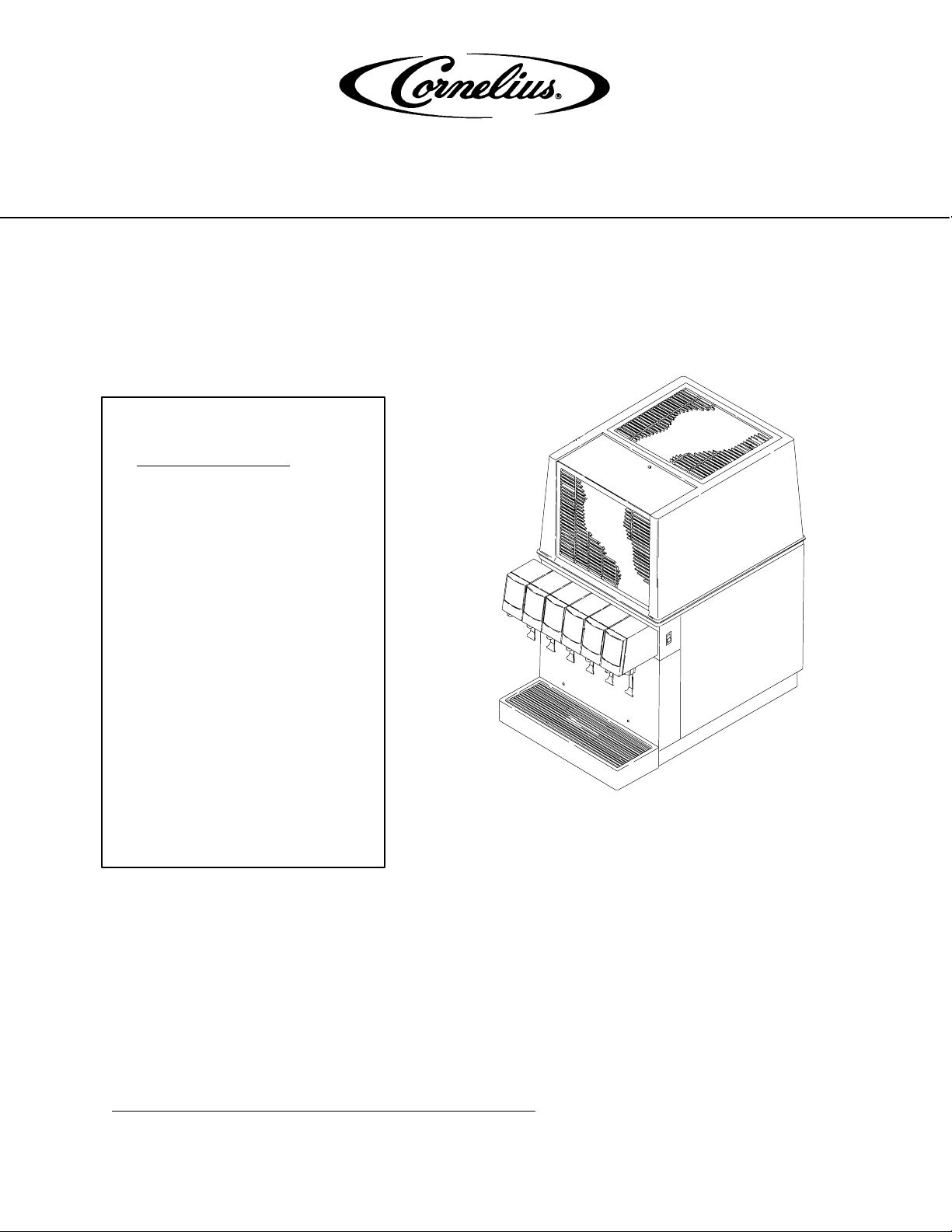
ADVENTURE POST-MIX DISPENSER
(R-134A REFRIGERANT)
IMPORTANT:
TO THE INSTALLER.
It is the responsibility of
the Installer to ensure that
the water supply to the
dispensing equipment is
provided with protection
against backflow by an air
gap as defined in
ANSI/ASME A112.1.2-1979;
or an approved vacuum
breaker or other such
method as proved effective
by test.
Water pipe connections
and fixtures directly
connected to a potable
water supply shall be
sized, installed, and
maintained according to
Federal, State, and Local
Codes.
Part No. 301137000
July 25, 1996
Revised: August 4, 1998
Control Code B–C–D
THIS DOCUMENT CONTAINS IMPORTANT INFORMATION
This Manual must be read and understood before installing or operating this equipment
IMI CORNELIUS INC; 1996–98
PRINTED IN U.S.A
Page 2

TABLE OF CONTENTS
SAFETY INFORMATION 1. . . . . . . . . . . . . . . . . . . . . . . . . . . . . . . . . . . . . . . . . . . . . . . . . . . .
RECOGNIZE SAFETY INFORMATION 1. . . . . . . . . . . . . . . . . . . . . . . . . . . . . . .
UNDERSTAND SIGNAL WORDS 1. . . . . . . . . . . . . . . . . . . . . . . . . . . . . . . . . . . .
FOLLOW SAFETY INSTRUCTIONS 1. . . . . . . . . . . . . . . . . . . . . . . . . . . . . . . . .
CO2 (CARBON DIOXIDE) WARNING 1. . . . . . . . . . . . . . . . . . . . . . . . . . . . . . . .
SHIPPING, STORING, OR RELOCATING UNIT 1. . . . . . . . . . . . . . . . . . . . . . .
GENERAL DESCRIPTION 3. . . . . . . . . . . . . . . . . . . . . . . . . . . . . . . . . . . . . . . . . . . . . . . . . .
UNIT DESCRIPTION 3. . . . . . . . . . . . . . . . . . . . . . . . . . . . . . . . . . . . . . . . . . . . . . . . . . .
WARRANTY REFERENCE INFORMATION 3. . . . . . . . . . . . . . . . . . . . . . . . . . . . . . .
THEORY OF OPERATION 4. . . . . . . . . . . . . . . . . . . . . . . . . . . . . . . . . . . . . . . . . . . . . .
INSTALLATION 7. . . . . . . . . . . . . . . . . . . . . . . . . . . . . . . . . . . . . . . . . . . . . . . . . . . . . . . . . . . .
UNPACKING AND INSPECTION 7. . . . . . . . . . . . . . . . . . . . . . . . . . . . . . . . . . . . . . . .
SELECTING OPERATING LOCATION 7. . . . . . . . . . . . . . . . . . . . . . . . . . . . . . . . . . .
INSTALLING UNIT 8. . . . . . . . . . . . . . . . . . . . . . . . . . . . . . . . . . . . . . . . . . . . . . . . . . . . .
INSTALLING UNIT ON COUNTERTOP 8. . . . . . . . . . . . . . . . . . . . . . . . . . . . . . .
FILL WATER TANK AND START REFRIGERATION SYSTEM 8. . . . . . . . . . .
CONNECTING DRIP TRAY DRAIN HOSE TO A PERMANENT DRAIN 9. . .
CONNECTING PLAIN WATER INLET SUPPLY LINE TO THE UNIT 9. . . . .
CONNECTING CARBONATED WATER SOURCE LINES TO THE UNIT 9. .
CONNECTING SYRUP SOURCE LINES TO THE UNIT 10. . . . . . . . . . . . . . . .
PREPARATION FOR OPERATION 10. . . . . . . . . . . . . . . . . . . . . . . . . . . . . . . . . . . . . . .
CO2 REGULATORS ADJUSTMENT 10. . . . . . . . . . . . . . . . . . . . . . . . . . . . . . . . .
UNIT OPERATION 10. . . . . . . . . . . . . . . . . . . . . . . . . . . . . . . . . . . . . . . . . . . . . . . . . . . . .
OPERATORS INSTRUCTIONS 12. . . . . . . . . . . . . . . . . . . . . . . . . . . . . . . . . . . . . . . . . . . . . .
Page
OPERATING CONTROLS 12. . . . . . . . . . . . . . . . . . . . . . . . . . . . . . . . . . . . . . . . . . . . . .
DISPENSING VALVE LEVER 12. . . . . . . . . . . . . . . . . . . . . . . . . . . . . . . . . . . . . . .
DISPENSING VALVES KEYED LOCK-OUT SWITCH 12. . . . . . . . . . . . . . . . . .
UNIT POWER SWITCH 12. . . . . . . . . . . . . . . . . . . . . . . . . . . . . . . . . . . . . . . . . . . .
DAILY PRE–OPERATION CHECK 12. . . . . . . . . . . . . . . . . . . . . . . . . . . . . . . . . . . . . . .
UNIT OPERATION 12. . . . . . . . . . . . . . . . . . . . . . . . . . . . . . . . . . . . . . . . . . . . . . . . . . . . .
ADJUSTMENTS 13. . . . . . . . . . . . . . . . . . . . . . . . . . . . . . . . . . . . . . . . . . . . . . . . . . . . . . .
ADJUSTING DISPENSING VALVES WATER FLOW RATE 13. . . . . . . . . . . . .
ADJUSTING WATER-TO-SYRUP “RATIO” (BRIX) OF DISPENSED
PRODUCT 13. . . . . . . . . . . . . . . . . . . . . . . . . . . . . . . . . . . . . . . . . . . . . . . . . . . . . . . .
CLEANING AND SANITIZING 13. . . . . . . . . . . . . . . . . . . . . . . . . . . . . . . . . . . . . . . . . . .
DAILY CLEANING OF UNIT 13. . . . . . . . . . . . . . . . . . . . . . . . . . . . . . . . . . . . . . . .
WEEKLY CLEANING OF DISPENSING VALVES 13. . . . . . . . . . . . . . . . . . . . . .
SANITIZING SYRUP SYSTEMS 13. . . . . . . . . . . . . . . . . . . . . . . . . . . . . . . . . . . . .
CHECKING DROP-IN REFRIGERATION ASSEMBLY CONDENSER COIL
FOR RESTRICTIONS 13. . . . . . . . . . . . . . . . . . . . . . . . . . . . . . . . . . . . . . . . . . . . . . . . . .
CHECKING ICE WATER BATH 13. . . . . . . . . . . . . . . . . . . . . . . . . . . . . . . . . . . . . . . . . .
CARBONATOR WATER PUMP YEARLY MAINTENANCE OR AFTER WATER
SYSTEM DISRUPTIONS 13. . . . . . . . . . . . . . . . . . . . . . . . . . . . . . . . . . . . . . . . . . . . . . .
i 301137000
Page 3

TABLE OF CONTENTS (cont’d)
SERVICE AND MAINTENANCE 15. . . . . . . . . . . . . . . . . . . . . . . . . . . . . . . . . . . . . . . . . . . . .
PREPARING UNIT FOR SHIPPING, STORING, OR RELOCATING 15. . . . . . . . . .
HOOD AND FRONT PANEL REMOVAL 15. . . . . . . . . . . . . . . . . . . . . . . . . . . . . . . . . .
HOOD REMOVAL 15. . . . . . . . . . . . . . . . . . . . . . . . . . . . . . . . . . . . . . . . . . . . . . . . .
FRONT ACCESS PANEL REMOVAL 15. . . . . . . . . . . . . . . . . . . . . . . . . . . . . . . . .
PERIODIC INSPECTION 15. . . . . . . . . . . . . . . . . . . . . . . . . . . . . . . . . . . . . . . . . . . . . . .
ADJUSTMENTS 15. . . . . . . . . . . . . . . . . . . . . . . . . . . . . . . . . . . . . . . . . . . . . . . . . . . . . . .
ADJUSTING CO2 REGULATORS 15. . . . . . . . . . . . . . . . . . . . . . . . . . . . . . . . . . .
ADJUSTING DISPENSING VALVES FOR WATER FLOW RATE 17. . . . . . . . .
ADJUSTING DISPENSING VALVES FOR WATER-TO-SYRUP “RATIO”
(BRIX) OF DISPENSED PRODUCT 17. . . . . . . . . . . . . . . . . . . . . . . . . . . . . . . . . .
CLEANING AND SANITIZING 17. . . . . . . . . . . . . . . . . . . . . . . . . . . . . . . . . . . . . . . . . . .
DAILY CLEANING OF UNIT 17. . . . . . . . . . . . . . . . . . . . . . . . . . . . . . . . . . . . . . . .
SANITIZING POST-MIX SYRUP SYSTEMS 17. . . . . . . . . . . . . . . . . . . . . . . . . .
CLEANING DROP-IN REFRIGERATION ASSEMBLY CONDENSER COIL 20. . . .
CHECKING ICE WATER BATH 20. . . . . . . . . . . . . . . . . . . . . . . . . . . . . . . . . . . . . . . . .
CLEANING WATER TANK 21. . . . . . . . . . . . . . . . . . . . . . . . . . . . . . . . . . . . . . . . . . . . . .
REMOTE CARBONATOR WATER PUMP YEARLY MAINTENANCE OR AFTER
WATER SYSTEM DISRUPTIONS 21. . . . . . . . . . . . . . . . . . . . . . . . . . . . . . . . . . . . . . . .
TROUBLESHOOTING 23. . . . . . . . . . . . . . . . . . . . . . . . . . . . . . . . . . . . . . . . . . . . . . . . . . . . . .
Page
TROUBLESHOOTING UNIT 23. . . . . . . . . . . . . . . . . . . . . . . . . . . . . . . . . . . . . . . . . . . .
WATER-TO-SYRUP ‘‘RATIO’’ TOO LOW OR TOO HIGH. 23. . . . . . . . . . . . . . .
ADJUSTMENT OF DISPENSING VALVE SYRUP FLOW REGULATOR DOES
NOT INCREASE TO DESIRED WATER-TO-SYRUP ‘‘RATIO’’.23. . . . . . . . . .
ADJUSTMENT OF DISPENSING VALVE SYRUP FLOW REGULATOR DOES
NOT DECREASE TO DESIRED WATER–TO–SYRUP ‘‘RATIO’’.24. . . . . . . . .
DISPENSED PRODUCT CARBONATION TOO LOW. 24. . . . . . . . . . . . . . . . . .
DISPENSED PRODUCT COMES OUT OF DISPENSING VALVE CLEAR BUT
FOAMS IN CUP OR GLASS. 24. . . . . . . . . . . . . . . . . . . . . . . . . . . . . . . . . . . . . . . .
DISPENSED PRODUCT PRODUCES FOAM AS IT LEAVES
DISPENSING VALVE. 24. . . . . . . . . . . . . . . . . . . . . . . . . . . . . . . . . . . . . . . . . . . . . .
NO PRODUCT DISPENSED FROM ALL DISPENSING VALVES. 25. . . . . . .
NO PRODUCT DISPENSED FROM ONE DISPENSING VALVE. 25. . . . . . . .
ONLY CARBONATED WATER DISPENSED. 25. . . . . . . . . . . . . . . . . . . . . . . . . .
ONLY SYRUP DISPENSED. 25. . . . . . . . . . . . . . . . . . . . . . . . . . . . . . . . . . . . . . . .
TROUBLESHOOTING REFRIGERATION SYSTEM 26. . . . . . . . . . . . . . . . . . . . . . . .
COMPRESSOR DOES NOT OPERATE. 26. . . . . . . . . . . . . . . . . . . . . . . . . . . . .
COMPRESSOR WILL NOT STOP AFTER SUFFICIENT ICE BANK IS
PRODUCED. 26. . . . . . . . . . . . . . . . . . . . . . . . . . . . . . . . . . . . . . . . . . . . . . . . . . . . .
COMPRESSOR OPERATES CONTINUOUSLY BUT DOES NOT FORM
SUFFICIENT ICE BANK. 26. . . . . . . . . . . . . . . . . . . . . . . . . . . . . . . . . . . . . . . . . . .
CONDENSER FAN MOTOR NOT OPERATING. 26. . . . . . . . . . . . . . . . . . . . . . .
AGITATOR MOTOR NOT OPERATING. 27. . . . . . . . . . . . . . . . . . . . . . . . . . . . . .
WARRANTY 28. . . . . . . . . . . . . . . . . . . . . . . . . . . . . . . . . . . . . . . . . . . . . . . . . . . . . . . . . . . . . .
301137000
ii
Page 4

TABLE OF CONTENTS (cont’d)
LIST OF FIGURES
FIGURE 1. ADVENTURE POST-MIX DISPENSER (SIX-FLAVOR UNIT
SHOWN) 3. . . . . . . . . . . . . . . . . . . . . . . . . . . . . . . . . . . . . . . . . . . . . . . . . . . . . . . . . . . . .
FIGURE 2. FLOW DIAGRAM (FIVE-FLAVOR UNIT SHOWN) 5. . . . . . . . . . . . . . .
FIGURE 3. FLOW DIAGRAM (SIX-FLAVOR UNIT SHOWN) 6. . . . . . . . . . . . . . . .
FIGURE 4. DISPENSER COMPONENTS (SIX-FLAVOR UNIT SHOWN) 16. . . . . .
FIGURE 5. WIRING DIAGRAM 22. . . . . . . . . . . . . . . . . . . . . . . . . . . . . . . . . . . . . . . . . .
LIST OF TABLES
TABLE 1. DESIGN DATA 4. . . . . . . . . . . . . . . . . . . . . . . . . . . . . . . . . . . . . . . . . . . . . . .
TABLE 2. LOOSE-SHIPPED PARTS 7. . . . . . . . . . . . . . . . . . . . . . . . . . . . . . . . . . . . .
Page
iii 301137000
Page 5
SAFETY INFORMATION
Recognize Safety Information
This is the safety-alert symbol. When you see this
symbol on our machine or in this manual, be alert to
the potentially of personal injury.
Follow recommended precautions and safe operating
practices.
Understand Signal Words
A signal word - DANGER, WARNING, OR CAUTION
is used with the safety-alert symbol. DANGER identi-
fies the most serious hazards.
DANGER
Safety signs with signal word DANGER or WARNING
are typically near specific hazards.
General precautions are listed on CAUTION safety
signs. CAUTION also calls attention to safety messages in this manual.
WARNING
CAUTION
Follow Safety Instructions
Carefully read all safety messages in this manual and on your machine safety signs. Keep safety signs in
good condition. Replace missing or damaged safety signs. Learn how to operate the machine and how to
use the controls properly. Do not let anyone operate the machine without instructions. Keep your machine in
proper working condition. Unauthorized modifications to the machine may impair function and/or safety and
affect the machine life.
CO2 (Carbon Dioxide) Warning
CO2 Displaces Oxygen. Strict Attention must be observed in the prevention of CO2 (carbon dioxide)
gas leaks in the entire CO2 and soft drink system. If a CO2 gas leak is suspected, particularly in a
small area, immediately ventilate the contaminated area before attempting to repair the leak. Personnel exposed to high concentration of CO2 gas will experience tremors which are followed rapidly by
loss of consciousness and suffocation.
Shipping, Storing, Or Relocating Unit
CAUTION: Before shipping, storing, or relocating this Unit, the syrup systems must be sanitized and
all sanitizing solution must be purged from the syrup systems. All water must also be purged from
the plain and carbonated water systems. A freezing ambient temperature will cause residual water
remaining inside the Unit to freeze resulting in damage to internal components of the Unit.
1 301137000
Page 6

THIS PAGE LEFT BLANK INTENTIONALLY
2301137000
Page 7
GENERAL DESCRIPTION
This manual is a guide for installing, operating, and maintaining this equipment. Refer to Table of Contents for
page location of detailed information pertaining to questions that may arise during installation, operation, service
and maintenance, or troubleshooting this equipment. This section gives the unit description, theory of operation,
and design data for the five and six-flavor Adventure Post-Mix Dispensers with electric dispensing valves,
hereafter referred to as ‘‘Units’’.
This Unit contains no User serviceable parts and must be installed and serviced by a qualified Service Person.
UNIT DESCRIPTION
The Units are compact with high-impact and corrosion resistant moulded lower housing. The Units may be
island-mounted or installed on a front or rear counter. The Unit refrigeration assemblies are the 1/3 H.P. drop-in
type and are easily removed for service and maintenance. Adjustable water flow controls and syrup flow
controls, located on the dispensing valves, are easily accessible to control water flow rate of dispensing valve
and Water-to-Syrup ‘‘Ratio’’ of dispensed product.
The only requirements for operation are installation of the Unit on a countertop, installation of LOOSE-SHIPPED
PARTS, filling Unit water tank with water, connection of Unit to a remote carbonator and syrup supplies,
adjustment of the CO2 regulators, plugging the Unit power cord into an electrical outlet, and adjusting
dispensing valves water and syrup flow controls for proper water flow rate and Water-to-Syrup ‘‘Ratio’’ of the
dispensed product.
NOTE: Optional 4-inch Legs (P/N 314744000) that will elevate the Unit 4-inches above the countertop
are available. When ordering legs, order a quantity of four.
WARRANTY REFERENCE INFORMATION
Warranty Registration Date
(to be filled out by customer)
Unit Part Number:
Serial Number:
Install Date:
Local Authorized
Service Center:
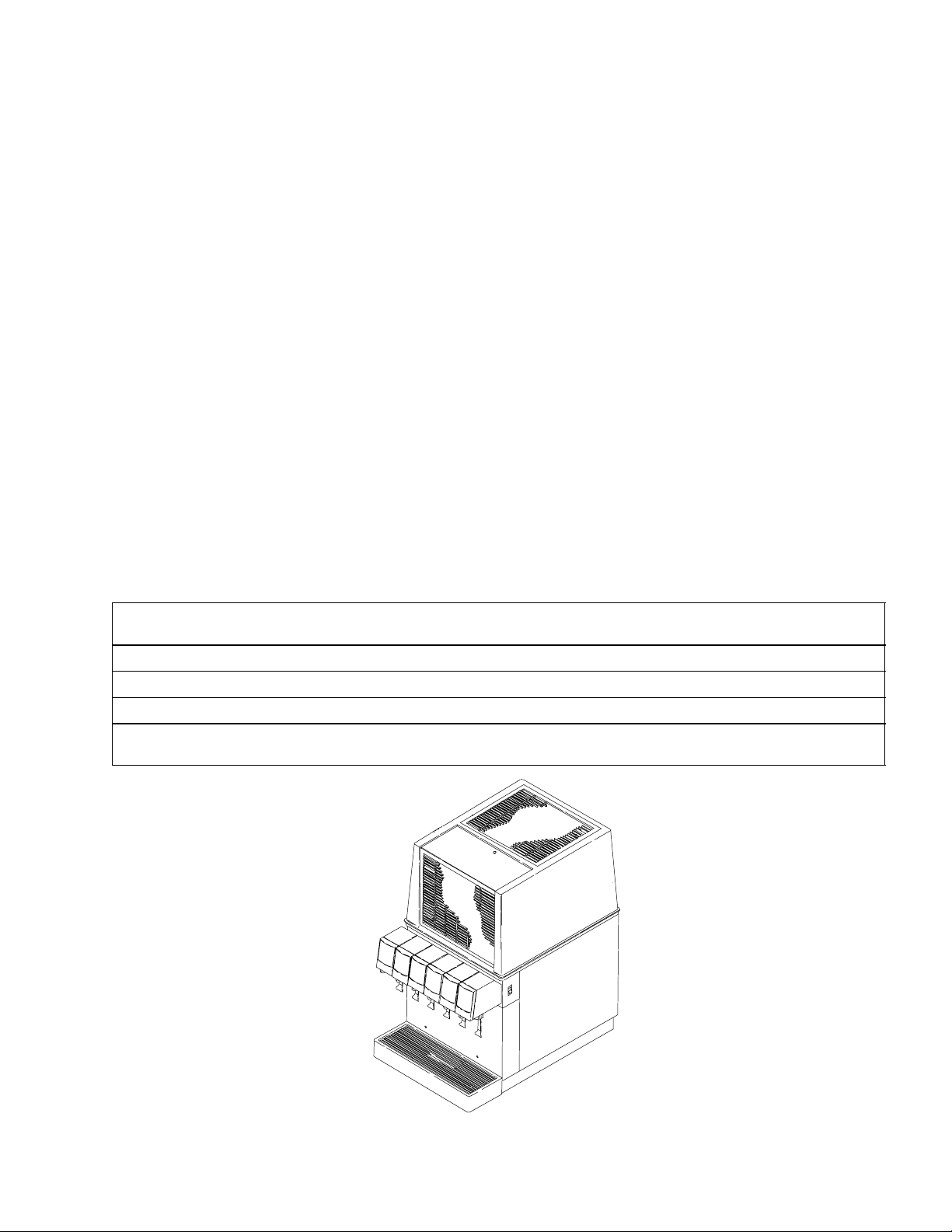
FIGURE 1. ADVENTURE POST-MIX DISPENSER (SIX-FLAVOR UNIT SHOWN)
3 301137000
Page 8
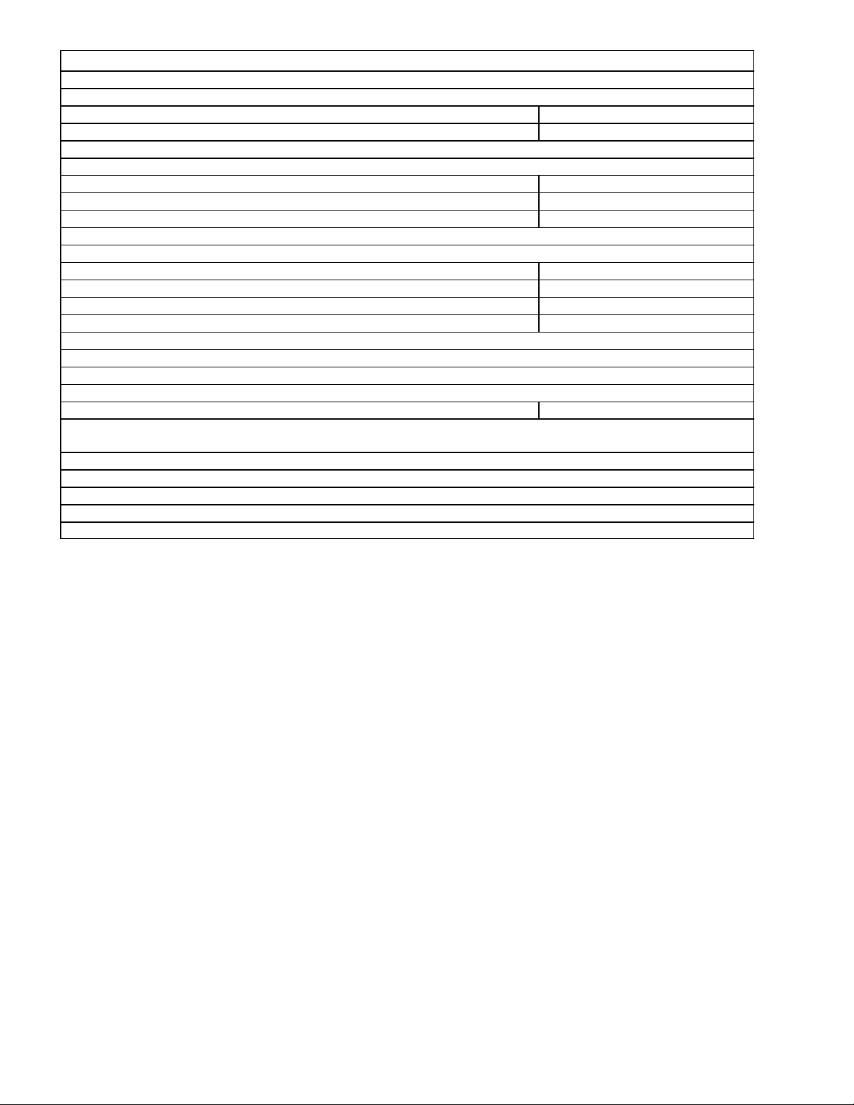
Table 1. Design Data
Unit Part Numbers:
Adventure Post-Mix Five-Flavor Unit 4173651200
Adventure Post-Mix Six-Flavor Unit 4173661200
Overall Dimensions:
Width 16-1/4 inches
Height 27-5/8 inches
Depth 24-1/2 inches
Weights:
Shipping 124 pounds
Dry Weight (approximate) 115 pounds
Ice Bank Weight (approximate) 31 pounds
Drop-in Refrigeration Ass’y 58 pounds
Water Bath Capacity (no ice bank) 9-3/4 gallons
Dispensing Rate:
12-oz. Drinks/Min. @ 40° F or Below (approximate) (see NOTE) 121
NOTE: Figure represents the number of 12-oz. drinks dispensed 40° F or below @ 75° F syrup and
water inlet temperature and 75° F ambient.
Refrigerant Requirement see Unit Nameplate
Electrical Requirements see Unit Nameplate
THEORY OF OPERATION
(see applicable Figure 2 or 3)
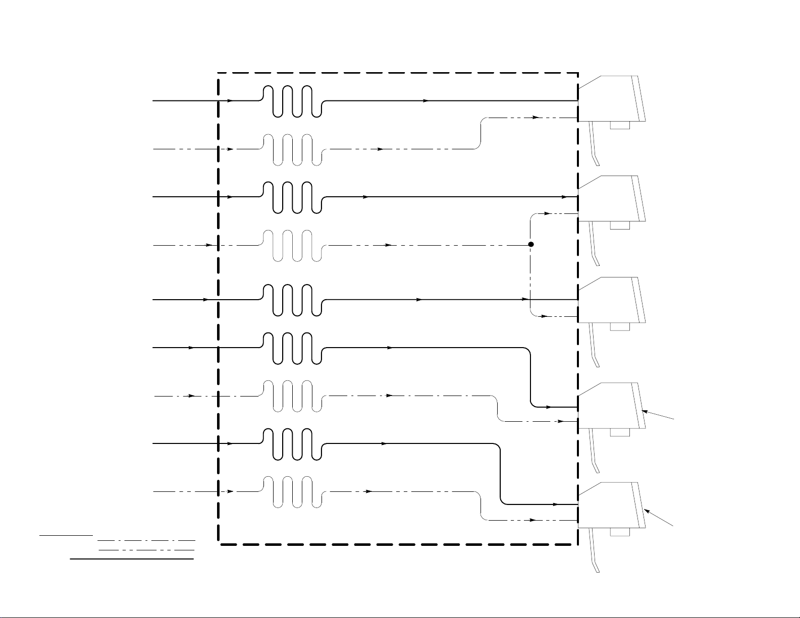
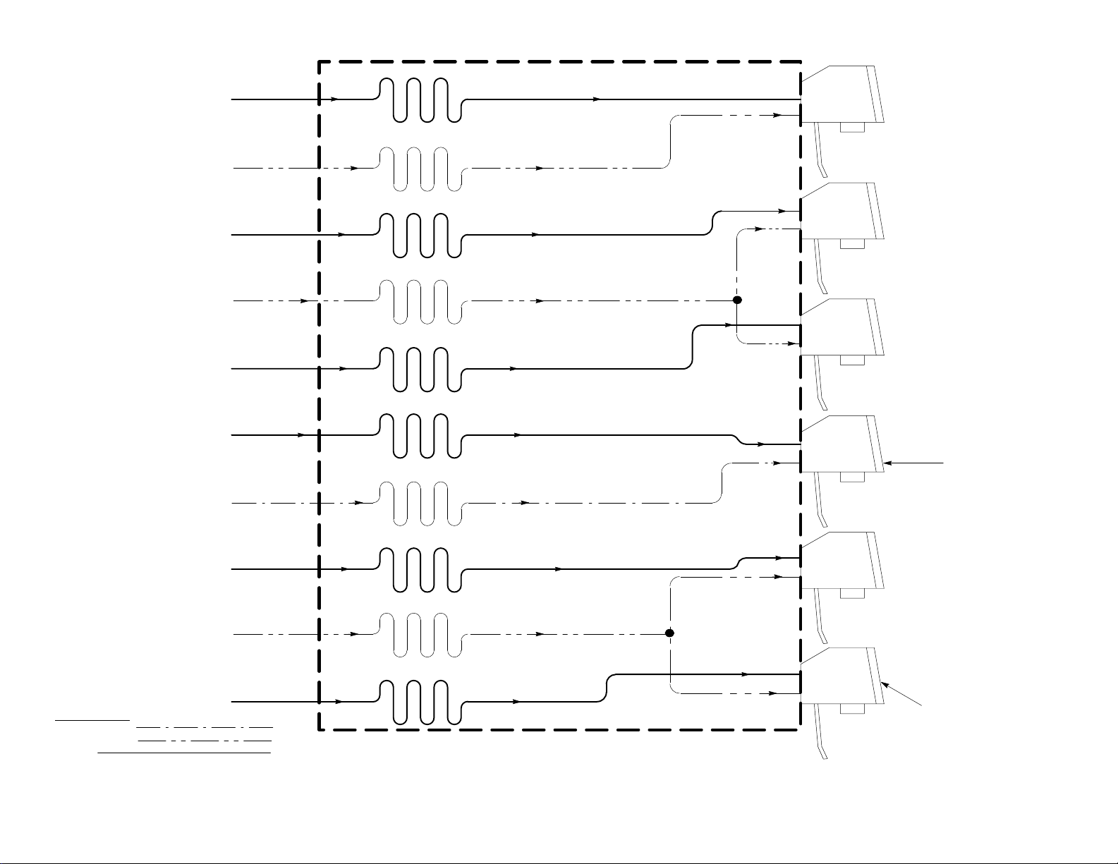
NOTE: The flow diagram (see applicable Figure 2 or 3) indicates plain water is to be connected to No. 4
dispensing valve enabling No. 4 valve to dispense a still (non-carbonated) drink and the remaining
dispensing valves dispensing carbonated drinks. If desired, carbonated water may also be connected
to the No. 4 dispensing valve enabling No. 4 valve to also dispense a carbonated drink.
A CO2 supply delivers carbon dioxide (CO2) gas through adjustable CO2 regulators to the syrup system and
also to the remote carbonator. Plain water enters remote carbonator carbonated water tank tank and is
carbonated by regulated CO2 gas pressure also entering the tank. When dispensing valves are opened, CO
pressure exerted upon the syrup supplies pushes syrup from the syrup supplies, through the Unit syrup cooling
coils, and on to the dispensing valves. Carbonated water is pushed from the remote carbonator carbonated
water tank by CO
gas head pressure and is pushed through the Unit carbonated water cooling coils to the
2
dispensing valves. Syrup and carbonated water meet and mix at the dispensing valves resulting in carbonated
drinks being dispensed. A still (non-carbonated) drink is dispensed from No. 4 dispensing valve in the same
manner as the carbonated drink except plain water is substituted for carbonated water resulting in a still
(non-carbonated) drink being dispensed.
2
The drop-in refrigeration assembly consists of a 1/3 horse power compressor, a condenser fan motor, and an
agitator motor. The compressor and condenser fan motor on and off operation are controlled by an ice bank
control.
4301137000
Page 9
SYRUP 1
CARB WATER
(NO.1)
1
SYRUP 2
CARB WATER
(NO. 2 AND 3)
SYRUP 3
2
3
5
SYRUP 4
PLAIN WATER
(NO. 4)
SYRUP 5
CARB WATER
(NO. 5)
4
STILL (NON-CAR-
BONATED) DRINK
5
301137000
LINE LEGEND
PLAIN WATER
CARB. WATER
SYRUP
DISPENSING
VALVE (5)
DISPENSER
FIGURE 2. FLOW DIAGRAM (FIVE-FLAVOR UNIT SHOWN)
Page 10
301137000
6
SYRUP 1
CARB WATER
(NO. 1)
SYRUP 2
CARB WATER
(NO. 2 AND 3)
SYRUP 3
DISPENSER
1
2
3
LINE LEGEND
PLAIN WATER
CARB. WATER
SYRUP
SYRUP 4
PLAIN WATER
(NO. 4)
SYRUP 5
CARB WATER
(NO. 5 AND 6)
SYRUP 6
4
STILL (NON-CAR-
BONATED) DRINK
5
6
DISPENSING
VALVE (6)
FIGURE 3. FLOW DIAGRAM (SIX-FLAVOR UNIT SHOWN)
Page 11
INSTALLATION
This section covers unpacking and inspection, selecting the operating location, installing the Unit, preparing the
Unit for operation, and Unit operation.
UNPACKING AND INSPECTION
(see Figure 4)
NOTE: The Unit was thoroughly inspected before leaving the factory and the carrier has accepted and
signed for it. Any damage or irregularities should be noted at the time of delivery (or not later than
15-days from date of delivery) and immediately reported to the delivering carrier. Request a written
inspection report from the Claims Inspector to substantiate any necessary claim. File the claim with the
delivering carrier, not with IMI Cornelius Inc.
1. After the Unit has been unpacked remove shipping tape and other packing material.
2. Remove one screw securing the Unit hood, then lift hood straight up and off the Unit.
3. Unpack LOOSE-SHIPPED PARTS. Make sure all items are present and in good condition.
Table 2. Loose-Shipped Parts
Item
No. Part No. Name 5-FL 6-FL
1 317659-040 Drip Tray 1 1
2 317660000 Cup Rest 1 1
3 317792000 Line Outlet Plug 1 1
4 318516000 Hose Clamp 1 1
5 0152 Customer Response Card 1 1
SELECTING OPERATING LOCATION
WARNING: To avoid possible fatal electrical shock or serious injury to the operator, it is
highly recommended that a GFCI (ground fault circuit interrupt) be installed in the
electrical circuit for the domestic Units. It is required that an ELCB (earth leakage circuit
breaker) be installed in the electrical circuit for the export Units
1. Position the Unit near a properly grounded electrical outlet with proper electrical requirements. The circuit
should be fused at 15-amps (slo-blow type fuse) or the circuit must be connected through an equivalent
HACR circuit breaker. The electrical outlet must be accessible for ease of connecting and disconnecting
the Unit power cord. No other electrical appliance should be connected to this circuit. ALL ELECTRICAL
WIRING MUST CONFORM TO NATIONAL AND LOCAL ELECTRICAL CODES.
2. Close to a plain water inlet supply line to be connected to the remote carbonator and also to be routed to
and be connected to the dispenser plain water inlet line that provides plain water to No. 3 dispensing valve.
3. Close to a permanent drain to route and connect Unit drip tray drain hose.
CAUTION: Do not place or store anything on top of the Unit.
4. Clearance above top of the Unit must be open to the ceiling. A minimum clearance of 6-inches must be
maintained on back side of the Unit and a minimum of 6-inches clearance to the nearest obstruction must
be maintained on both sides of the Unit. The front of the Unit must be open to the room. These clearances
must be provided to allow for proper air flow through the Unit to cool the refrigeration system.
7 301137000
Page 12
INSTALLING UNIT
CAUTION: This Unit is intended for indoor installation only. Do not install this Unit in an
outdoor environment which would expose it to the outside elements.
INSTALLING UNIT ON COUNTERTOP
(see Figure 4)
The Unit inlet supply lines, power cord, drip tray drain hose, and the water tank drain hose may either be routed
out the back of Unit base or through the hole cut in countertop under the Unit. Proceed to the applicable
installation procedure.
1. Out back of Unit base – Place Unit in operating location on the countertop. Route Unit inlet supply lines,
power cord, drip tray drain hose, and the water tank drain hose out through opening on back side of the
Unit base. Seal area around lines coming out of the Unit base with permagum or equivalent sealant
material.
Out hole cut in countertop under Unit – Place Unit in operating location on the countertop with its drip tray
edge flush with the countertop front edge. Mark Unit center line on edge of the countertop, then move the
Unit off to one side. Starting at the marked Unit center line on edge of the countertop, measure back
8-inches and mark center of the hole to be cut in the countertop. Cut 3-1/2 inch diameter hole in the
countertop. Place the Unit in position over the hole. Route Unit inlet supply lines, power cord, drip tray drain
hose, and the water tank drain hose down through hole cut in the countertop.
Close opening on back side of the Unit by Installing LINE OUTLET PLUG (item 3) in the opening.
NOTE: An alternate arrangement to avoid sealing the Unit base to the countertop as described, would
be to install the optional 4-inch Legs (P/N 314744000). When ordering legs, order a quantity of four.
2. To comply with National Sanitation Foundation (NSF) requirements, Unit base must be sealed to
countertop and all access holes to inside of Unit base must be sealed with permagum or other sealant
material. Proceed as follows to seal Unit base to countertop.
A. Tilt the Unit up to expose bottom of it’s base.
B. Liberally apply a silastic sealant such as Dow Corning RTV 731 or equivalent on the Unit base bottom
edges.
NOTE: Do not move the Unit after positioning or seal from the Unit base to countertop will be broken.
C. Lower Unit into operating position on the countertop to complete seal from Unit base to the
countertop.
D. Apply additional sealant around bottom of the Unit base. The seal must have a minimum radius of
1/2-inch to prevent crevices and to insure a complete seal.
E. Seal all access holes to inside of the Unit base with permagum or other sealant material.
FILL WATER TANK AND START REFRIGERATION SYSTEM
(see Figure 4)
1. Make sure plug in end of the water tank drain hose is in place.
NOTE: Use low–mineral–content water where a local water problem exists.
2. Remove water fill hole plug from top of the drop-in refrigeration assembly platform. Fill the water tank with
clean water to top of the stainless steel coils. USE LOW-MINERAL-CONTENT WATER WHERE A LOCAL
WATER PROBLEM EXISTS.
8301137000
Page 13
3. Install plug in the water fill hole.
4. Place power switch, located on right side of the Unit, in the ‘‘OFF’’ position.
WARNING: The Unit must be electrically grounded to avoid possible fatal electrical shock
or serious injury to the operator. The Unit power cord is equipped with a three-prong plug.
If a three-hole (grounded) electrical outlet is not available, use an approved method
to ground the Unit.
5. Plug the Unit power cord into a properly grounded electrical outlet.
6. Place the Unit power switch (located on right side of the Unit) in the ‘‘ON’’ position. The refrigeration
compressor, condenser fan motor, and agitator motor will start and begin forming an ice bank. When full ice
bank has been formed, the compressor and the condenser fan motor will stop but the agitator motor will
continue to operate circulating ice water bath in the water tank.
7. Install hood on the Unit and secure with screw.
CONNECTING DRIP TRAY DRAIN HOSE TO A PERMANENT DRAIN
(see Figure 4)
NOTE: The drip tray drain hose routed to a waste container is not recommended due to sanitation and
cleaning problems. Connection of the drain hose to a permanent drain is recommended.
Preferably, route lower end of the drip tray drain hose and connect it to a permanent drain.
CONNECTING PLAIN WATER INLET SUPPLY LINE TO THE UNIT
(see applicable Figure 2 or 3)
IMPORTANT: IMI Cornelius Inc; recommends that a water shutoff valve and a water filter be installed in
the plain water inlet supply line to be connected to the remote carbonator and also to the Unit plain
water inlet line.
NOTE: The flow diagram (see applicable Figure 2 or 3) indicates plain water is to be connected to No. 4
dispensing valve enabling No. 4 valve to dispense a still (non-carbonated) drink and the remaining
dispensing valves dispensing carbonated drinks. If desired, carbonated water may also be connected
to the No. 4 dispensing valve enabling No. 4 valve to also dispense a carbonated drink.
1. Remove two screws securing front access panel, then remove panel for access to water and syrup inlet
lines on front of the Unit.
2. Route plain water source line from plain water source up to and to a point behind the Unit front access
panel.
3. Connect plain water source line to the Unit plain water inlet line labeled ‘‘WATER’’. This plain water inlet line
provides water to the dispenser No. 4 dispensing valve that dispenses a still (non-carbonated) drink.
CONNECTING CARBONATED WATER SOURCE LINES TO THE UNIT
(see applicable Figure 2 or 3)
1. Route the carbonated water source lines from the remote carbonator up to and to a point behind the Unit
front access panel.
2. Connect the carbonated water source lines to Unit carbonated water inlet lines labeled ‘‘CO2 WATER’’.
9 301137000
Page 14
CONNECTING SYRUP SOURCE LINES TO THE UNIT
(see applicable Figure 2 or 3)
NOTE: Unit syrup inlet lines are labeled to identify dispensing valves they serve. For example: Line
labeled No. 1 must be connected to syrup source line that provides syrup to be dispensed from No. 1
dispensing valve (No. 1 dispensing valve is valve on right side when facing front of Unit).
1. Route syrup source lines (numbered for identification) from the syrup source location up to and to a point
behind the Unit front access panel.
2. Connect the numbered syrup source lines to the corresponding labeled Unit syrup inlet lines. DO NOT
ACTIVATE SYRUP SYSTEMS AT THIS TIME.
PREPARATION FOR OPERATION
CO2 REGULATORS ADJUSTMENT
WARNING: CO2 displaces oxygen. Strict attention must be observed in the prevention of
CO2 (carbon dioxide) gas leaks in the entire CO2 and soft drink system. If a CO2 gas leak is
suspected, particularly in a small area, immediately ventilate the contaminated area before
attempting to repair the leak. Personnel exposed to high concentration of CO2 gas will experience
tremors which are followed rapidly by loss of consciousness and suffocation.
1. Turn on CO
2. Check entire CO2 system for leaks and repair leaks if evident.
3. Adjusting Carbonator CO2 Regulator.
Refer to manual provided with the carbonator and adjust the carbonator CO2 regulator for operating
pressure.
4. Adjusting Syrup Supplies CO2 Regulator.
SUGAR SYRUP TANKS SYSTEM CO2 REGULATOR
Adjust syrup tanks CO2 regulator to a minimum of 45-psi.
SYRUP PUMPS (BAG-IN-BOX SYSTEM)
Adjust the syrup pumps CO2 regulator to 70-psi. DO NOT EXCEED MAXIMUM CO2 PRESSURE
SPECIFIED ON THE SYRUP PUMPS.
supply to the system CO
2
regulators.
2
UNIT OPERATION
1. Open plain water inlet supply line shutoff valve.
2. Plug remote carbonator power cord into electrical outlet. The carbonator will start and continue to operate
until the carbonated water tank is full of carbonated water.
3. Place dispensing valves keyed lock-out switch on left side of the Unit in ‘‘ON’’ (vertical) position to operate
the dispensing valves.
4. Dispense from all dispensing valves until all air is purged from carbonated and plain water systems and
until plain and carbonated water are dispensed. Check for carbonated and plain water leaks and repair if
evident.
IMPORTANT: All syrup systems must be sanitized before the Unit is put into operation.
10301137000
Page 15

5. Sanitize the syrup systems as instructed in the SERVICE AND MAINTENANCE section of this manual.
6. Activate syrup supplies to the Unit.
7. Dispense from all dispensing valves to purge all air from the syrup systems.
NOTE: The dispensing valves adjustable water flow controls are factory adjusted and should require
no further adjustment. If water flow rate readjustment should become necessary, consult the
dispensing valve manufacturer for the proper adjustment procedure. The water flow rate readjustment
must be performed prior to adjusting the dispensing valves for Water-To-Syrup “Ratio” (Brix) of the
dispensed product.
8. Adjusting Dispensing Valves For Water-To-Syrup “Ratio” (Brix) Of Dispensed Product.
The dispensing valves are each equipped with adjustable syrup flow controls. The Water-To-Syrup “Ratio”
(Brix) of the dispensed product is controlled by adjustment of these syrup flow controls. Consult the
dispensing valves manufacturer for the adjustment procedure.
9. Recheck the entire installation for CO2, plain water, and syrup leaks and repair if evident.
10. Install hood on Unit and secure with screw.
11. Install front access on the Unit and secure with two screws
11 301137000
Page 16
OPERATORS INSTRUCTIONS
This section covers operating controls, daily pre-operation check, Unit operation, and service and maintenance
procedures.
WARNING: Disconnect electrical power to the Unit to prevent personal injury before
attempting any internal maintenance. Only qualified personnel should service the internal
components or electrical wiring.
CAUTION: Do not place or store anything on top of the Unit.
OPERATING CONTROLS
(see Figure 4)
DISPENSING VALVE LEVER
The dispensing valve lever, located below the dispensing valve, need only to be pressed with cup or glass to
dispense product.
DISPENSING VALVES KEYED LOCK-OUT SWITCH
The dispensing valves keyed lock-out switch, located on left side of the Unit, must be in the ‘‘ON’’ (vertical)
position to operate the electric dispensing valves. The keyed lock-out switch placed in the ‘‘OFF’’ (horizontal)
position, turns off electrical power to the dispensing valves.
UNIT POWER SWITCH
The Unit power switch, located on right side of the Unit, must be in the ‘‘ON’’ position before the Unit will
operate.
DAILY PRE–OPERATION CHECK
1. The CO2 supply should be checked daily to make sure there is an adequate supply. If necessary, replenish
the CO2 supply.
2. Make sure there is a sufficient syrup supply. If necessary, replenish the syrup supply.
3. Make sure the drip tray is clean and a clean cup rest is in place in the drip tray.
UNIT OPERATION
1. Make sure Unit power switch, located on right side of the Unit, is in the “ON” position.
2. Make sure dispensing valves keyed lock-out switch, located on left side of the Unit, is in the ‘‘ON’’ (vertical)
position.
3. Press cup or glass against the dispensing valve lever and dispense until cup or glass is full of product, then
release the lever.
12301137000
Page 17

ADJUSTMENTS
ADJUSTING DISPENSING VALVES WATER FLOW RATE
If necessary to adjust the dispensing valves for water flow rate, adjust as instructed in SERVICE AND
MAINTENANCE section of this manual..
ADJUSTING WATER-TO-SYRUP “RATIO” (BRIX) OF DISPENSED PRODUCT
If necessary to adjust the dispensing valves for Water-To-Syrup “Ratio” (Brix) of the dispensed product, adjust
as instructed in SERVICE AND MAINTENANCE section of this manual.
CLEANING AND SANITIZING
DAILY CLEANING OF UNIT
Daily cleaning procedure for the Unit should be performed at end of daily operation as instructed in the
SERVICE AND MAINTENANCE section of this manual..
WEEKLY CLEANING OF DISPENSING VALVES
The dispensing valves should be cleaned at least once a week by a qualified Service Person.
SANITIZING SYRUP SYSTEMS
The syrup systems should be sanitized every 90-days as instructed in SERVICE AND MAINTENANCE section
of this manual. The sanitizing procedures should be performed by a qualified Service Person.
CHECKING DROP-IN REFRIGERATION ASSEMBLY CONDENSER COIL
FOR RESTRICTIONS
NOTE: Circulating air, required to cool the refrigeration assembly condenser coil, is drawn in through
grille on front and is exhausted through grille on top of the hood. Restricting air in and out of the Unit
will decrease the refrigeration system cooling efficiency.
Area on top of the hood must be kept free of obstructions at all times. Make sure nothing is stored on top of the
hood. The condenser coil must be cleaned every 30-days as instructed in SERVICE AND MAINTENANCE
section of this manual to maintain proper cooling of the condenser coil. The condenser coil cleaning procedure
should be performed by a qualified Service Person.
CHECKING ICE WATER BATH
A ‘‘gurgle’’ heard from the Unit indicates water level in water tank is low and more water should be added for
maximum product cooling. Water should be added to the water tank as instructed in SERVICE AND
MAINTENANCE section of this manual. This procedure should be performed by a qualified Service Person.
CARBONATOR WATER PUMP YEARLY MAINTENANCE OR AFTER WATER
SYSTEM DISRUPTIONS
The remote carbonator water pump water inlet strainer screen and the liquid double check valve must be
inspected and cleaned by a qualified Service Person at least once a year under normal circumstances and after
any water system disruption (plumbing work, earthquake, etc.).
30113700013
Page 18

THIS PAGE LEFT BLANK INTENTIONALLY
301137000
14
Page 19
SERVICE AND MAINTENANCE
This section describes service and maintenance procedures to be performed on the Unit.
IMPORTANT: Only a qualified Service Person should service the internal components or electrical
wiring.
WARNING: Disconnect electrical power to Unit to prevent personnel injury before
attempting any internal maintenance. Only qualified personnel should service internal
components or electrical wiring.
PREPARING UNIT FOR SHIPPING, STORING, OR RELOCATING
CAUTION: Before shipping, storing, or relocating this Unit, the syrup systems must be
sanitized and all sanitizing solution must be purged from the syrup systems. All water must
also be purged from the plain and carbonated water systems. A freezing ambient
environment will cause residual water in the Unit to freeze resulting in damage to internal
components.
HOOD AND FRONT PANEL REMOVAL
(see Figure 4)
HOOD REMOVAL
CAUTION: Do not place or store anything on top of the Unit.
Remove one screw securing the Unit hood, then lift hood straight up and off the Unit.
FRONT ACCESS PANEL REMOVAL
Remove two screws securing the front access panel, then remove panel from Unit.
PERIODIC INSPECTION
1. Clean the drop-in refrigeration assembly condenser coil every 30-days as instructed in this manual section. Cleaning the condenser coil should be performed by a qualified Service Person. DO NOT place ob-
jects in front of or on top of the Unit hood. Restricting circulating air in and out of the Unit hood will cause
the refrigeration system to overheat.
2. Check the dispensing valves for dripping that indicates leaking and repair as necessary.
ADJUSTMENTS
ADJUSTING CO2 REGULATORS
WARNING: CO2 displaces oxygen. Strict attention must be observed in the prevention of
CO2 (carbon dioxide) gas leaks in the entire CO2 and soft drink system. If a CO2 gas leak is
suspected, particularly in a small area, immediately ventilate the contaminated area before
attempting to repair the leak. Personnel exposed to high concentration of CO2 gas will experience
tremors which are followed rapidly by loss of consciousness and suffocation.
15 301137000
Page 20
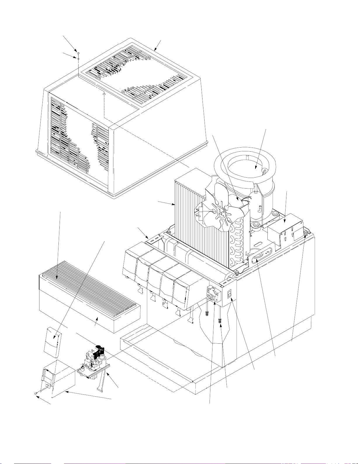
HOOD RETAINING
SCREW
O-RING
HOOD
CUP REST
KEYED LOCKOUT SWITCH
CONDENSER
DISPENSING VALVES
FLAVOR DECAL
PANEL
COIL
CONDENSER
FAN MOTOR
REFRIGERATION
COMPRESSOR
ICE BANK
CONTROL
301137000
DRIP TRAY
DISPENSING VALVE
COVER RETAINING
SCREW
FIGURE 4. DISPENSER COMPONENTS (SIX-FLAVOR UNIT SHOWN)
DISPENSING VALVE
DISPENSING
VALVE COVER
SHIPPING
NUT (4)
WATER
FILL HOLE
UNIT POWER
SWITCH
SYRUP, CARB AND PLAIN
WATER INLET TUBES
DISPENSING VALVE
MOUNTING BLOCK
16
Page 21

Adjusting Remote Carbonator CO2 Regulator.
Adjust remote carbonator CO2 regulator as instructed in manual provided with the carbonator.
Adjusting Syrup Supplies CO2 Regulator.
SUGAR SYRUP TANKS SYSTEM CO2 REGULATOR
Adjust syrup tanks system CO2 regulator to a minimum of 45-psi.
SYRUP PUMPS (BAG-IN-BOX SYSTEM) CO2 REGULATOR
Adjust the syrup pumps CO
ON THE SYRUP PUMPS.
regulator to 70-psi. DO NOT EXCEED MAXIMUM CO2 PRESSURE SPECIFIED
2
ADJUSTING DISPENSING VALVES FOR WATER FLOW RA TE
The dispensing valves adjustable water flow controls are factory adjusted and should require no further adjustment. If readjustment should become necessary, consult the dispensing valve manufacturer for the proper adjustment procedure.
ADJUSTING DISPENSING VALVES FOR WATER-TO-SYRUP “RATIO” (BRIX) OF
DISPENSED PRODUCT
The dispensing valves are each equipped with adjustable syrup flow controls. The Water-To-Syrup “Ratio” (Brix)
of the dispensed product is controlled by adjustment of these syrup flow controls. Consult the dispensing valve
manufacturer for the proper adjustment procedure.
CLEANING AND SANITIZING
DAILY CLEANING OF UNIT
1. Remove cup rest from the drip tray.
2. Wash drip tray in place on the Unit, then rinse drip tray with hot water allowing water to drain out through
the drain hose.
3. Wash cup rest, then rinse the cup rest with clean water. Install cup rest in the drip tray.
4. Clean all external surfaces of the Unit with a sponge. Rinse out the sponge with clean water, then wring
excess water out of the sponge and wipe off all external surfaces on the Unit. Wipe Unit dry with a clean
soft cloth. DO NOT USE ABRASIVE CLEANERS.
5. Remove nozzle and syrup diffusers from the dispensing valves. Place nozzles and syrup diffusers in sanitizing solution.
6. Wash the nozzles and syrup diffusers in sanitizing solution, then rinse them with potable water.
7. Re-install nozzles and syrup diffusers back on the dispensing valves.
SANITIZING POST-MIX SYRUP SYSTEMS
IMPORTANT: Only qualified Service Personnel should perform sanitizing procedure on the post-mix
syrup systems.
17 301137000
Page 22

The post-mix syrup systems should be sanitized every 90-days using a non-scented household liquid bleach
containing a 5.25 % sodium hypochlorite concentration. Proceed as follows to sanitize the post-mix syrup systems.
1. Disconnect syrup supplies from syrup systems.
2. Rinse quick disconnects (syrup tanks systems) or bag-in-box connectors (syrup bag-in-box systems) in
warm potable water.
STEP 1. WASH SYRUP SYSTEMS
3. Using a clean syrup tank (syrup tank system) or a five-gallon container (bag-in-box system), prepare a full
tank or container of liquid dishwasher detergent by using 70_ F (21_ C) to 100_ F (38_ C) potable water
and 0.5 oz. (15 ml) of liquid dishwasher detergent to one gallon of potable water. Stir detergent solution to
thoroughly mix the solution.
4. Syrup Tank Systems.
A. Observe and note CO2 pressure setting on the syrup tanks CO
regulator, then re-adjust CO2 regula-
2
tor to 60 to 80-psi. Pressurize syrup tank containing detergent solution to 60 to 80-psi.
B. Connect detergent solution tank, pressurized at 60 to 80-psi, into one of the syrup systems.
Bag-in Box Syrup Systems.
C. Install bag valves, cut from empty bag-in-box syrup containers, on ends of syrup containers syrup
outlet tubes connectors.
D. Place all syrup outlet tubes, with bag valves on their ends, in container containing detergent solution.
5. Flush the syrup system and dispensing valve as follows:
A. Place waste container under applicable dispensing valve.
B. Activate the dispensing valve for one minute to purge all syrup and flush out the syrup system.
C. Continue to activate the dispensing valve in cycles (“ON” for 15-seconds, “OFF”, then “ON” for
15-seconds). Repeat “ON” and “OFF” cycles for 15-cycles.
6. Connect detergent solution to the remaining syrup systems and flush syrup out of the syrup systems as
instructed in step 5 preceding.
7. Remove detergent solution source from the syrup system.
STEP 2. FLUSH SYRUP SYSTEMS
8. Syrup Tank Systems.
Connect syrup tank containing potable water, pressurized at 60 to 80-psi, into one of the syrup systems.
Bag-in-Box Syrup System.
Fill five-gallon container with potable water, then place all bag-in-box syrup containers syrup outlet tubes in
container containing potable water.
9. Flush detergent solution out of the syrup system and dispensing valve as follows:
A. Place waste container under applicable dispensing valve.
B. Activate the dispensing valve for one minute to purge all detergent solution and flush out the syrup
system.
C. Continue to activate the dispensing valve in cycles (“ON” for 15-seconds, “OFF”, then “ON” for
15-seconds). Repeat “ON” and “OFF” cycles for 15-cycles.
10. Connect potable water source to the remaining syrup systems and flush detergent solution out of the syrup
systems as instructed in step 9 preceding.
301137000
18
Page 23
11. Remove potable water source from the syrup system.
STEP 3. SANITIZE SYRUP SYSTEMS
12. Using a clean syrup tank (syrup tanks system) or a five-gallon container (bag-in-box system), prepare sanitizing solution using 70_ F (21_ C) to100_ F (38_ C) potable water and 0.5 oz. (15 ml) of non-scented
household liquid bleach that contains a 5.25 % sodium hypochlorite concentration to one gallon of potable
water. This mixture must not exceed 200 PPM of chlorine. Stir sanitizing solution to thoroughly mix.
13. Syrup Tank Systems.
Connect sanitizing solution tank, pressurized at 60 to 80-psi, into one of the syrup systems.
Bag-in-Box Syrup System.
Place all bag-in-box syrup containers syrup outlet tubes in container containing sanitizing solution.
14. Sanitize the syrup system and dispensing valve as follows:
A. Place waste container under applicable dispensing valve.
B. Activate the dispensing valve for one minute to purge all water from and install sanitizing solution in
the syrup system and dispensing valve.
C. Continue to activate the dispensing valve in cycles (“ON” for 15-seconds, “OFF”, then “ON” for
15-seconds). Repeat “ON” and “OFF” cycles for 15-cycles.
15. Repeat steps13 and 14 to flush water out of and install sanitizing solution in the remaining syrup systems
and dispensing valves.
16. Remove sanitizing solution source from the syrup system.
17. Allow sanitizing solution to remain in the syrup systems for not less than 10 or no more than 15-minutes
(max.) contact time.
STEP 4. WATER FLUSH SYRUP SYSTEMS
WARNING: Flush sanitizing solution from the syrup systems as instructed. Residual
sanitizing solution left in the syrup systems could create a health hazard.
18. Fill syrup tank (syrup tank system) or a five-gallon container (bag-in-box system) with potable water.
19. Syrup Tank Systems.
Connect syrup tank containing potable water, pressurized at 60 to 80-psi, into one of the syrup systems.
Bag-in-Box Syrup System.
Place all bag-in-box syrup containers syrup outlet tubes in container containing potable water.
20. Flush sanitizing solution from the syrup system and the dispensing valve as follows:
A. Place waste container under applicable dispensing valve.
B. Activate the dispensing valve for one minute to purge all sanitizing solution out of the syrup system
and the dispensing valve.
C. Continue to activate the dispensing valve in cycles (“ON” for 15-seconds, “OFF”, then “ON” for
15-seconds). Repeat “ON” and “OFF” cycles for 15-cycles.
21. Repeat steps 19 and 20 preceding to purge sanitizing solution out of the remaining syrup systems and
dispensing valves.
22. Remove potable water source from the syrup system.
19 301137000
Page 24
STEP 5. PURGE WATER OUT OF SYRUP SYSTEMS (RESTORE OPERATION)
23. Syrup Tank Systems.
A. Noting syrup tanks CO
tor to the observed pressure setting,
B. Connect tanks containing syrup into syrup systems.
Bag-in-Box Syrup System.
C. Remove all bag valves from bag-in-box syrup containers outlet tubes connectors.
D. Connect bag-in-box syrup containers into the syrup systems.
24. Place waste container under dispensing valves. Dispense from all dispensing valves to permit syrup to
purge all potable water from the syrup systems and the dispensing valves. Continue to dispense from the
dispensing valves until only syrup is dispensed from the syrup systems and valves.
WARNING: To avoid possible personal injury or property damage, do not attempt to
remove the syrup tank cover until CO2 pressure has been released from the tank.
25. Dispose of waste sanitizing solution in a sanitary sewer, not in a storm drain, then thoroughly rinse the inside and the outside of the container that was used for sanitizing solution to remove all sanitizing solution
residue.
regulator pressure setting observed in step 4 preceding, readjust CO2 regula-
2
CLEANING DROP-IN REFRIGERATION ASSEMBLY CONDENSER COIL
(see Figure 4)
Excessive accumulation of dust, lint, and grease on the drop-in refrigeration assembly condenser coil will restrict
air flow through the coil and cause a loss of the refrigeration cooling efficiency. Perform the following procedure
to clean the condenser coil.
1. Unplug Unit power cord from electrical outlet.
2. Remove Unit hood by removing one screw on top of the hood, then lift hood straight up off the Unit.
3. Vacuum or use a soft brush to clean the condenser coil. If available, use low-pressure compressed air.
4. Clean dust and dirt from around top of the refrigeration assembly.
5. Install hood on Unit and secure with one screw.
6. Plug Unit power cord into electrical outlet.
CHECKING ICE WATER BATH
(see Figure 4)
A ‘‘gurgle’’ heard from the Unit indicates water level in the water tank is low and more water should be added for
maximum cooling. Before adding more water, the ice water bath and the ice bank should be checked for cleanliness and the water tank coils checked for excessive mineral deposit build-up.
1. Unplug Unit power cord from electrical outlet.
2. Remove hood by removing one screw on top of the hood, then lift hood straight up off the Unit.
3. Remove plug from the drop-in refrigeration assembly platform water fill hole.
4. Using a flashlight, inspect the ice water bath and the ice bank for cleanliness. The ice water bath should be
clear and the ice bank should be free of foreign particles.
5. If cleaning of the water tank is necessary, refer to CLEANING WATER TANK in this section.
6. Fill the water tank with clean water to top of the stainless steel coils located inside the tank. USE
LOW-MINERAL-CONTENT WATER WHERE A LOCAL WATER PROBLEM EXISTS.
301137000
20
Page 25
7. Install plug in the water fill hole.
8. Install the Unit hood and secure with one screw.
9. Plug Unit power cord into electrical outlet.
CLEANING WATER T ANK
(see Figure 4)
1. Unplug Unit power cord from electrical outlet.
2. Extend the water tank drain hose to a permanent drain or waste receptacle. Remove plug from end of the
drain hose and allow water to drain from the water tank.
3. Remove Unit hood by removing one screw on top of the hood, then lift the hood straight up off the Unit.
4. Unplug the drop-in refrigeration assembly power cord from the Unit power cord and the electric dispensing
valves transformer power cord socket connector from the Unit wiring harness mating male connector.
5. Remove four hex nuts securing the drop-in refrigeration assembly in the Unit lower housing, then lift the
refrigeration assembly up out of the lower housing.
CAUTION: Never use an ice pick or other instrument to remove ice from drop-in
refrigeration assembly evaporator coils. Such practice can result in punctured refrigeration
circuit.
6. Allow the ice bank to melt. Hot water may be used to speed up melting of the ice.
7. Use a fiber brush and carefully clean mineral deposit build-up from the agitator motor shaft and the ice
bank sensing bulb.
8. Wash inside of the water tank and the drop-in refrigeration assembly evaporator coils, then rinse water tank
and coils with clean water.
9. Install plug in end of the water tank drain hose.
10. Install drop-in refrigeration assembly in the Unit lower housing by reversing the removal procedure. MAKE
SURE FOUR HEX NUTS ARE INSTALLED TO SECURE THE DROP-IN REFRIGERATION ASSEMBLY
IN THE LOWER HOUSING.
11. Remove water fill hole plug from the drop-in refrigeration assembly platform.
12. Fill the water tank with clean water to top of the stainless steel coils located inside the water tank. USE
LOW-MINERAL-CONTENT WATER WHERE A LOCAL WATER PROBLEM EXISTS.
13. Install plug in the water fill hole.
14. Install hood on the Unit and secure with screw.
15. Plug Unit power cord into electrical outlet.
REMOTE CARBONATOR WATER PUMP YEARLY MAINTENANCE OR
AFTER WATER SYSTEM DISRUPTIONS
WARNING: The remote carbonator water pump water inlet strainer screen and the double
liquid check valve must be inspected and cleaned at least once a year under normal
circumstances, and after any disruptions (plumbing work, earthquake, etc.) to the water
supply system that might cause turbulent (erratic) flow of water through the system. A carbonated
water pump with no screen or a defective screen in the strainer would allow foreign particles to
foul the double liquid check valve. CO2 gas could then back flow into the water system and create
a health hazard in the water system.
The remote carbonator water pump water inlet strainer screen and the double liquid check valve must be inspected and cleaned at least once a year under normal circumstances and after any water system disruption
(plumbing work, earthquake, etc.). Refer to manual provided with the remote carbonator for servicing procedure.
21 301137000
Page 26
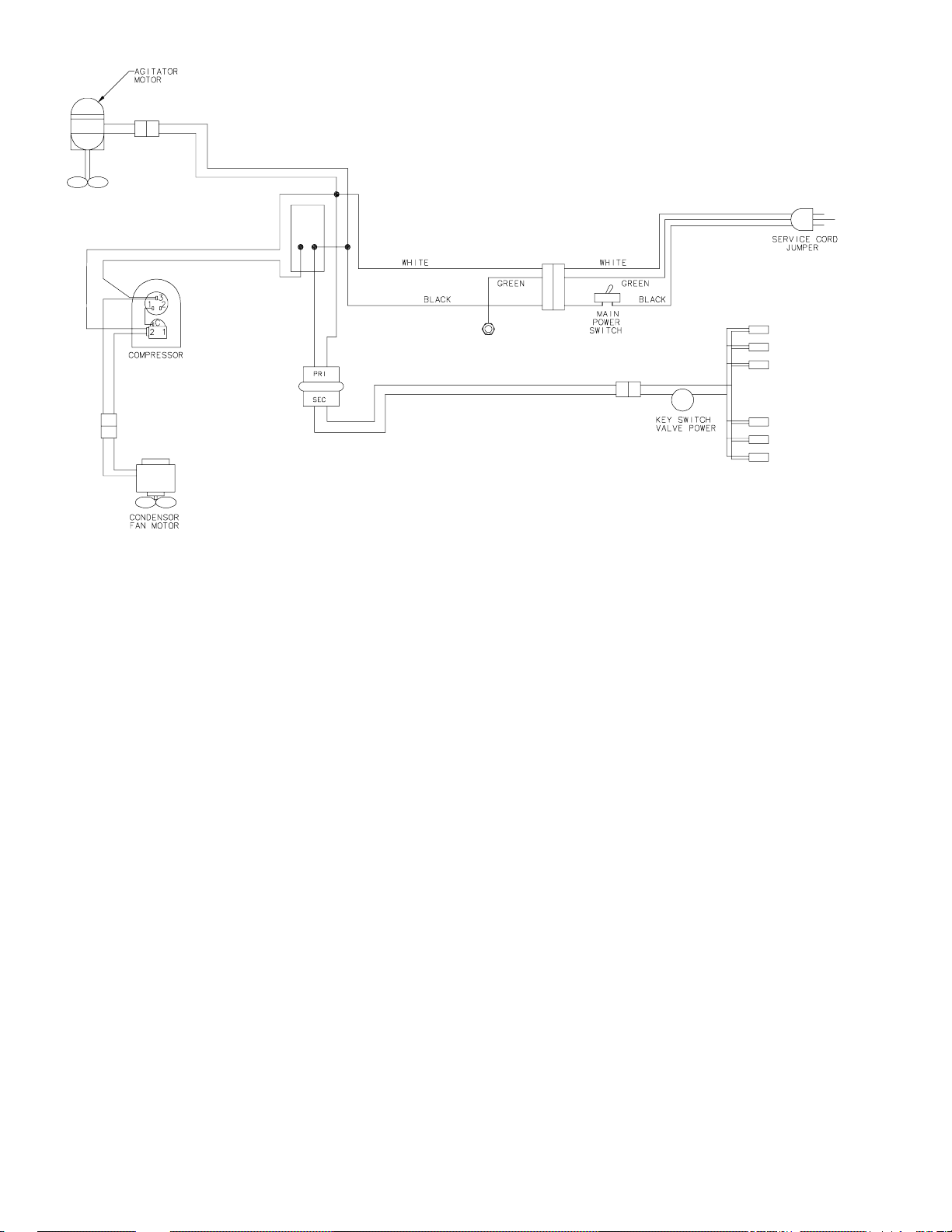
FIGURE 5. WIRING DIAGRAM
301137000
22
Page 27
TROUBLESHOOTING
IMPORTANT: Only qualified personnel should service internal components or electrical wiring.
WARNING: If repairs are to be made to a product system, remove quick disconnects from
the applicable product tank, then relieve the system pressure before proceeding. If repairs
are to be made to the CO
system, stop dispensing, shut off the CO
2
system pressure before proceeding. If repairs are to be made to the refrigeration system, make sure
electrical power is disconnected from the unit.
Trouble Probable Cause Remedy
TROUBLESHOOTING UNIT
supply, then relieve the
2
WATER-TO-SYRUP ‘‘RATIO’’
TOO LOW OR TOO HIGH.
ADJUSTMENT OF
DISPENSING VALVE SYRUP
FLOW REGULATOR DOES
NOT INCREASE TO DESIRED
WATER-TO-SYRUP ‘‘RATIO’’.
A. Dispensing valve syrup flow
control not properly adjusted.
B. Syrup Tanks System.
CO2 gas pressure to syrup
A. Adjust Water-to-Syrup ‘‘Ratio’’ of
dispensed drink as instructed.
B. Adjust CO2 regulator for syrup
tanks as instructed.
tanks insufficient to push syrup
out of tank.
Bag-In-Box System.
CO2 gas pressure to syrup
Adjust syrup pumps CO
regulator as instructed.
pumps insufficient to operate
syrup pumps.
A. No syrup supply. A. Replenish syrup supply.
B. Syrup Tanks System.
Syrup tanks CO2 regulator out
B. Adjust syrup tanks CO2 regulator
as instructed.
of adjustment.
Syrup Bag-In-Box System.
Syrup pumps CO2 regulator
Adjust syrup pumps CO
regulator as instructed.
out of adjustment.
2
2
C. Dispensing valve syrup flow
control or syrup line restricted.
C. Sanitize syrup system as
instructed.
D. Improper syrup Baume. D. Replace syrup supply.
E. Inoperative dispensing valve
syrup flow control.
F. Tapered nylon washer inside
tube swivel nut connector
E. Repair dispensing valve syrup
flow control
F. Replace tapered nylon washer
and make sure it seats properly.
distorted from being over
tightened restricting syrup flow.
23
301137000
Page 28
Trouble RemedyProbable Cause
ADJUSTMENT OF
DISPENSING VALVE SYRUP
FLOW REGULATOR DOES
NOT DECREASE TO
DESIRED
WATER–TO–SYRUP ‘‘RATIO’’.
DISPENSED PRODUCT
CARBONATION TOO LOW.
DISPENSED PRODUCT
COMES OUT OF
DISPENSING VALVE CLEAR
BUT FOAMS IN CUP OR
GLASS.
A. Dirty or inoperative dispensing
valve syrup flow control.
A. Disassemble and clean
dispensing valve syrup flow
control.
A. Carbonator CO2 regulator out
of adjustment for existing
water conditions or
A. Adjust carbonator CO2 regulator
(Reference manual provided with
carbonator).
temperature.
B. Air in carbonator tank. B. Vent air out of carbonated water
tank by dispensing from
dispensing valve to make
carbonator water pump motor
cycle on.
C. Water, oil, or dirt, in CO
supply.
2
C. Remove contaminated CO2.
Clean CO2 system (lines,
regulators, etc.) using a mild
detergent. Install a clean CO
2
supply.
A. Oil film or soap scum in cups
A. Use clean cups or glasses.
or glasses.
DISPENSED PRODUCT
PRODUCES FOAM AS IT
LEAVES DISPENSING VALVE.
B. Ice used for finished drink is
sub-cooled.
B. Do not use ice directly from
freezer. Allow ice to become ‘‘wet’’
before using. (Refer to following
NOTE).
NOTE: Crushed ice also causes dispensing problems. When finished
drink hits sharp edges of ice, carbonation is released from dispensed
drink.
A. Recovery rate of refrigeration
A. Allow ice bank to recover.
system exceeded, ice bank
depleted.
CAUTION: The refrigeration assembly condenser coil must be cleaned
every 30-days. Excessive accumulation of dust, lint, and grease on the
condenser coil will restrict cooling air flow through the coil and cause
the refrigeration system to overheat. Operating the refrigeration system
in an overheated condition will eventually lead to refrigeration
compressor failure and will automatically void the factory warranty.
B. Condenser coil plugged. B. Clean condenser coil as
instructed.
C. Carbonator CO2 regulator
pressure too high for existing
water conditions or
C. Reduce carbonator CO2 regulator
pressure setting. Reference
manual provided with carbonator.
temperature.
D. Dispensing valve restricted or
dirty.
24301137000
D. Sanitize syrup system as
instructed.
Page 29
Trouble RemedyProbable Cause
DISPENSED PRODUCT
PRODUCES FOAM AS IT
LEAVES DISPENSING VALVE.
(CONT’D)
NO PRODUCT DISPENSED
FROM ALL DISPENSING
VALVES.
E. Tapered nylon washer inside
carbonated water line swivel
E. Replace nylon washer. Make sure
it is properly seated.
nut connector distorted
restricting carbonated water
flow.
F. Dirty water supply. F. Check water filter. Replace
cartridge. (see NOTE)
NOTE: If water supply is dirty, be sure to flush the lines and the remote
carbonator completely. It may be necessary to disconnect lines from
the carbonated water tank, invert the tank, and flush the tank and all
lines to remove any foreign particles or dirt.
A. No electrical power to Unit. A. Plug in Unit power cord.
B. Unit power switch in “OFF”
position.
C. Dispensing valves keyed
lock-out switch in ‘‘OFF’’
B. Place Unit power switch in “ON”
position.
C. Place keyed lock-out switch in
‘‘ON’’ position.
position.
D. Disconnected dispensing
valves power cord.
E. Disconnected or broken wiring
D. Connect dispensing valves power
cord.
E. Connect or replace wiring.
to dispensing valves.
F. Inoperative 115/24
transformer.
NO PRODUCT DISPENSED
A. Broken or disconnected wiring. A. Repair or connect wiring.
FROM ONE DISPENSING
VALVE.
B. Inoperative dispensing valve. B. Repair dispensing valve.
ONLY CARBONATED WATER
A. Out of syrup . A. Replenish syrup supply.
DISPENSED.
B. Inoperable dispensing valve. B. Repair dispensing valve.
C. Dispensing valve syrup flow
control not properly adjusted.
D. Dispensing valve syrup flow
control or syrup lines
restricted.
ONLY SYRUP DISPENSED. A. Plain water inlet supply line
shutoff valve closed.
B. Carbonator power cord
unplugged from electrical
outlet.
F. Replace transformer.
C. Adjust dispensing valve syrup
flow control (Water-to-Syrup
‘‘Ratio’’) as instructed.
D. Sanitize syrup system as
instructed.
A. Open plain water inlet supply line
shutoff valve.
B. Plug carbonator power cord into
electrical outlet.
C. Carbonator not operating. C. Repair carbonator (refer to
manual provided with carbonator).
25
301137000
Page 30
Trouble RemedyProbable Cause
TROUBLESHOOTING REFRIGERATION SYSTEM
COMPRESSOR DOES NOT
OPERATE.
A. Ice bank sufficient. A. Refrigeration not called for.
B. Unit power cord unplugged,
Unit power switch in “OFF”
position, or drop-in
refrigeration assembly power
cord unplugged.
C. No power source. Blown fuse
or tripped circuit breaker.
D. Inoperative Unit power switch
or Unit power cord unplugged.
E. Low voltage. E. Voltage must be at least 103 volts
F. Loose, disconnected, or
broken wiring.
G. Overload protector cut out,
overheated compressor, or
condenser fan motor not
operating.
B. Plug in Unit power cord or place
Unit power switch in “ON”
position..
C. Replace fuse or reset circuit
breaker. (Note; Fuse or circuit
breaker are not part of Unit).
D. Replace power switch or plug Unit
power cord into electrical outlet.
at compressor terminals when
compressor is trying to start.
F. Tighten connections or replace
broken wiring.
G. Compressor will cool enough to
restart. Do not overdraw cooling
capacity of Unit. Refer to
‘‘CONDENSER FAN MOTOR
NOT OPERATING’’ in this
section.
COMPRESSOR WILL NOT
STOP AFTER SUFFICIENT
ICE BANK IS PRODUCED.
COMPRESSOR OPERATES
CONTINUOUSLY BUT DOES
NOT FORM SUFFICIENT ICE
BANK.
H. Inoperative overload protector
or start relay.
I. Inoperative ice bank control. I. Replace ice bank control.
J. Inoperative compressor. J. Call Service Person.
A. Ice bank control cap tube
kinked or broken.
B. Ice bank control stuck in
closed position.
A. Cooling capacity is exceeded
by over-drawing.
B. Unit located in excessively hot
area or air circulation through
condenser coil is restricted.
NOTE: Ice bank freezes from bottom of evaporator coil upward. A
refrigerant leak or insufficient charge might show an ice bank at
bottom and not at top of evaporator coil.
NOTE: If overload protector cuts out compressor, condenser fan motor
will continue to operate; otherwise; troubleshooting condenser fan
motor problems is same as for ‘‘COMPRESSOR DOES NOT OPERATE’’
paragraph plus the following:
H. Replace inoperative part.
A. Replace ice bank control.
B. Replace ice bank control.
A. Reduce amount of drinks drawn
per given time.
B. Relocate Unit or check, and if
necessary, clean condenser coil
as instructed.
CONDENSER FAN MOTOR
NOT OPERATING.
A. Jumper cord loose or
disconnected.
B. Fan blade obstructed. B. Remove obstructions.
26301137000
A. Tighten connections or replace
cord.
Page 31
Trouble RemedyProbable Cause
CONDENSER FAN MOTOR
NOT OPERATING. ((CONT’D)
AGITATOR MOTOR NOT
OPERATING.
C. Inoperative condenser fan
motor.
C. Replace condenser fan motor as
instructed.
A. Normal condition. A. Agitator motor does not operate
all the time (see NOTE below).
B. Unit power cord or
B. Connect power cord.
refrigeration assembly power
cord unplugged.
C. No power source. Blown fuse
or tripped circuit breaker.
C. Replace fuse or reset circuit
breaker. (Note: Fuse or circuit
breaker are not part of Unit.)
D. Agitator motor propeller
D. Remove obstructions.
obstructed.
E. Loose, disconnected, or
broken wiring.
E. Tighten connections or replace
broken wiring.
F. Inoperative agitator motor. F. Replace agitator motor as
instructed.
27
301137000
Page 32

Page 33

WARRANTY
IMI Cornelius Inc. warrants that all equipment and parts are free from defects in material and workmanship
under normal use and service. For a copy of the warranty applicable to your Cornelius, Remcor or Wilshire
product, in your country, please write, fax or telephone the IMI Cornelius office nearest you. Please provide the
equipment model number, serial number and the date of purchase.
IMI Cornelius Offices
AUSTRALIA D P.O. 210, D RIVERWOOD, D NSW 2210, AUSTRALIA D (61) 2 533 3122 D FAX (61) 2 534 2166
D AM LANGEN FELDE 32 D A-1222 D VIENNA, AUSTRIA D (43) 1 233 520 D FAX (43) 1-2335-2930
AUSTRIA
D BOSKAPELLEI 122 D B-2930 BRAASCHAAT, BELGIUM D (32) 3 664 0552 D FAX (32) 3 665 2307
BELGIUM
D RUA ITAOCARA 97 D TOMAS COELHO D RIO DE JANEIRO, BRAZIL D (55) 21 591 7150 D FAX (55) 21 593 1829
BRAZIL
ENGLAND
D TYTHING ROAD ALCESTER D WARWICKSHIRE, B49 6 EU, ENGLAND D (44) 789 763 101 D FAX (44) 789 763 644
D 71 ROUTE DE ST. DENIS D F-95170 DEUIL LA BARRE D PARIS, FRANCE D (33) 1 34 28 6200 D FAX (33) 1 34 28 6201
FRANCE
D CARL LEVERKUS STRASSE 15 D D-4018 LANGENFELD, GERMANY D (49) 2173 7930 D FAX (49) 2173 77 438
GERMANY
D 488 MESSOGION AVENUE D AGIA PARAS KEVI D 153 42 D ATHENS, GREECE D (30) 1 600 1073 D FAX (30) 1 601 2491
GREECE
KONG D 1104 TAIKOTSUI CENTRE D 11-15 KOK CHEUNG ST D TAIKOKTSUE, HONG KONG D (852) 789 9882 D FAX (852) 391 6222
HONG
D VIA PELLIZZARI 11 D 1-20059 D VIMARCATE, ITALY D (39) 39 608 0817 D FAX (39) 39 608 0814
ITALY
ZEALAND D 20 LANSFORD CRES. D P.O. BOX 19-044 AVONDALE D AUCKLAND 7, NEW ZEALAND D (64) 9 8200 357 D FAX (64) 9 8200 361
NEW
SINGAPORE
SPAIN
USA
D 16 TUAS STREET D SINGAPORE 2263 D (65) 862 5542 D FAX (65) 862 5604
D POLIGONO INDUSTRAIL D RIERA DEL FONOLLAR D E-08830 SANT BOI DE LLOBREGAT D BARCELONA, SP AIN D (34) 3 640 2839 D FAX (34) 3 654 3379
D ONE CORNELIUS PLACE D ANOKA, MINNESOTA D (612) 421-6120 D FAX (612) 422-3255
LD004
4/21/98
301137000 28
Page 34

THIS PAGE LEFT BLANK INTENTIONALLY
29 301137000
Page 35
IMI CORNELIUS INC.
CORPORATE HEADQUARTERS:
One Cornelius Place
Anoka, Minnesota 55303-6234
(612) 421-6120
(800) 238-3600
 Loading...