

Page 1
IMI CORNELIUS INC.
One Cornelius Place
Anoka, MN 55303–6234
Telephone (800) 238–3600
Facsimile (612) 422–3246
BEVERAGE DISPENSING SUPPORT SYSTEM ASSEMBLY (MODEL NO.
2232MS) INSTALLATION AND SERVICE MANUAL
MANFACTURED
BY
IMI CORNELIUS INC.
ANOKA, MINNESOTA 55303–1592
BEVERAGE CONTROL PANEL ASS’Y
Manual Part No. 0713
June 5, 1991
Revised: April 23, 1992
Control Code A
THIS DOCUMENT CONTAINS IMPORTANT INFORMATION
This Manual must be read and understood before the installation and operation of this Equipment.
IMI Cornelius Inc. 1990–92 Printed in U.S.A.
Page 2

GENERAL DESCRIPTION
Warranty Registration Data
(to be filled out by customer)
Model Number;
Serial Number;
Install Date;
Local Authorized
Service Center;
GENERAL WARRANTY POLICY
IMI Cornelius Inc; warrants that all equipment and
parts are free from defects in material and
workmanship under normal use and service, AS
MORE EXPRESSLY DEFINED AND LIMITED BY
SPECIFIC WARRANTIES COVERING EACH
PRODUCT.
TERMS AND CONDITIONS
PRICES...All prices are F.O.B. factory. Taxes
imposed by any present or future federal, state or
local laws, if paid by us, will be charged to purchaser.
Title and risk of loss to equipment pass to purchaser
upon delivery to carrier.
Shipments of returned merchandise sent collect will
not be accepted. Used or discontinued equipment
will not be accepted for credit under any
circumstances. Item returned to IMI Cornelius Inc;
for credit or reimbursement, having a value of less
the 25.00 dollars will not receive credit.
CLAIMS...In the event of shortage, notify carrier as
well as us immediately. In the event of damage,
notify carrier. We are not responsible for damage
occurring in transit, but will gladly render assistance
necessary to pursue your claim. Merchandise must
be inspected for concealed damage within 15 days of
receipt.
ORDERING INFORMATION
Please check the part numbers carefully when
ordering. Be sure to include: Quantity, Part. No.
Description, and How to Ship––if you have specific
routing plans.
TERMS...Terms of net thirty (30) days from date of
invoice will be gladly extended to those customers of
known and acceptable financial standing. Otherwise,
orders must be accompanied by cash. A service
charge of 11/2% per month, which is an effective
annual percentage rate of 18%, will be charged for
invoices not paid within thirty days, but in no event
will the monthly service charge exceed 1/12 of the
annual percentage rate allowable under applicable
state laws.
RETURNED GOODS...Merchandise must not be
returned without prior approval or consent, which will
be given or withheld at our sole discretion. (All
returned merchandise must be sent freight
prepaid to IMI Cornelius Inc; Anoka, Minnesota).
If the merchandise is in a new, unused condition and
is in its original carton with all the original packing
and is a configuration appearing in our current
catalog, it will be accepted back (subject to prior
approval as stated above) and a credit allowed
amounting to the original selling price or current
selling price, whichever is lower, less the restocking
charge indicated below.
Note: quantity prices may be available on spare
parts. Save money by ordering larger quantities
or bulk packaging on specific items shipped
from Anoka.
Compare quality, performance and prices. Then
consolidate and simplify your ordering procedure by
ordering current service parts from IMI Cornelius Inc;
located nearest to your area.
To reduce processing and shipping time please
submit separate orders for service parts, rather than
combine orders with equipment.
SHIPPING INFORMATION
Unless otherwise instructed, all merchandise will be
shipped as follows:
0–150 Lbs. (0–68 KG) United Parcel Service
If returned goods are received by Cornelius: Within
60 days of invoice date –– 10% of applicable selling price.
Within 61–120 days of invoice date –– 20% of applicable selling price.
Over 120 days of invoice date –– 30% of applicable
selling price.
Over 150 Lbs. (68 KG) Truck
Cornelius shall select point of origin for shipments to
give the most efficient service. Freight charges are
from manufacturing point.
1 0713
Page 3

COMPLETE SERVICE
Your trained Cornelius Sales Person stands ready to serve you with ordering and technical assistance.
He can also offer you success proven merchandising ideas and placement programs that will help you to
locate Cornelius beverage equipment in retail accounts. Complete repair and installation service by factory trained personnel is available at Authorized Service Centers. Addresses are available at your request.
Spare parts may also be ordered from our Authorized
Service Centers.
HOME OFFICES AND MANUFACTURING
IMI Cornelius Inc.
One Cornelius Place
Anoka, Minnesota 55303-1592
(612) 421-6120
800-238-3600
FAX (612) 422-3255
Our 800 number access’ the nearest Distribution Center for sales assistance.
DISTRIBUTION CENTERS
NORTHWEST: IMI Cornelius Inc.
One Selina Drive
Albany, New York 12205
(518) 869-6606
FAX 518-869-9038
800-238-3600
SOUTHEAST: IMI Cornelius Inc.
6150-D LaGrange Blvd.
Atlanta, Georgia 30336
(404) 349-0412
FAX 404-346-7054
800-238-3600
SOUTHWEST: IMI Cornelius Inc.
7427 Tower
Ft. Worth, Texas 76118
(817) 654-3888
FAX 817-590-9639
800-238-3600
WEST: IMI Cornelius Inc.
2089 Burroughs Avenue
San Leandro, California 94577
(510) 351-0961
FAX 510-351-2623
16112
Page 4

TABLE 1. SPECIFICATIONS
Model Numbers (Standard Assemblies W/O Optional Kits)
Domestic Units:
Beverage Control Panel (one carbonator) Requiring Connection to one Post-Mix Dispenser 1416
Beverage Control Panel (two carbonator) Requiring Connection to Two Post-Mix Dispenser 0516
Export Units:
Beverage Control Panel (one carbonator) Requiring Connection to One Post-Mix Dispenser 1548
Beverage Control Panel (two carbonator) Requiring Connection to Two Post-Mix Dispenser 0187
Overall Dimension:
Width 50.5 inches (12.827 M)
Height 91 inches (23.114 M)
Depth 19.5 inches (495.3 MM)
Shipping Weights (approximate):
Beverage Control Panel (one carbonator) 363 Pounds (164.7 KG)
Beverage Control Panel (two carbonator) 395 Pounds (179.17 KG)
Water Pressure Requirements (see note) 45 to 75–PSI (3.10 to 5.17 BARS)
Ambient Operating Temperature 40F (4.44C) to 100F (37.8C)
Carbonators Electrical Requirements:
Domestic:
Operating Voltage 115VAC, 60HZ
Current Draw 6.8 Amps
Export:
Operating Voltage 230VAC, 50 HZ
Current Draw 3.3 Amps
Note: If plain water source pressure is above 75–PSI (5.17 Bars), optional Water Pressure Regulator Kit
must be installed and adjusted to 75–PSI (5.17 Bars). If water source pressure is consistently less than
45–PSI (3.10 Bars), the Optional Water Pressure Booster Kit must be installed in the system. The
Booster Kit will boost water pressure from 50 to 70–PSI (3.45 to 4.83 Bars).
3 0713
Page 5
INSTALLATION
This manual is intended to assist the installer and
service personnel in the installation, operation, and
maintenance procedures to be performed on the
Beverage Control Panel Assembly (see Figure 1 and
applicable Figure 3, 4, 5, or 6).
The Beverage Control Panel Assembly is designed
to filter, pressure regulator, and distribute plain and
carbonated water, CO2 gas, and syrup to the
Post–Mix Beverage Dispenser or dispensers and
various other equipment connected to the system.
NOTE: The Beverage Control Panel Assembly is
manufactured in America and has American
sizes on the hardware. All metric conversion are
approximate and vary in size.
NOTE: The Beverage Control Panel Assembly
was thoroughly inspected before leaving the
factory and the carrier has accepted and signed
for it. Any damage or irregularities should be
noted at the time of delivery (or not later than 15
days from date of deliver) and immediately
reported to the delivering carrier. Request a
written inspection report from Claims Inspector
to substantiate any necessary claim. File claim
with the delivering carrier, not with IMI Cornelius
Inc.
INSTALLING POST–MIX DISPENSER(S)
Refer to manual(s) provided with the Post–Mix
Dispenser(s) for installation instructions, then install
Dispenser(s) in operating location(s).
If your Beverage Control Panel Assembly is
equipped with either or both the optional air
compressor kit or the water pressure booster kit,
dedicated properly grounded electrical outlets with
proper electrical requirements must also be located
close to the Beverage Control Panel Assembly
installation location to provide electrical power.
No other electrical equipment should be connected to
these electrical circuits. ALL ELECTRICAL WIRING
MUST CONFORM TO NATIONAL AND LOCAL
ELECTRICAL CODES.
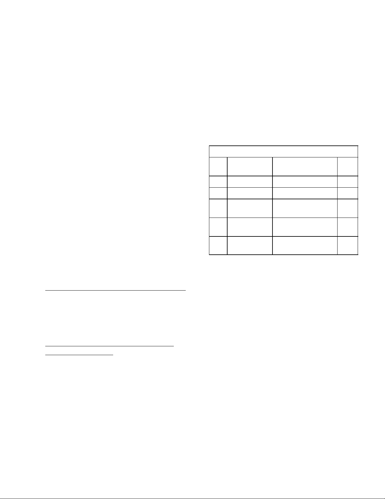
Table 2. Loose-Shipped Parts
Item
No. Part No. Name Qty.
1 300894–000 Water Surge Tank 1
2 300893–000 Strap, Surge Tank 1
3 300912 Tube Ass’y, .375 I.D.
By 56–in long
4 311304 Tapered Gasket,
Black
5 0590 Elbow Ass’y, Surge
Tank
INSTALLING WATER SURGE TANK (ITEM 1)
ON BEVERAGE CONTROL PANEL
ASSEMBLY
NOTE: It is suggested for ease of assembly, that
the loose–shipped WATER SURGE TANK (item 1)
be installed on the Beverage Control Panel
Assembly upper frame before the Panel
Assembly is set upright and fastened to the wall.
1
4
1
INSTALLING BEVERAGE CONTROL
PANEL ASSEMBLY
Your Beverage Control Panel Assembly may be
equipped with one or more of the optional kits as
shown in Figure 2. Figure 1 shows the standard
Beverage Control Panel Assembly with no optional
kits and Figure 2 shows the panel assembly with
optional kits installed.
NOTE: A dedicated and properly grounded
electrical outlet with proper electrical
requirements must be located close to the
Beverage Control Panel Assembly installation
location to provide electrical power to
(depending upon Beverage Control Panel Model
Number) one or two carbonators.
1. Install ELBOW ASS’Y SURGE TANK (item 5) in
top of WATER SURGE TANK (item 1) as shown
in Figure 17. Seal pipe thread connection with
pipe sealing compound.
2. Refer to applicable Figure 1 or 2 for water surge
tank location on Beverage Control Panel
Assembly upper frame, then remove two
self–drilling screws from frame.
3. Position water surge tank in position on
Beverage Control Panel Assembly.
4. Place STRAP, SURGE TANK (item 2) in
position around water surge tank and align
holes in strap with holes in frame where two
self–drilling screws were removed.
5. Secure strap to frame with two self–drilling
screws removed in step 2) preceding.
4
0713
Page 6

6. Connect one end of TUBE ASS’Y (item 33) to
water surge tank elbow assembly 3/8–inch flare
(5/8–18) fitting as shown in applicable Figure 3,
4, 5, or 6. Seal connection with TAPERED
GASKET, BLACK (item 4).
7. Connect other end of tube assembly to water
manifold assembly 3/8–inch flare (5/8–18) fitting
on water filter assembly (see applicable Figure
3, 4, 5, or 6). Seal connection with TAPERED
GASKET, BLACK (item 4).
FASTENING BEVERAGE CONTROL
PANEL ASSEMBLY TO WALL
WARNING: The Beverage Control
Panel Assembly must be securely
fastened to the wall before
connecting the assembly into the system.
The Beverage Control Panel Assembly must
be fastened to the wall with six fasteners
provided by the Installer) and each fastener
must be capable of resisting a 200 pound
(90.7 KG) pull. Be very careful when handling
the assembly as it is very top heavy and
could fall and cause serious personal injury
and also equipment damage.
CONNECTING SUGAR–BASE SYRUP TANKS
LINES TO BEVERAGE CONTROL
CO
2
PANEL ASSEMBLY CO
(see Figure 7)
1. Using .265 I.D. tubing, fittings, gas quick
disconnects, and tubing clamps, provided in the
installation kit, make up three gas lines to be
connected between the CO2 manifold and the
sugar–base syrup tanks.
2. Connect three gas lines swivel nut ends to CO
check valves on Beverage Control Panel
Assembly CO2 manifold. Seal connections with
white tapered gaskets.
MANIFOLD
2
2
CONNECTING DIET SYRUP TANK CO2 LINE
TO BEVERAGE CONTROL PANEL
ASSEMBLY DIET SYRUP CO
(see Figure 7)
3. Using .265 I.D. tubing, fittings, gas quick
disconnect, and tubing clamps, make up one
gas line to be connected between the Beverage
Control Panel Assembly diet–syrup tank.
4. Connect swivel nut end of gas line to check
valve on outlet of the diet–syrup tank CO
regulator. Seal connection with white tapered
gasket.
REGULATOR.
2
2
Refer to instructions in previous WARNING note and
secure Beverage Control Panel Assembly to wall as
follows:
1. Very carefully, lay panel assembly upper frame
over on its back side. Slide telescoping lower
frame up on panel assembly upper frame.
2. Very carefully, lift Beverage Control Panel
Assembly up and place in position up against
wall.
3. Using screw adjusters on bottoms of Legs,
adjust until Control Panel Assembly sits level.
4. Secure Control Panel Assembly to wall with six
fasteners provided by the installer.
5. Using .156 I.D. tubing provided in installation kit,
connect one end of tubing to vented double
check valve (see applicable Figure 3, 4, 5, or 6),
then route other end of tubing to a permanent
floor drain.
CONNECTING BEVERAGE CONTROL
PANEL ASSEMBLY TO POST–MIX
DISPENSER(S) AND OTHER EQUIPMENT TO
BE CONNECTED TO THE SYSTEM
(see Figure 7)
NOTE: The syrup, plain and carbonated water
and CO2 lines to the Post–Mix Dispenser(s) and
various other equipment at the installation site
may be routed overhead or through a floor chase
from the Beverage Control Panel Assembly.
MAKE SURE ALL LINES ARE LABELED FOR
IDENTIFICATION.
Refer to manual(s) provided with the Post–Mix
Dispenser(s) to connect plain water, carbonated
water, and syrup lines to the Dispenser(s).
Center–Island Installation with Optional Syrup Tanks
Hookup (see Figure NO TAG)
Connect CO2, plain water, carbonated water, and
syrup lines between Beverage Control Panel
Assembly, the Post–Mix Dispenser, and other
equipment to be connected to the system. Optional
syrup tanks Kit (P/N 0673) is used to connect four
syrup tanks into system.
6. Fasten tubing to frame assembly with wire ties
provided in installation kit.
Connect insulated plain water line between plain
water line connected to Post–Mix Dispenser cold
plate and the Orange Juice Dispenser.
5
0713
Page 7
Center–Island and Second Dispenser Installation
with Optional Syrup Tanks Hookup (see Figure
NO TAG)
2. Make sure all shutoff valves on water manifold
assembly and water filter assembly are in
‘‘OFF’’ position.
Connect CO2, plain water, carbonated water, and
syrup lines between Beverage Control Panel
Assembly, the Post–Mix Dispensers, and other
equipment to be connected to the system. Optional
Syrup Tanks Kit (P/N 0673) is used to connect four
syrup tanks into the system.
Connect insulated plain water line between plain
water line connected to Post–Mix Dispenser cold
plate and the Orange Juice Dispenser.
Center–Island Installation with Bulk Syrup Tank
Hookup (see Figure NO TAG).
Connect CO2, plain water, carbonated water, and
syrup lines between Beverage Control Panel
Assembly, the Post–Mix Dispenser, and other
equipment to be connected to the system.
Connect insulated plain water line between plain
water line connected to Post–Mix Dispenser cold
plate and the Orange Juice Dispenser.
Center–Island and Second Dispenser Installation
with Bulk Syrup Tank Hookup (see Figure NO TAG).
IMPORTANT: DO NOT operate carbonator(s)
water pump(s) or water pressure booster system
(if applicable) water pump with no water in the
system. Operating pumps dry will cause damage
to the pumps which will void their factory
warranty.
3. Connect plain water source line, meeting
requirements of preceding NOTE, to Beverage
Control Panel Assembly.
4. Open Beverage Control Panel Assembly plain
water source shutoff valve.
5. Beverage Control Panel Assembly equipped
with Everpure water filters (see applicable
Figure 3 or 5).
A. Connect length of garden hose to FILTER
‘‘ACTIVATION VALVE,’’ then route hose to
a permanent drain.
B. Open ‘‘ACTIVATION VALVE’’ and allow
approximately 28–gallons of water to flow
through the water filters, then close valve.
Connect CO2, plain water, carbonated water and
syrup lines between Beverage Control Panel
Assembly, the Post–Mix Dispensers, and other
equipment to be connected to the system.
Connect insulated plain water line between plain
water line connected to Post–Mix Dispenser cold
plate and the Orange Juice Dispenser.
PREPARATION FOR OPERATION
BEVERAGE CONTROL PANEL ASSEMBLY
NOTE: The Beverage Control Panel Assembly
must be connected to a water source with water
pressure between 45 and 75–PSI (3.10 and 5.17
Bars). If water pressure is over 75–PSI (5.17
Bars), an Optional Water Pressure Regulator Kit
(P/N 300919–00) must be installed. If plain water
source is below 45–PSI (3.10 Bars), an Optional
Water Pressure Booster Kit must be installed in
the system to boost water pressure to 75–PSI
(5.17 Bars).
IMPORTANT: DO NOT operate (if applicable) the
Optional Water Pressure Booster water pump
with no water connected to the Beverage Control
Panel Assembly. Operating water pump dry will
void its factory warranty.
1. Install loose–shipped water filter cartridges on
water filter assembly.
6. Standard Installation (see Figure 7).
WARNING: CO2 Displaces Oxygen.
Strict Attention must be observed in
the prevention of CO2 (carbon
dioxide) gas leaks in the entire CO2 and soft
drink system. If a CO2 gas leak is suspected,
particularly in a small area, immediately
ventilate the contaminated area before
attempting to repair the leak. Personnel
exposed to high concentration of CO2 gas
will experience tremors which are followed
rapidly by loss of consciousness and
suffocation.
Connect bulk CO2 tank CO2 supply line to barbed
fitting on CO2 manifold. Secure connection with
tubing clamp.
Installation employing the optional high–pressure
CO2 Regulator Assembly Kit (P/N 0708) (see Figure
7)
WARNING: To avoid personal injury
and/or property damage, always
secure CO2 cylinders with safety
chain to prevent them from falling over.
Should the valve become accidentally
damaged of broken off, CO2 cylinder can
cause serious personal injury.
6
0713
Page 8

A. Locate two full CO
positions next to the CO
cylinders in upright
2
mounting
2
bracket. Fasten CO2 cylinders with safety
chain.
B. Connect two CO2 lines from Beverage
Control Panel Assembly two primary CO
2
regulators to the CO2 cylinders.
7. Installation employing the Optional Water
PressureBooster System Kit (see applicable
Figure 3, 4, 5, or 6)
Note service valve on bottom of the Water Pressure
Booster System Water Tank. The water tank must be
pressurized with 40 5–PSI (2.76 .34 Bars) of
commercially dry air, CO2, or nitrogen gas through
the water tank service valve before putting system
into operation.
B. Adjust two Primary CO
regulators to
2
105–PSI (7.24 Bars). Pull up on
carbonator(s) tank(s) relief valve(s) for
approximately two seconds to bleed air
from tanks.
C. Adjust secondary CO
regulator assembly
2
CO2 regulator with 100–PSI (6.9 Bars)
gauge for sugar–base syrup tanks to
60–PSI (4.14 Bars).
D. Adjust diet syrup tank CO2 regulator with
30–PSI (2.07 Bars) gauge on secondary
CO2 regulator assembly to 12–PSI (.83
Bars).
11. The Post–Mix Dispenser(s) and entire syrup
systems should be sanitized as instructed in
manual(s) provided with Dispenser(s) before
syrup is connected into the systems.
8. Water Surge Tank (see applicable Figure 3, 4,
5,, or 6)
Note service valve on bottom of the water surge
tank. The water surge tank must be pressurized with
12 2–PSI (.83 .14 Bars) of commercially dry air,
CO2, or nitrogen gas through the water tank service
valve before putting system into operation.
9. System Connected to Bulk CO2 Supply (see
Figure 7)
A. Open shutoff valve on bulk CO2 tank.
B. Adjust CO2 regulator on bulk CO2 tank to
105–PSI (7.24 Bars). Pull up on
carbonators tanks relief valves for
approximately two seconds to bleed air
from tanks.
C. Adjust sugar–base syrup tanks CO
2
regulator with 100–PSI (6.9 Bars) gauge on
secondary CO2 regulator assembly to
60–PSI (4.14 Bars).
D. Adjust diet syrup tank CO2 regulator with
30–PSI (2.07 Bars) gauge on secondary
CO2 regulator Assembly to 12–PSI (.83
Bars).
10. System connected to two fifty pound CO
2
cylinders (see Figure 7).
A. Open CO2 cylinders valves slightly to allow
lines to slowly fill with gas, then open
valves fully to back seat valve.
Back–seating valve prevents leakage
around valve shaft.
IMPORTANT: Even though sanitizing procedure
has been performed on syrup systems during
initial installation a temporary new tubing plastic
off–taste of dispensed product may occur. If this
off–taste should occur, prepare a solution of
citric acid in proportion as instructed on the
citric acid packaging. Pump citric acid solution
through the syrup systems and all carbonated
and plain water tubes installed as part of the
system. Thoroughly flush syrup systems and all
carbonated and plain water tubes with plain
water to make sure all citric acid has been
removed.
12. Open all plain water shutoff valves on Beverage
Control Panel Assembly.
13. Check entire system for syrup, CO2 gas, and
plain and carbonated water leaks. Repair if
leaks are evident.
14. Plug carbonator(s) and Water Pressure Booster
system (if applicable) power cords into electrical
outlets.
15. If Optional Air Compressor Kit is being used and
it is desired to operate with compressed air
rather than CO2 gas pressure.
A. Plug air compressor power cord into
electrical outlet.
B. Place CO2/air switchover valve (see Figure
7) in air position.
16. Refer to manual(s) provided with the
Dispenser(s) to put Dispenser(s) into operation.
Operate all dispensing valves to bleed all air
from plain and carbonated water systems.
17. Standard Installation Connected to Bulk Syrup
Tanks (see Figure 7)
7
0713
Page 9

A. Connect bulk syrup tank into system.
B. Connect three other flavors syrup tanks
into syrup systems.
18. Installation Using Optional Syrup Tank Kit
(P/N 0673) (see Figure 7.)
A. Connect four syrup tanks into syrup
systems.
B. Connect three other flavors syrup tanks
into syrup systems.
19. Operate all Dispenser(s) dispensing valves to
bleed all air from syrup systems.
CHECKING ENTIRE SYSTEM FOR
SYRUP, CO2 GAS, AND PLAIN AND
CARBONATED WATER LEAKS
Check entire system for syrup, CO2 gas, and plain
and carbonated water leaks and repair if evident.
SEALING ENDS OF FLOOR CHASE (IF
APPLICABLE)
1. Pack ends of floor chase with paper to within
approximately six–inches from the top.
2. Seal ends of floor chase with plaster of paris
which may be purchased at a local building
materials store.
8
0713
Page 10
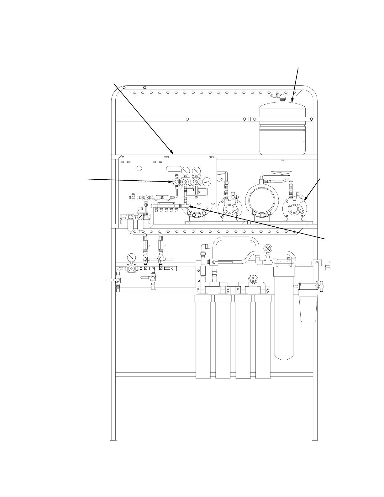
*BEVERAGE CONTROL PANEL MODEL 0817
AND 0516 ARE EQUIPPED WITH TWO CAR-
BONATOR ASSEMBLIES. MODEL 1416 AND
1548 ARE EQUIPPED WITH ONE CARBONA-
SECONDARY CO
REGULATOR PANEL ASS’Y
2
TOR ASSEMBLY.
WATER SYSTEM
SURGE TANK
CO2 SWITCHOVER
VALV E
CARBONATOR
ASS’Y(2)
PLUG
FIGURE 1. STANDARD BEVERAGE CONTROL PANEL ASS’Y
07139
Page 11
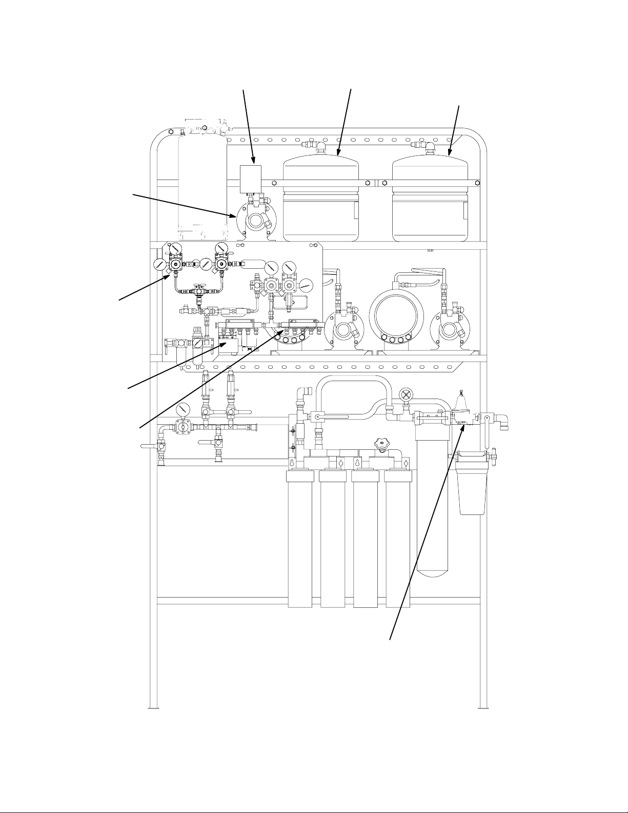
OPTIONAL WATER
PRESSURE BOOSTER
KIT
OPTIONAL PRIMARY
CO2 REGULATOR
ASS’Y KIT
PRESSURE SWITCH
WATER PRESSURE
BOOSTER SYSTEM
WATER TANK
WATER
SURGE TANK
OPTIONAL AIR
COMPRESSOR KIT
OPTIONAL SYRUP
TANKS KIT
OPTIONAL WATER
PRESSURE
REGULATOR KIT
FIGURE 2. BEVERAGE CONTROL PANEL ASSEMBLY
(WITH ALL OPTIONAL KITS INSTALLED)
10 0713
Page 12
OPTIONAL WATER
PRESSURE BOOSTER KIT
SHUTOFF
VALV E
WATER
TANK
SERVICE
VALV E
LINE LEGEND
PLAIN WATER
CARBONATED WATER
PRESSURE
SWITCH
CHECK
VALV E
WATER PUMP
(90–GPH) (341–LPH)
CARBONATED
WATER TANK
WATER PUMP
WATER
SURGE TANK
SERVICE
VALV E
TO POST–MIX
DISPENSER
NOTE: THIS TUBE ASS’Y IS
CONNECTED WHEN OPTIONAL
WATER PRESSURE BOOSTER
KIT IS NOT USED.
WATER PRESSURE
FILET BUN
STEAMER
DOUBLE VENTED
CHECK VALVE(2)
REGULATOR
(12–PSI) (.8–BARS)
TO POST–MIX
DISPENSER
CARBONATOR
CAPPED
WATER PRESSURE
GAUGE
SHUTOFF
VALVE(7)
FINE FILTERS
(TASTE AND ODOR)
(F2)
STANDARD
TUBE ASS’Y
(SEE NOTE)
FILTER
ACTIVATION
VALV E
WATER
PRESSURE
GAUGE
PRE
FILTER
(F1)
PHOSPHATE
FEEDER (F3)
COFFEE
MACHINE/SEASONAL
DRINKS
WATER PRESSURE
REGULATOR OPTIONAL
WATER SHUTOFF
VALV E
PLAIN WATER
SOURCE
(45 TO 75– PSI)
(3.1 TO 5.1 –BARS)
ICE
MACHINE
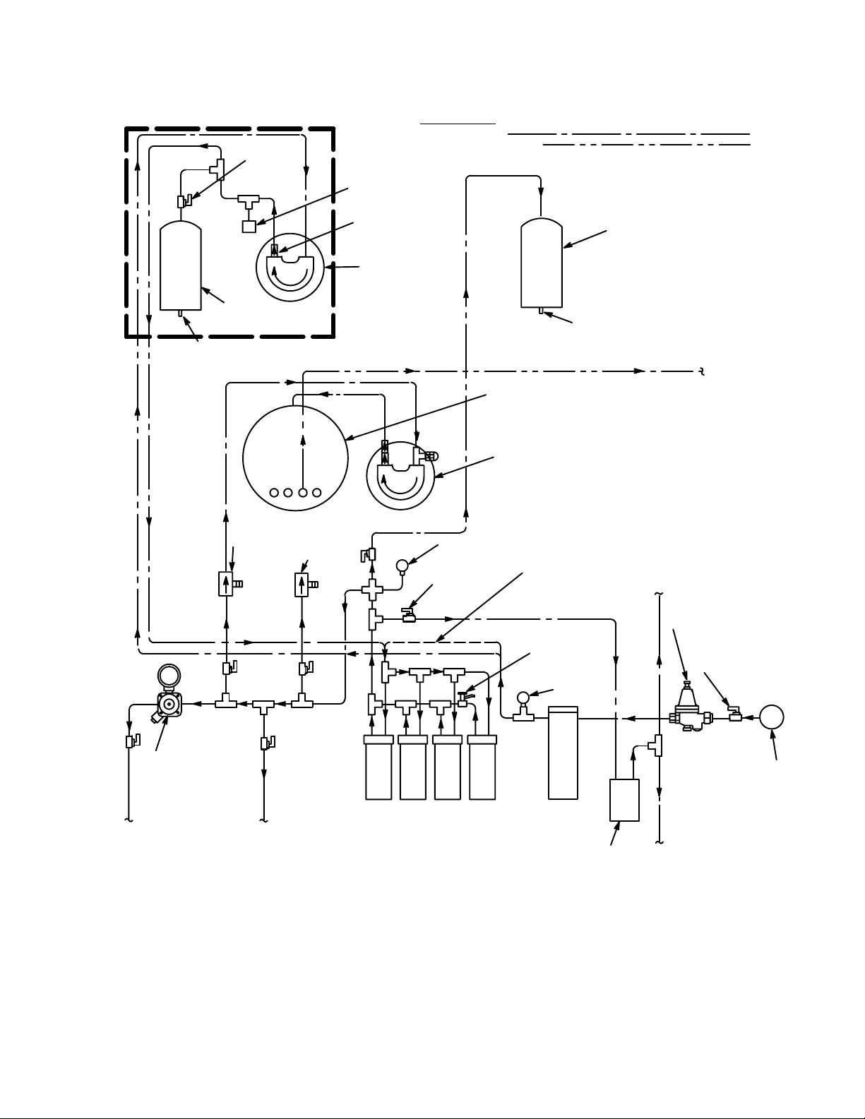
FIGURE 3. PLAIN AND CARBONATED WATER SYSTEMS FLOW DIAGRAM
W/EVERPURE WATER FILTERS (MODELS 1416 AND 1548)
071311
Page 13
OPTIONAL WATER
PRESSURE BOOSTER KIT
SHUTOFF
VALV E
WATER
TANK
SERVICE
VALV E
LINE LEGEND
PLAIN WATER
CARBONATED WATER
PRESSURE
SWITCH
CHECK
VALV E
WATER PUMP
(90–GPH) (341–LPH)
CARBONATED
WATER TANK
WATER PUMP
WATER
SURGE TANK
SERVICE
VALV E
TO POST–MIX
DISPENSER
NOTE: THIS TUBE ASS’Y IS
CONNECTED WHEN OPTIONAL
WATER PRESSURE BOOSTER
KIT IS NOT USED.
WATER PRES-
FILET BUN
STEAMER
SURE
REGULATOR
(12–PSI)
(.8–BARS)
DOUBLE VENTED
CHECK VALVE(2)
CAPPED
TO POST–MIX
DISPENSER
CARBONATOR
FINE
FILTER
WATER PRESSURE
GAUGE
SHUTOFF
VALVE(7)
STANDARD
TUBE ASS’Y
(SEE NOTE)
TASTE/ODOR
FILTER
MACHINE/SEASONAL
WATER
PRESSURE
GAUGE
PRE
FILTER
(F1)
ICE MAKER
FEEDER FILTER
COFFEE
DRINKS
WATER PRESSURE
REGULATOR OPTIONAL
WATER SHUTOFF
VALV E
PLAIN WATER
SOURCE
(45 TO 75– PSI)
(3.1 TO 5.1 –BARS)
ICE
MACHINE
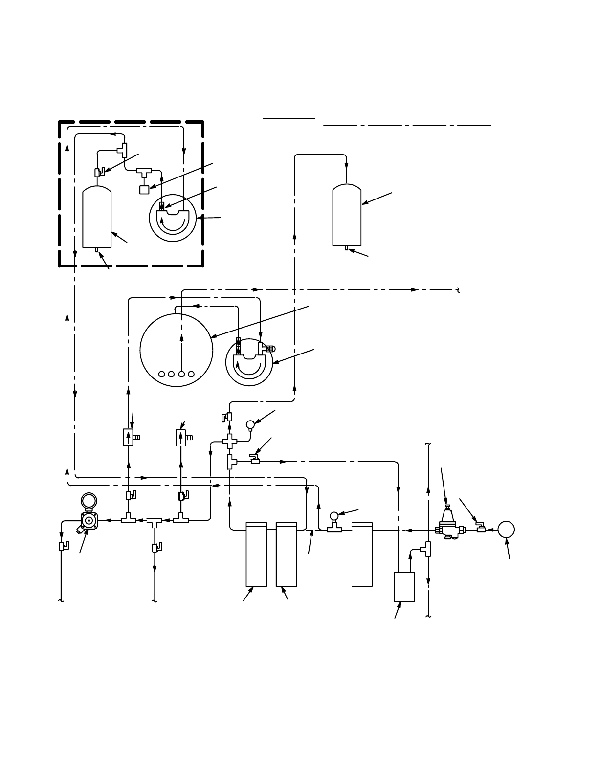
FIGURE 4. PLAIN AND CARBONATED WATER SYSTEMS FLOW DIAGRAM
W/CUNO WATER FILTERS (MODELS 1416 AND 1548)
12 0713
Page 14
OPTIONAL WATER
PRESSURE BOOSTER KIT
SHUTOFF
VALV E
WATER
TANK
SERVICE
DOUBLE VENTED
CHECK VALVE(2)
VALV E
LINE LEGEND
PLAIN WATER
CARBONATED WATER
PRESSURE
SWITCH
CHECK
VALV E
WATER PUMP
(90–GPH) (341–LPH)
NOTE: THIS TUBE ASS’Y IS
CONNECTED WHEN OPTIONAL
WATER PRESSURE BOOSTER
KIT IS NOT USED.
WATER
SURGE TANK
SERVICE
VALV E
TO POST–MIX
DISPENSER
CARBONATED
WATER TANK
WATER PUMP
WATER PRESSURE
(12–PSI) (.8–BARS)
FILET BUN
STEAMER
REGULATOR
TO POST–MIX
DISPENSER
CARBONATOR
(TASTE AND ODOR)
WATER PRESSURE
SHUTOFF
VALVE(7)
FINE FILTERS
(F2)
GAUGE
CARBONATOR
STANDARD
TUBE ASS’Y
(SEE NOTE)
FILTER
ACTIVATION
VALV E
WATER
PRESSURE
GAUGE
PRE
FILTER
(F1)
PHOSPHATE
FEEDER (F3)
COFFEE
MACHINE/SEASONAL
DRINKS
WATER PRESSURE
REGULATOR OPTIONAL
WATER SHUTOFF
VALV E
PLAIN WATER
SOURCE
(45 TO 75– PSI)
(3.1 TO 5.1 –BARS)
ICE
MACHINE
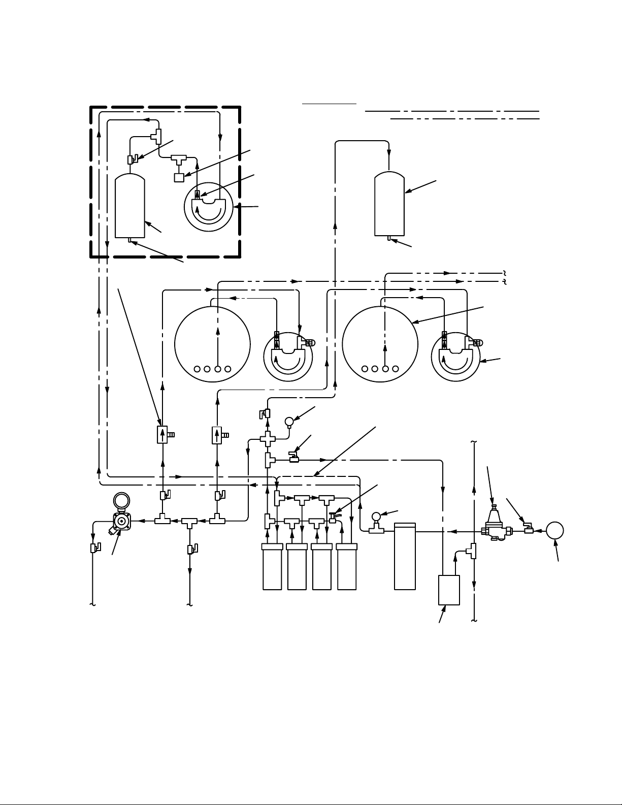
FIGURE 5. PLAIN AND CARBONATED WATER SYSTEMS FLOW DIAGRAM
W/EVERPURE WATER FILTERS (MODELS 0187 AND 0516)
071313
Page 15
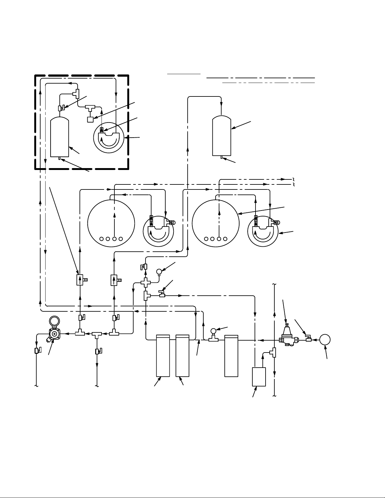
OPTIONAL WATER
PRESSURE BOOSTER KIT
SHUTOFF
VALV E
PRESSURE
SWITCH
CHECK
VALV E
LINE LEGEND
PLAIN WATER
CARBONATED WATER
WATER
SURGE TANK
WATER
TANK
DOUBLE VENTED
CHECK VALVE(2)
SERVICE
VALV E
WATER PUMP
(90–GPH) (341–LPH)
CARBONATOR
WATER PRESSURE
GAUGE
SHUTOFF
VALVE(7)
SERVICE
VALV E
CARBONATOR
MACHINE/SEASONAL
WATER
PRESSURE
GAUGE
NOTE: THIS TUBE ASS’Y IS
CONNECTED WHEN OPTIONAL
WATER PRESSURE BOOSTER
KIT IS NOT USED.
TO POST–MIX
DISPENSER
CARBONATED
WATER TANK
WATER PUMP
COFFEE
DRINKS
WATER PRESSURE
REGULATOR OPTIONAL
WATER SHUTOFF
VALV E
WATER PRESSURE
REGULATOR
(12–PSI) (.8–BARS)
FILET BUN
STEAMER
TO POST–MIX
DISPENSER
FINE
FILTER
STANDARD
TUBE ASS’Y
(SEE NOTE)
TASTE/ODOR
FILTER
PRE
FILTER
(F1)
ICE MAKER
FEEDER FILTER
PLAIN WATER SOURCE
(45 TO 75– PSI)
(3.1 TO 5.1 –BARS)
ICE
MACHINE
FIGURE 6. PLAIN AND CARBONATED WATER SYSTEMS FLOW DIAGRAM
W/CUNO WATER FILTERS (MODELS 0187 AND 0516)
14 0713
Page 16
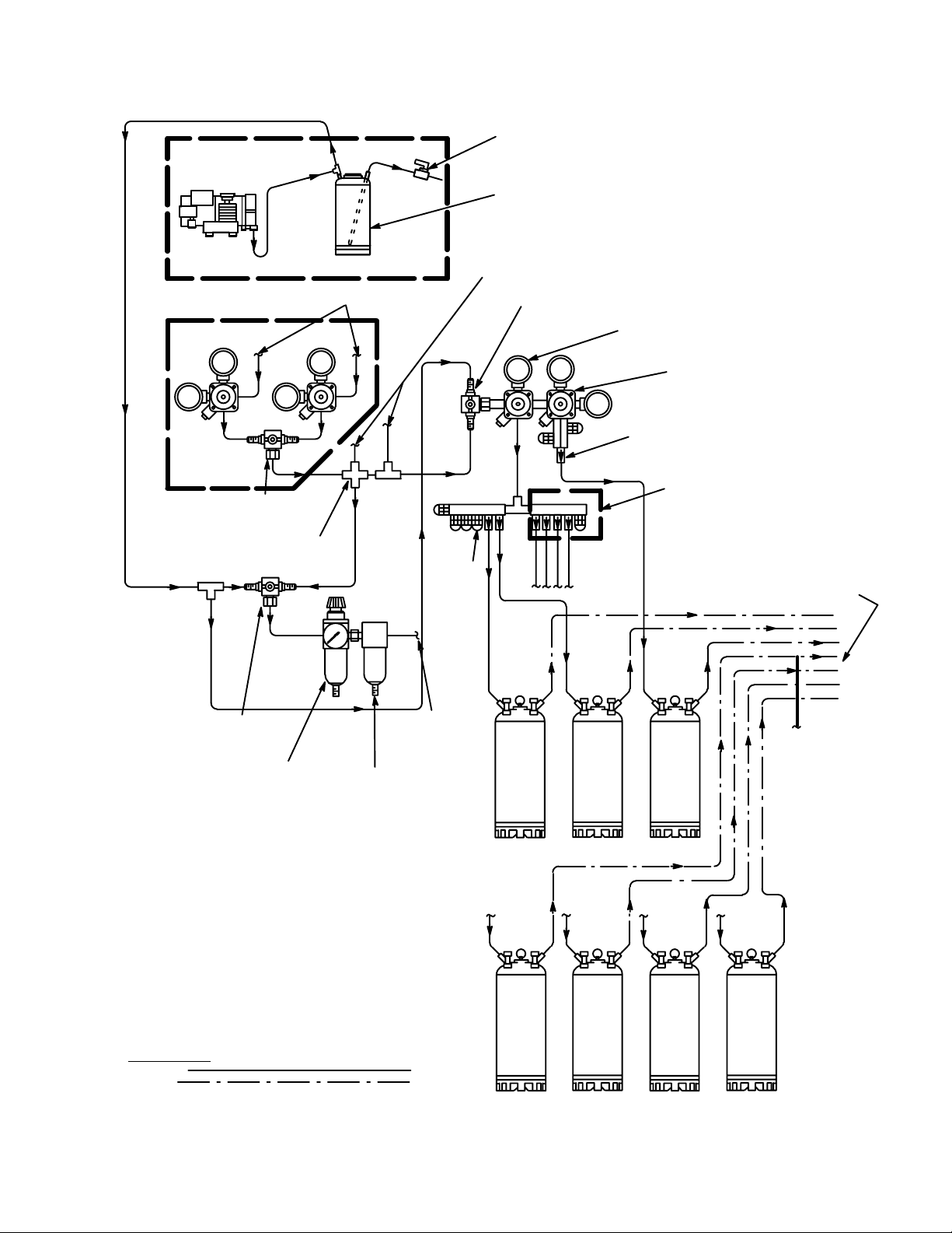
AIR COMPRESSOR KIT (OPTIONAL)
CO2 REGULATOR ASS’Y
KIT (OPTIONAL)
TO CO2 CYLINDER
CONDENSATION
DRAIN TUBE
CONDENSATION
TANK
CONNECT TO CARBONATORS
CO2/AIR CHANGEOVER
VALV E
SUGAR BASED SYRUP
(60–PSI) (4.14 BARS)
DIET SYRUP
(12–PSI) (.83 BARS
CO2 CHECK VALVE
CO2/AIR CHANGEOVER
CO2/AIR CHANGEOVER
*THE STANDARD INSTALLATION EMPLOYS
THE USE OF A BULK SYRUP TANK WHICH
IS CONNECTED TO FOUR OF THE DISPENSERS
SYRUP INLET LINES. OPTIONAL SYRUP TANKS
KIT PROVIDES THE MEANS TO CONNECT FOUR
SYRUP TANKS INSTEAD OF THE BULK SYRUP
TANK.
VALV E
BULK CO2 TANK CONNECTION
(STANDARD INSTALLATION)
VALV E
AIR PRESSURE
REGULATOR
AND COURSE
FILTER
FINE FILTER
SHAKE
MACHINE
TO
DISPENSERS
ORANGE
SPRITE
SYRUP TANK KIT (OPTIONAL)
CONNECT
TO
DISPENSING
STATIONS
FROM BULK
SYRUP TANK
DIET
(STANDARD
INSTALLATION)
LINE LEGEND
CO2/AIR
SYRUP
FIGURE 7. CO2/AIR AND SYRUP SYSTEMS FLOW DIAGRAM
071315
Page 17
16
)
1
2
3
4
5
6
7
8
9
10
11
12
13
14
15
16
17
0713
COKE
BULK
TANK
SPRITE
DIET
ORANGE
COKE
COKE
COKE
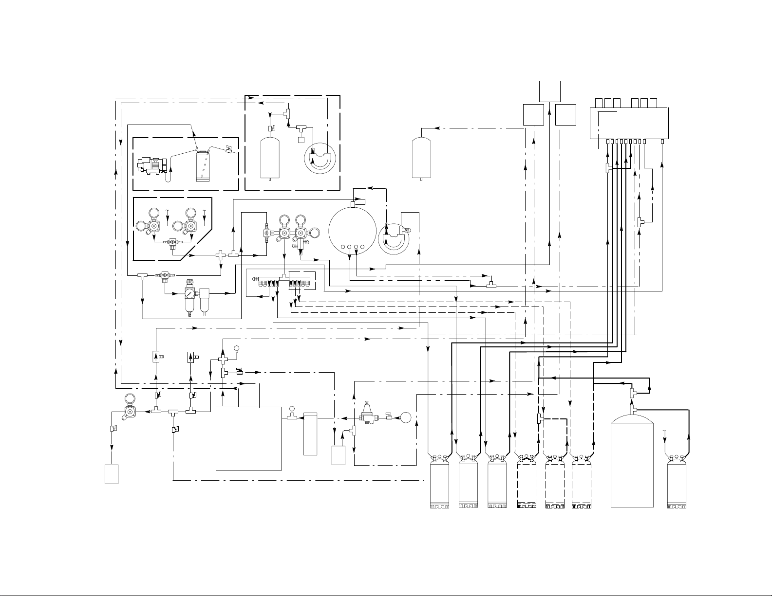
FIGURE 8. CONNECTION DIAGRAM (CENTER–ISLAND INSTALLATION WITH OPTIONAL SYRUP TANKS HOOKUP
COKE
Page 18
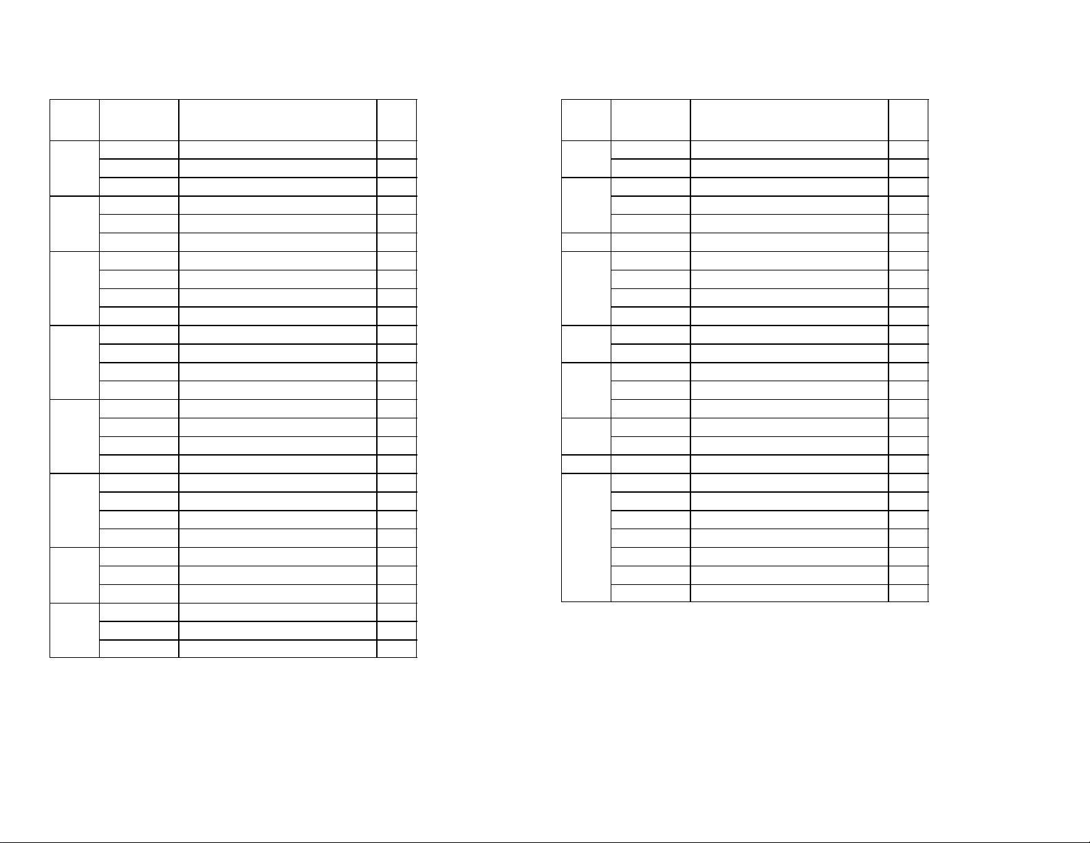
CONN
NBR Part No. DESCRIPTION QTY.
1
770409000 3/8 Swivel - 3/8 Barb Elbow 1
311304000 Gasket 1
309852000 170 Oeitker Clamp 2
2
770695000 1/2 x 3/8 x 3/8 Barb Tee 1
309852000 170 Oeitker Clamp 4
319681000 210 Oeitker Clamp 2
3
176206000 1/2 Nut 1
176205000 1/2 x 3/8 Stem 1
311304000 Gasket 1
309852000 170 Oeitker Clamp 4
4
770105000 1/4 Swivel Hose Stem 1
770101000 1/4 Swivel Nut 1
111353000 145 Oeitker Clamp 2
178025100 Gasket 1
5
770304000 1/4 x 3/8 Swivel Hose Stem 1
17
770301000 3/8 Swivel Nut 1
311304000 Gasket 1
111353000 145 Oeitker Clamp 2
6
770699000 1/2 x 1/2 x 3/8 Barb Tee 2
770423000 1/2 x 3/8 Barb Splice 1
319681000 210 Oeitker Clamp 10
309852000 170 Oeitker Clamp 6
7
770407000 3/8 x 1/4 Barb Splice 1
309852000 170 Oeitker Clamp 4
111353000 145 Oeitker Clamp 2
8
770607000 3/8 x 3/8 1/4 Barb Tee 1
309852000 170 Oeitker Clamp 4
111353000 145 Oeitker Clamp 2
CONN
NBR Part No. DESCRIPTION QTY.
9
770403000 3/8 x 3/8 Barb Splice 1
309852000 170 Oeitker Clamp 4
10
770621000 3/8 x 1/4 x 1/4 Barb Tee 1
309852000 170 Oeitker Clamp 2
111353000 145 Oeitker Clamp 4
11 Installer Supplied 1
12
770305000 3/8 Swivel Hose Barb 1
770301000 3/8 Swivel Nut 1
309852000 170 Oeitker Clamp 2
311304000 Gasket 1
13
274244000 Gas QD Slot !/4 Barb 1
111353000 145 Oeitker Clamp 2
14
274212000 Syrup QD 1/4 Flare 1
770465000 1/4 Flare x 3/8 Barb 1
309852000 170 Oeitker Clamp 2
15
770402000 1/4 x 1/4 Barb Splice 1
111353000 145 Oeitker Clamp 4
16 Installer Supplied
17
274212000 Syrup QD 1/4 Flare 1
770465000 1/4 FFL x 3/8 Barb 1
309852000 170 Oeitker Clamp 2
311035000 Strainer 1
770750010 1/4 MFL to 1/4 MPT 2
310822000 1/4 FFL to 1/4 FFl 1
178025100 Gasket 2
0713
Page 19
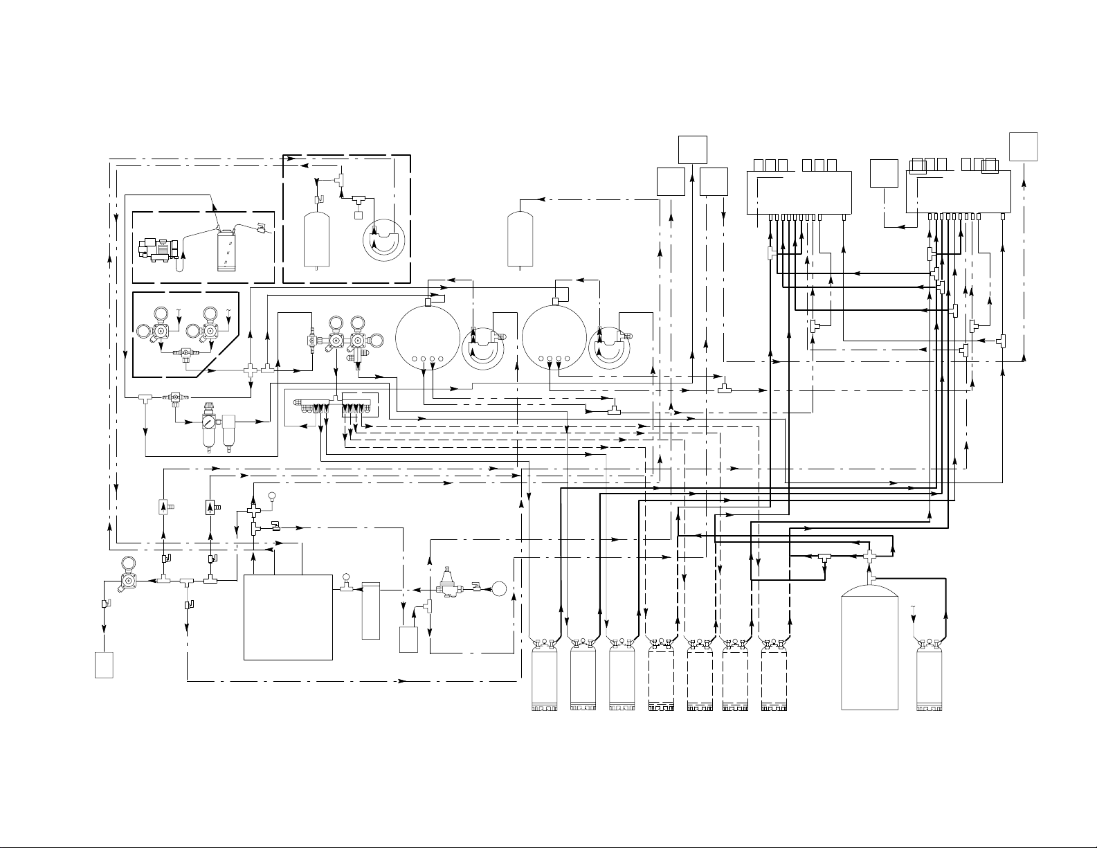
18
10
11
12
13
14
15
16
17
18
19
1
2
3
4
5
6
7
8
9
coke
1
coke
orange
diet
coke
sprite
6
partnum
SPRITE
DIET
ORANGE
COKE
COKE
COKE
COKE
FIGURE 9. CONNECTION DIAGRAM (CENTER–ISLAND AND SECOND DISPENSER
WITH OPTIONAL SYRUP TANKS HOOKUP
COKE
BULK
TANK
COKE
Page 20
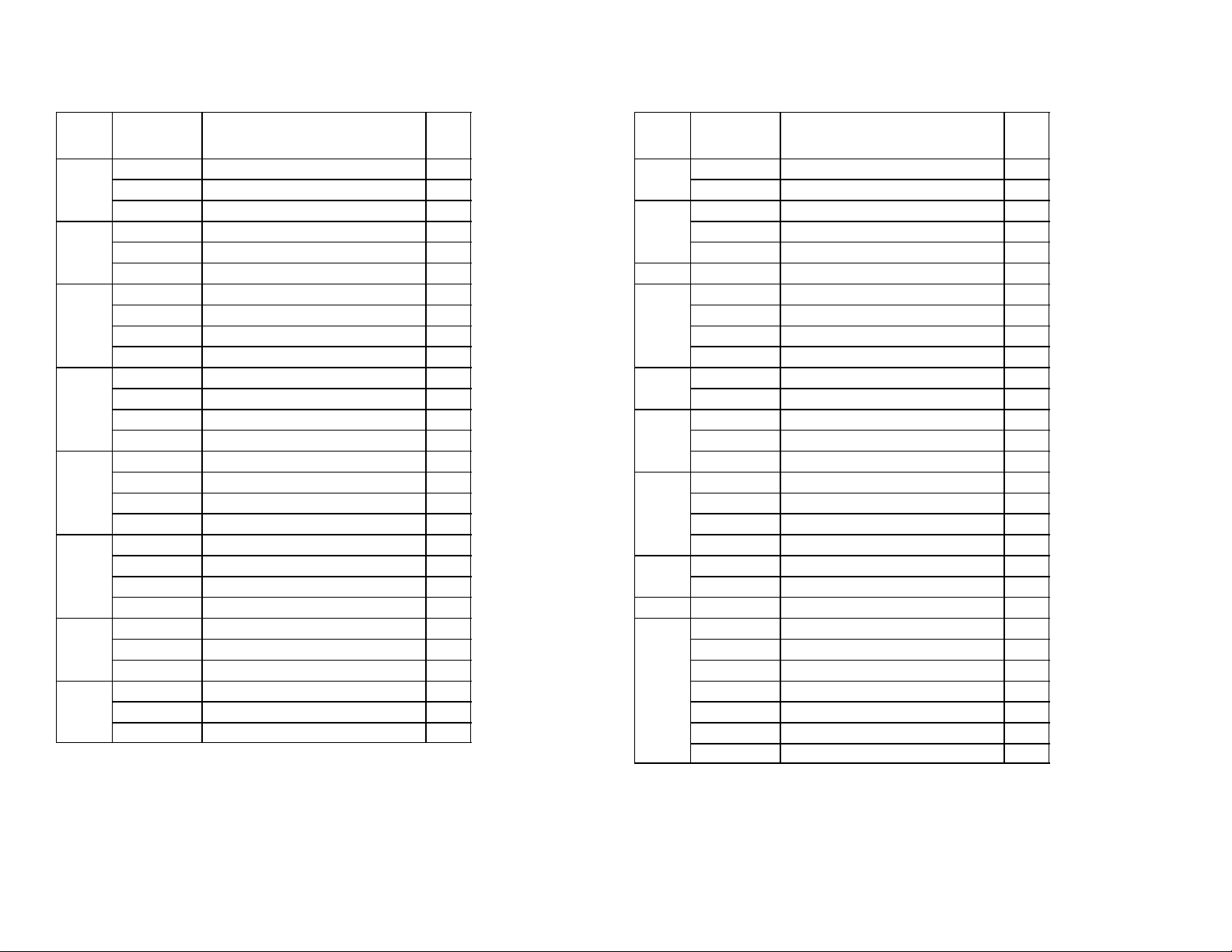
CONN
NBR Part No. DESCRIPTION QTY.
1
770409000 3/8 Swivel -///8 Barb Elbow 1
311304000 Gasket 1
309852000 170 Oeitker Clamp 2
2
770695000 1/2 x 3/8 x 3/8 Barb Tee 1
309852000 170 Oeitker Clamp 4
319681000 210 Oeitker Clamp 2
3
176206000 1/2 Swivel Nut 1
176205000 Swivel Barb 1
311304000 Gasket 1
309852000 170 Oeitker Clamp 2
4
770104000 1/4 Swivel Hose Stem 1
176017000 1/4 Swivel Nut 1
111353000 145 Oeitker Clamp 2
178025100 Gasket 1
5
176271000 1/4 x 3/8 Swivel Hose Stem 1
19
311242000 3/8 Swivel Nut 1
311304000 Gasket 1
111353000 145 Oeitker Clamp 2
6
770699000 1/2 x 1/2 x 3/8 Barb Tee 2
770423000 1/2 x 3/8 Barb Splice 1
319681000 210 Oeitker Clamp 10
309852000 170 Oeitker Clamp 6
7
770407000 3/8 x 1/4 Barb Splice 1
309852000 170 Oeitker Clamp 4
111353000 145 Oeitker Clamp 2
8
770607000 3/8 x 3/8 x 1/4 Barb Tee 1
309852000 170 Oeitker Clamp 4
111353000 145 Oeitker Clamp 2
CONN
NBR Part No. DESCRIPTION QTY.
9
770403000 3/8 x 3/8 Barb Splice 1
309852000 170 Oeitker Clamp 4
10
770621000 3/8 x 1/4 x 1/4 Barb Tee 1
309852000 170 Oeitker Clamp 2
111353000 145 Oeitker Clamp 4
11 Installer Supplied 1
12
176025000 3/8 Swivel Hose Barb 1
311242000 3/8 Swivel Nut 1
309852000 170 Oeitker Clamp 2
311304000 Gasket 1
13
274244000 Gas QD Slot 1/4 Barb 1
111353000 145 Oeitker Clamp 2
14
274212000 Syrup QD 1/4 Flare 1
770465000 1/4 Flare x 3/8 Barb 1
309852000 170 Oeitker Clamp 2
15
770699000 1/2 x 1/2 x 3/8 Barb Tee 1
770423000 1/2 x 3/8 Barb Splice 1
309852000 170 Oeitker Clamp 4
319681000 210 Oeitker Clamp 6
16
770402000 1/4 x 1/4 Barb Splice 1
111353000 145 Oeitker Clamp 4
17 Installer Supplied
18
274212000 Syrup QD 1/4 Flare 1
770465000 1/4 FFL x 3/8 Barb 1
309852000 170 Oeitker Clamp 2
311035000 Strainer 1
770750010 1/4 MFL to 1/4 MPT 2
310822000 1/4 FFL to 1/4 FFL 1
178025100 Gasket 2
0713
Page 21
20
1
2
3
4
5
6
7
8
9
10
11
12
13
14
15
16
17
18
partnum
SPRITE
DIET
ORANGE
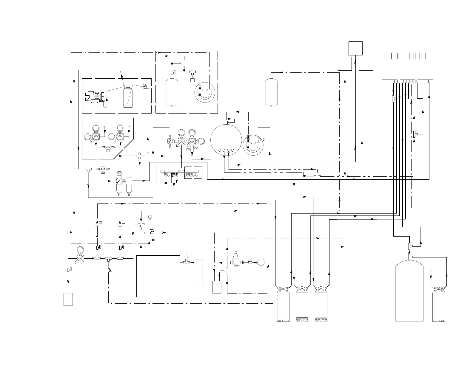
FIGURE 10. CONNECTION DIAGRAM (CENTER–ISLAND INSTALLATION
WITH BULK SYRUP TANK HOOKUP)
SYRUP
BULK
TANK
Page 22
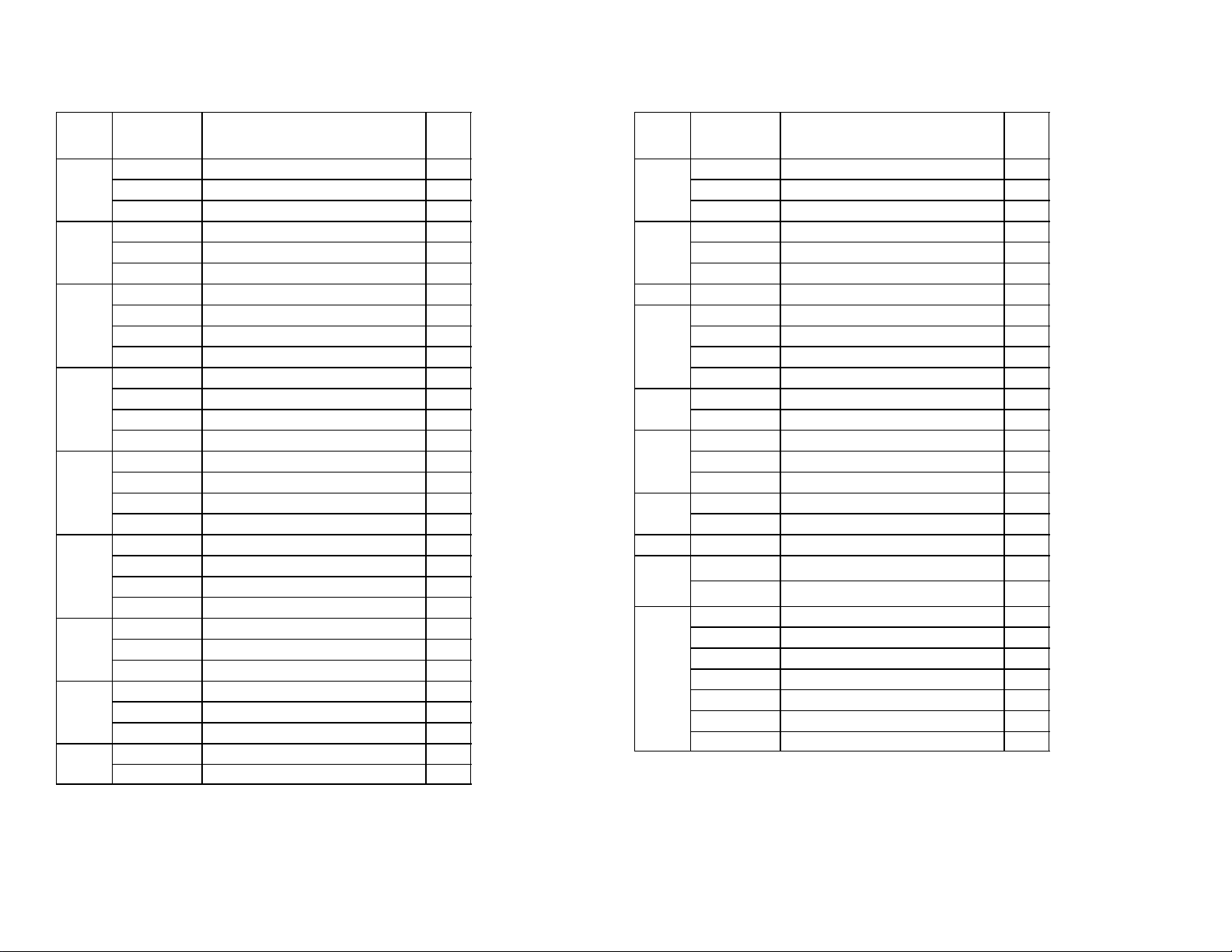
CONN
NBR Part No. DESCRIPTION QTY.
1
770409000 3/8 Swivel -///8 Barb Elbow 1
311304000 Gasket 1
309852000 170 Oeitker Clamp 2
2
770695000 1/2 x 3/8 x 3/8 Barb Tee 1
309852000 170 Oeitker Clamp 4
319681000 210 Oeitker Clamp 2
3
176206000 1/2 Swivel Nut 1
176205000 Swivel Barb 1
311304000 Gasket 1
309852000 170 Oeitker Clamp 2
4
770104000 1/4 Swivel Hose Stem 1
176017000 1/4 Swivel Nut 1
111353000 145 Oeitker Clamp 2
178025100 Gasket 1
5
770304000 1/4 x 3/8 Swivel Hose Stem 1
21
311242000 3/8 Swivel Nut 1
311304000 Gasket 1
111353000 145 Oeitker Clamp 2
6
770699000 1/2 x 1/2 x 3/8 Barb Tee 2
770423000 1/2 x 3/8 Barb Splice 1
319681000 210 Oeitker Clamp 10
309852000 170 Oeitker Clamp 6
7
770407000 3/8 x 1/4 Barb Splice 1
309852000 170 Oeitker Clamp 4
111353000 145 Oeitker Clamp 2
8
770607000 3/8 x 3/8 x 1/4 Barb Tee 1
309852000 170 Oeitker Clamp 4
111353000 145 Oeitker Clamp 2
9
770403000 3/8 x 3/8 Barb Splice 1
309852000 170 Oeitker Clamp 4
CONN
NBR Part No. DESCRIPTION QTY.
10
770621000 3/8 x 1/4 x 1/4 Barb Tee 1
309852000 170 Oeitker Clamp 2
111353000 145 Oeitker Clamp 4
11
770807020 1/2 Flare x 3/8 Barb Adapter 1
309852000 170 Oeitker Clamp 2
178025000 Gasket 1
12 Installer Supplied 1
13
176025000 3/8 Swivel Hose Barb 1
311242000 3/8 Swivel Nut 1
309852000 170 Oeitker Clamp 2
311304000 Gasket 1
14
274244000 Gas QD Slot 1/4 Barb 1
111353000 145 Oeitker Clamp 2
15
274212000 Syrup QD 1/4 Flare 1
770465000 1/4 Flare x 3/8 Barb 1
309852000 170 Oeitker Clamp 2
16
770402000 1/4 x 1/4 Barb Splice 1
111353000 145 Oeitker Clamp 4
17 Installer Supplied
18
770609000 3/8 x 3/8 x 3/8 Barb Tee 1
309852000 170 Oeitker Clamp 6
19
274212000 Syrup QD 1/4 Flare 1
770465000 1/4 FFL x 3/8 Barb 1
309852000 170 Oeitker Clamp 2
311035000 Strainer 1
770750010 1/4 MFL to 1/4 MPT 2
310822000 1/4 FFL to 1/4 FFL 1
178025100 Gasket 2
0713
Page 23
22
10
11
12
13
14
15
16
17
18
19
1
2
3
4
5
6
7
8
9
orange
coke
coke
diet
coke
sprite
partnum
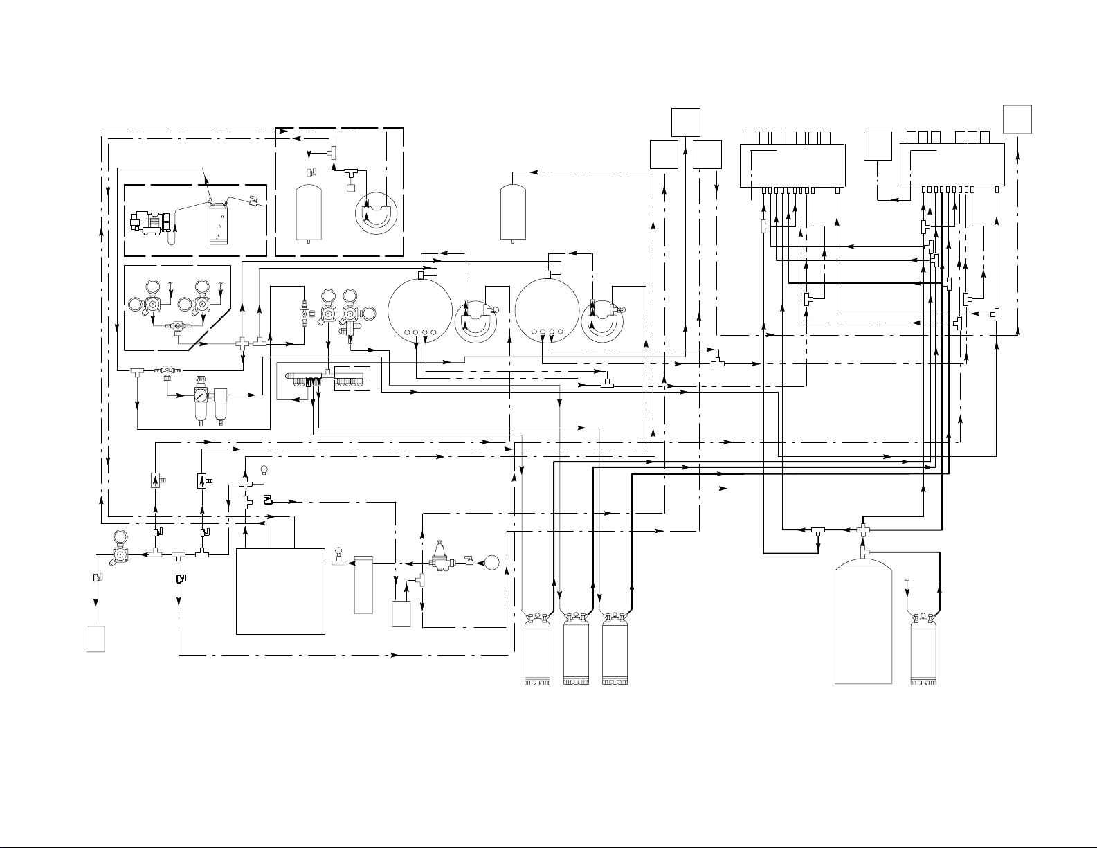
FIGURE 11. CONNECTION DIAGRAM (CENTER–ISLAND AND SECOND DISPENSER
INSTALLATION WITH BULK SYRUP TANK HOOKUP)
Page 24
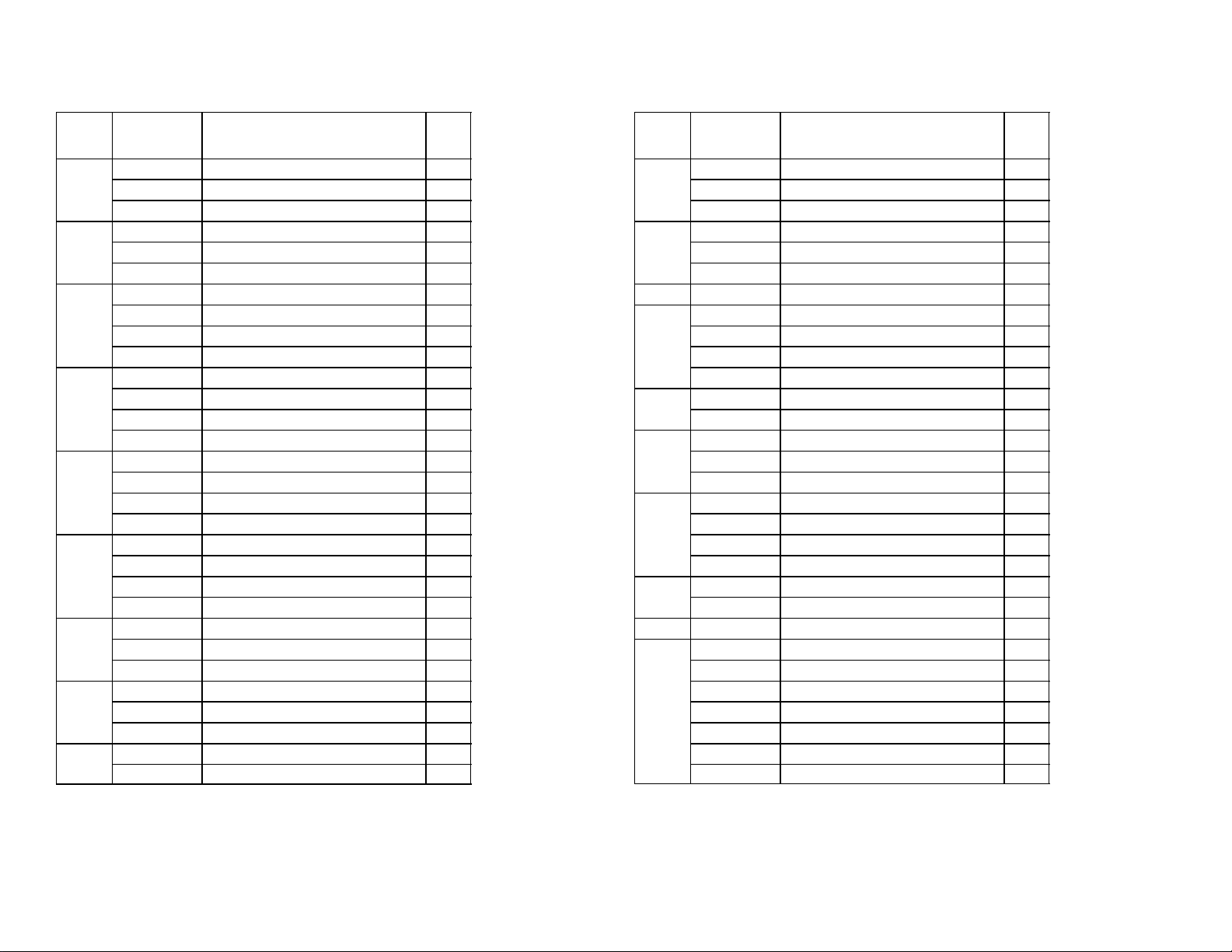
CONN
NBR Part No. DESCRIPTION QTY.
1
770409000 3/8 Swivel -///8 Barb Elbow 1
311304000 Gasket 1
309852000 170 Oeitker Clamp 2
2
770695000 1/2 x 3/8 x 3/8 Barb Tee 1
309852000 170 Oeitker Clamp 4
319681000 210 Oeitker Clamp 2
3
176206000 1/2 Swivel Nut 1
176205000 Swivel Barb 1
311304000 Gasket 1
309852000 170 Oeitker Clamp 2
4
770104000 1/4 Swivel Hose Stem 1
176017000 1/4 Swivel Nut 1
111353000 145 Oeitker Clamp 2
178025100 Gasket 1
5
176271000 1/4 x 3/8 Swivel Hose Stem 1
23
311242000 3/8 Swivel Nut 1
311304000 Gasket 1
111353000 145 Oeitker Clamp 2
6
770699000 1/2 x 1/2 x 3/8 Barb Tee 2
770423000 1/2 x 3/8 Barb Splice 1
319681000 210 Oeitker Clamp 10
309852000 170 Oeitker Clamp 6
7
770407000 3/8 x 1/4 Barb Splice 1
309852000 170 Oeitker Clamp 4
111353000 145 Oeitker Clamp 2
8
770607000 3/8 x 3/8 x 1/4 Barb Tee 1
309852000 170 Oeitker Clamp 4
111353000 145 Oeitker Clamp 2
9
770403000 3/8 x 3/8 Barb Splice 1
309852000 170 Oeitker Clamp 4
CONN
NBR Part No. DESCRIPTION QTY.
10
770621000 3/8 x 1/4 x 1/4 Barb Tee 1
309852000 170 Oeitker Clamp 2
111353000 145 Oeitker Clamp 4
11
770807020 1/2 Flare x 3/8 Barb Adapter 1
309852000 170 Oeitker Clamp 2
178025000 Gasket 1
12 Installer Supplied 1
13
176025000 3/8 Swivel Hose Barb 1
311242000 3/8 Swivel Nut 1
309852000 170 Oeitker Clamp 2
311304000 Gasket 1
14
274244000 Gas QD Slot 1/4 Barb 1
111353000 145 Oeitker Clamp 2
15
274212000 Syrup QD 1/4 Flare 1
770465000 1/4 Flare x 3/8 Barb 1
309852000 170 Oeitker Clamp 2
16
770699000 1/2 x 1/2 x 3/8 Barb Tee 3
770423000 1/2 x 3/8 Barb Splice 1
309852000 170 Oeitker Clamp 8
319681000 210 Oeitker Clamp 14
17
770402000 1/4 x 1/4 Barb Splice 1
111353000 145 Oeitker Clamp 4
18 Installer Supplied
19
274212000 Syrup QD 1/4 Flare 1
770465000 1/4 FFL x 3/8 Barb 1
309852000 170 Oeitker Clamp 2
311035000 Strainer 1
770750010 1/4 MFL to 1/4 MPT 2
310822000 1/4 FFL to 1/4 FFL 1
178025100 Gasket 2
0713
Page 25
SERVICE AND MAINTENANCE
POST–MIX DISPENSER SERVICE AND
MAINTENANCE
Refer to manual provided with the Post–Mix
Dispenser for service and maintenance instructions.
BEVERAGE CONTROL PANEL
ASSEMBLY SERVICE AND
MAINTENANCE
CARBONATOR ASSEMBLY SERVICE AND
MAINTENANCE
WARNING: The carbonator water pump
water inlet strainer screen and liquid
double check valve must be inspected and service at least once a year under normal circumstances, and after any disruptions (plumbing
work, earthquake, etc.) to the water supply system that might cause turbulent (erratic) flow of
water through the system. A carbonator water
pump with no screen or a defective screen in
strainer would allow foreign particles to foul liquid double check valve. CO2 gas could then ba
ck flow into water system and create a health
hazard in the water system
Refer to manual provided with carbonator assembly
for service and maintenance instructions.
ADJUSTING PRIMARY CO2 REGULATORS
CHECKING PLAIN WATER SYSTEM SURGE TANK
AIR, CO2 OR NITROGEN GAS PRESSURE (see
applicable Figure 3, 4, 5, or 6).
NOTE: The plain water surge tank must be
completely drained before proceeding to check
and if necessary, pressurize the tank with the
proper amount of ‘‘commercially dry air, CO2, or
nitrogen gas pressure. Proceed as follows:
1. Unplug carbonator(s) and if applicable, the
optional Water Pressure Booster system power
cords from electrical outlets
2. Close Beverage Control Panel Assembly main
water inlet supply line shutoff valve.
3. Close plain water outlet shutoff valve Post–Mix
Dispenser plain water line is connected to.
4. Disconnect Post–Mix Dispenser plain water line
from shutoff valve.
5. Place bucket under shutoff valve. Open shutoff
valve and allow water to be purged from surge
tank. DO NOT CLOSE VALVE AT THIS TIME.
6. Note: service valve on bottom of the water
system surge tank. The surge tank must be
pressurized to 12 ± 2–PSI (.83 ± .14 Bars) with
commercially dry air, CO2, or nitrogen gas
pressure. Check and make sure surge tank is
properly pressurized.
(see Figure 7).
System Connected to Bulk CO2 Supply
Adjust primary CO2 regulator on bulk CO2 supply tank
to 105–PSI (7.24 Bars)
System Connected to Two–Fifty Pound CO
Cylinders
Adjust two primary CO2 regulators to 105–PSI (7.24
Bars)
ADJUSTING SECONDARY CO
2
2
REGULATORS
Sugar–Base Syrup Tanks CO2 Regulator
Adjust sugar–base syrup tanks CO2 regulator with
100–PSI (6.9 Bars) gauge on secondary CO
regulator assembly to 60–PSI (4.14 Bars).
Diet–Syrup Tank CO
Adjust diet–syrup tank CO2 regulator with 30–PSI
(2.07 Bars) gauge on secondary CO2 regulator
assembly to 12–PSI (.83 Bars).
Regulator.
2
2
7. Close Post–Mix Dispenser plain water outlet
shutoff valve.
8. Open Beverage Control Panel Assembly main
water inlet supply line shutoff valve.
9. Plug the carbonator(s) and if applicable, the
optional Water Pressure Booster system power
cords into electrical outlet.
10. Place bucket under Post–Mix Dispenser plain
water outlet shutoff valve. Open shutoff valve
until a good stream of water flows from valve,
the close valve.
11. Reconnect Post–Mix Dispenser water line to
shutoff valve.
SERVICING OPTIONAL WATER PRESSURE
BOOSTER SYSTEM
(see applicable Figure 3, 4, 5, or 6)
Servicing Water Pump Water Inlet Strainer Screen
1. Unplug carbonator(s) and the Water Pressure
Booster system power cords from electrical
outlets.
24
0713
Page 26
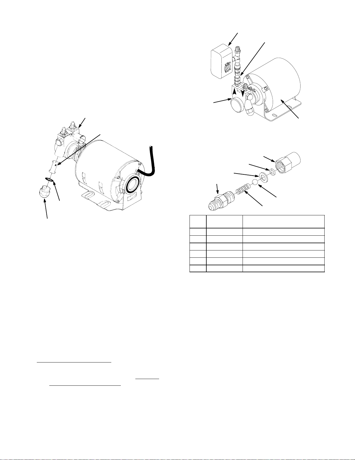
2. Close Beverage Control Panel Assembly water
inlet supply line shutoff valve.
3. Loosen screen retainer, then pull screen retainer
and strainer screen from water pump. (see
Figure 12).
4. Pull strainer screen from screen retainer. Clean
any sediment from screen retainer and pump
screen retainer port.
WATER PUMP
WATER
STRAINER SCREEN
(P/N 315348–000)
PRESSURE
SWITCH
LIQUID CHECK
VALV E
WATER
PUMP
MOTOR
FIGURE 13. WATER PUMP AND MOTOR
1
3
2
6
O–RING
(P/N 315349–000)
SCREEN RETAINER
FIGURE 12. WATER STRAINER SCREEN
5. Inspect strainer screen for holes, restrictions,
corrosion, and other damage. Discard damaged
strainer screen.
6. Check O–Ring on screen retainer. Replace worn
or damaged O–Ring (P/N 315349–000).
NOTE: A strainer screen should always be used,
otherwise particles could foul liquid check valve.
7. Install good or new strainer screen (P/N
315348–000) in screen retainer, then screw
retainer into water pump and tighten securely.
8. Service liquid check valve (refer to next
paragraph, Servicing Liquid Check Valve).
Servicing Liquid Check Valve
1. Service water pump water strainer screen as
instructed in previous paragraph, Servicing
Water In let Strainer Screen; before servicing
liquid check valve.
2. Disconnect pressure switch (see Figure 13) from
liquid check valve assembly outlet, then remove
check valve from water pump outlet. Retain
white tapered gasket inside inlet (female) end of
check valve.
‘
Index
No.
1 317963 Housing
2 312415 Flat Washer, Stainless Steel
3 *312418 Ba;; Seat (quad ring)
4 312419 Ball
5 312196 Spring
6 317965 Retainer
Part
No.
*Install new ball seat at each servicing.
FIGURE 14. LIQUID CHECK VALVE ASSEMBLY
3. Disassemble each check valve as shown in
Figure 14
4. Wipe each part with clean lint–free cloth. Inspect
each part, especially ball for burrs, nicks,
corrosion, deterioration, and other damage.
Discard ball seat and any damaged or suspicious
parts and replace with new parts when
reassembled.
5. Reassemble check valve as shown in Figure 14.
ALWAYS INSTALL NEW BALL SEAT
(QUADDING) P/N 312418–000.
6. Make sure white tapered gasket is in place
inside female end of check valve assembly, then
install check valve assembly on fitting in water
pump outlet port.
7. Connect pressure switch to check valve
assembly outlet.
25
4
5
Name
0713
Page 27

8. Open Beverage Control Panel Assembly water
inlet supply line shutoff valve.
Adjusting Pressure Switch ‘‘CUT OUT’’ (pump stops)
and‘‘CUT IN’’ (pump starts).
9. Plug carbonator(s) and the Water Pressure
Booster system power cords into electrical
outlets.
Checking Water Tank Air, CO2, or Nitrogen Gas
Pressure
NOTE: The Water Pressure Booster system water
tank must be completely drained before
proceeding to check and if necessary, pressurize
the tank with the proper amount of commercially
dry air, CO2, or nitrogen gas pressure. Proceed as
follows:
1. Unplug carbonator(s) and Water Pressure
Booster system power cords from electrical
outlets.
2. Close Beverage Control Panel Assembly water
inlet supply line shutoff valve.
3. Close plain water outlet shutoff valve Post–Mix
Dispenser plain water line is connected to.
4. Disconnect Post–Mix Dispenser plain water line
from shutoff valve.
5. Place bucket under shutoff valve. Open shutoff
valve and allow water to be purged from Water
Pressure Booster System water tank, then close
valve.
NOTE: The Water Pressure Booster system water
tank and the water system surge tank must be
completely drained and make sure they are
properly pressurized with commercially dry air,
CO2, or nitrogen gas pressure before checking
the water pump ‘‘CUT–IN’’ (pump starts) and
‘‘CUT–OUT’’ (pump stops). Proceed as follows:
1. Unplug carbonator(s) and Water Pressure
Booster system power cords from electrical
outlets.
2. Close Beverage Control Panel Assembly water
inlet supply line shutoff valve.
3. Close water manifold plain water shutoff valve
Post–Mix Dispenser plain water line is connected
to. Disconnect water line from shutoff valve.
4. Place bucket under shutoff valve. Open shutoff
valve and allow water to be purged from water
system surge tank and Water Pressure Booster
System water tank. DO NOT CLOSE SHUTOFF
VALVE AT THIS TIME.
5. Note service valve on bottom of Water Pressure
Booster system water tank and water system
surge tank. The Water Pressure Booster system
water tank must be checked to make sure it is
pressurized to 40 ± 5–PSI (2.76 ± .034 Bars)
and the water system surge tank is pressurized
to 12 ± 2–PSI (.83 ± .14 Bars) with commercially
dry air, CO2, or nitrogen gas pressure.
6. Note service valve (see applicable Figure 3, 4, 5,
or 6) on bottom of the Water Pressure Booster
system water tank. The water tank must be
pressurized to 40 5–PSI (2.76 .34 Bars) with
commercially dry air, CO, or nitrogen gas
pressure. Check and make sure water tank is
properly pressurized.
7. Open Beverage Control Panel Assembly water
inlet supply line shutoff valve.
8. Place bucket under Post–Mix Dispenser shutoff
valve. Open valve and allow water to flow until a
good stream of water flows from valve, then
close valve.
9. Reconnect Post–Mix Dispenser plain water line
to shutoff valve.
10. Plug both carbonators and Water Pressure
Booster System power cords into electrical
outlets.
6. Close Post–Mix Dispenser water outlet shutoff
valve, then open Beverage Control Panel
Assembly plain water inlet supply line shutoff
valve.
7. Place bucket under Post–Mix Dispenser water
outlet shutoff valve. Open shutoff valve and allow
water to flow until water surge tank and Water
Pressure Booster System water tank are filled
and a good stream of water flows from shutoff
valve, then close valve.
CAUTION: To avoid damage, do not exceed the
maximum allowable system pressure of 85 ±
5–PSI (5.86 ± .35 Bars).
WARNING: Adjustment nuts are located
close to the high voltage terminals on
the pressure switch. To prevent possible electrical shock, use an insulated 3/8 nut–driver to
make adjustments. Only qualified personnel
should perform adjustments on pressure
switch.
26
0713
Page 28
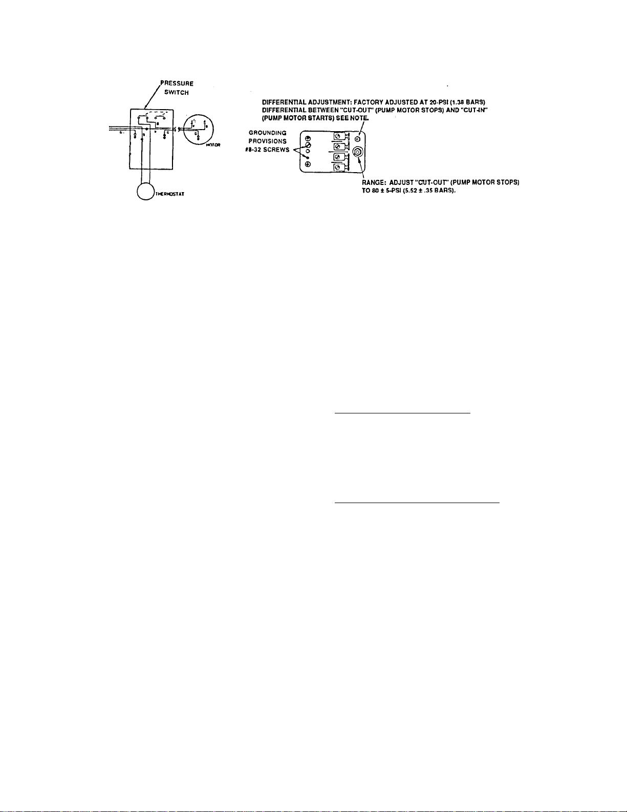
Note: The DIFFERENTIAL adjustment (20–psi) between ‘‘CUT–IN’’ (water pump starts) and ‘‘CUT–OUT’’ (water
pump stops) has been adjusted at the factory and should require no further adjustment. Should differential
adjustment become necessary, turn DIFFERENTIAL ADJUSTMENT nut clockwise to increase differential or turn
nut counterclockwise to decrease differential.
FIGURE 15. PRESSURE SWITCH ADJUSTMENT
8. Using 5/16 nutdriver, remove nut securing
pressure switch cover, then remove cover.
Note: Water pressure gauge to be observed when
checking ‘‘CUT–OUT’’ (water pump stops) is
located just above the water filters. Observing the
water pressure gauge, ‘‘CUT–OUT’’ (water pump
stops) should occur at 85 ± 5–PSI (5.86 ± .35
Bars).
9. Plug Water Pressure Booster System power
cord into electrical outlet.
10. Open Post–Mix Dispenser water outlet shutoff
valve and discharge water into bucket until pump
‘‘CUT– IN’’ (pump starts) occurs, then close
valve. Pump ‘‘CUT–OUT’’ should have occurred
at 85 ± 5–PSI (5.86 ±.35 Bars). If pump
‘‘CUT–OUT’’ was not correct, refer to Figure 15
and turn ‘‘CUT–OUT’’ adjustment nut to the right
(clockwise) for higher pressure or to the left
(counterclockwise) for lower pressure.
11. Repeat step 10) preceding and adjust until
proper pump ‘‘CUT–OUT’’ occurs.
SERVICING OPTIONAL AIR COMPRESSOR
ASSEMBLY AND AIR SYSTEM
MAINTENANCE
Air Compressor Maintenance.
Air compressor assembly air filter must be cleaned or
replaced with replacement air filter (P/N 111421–000)
every 30 to 60 days or more often, depending upon
environmental conditions.
Purging Air Reservoir Tank (Weekly)
IMPORTANT: To prevent water (condensation)
from entering system, water must be purged from
air reservoir tank once a week.
1. Hold appropriate container under bleeder valve
on air reservoir tank (see Figure 7).
2. Open valve to allow water (condensation) to be
purged from reservoir tank and until only air
comes out of valve, then close valve.
12. Install pressure switch cover and secure with
nut.
13. Re–connect Post–Mix Dispenser plain water line
to Water manifold water shutoff valve.
14. Plug carbonator(s) power cord(s) into electrical
outlet.
‘
CLEANING OPTIONAL SYRUP LINES
STRAINERS (SEE FIGURE 15).
NOTE: Use ONLY LUKEWARM WATER. Hot water
destroys the chlorine power of the sanitizer and
cold water does not allow the sanitizer to
dissolve. Lukewarm is warm but not HOT,
approximately body temperature.
27
0713
Page 29
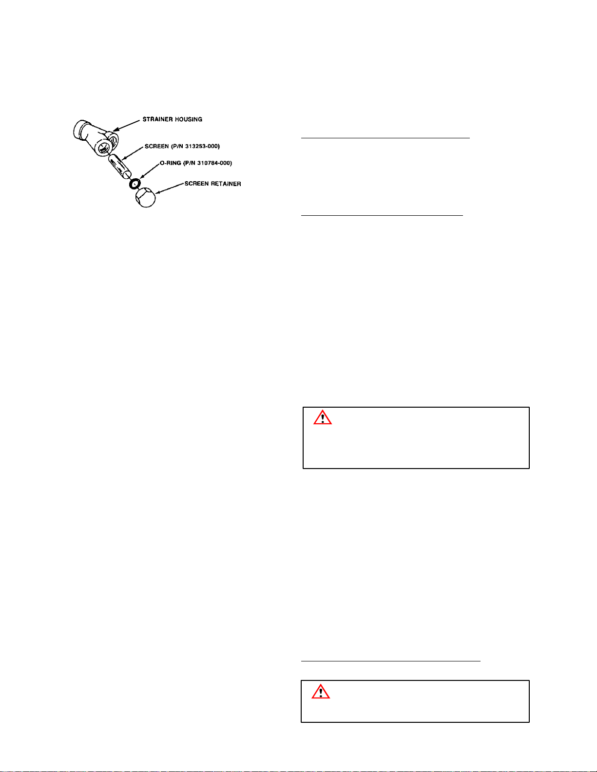
FIGURE 16. SYRUP LINE STRAIANER
1. Using chlor–tergent (Oakite Products, Inc.) or
equivalent sanitizer and LUKEWARM water, mix
2–1/2 gallons (9.46 liters) of sanitizing solution in
a bucket.
2. Disconnect syrup out quick disconnects,
containing the syrup strainers, from all syrup
tanks.
3. Activate all dispensing valves on Dispensers to
relieve pressure from all syrup systems.
4. Loosen syrup strainer screen (see Figure 3–5)
retainer, then pull syrup strainer and screen from
syrup strainer housing.
5. Pull screen from screen retainer. Inspect screen
for holes, restrictions, corrosion, and any other
damage. Discard damaged screen and replace
with a new one.
6. Place quick disconnect and syrup strainer
housing in bucket containing sanitizing solution.
Thoroughly wash quick disconnect and syrup
strainer housing, screen retainer, and screen in
sanitizing solution.
7. Thoroughly rinse quick disconnect and syrup
strainer housing, screen retainer and screen with
potable water.
8. Install screen in screen retainer, then screw
screen retainer into water strainer housing.
Tighten retainer only finger tight.
11. Connect syrup out quick disconnects to all syrup
tanks.
WATER FILTERS REPLACEMENT
Refer to Water Filtration System manual for water
filters replacement instructions.
SANITIZING SYRUP SYSTEMS
The syrup systems should be sanitized every
90–days using Chlor–Tergent (Oakite Products, Inc.)
or equivalent sanitizer. Refer to manual provided with
the Post–Mix Dispenser for sanitizing instructions.
REPLENISHING CO2 SUPPLY
NOTE: When indicator on CO2 cylinder regulator
assembly 1800–PSI (124.1 Bars) gauge is in
shaded (‘‘Change CO2 Cylinder’’) portion of dial,
CO
cylinder is almost empty and should be
2
changed.
1. Fully close (clockwise) CO2 cylinder valve.
2. Slowly loosen CO2 regulator assembly coupling
nut allowing CO2 pressure to escape, then
remove regulator assembly from empty CO
2
cylinder.
3. Unfasten safety chain and remove empty CO
2
cylinder.
WARNING: To avoid personal injury
and/or property damage, always secure
CO2 cylinder with safety chain to prevent if from
falling over. Should the valve become accidentally damaged or broken off, CO2 cylinder can
cause serious personal injury.
4. Position CO2 cylinder and secure with safety
chain.
5. Make sure gasket is in place inside CO
2
regulator coupling nut, then install regulator on
CO2 cylinder.
6. Open (counterclockwise) CO2 cylinder valve
slightly to allow lines to slowly fill with gas, then
open valve fully to back–seat valve.
(Back–seating valve prevents leakage around
valve shaft).
7. Check CO2 connections for leaks. Tighten loose
connections.
REPLENISHING SYRUP SUPPLY
9. Repeat steps 4) through 8) to clean and sanitize
remaining syrup strainers.
10. Sanitize all syrup systems as instructed.
WARNING: To avoid personal injury or
property damage, do not attempt to remove syrup tank cover until CO2 pressure has
been released from tank.
28
0713
Page 30

1. Remove CO2 disconnect and syrup disconnect
from empty syrup tank, then remove tank.
2. Place full syrup tank in position, then connect
CO
disconnect and syrup disconnect to full
2
syrup tank.
SYRUP FLAVOR CHANGE
Sanitize applicable syrup system as instructed, then
install full tank of new flavor syrup.
‘
29
0713
Page 31
TROUBLESHOOTING
IMPORTANT: Only qualified personnel should service internal components or electrical wiring.
WARNING: If repairs are to be made to carbonated water system, disconnect electrical
power to Cooling Unit, shut off plain water and CO2 supplies, and relieve the carbonated
water system pressure before proceeding. If repairs are to be made to syrup system,
remove quick disconnects from applicable syrup tank, then relieve the system pressure before
proceeding. If repairs are to be made to CO2 system, stop dispensing, shut off CO2 supply, then
relieve the system pressure before proceeding.
If repairs are to be made to an existing Remote Condensing unit, disconnect the power to the
condensing unit before proceeding
TROUBLESHOOTING OPTIONAL WATER PRESSURE BOOSTER SYSTEM
Trouble Probable Cause Remedy
WATER PUMP NOT
OPERATING
WATER PUMP
‘‘SHORTCYCLES’’
A. Power cord unplugged from
electrical outlet.
B. Electrical circuit fuse blown or
circuit breaker tripped.
C. Water pump motor inoperative C. Have Service Technician replace
D. Water pump pressure switch
inoperative.
E. Thermal overload switch
inoperative.
F. Plain water inlet pressure
above 60–PSI (4.14 Bars).
A. Water tank is overcharged with
air, CO2 or nitrogen gas.
B. Check to see if check valve on
water pump outlet is leaking
water
C. Water tank shutoff valve is
closed
D. Water pump pressure switch is
not correctly adjusted.
A. Plug power cord into electrical
outlet.
B. Replace fuse or reset circuit
breaker.
inoperative moto
D. Have Service Technician replace
inoperative pressure switch.
E. Have Service Technician replace
inoperative thermal overload
switch.
F. Have Service Technician reset
‘‘CUT IN’’ pressure on pressure
switch to 10–PSI (.68 Bars)
above water inlet pressure.
A. Evacuate all water from Beverage
Support System. Adjust pressure
to 40 ± 5–PSI (2.76 ± .34 Bars),
then reactivate system.
B. Disassemble and clean check
valve. If valve is damaged,
replace.
C. Open water tank shutoff valve
D. Have Service Technician readjust
the pump pressure switch.
WATER PUMP ‘‘LONG
CYCLES’’
A. Water tank is undercharged
with air, CO2, or nitrogen gas.
B. Water tank gas bladder is
leaking.
30 0713
A. Evacuate all water from Beverage
Support System. Adjust gas
pressure to 40 ± 5 PSI, (2.76 ±
.34 Bars) then reactivate system.
B. Replace water tank, pressurize
gas pressure to 40 ± 5–PSI (2.76
± .34 Bars), then reactivate.
Page 32

Trouble RemedyProbable Cause
WATER PUMP ‘‘LONG
CYCLES’’ (CON’T)
C. Water pump pressure switch is
not correctly adjusted.
D. Water pre–filter is plugged
(this condition will be
accompanied by a change in
pitch of the water pump when
operating.)
E. Water supply is shut off to
Beverage Control Panel (this
condition will be accompanied
by a change in pitch of the
water pump when operating).
F. Water pump failure. F. Have Service Technician replace
G. Water filter activation valve is
in ‘‘OPEN’’ position.
H. Leak in plain water lines
leaving Beverage Control
Panel Assembly.
C. Verify pressure switch
‘‘CUT–OUT’’ pressure is adjusted
at 85 ± 5 PSI (5.86 ±.35 Bars) or
‘‘CUT–IN’’ pressure is adjusted at
60 ± 5 PSI (4.14 ± .35 Bars).
Have Service Technician readjust
pressure switch.
D. If water inlet pressure gauge
reads below 5–PSI (.34 Bars)
while water pump is
operating,replace water pre–filter.
E. Verify plain water inlet shutoff
valve is in ‘‘OPEN’’ position. Verify
all other water shutoff valves on
Beverage Control Panel are in
‘‘OPEN’’ positions.
water pump. Verify water is being
supplied to the pump (starving
water pump of water is primary
reason for pump failure).
G. Place water filter activation valve
in ‘‘CLOSED’’ position.
H. Check for water leak in plain
water lines leading to equipment
connected to Beverage Control
Panel Assembly.
WATER INLET PRESSURE
GAUGE READS TOO LOW
WATER INLET PRESSURE
GAUGE READS TOO HIGH
AIR COMPRESSOR DOES
NOT OPERATE
A. Water inlet shutoff valve is in
‘‘CLOSED’’ position.
B. Water pre–filter is clogged. B. Replace water pre–filter.
C. Water pressure regulator is
incorrectly adjusted.
D. Water pressure regulator
strainer is clogged.
E. Water pressure regulator
inoperative.
A. Water pressure regulator is
incorrectly adjusted.
B. Water pressure regulator
inoperative.
A. Power cord unplugged from
electrical outlet.
B. Power cord power switch in
‘‘OFF’’ position.
C. Electrical circuit fuse blown or
circuit breaker tripped.
D. Air compressor pressure
switch is inoperative.
A. Place water inlet shutoff valve in
‘‘OPEN’’ position.
C. Readjust water pressure regulator
to 75 ± 5 PSI. (5.17 ± .34 Bars)
D. Remove and clean or replace the
water strainer screen.
E. Replace water pressure regulator
and adjust to 75 ± 5 PSI. (5.17 ±
.34 Bars)
A. Readjust water pressure regulator
to 75 ± 5 PSI. (5.17 ± .34 Bars)
B. Replace water pressure regulator
and adjust to 75 ± 5 PSI. (5.17
±.34 Bars)
A. Plug air compressor power cord
into electrical outlet.
B. Place power switch in ‘‘ON’’
position.
C. Replace fuse or reset circuit
breaker.
D. Have Service Technician check
and/or replace pressure switch.
071331
Page 33

Trouble RemedyProbable Cause
AIR COMPRESSOR DOES
NOT OPERATE (CON’T)
AIR COMPRESSOR ‘SHORT
CYCLES’’
DISPENSED DRINKS HAVE
‘OFF’’ TASTE
AIR COMPRESSOR‘‘LONG
CYCLES’’
E. Air/CO2 changeover valve on
CO
panel set to CO
2
position.
2
E. Select desired valve position.
F. Air compressor is inoperative. F. Replace air compressor.
A. Air compressor pressure
switch is not correctly
A. Have Service Technician adjust
pressure switch.
adjusted.
B. Air tank contains water
(condensation).
B. Drain water (condensation) from
air tank by opening condensation
drain tube valve. Close valve after
draining tank. TO PREVENT
WATER (CONDENSATION)
FROM ENTERING SYSTEM,
WATER MUST BE PURGED
FROM AIR TANK ONCE A
WEEK.
A. Air tank contains excessive
water (condensation).
A. Drain water (condensation) from
air tank, then sanitize syrup
systems and replace
contaminated syrup supplies.
A. Condensation drain tube valve
on air tank is in ‘‘OPEN‘’
A. Place condensation drain valve in
‘‘CLOSED’’ position.
position.
B. Pressure relief valve on air
B. Close air tank lid relief valve.
tank lid is open
C. Air compressor air filter is
C. Replace air compressor air filter.
clogged.
D. Air tank lid not properly
D. Properly install lid on air tank.
installed.
E. Leak in air system lines and/or
regulators.
E. Check for leak in air line from air
compressor to air tank. Check line
from air tank to air/CO change
over valve. Check regulator and
lines to syrup tanks. Check line to
shake machine.
F. Air compressor inoperative F. Replace air compressor.
WATER INLET PRESSURE
GAUGE READS TOO LOW
A. Water inlet valve in
‘‘CLOSED’’ position.
A. Place water inlet shutoff valve in
‘‘OPEN’’ position.
B. Water pre–filter is clogged. B. Replace water pre–filter.
C. Water pressure regulator is
incorrectly adjusted.
D. Water pressure regulator
strainer is clogged.Water
pressure regulator strainer is
C. Readjust water pressure regulator
to 75 ± 5 PSI (5.17 ± .34 Bars).
D. Clean or replace water strainer
filter after closing main water
shutoff valve.
clogged.
E. Water pressure regulator
E. Call Service Technician.
inoperative.
WATER INLET PRESSURE
GAUGE READS TOO HIGH
A. Water pressure regulator is
incorrectly adjusted.
B. Water pressure regulator
A. Readjust water pressure regulator
to 75–PSI (5.17 Bars)
B. Call Service Technician.
inoperative.
NOTE: Refer to manual provided with carbonator for troubleshooting information.
32 0713
Page 34
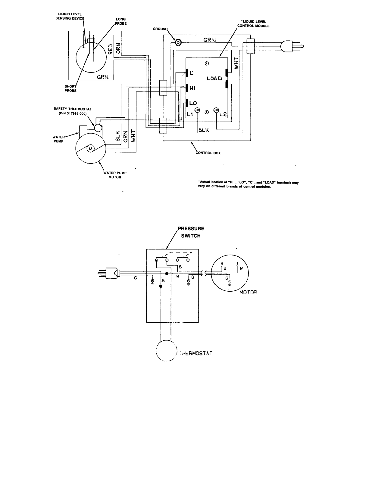
FIGURE 1. WIRING DIAGRAM (CARBONATOR)
FIGURE 2.WIRING DIAGRAM
(OPTIONAL WATER PRESSURE BOOSTER SYSTEM)
071333
Page 35
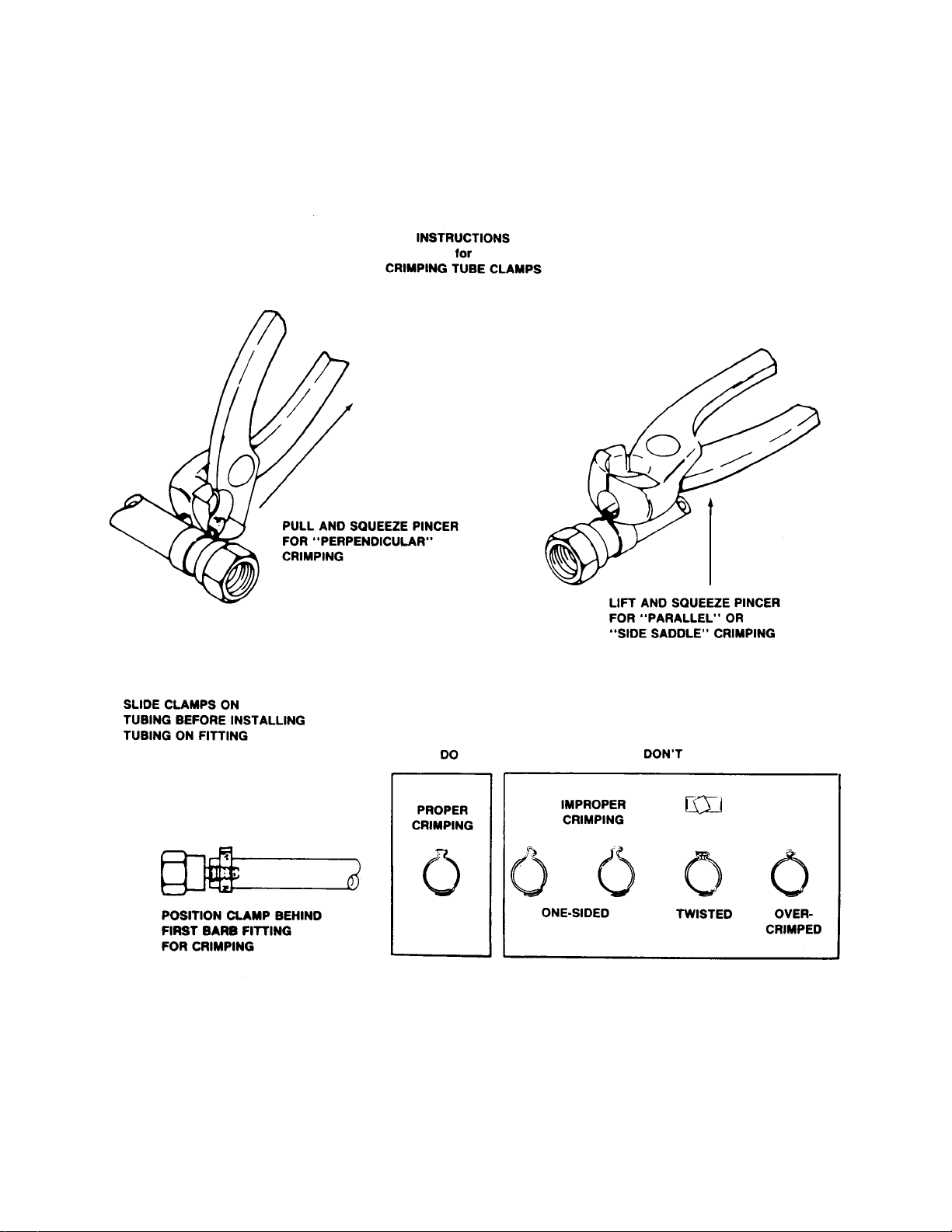
FIGURE 3. INSTRUCTIONS FOR CRIMPING TUBE CLAMPS
34 0713
Page 36
10
27
27
20
11
15
22
15
1
2
24
131313
78
5
23
25
21
12
15
3
9
15
15
26
16
17
19
13
6
13
4
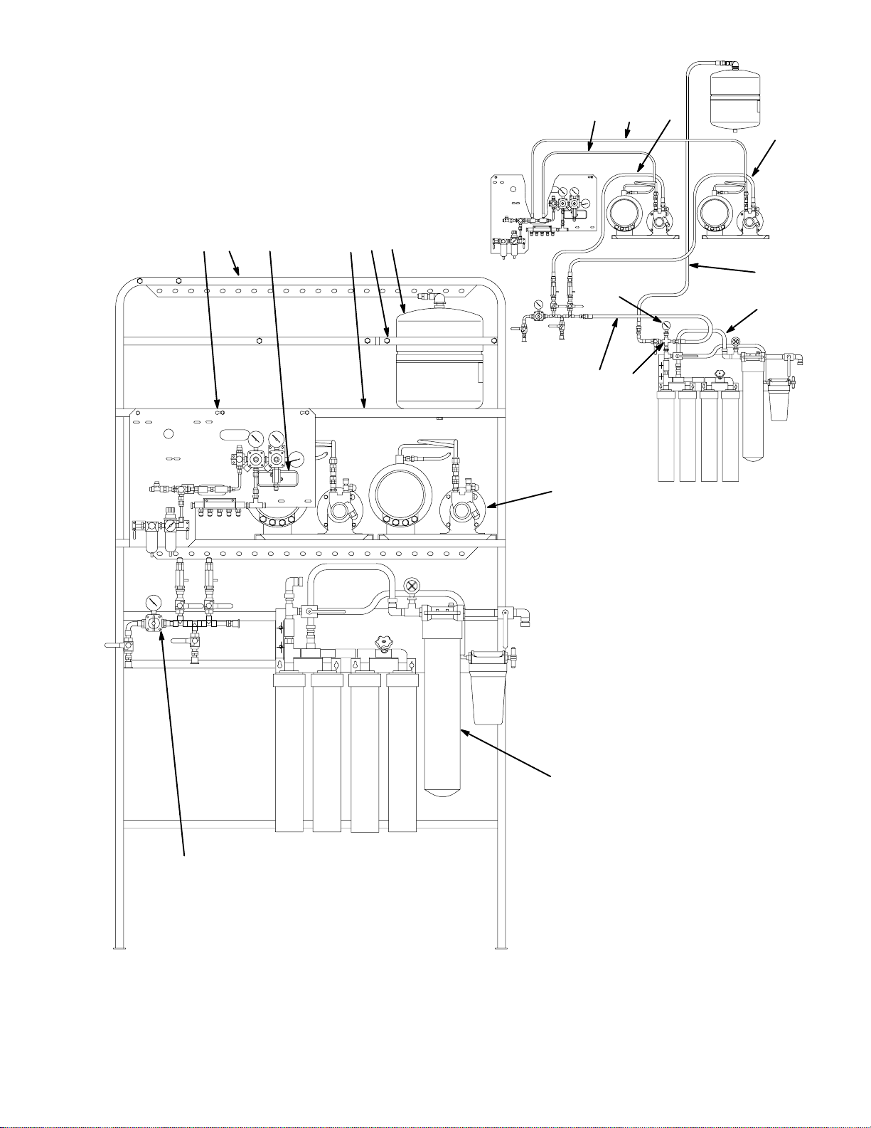
FIGURE 17. BEVERAGE CONTROL PANEL ASS’Y
35
0713
Page 37
BEVERAGE CONTROL PANEL ASS’Y
Item
No. Part No. Name
1416 Beverage Control Panel Ass’y One
Carbonator, Domestic
0516 Beverage Control Panel Ass’y Two
Carbonator, Domestic
1548 Beverage Control Panel Ass’y One
Caronbator, Export
0187 Beverage Control Panel Ass’y Two
Carbonabor, Export
1 0483 CO2 Regulator Ass’y (see Figure 5–2)
2 300911 Frame, Upper
3 416424 Carbonator Ass’y, Domestic (see
Figure 5–9)
496424 Carbonator Ass’y, Export (see Figure
5-9)
4 300914 Manifold Ass’y, Water (see figure 5-10)
5 0657 Platform, Surge Tank
6 0504 Filter System Ass’y Everpure
0928 Filter System Ass’y Cuno
7 300984 Surge Tank, 100 PSI Domestic
8 300893 Strap, Surge Tank Domestic
9 *0875 Self Drilling Screw, Hex Washer HD,
No. 10-16 by 1 1/4” Long
10 0505 Tube Ass’y, .265 I.D. By 30” Long,
From CO2 Regulator Ass’y to Center
Island Carbonator Ass’y
11 315499 Cap, 1-Carbonator
0506 Tube Ass’y, .265 I.D. by 44” Long, from
CO2 Regulator Ass’y to Drive-Thru
Carbonator Ass’y 2-Carbonator
12 0507 Tube Ass’y, .375 I.D. By 21” Long,
from Water Manifold Ass’y to Water
Manifold (2-Carbonator)
13 *320940 Self Drilling Screw Hex Washer HD,
No. 10-16 By 5/8” Long
Item
No. Part No. Name
14 *1300 Washer, .229 I.D. By .049CS
15 311304 Tapered Gasket Black
16 318556 Hanger
17 189429 Hex Nut Keps, 1/4-20 Domestic
*321811 Hex Nut, Keps, No. 10-32 Export
18 165294 Hex Bolt, 1/4-20 By 1” Long
(1-Carbontaor)
19 200469-029 Machine Screw, Phil Pan HD No.
1/4-20 By 1-3/8 Long (Domestic, 2Carbonator)
183040 Machine Screw, Fil Pan HD NO. 10-32
By 7/8” Long, (Export, 2-Carbonator)
20 0508 Tube Ass’y, .375 I.D. By 36” Long
From Water Manifold Ass’y to Center
Island Carbontor Ass’y
21 0193 Water Manifold Ass’y (see Figure 5-11)
22 0705 Tube Ass’y, .375 I.D. By 49” Long,
From Water Manifold Ass’y to
Drive-Thru Carbonator Ass’y
2-Carbonator
23 300912 Tube Ass’y, .375 I.D. By 56” Long,
Surge Tank to Water Manifold Ass’y
Domestic
24 960194 Rubber Channel
25 0143 Gauge, 160 PSI
26 0846 Tube Ass’y, .375 I.D. By 9” Long,
Water Filter Ass’y Everpure
176272-318 Tube Ass’y, .375 I.D. By 18” Long,
Water Filter Ass’y, Cuno
27 178025-100 Tapered Gasket White
28 309812 Tube, Water Inlet, Stainless Steel (not
Shown)
*Zinc Plated Steel Unless Othewise Indicated.
36 0713
Page 38
2
6
7
9
1
7
8
10
6
12
4
4
5
8
10
11
13
7
8
10
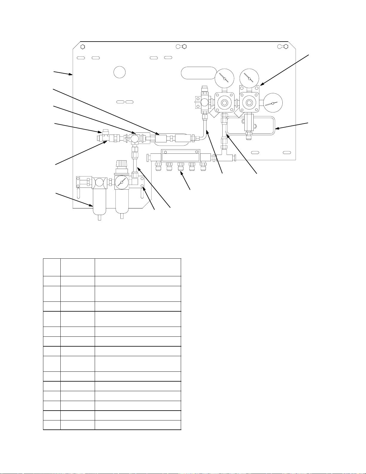
FIGURE 18. CO2 REGULATOR ASS’Y (P/N 0483)
Item
No. Part No. Name
0483 CO2 Regulator Ass’y
1 0137 Manifold Ass’y Carbonataor (see
2 0138 Regulator Ass’y syrup (see Figure 5-5)
3 0145 Manifold and Bracket Ass’y CO2 (see
4 178025-100 Tapered Gasket, White
5 311732 Connector, Swivel, 7/16-20
6 315499 Cap, 7/16
7 398022-400 Machine Screw, SL RD HD Stainless
8 *398024-603 Hex Nut, NO 10-24
9 1375 Panel Mounting
10 331400 Washer .203 I.D. By .024
11 960194 Edging
12 1665 Carbonator manifold ass’y
13 1668 Air Filter Ass’y
Figure 5-3)
Figure 5-8)
Steel, No. 10-24 By 5/8” Long
*Zinc Plated Steel Unless Otherwise Indicated.
3
6
7
8
10
4
5
37
0713
Page 39
91011 3
8
234 5
7
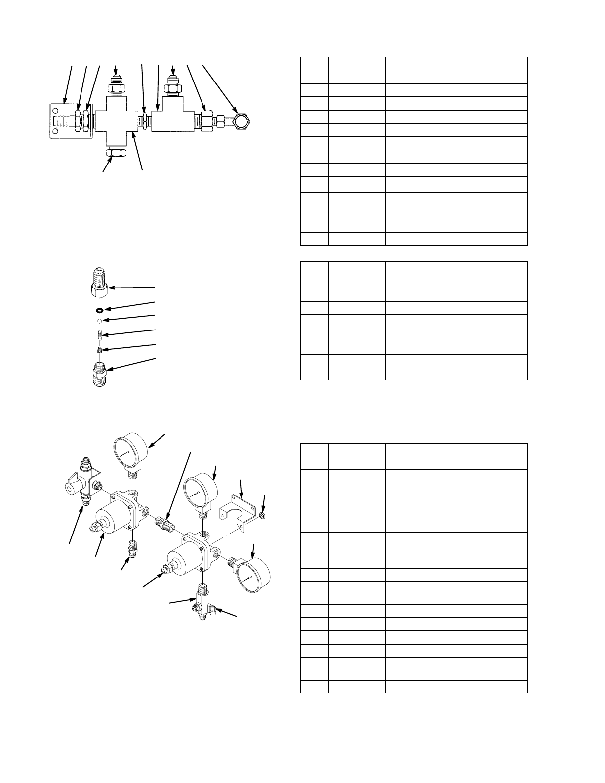
FIGURE 19. CARBONATOR MANIFOLD ASS’Y (P/N 0137)
1
6
5
4
3
2
6
1
Item
No.
Part No. Name
0137 Manifoled Ass’y Carbonstor
1 320640 Fitting 1/4 NPT By 7/16-20
2 183060 Fitting, Tee 1/4 NPT
3 183301-100 Check Valve Ass’y (see figure 5-4)
4 183047 Fitting 1/4 NPT
5 176065 Fitting, Swivel Elbow, 7/16-20
6 178025-100 Tapered Gasket, White
7 183046 Fitting, Cross, 1/4 NPT
8 130066 Fitting, Plug, 1/4-NPT
9 77075001 Fitting, 7/16-20 By 1/4-NPT
10 77080801 Fitting, 3/8-Barb by 7/16-20
11 0656 Bracket, Regulator
Item
No. Part No. Name
183301-100 Check Valve Ass’y
1 183300-001 Manifold, 1 Port
2 183295-100 Body
3 183298 Retainer, Spring
4 183296 Ball
5 183297 Spring
6 183294 Quad Ring, .145 I.D. By .070CS
FIGURE 20. CO2 CHECK VALVE ASS’Y (P/N 183301-001)
3
6
5
8
12
9
1
2
11
4
7
10
13
Item
No. Part No. Name
0138 Regulator Ass’y Syrup
1 311904 Change Over Valve
2 183412 Regulator Ass’y, 100-PSI (see figure
5-6)
3 183286 Gauge, 100 PSI
4 183446 Regulator Ass’y, 30-PSI (see Figure
5-6)
5 183288 Gauge, 30-PSI
6 183047 Fitting, 1/4 NPT
7 183302-100 Check Valve and Manifold Ass’y (see
Figure 5-7)
8 183317 Bracket, Regulator
9 321811 Hex Nut, Keps, NO 10-32
10 183285 Gaugge, 160-PSI
11 183301-100 Check Valve Ass’y (see Figure 5-4)
12 183040 Machine Screw, SL Pan HD No. 10-32
By 2-1/4” Long
13 315499 Cap
FIGURE 21. SYRUP REGULATOR ASS’Y (P/N 0138)
38 0713
Page 40
1
10
15
11
8
16
9
2
3
12
13
14
4
5
7
6
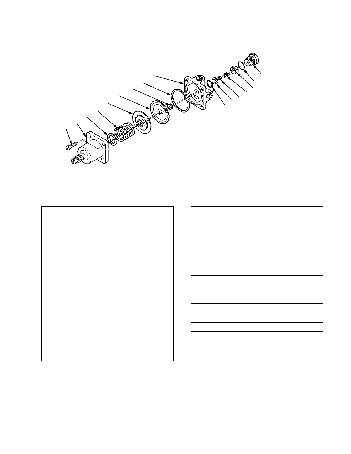
FIGURE 22. CO2 REGULATOR ASS’Y
Item
No. Part No. Name
183412 Regulator Ass’y, 100 PSI
183446 Regulator Ass’y, 30 PSI
183586 Regulator Ass’y 160 PSI
1 183001-007 Body (30 PSI and 100 PSI)
183265 Body (160 PSI)
2 183233 Cover Kit (Includes, Non-Removable
Adjusting Screw)
3 *120081 Machine Screw, Phil Fil HD NO. 10-32
By 1/2” Long
183040 Machine Screw, Phil Fil HD, No. 10-32
By 7/8” Long
4 183009-007 Retainer Seat
5 183008 O-Ring, .489 I.D. By .070 CS
6 183006 Spring, Poppet
7 183007-000 Filter Sleeve
8 130147 Diaphram Assembly
Item
No. Part No. Name
9 183021 Spring Retainer
10 183010 Gasket, Baffle
11 183011-007 Baffle
12 183003 Gasket, Seat
13 130168 Reducing Valve Seat (30 PSI and 100
PSI)
183002 Reducing Valve Seat (160 PSI)
14 130170 Poppet Ass’y (30 PSI and 100 PSI)
183063 Poppet Ass’y (160 PSI)
15 130167 Guide (30 PSI and 100 PSI)
183012 Guide (160 PSI)
16 183020 Adjusting Spring, Sliver, 100 PSI
183064 Adjusting Spring, Bronze, 160 PSI
315424 Adjusting Spring, Blue, 30 PSI
*Zinc Plated Steel Unless Otherwise Indicated.
39
0713
Page 41
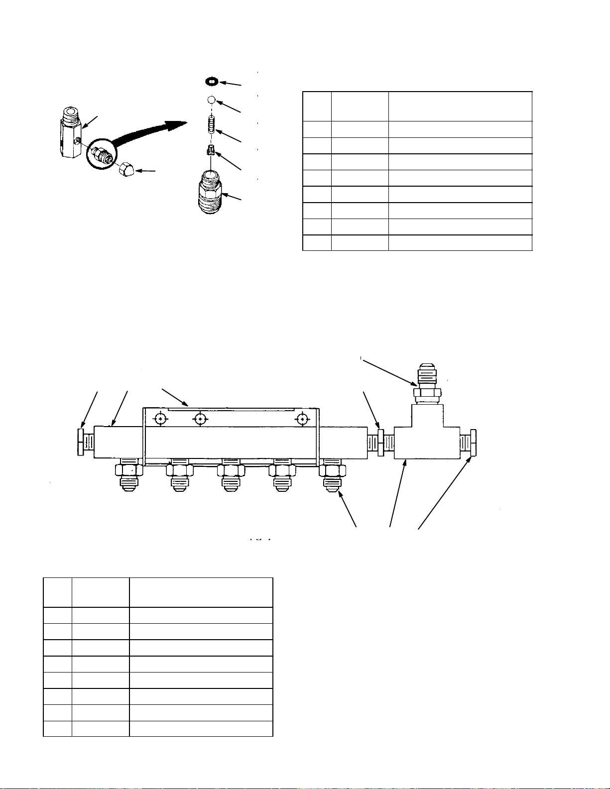
6
Item
1
7
4
5
3
2
No. Part No. Name
183302-100 Check Valve Ass’y
1 183300-003 Manifold, 3 Port
2 183295-100 Body
3 183298 Retainer, Spring
4 183296 Ball
5 183297 Spring
6 183294 Quad Ring, .145 I.D. By .070 CS
7 315499 Cap
FIGURE 23. CHECK VALVE AND MANIFOLD ASS’Y (P/N 183302-100)
7
12
Item
No. Part No. Name
0145 CO2 Manifold and Bracket Ass’y
1 314886 Manifold
2 314887-044 Bracket, Manifold
3 183047 Fitting, 1/4 NPT
4 130066 Fitting, Plug
5 183301-100 Check Valve Ass’y (see Figure 5-4)
6 183060 Fitting Tee
7 770750-010 Fitting, 1/4 NPT By 7/16-20
FIGURE 24. MANIFOLD AND BRACKET ASS’Y (P/N 0145)
34
5
6
4
40 0713
Page 42
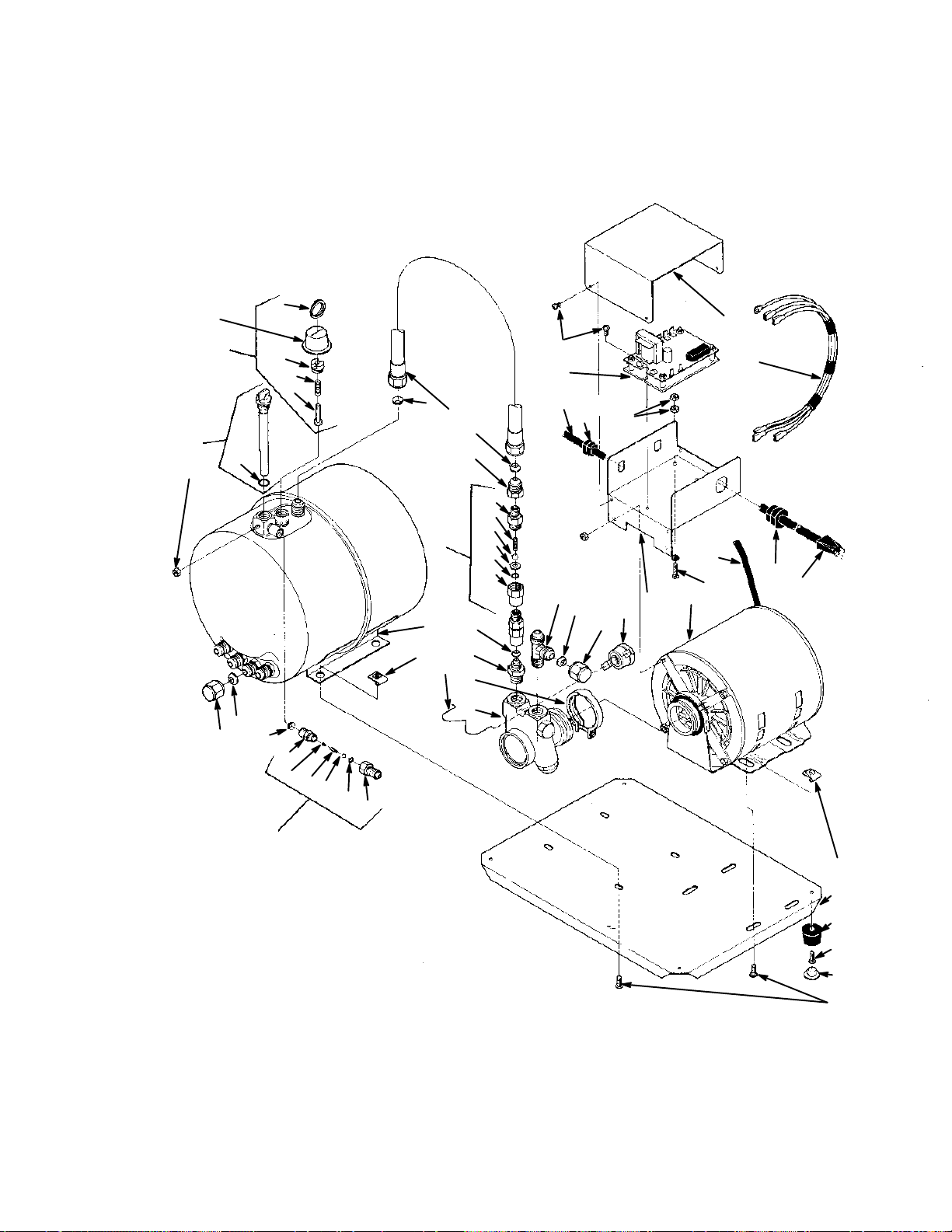
32
34
20
26
38
33
13
39
35
36
37
1
11
46
45
44
43
42
41
29
1
47
2
1
3
5
6
7
4
15
8
9
10
11
12
17
18
19
14
21
23
52
22
26
23
28
16
1
13
27
31
24
25
40
FIGURE 25. LARGE RESERVE CARBONATOR
41
29
51
50
49
48
30
0713
Page 43
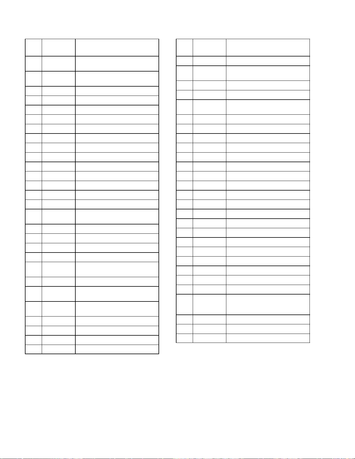
LARGE RESERVE CARBONATOR
Item
No. Part No. Name
416424 Large Reserve Carbonator Ass’y, Low
Profile, Domestic
496424 Large Reserve Carbonator Ass’y, Low
Profile, Export
1 311304 Tapered Gasket, Black
2 318027 Tube Ass’y. .375 I.D. By 13-in Long
3 770716-020 Fitting, 7/16-20 female by 5/8-18 male
4 311765-001 Check Valve Ass’y (includes 5-10)
5 317965 Retainer
6 312196 Spring
7 312419 Ball
8 312415 Washer, .300 I.D.
9 312418 Quad Ring, .239 I.D.
10 317963 Receptacle
11 178025-100 Tapered Gasket, White
12 311437 Fitting, 7/16-20 by 3/8-NPTF
13 770456 Cap Nut, 5/8-18
14 313001 Tee, 3/8 NPT by 5/8-18 by 5/8-18
Branch
15 318039 Clip, Thermostat
16 317989 Thermostat Control
17 187483 Clamp, Pump to Motor
18 312996 Pump, Water, 90-GPH
19 *320271 Thread Rolling, Screw, Phil Pan Hd,
No. 6-32 by 3/8-in.
20 319438 Cover, Control Box
21 314015 Liquid Level Control, 120 VAC 60 HZ,
Domestic
197359 Liquid Level Control 230 VAC 50 HZ
(Export)
22 395098 Strain Relief
23 309947 Cord Motor to Control Box
24 342134 Strain Relief
25 317277 Service Cord
Item
No. Part No. Name
26 *200498-003 Hex Nut Keps, No. 8-32
27 *312578 Machine Screw, SI Rd Hd, No. 8-32 by
3/4-in long
28 319439 Control Box
29 311855 Speed Nut, J-type, 1/4-20
30 *318976 Machine Screw, SI Hex Washer Hd,
1/4-20 by 1/2-in long
31 315183 Motor, 115 VAC, 60 HZ (Domestic)
199020 Motor, 230VAC 50HZ (Export)
32 317974 Water Reflector
33 318362-555 Relief Valve Ass’y (includes 35-38)
34 180343 Ring
35 318361 Bushing, Retaining
36 183249-032 Spring, Red
37 180352 Stem
38 318834-005 Probe, Level Control (includes 40)
39 180024 O-Ring, .424 I.D. by .103 C.S.
40 183310 Check Valve Ass’y (includes 42-47)
41 183309 Adapter
42 183294 Quad Ring, .145 I.D. by .070 C.S.
43 183296 Ball
44 183297 Spring
45 183298 Retainer, Spring
46 183295-100 Body
47 319436-900 Tank
48 330897 Button Plug
49 188087 Thread Cutting Screw, Phil Truss Hd,
Chrome-pltd Steel, No. 10-24 by
1/2-in long.
50 188950 Foot
51 319444-011 Base
52 319921 Wire Harness
*Zinc Plated Steel unless Otherwise indicated
42 0713
Page 44
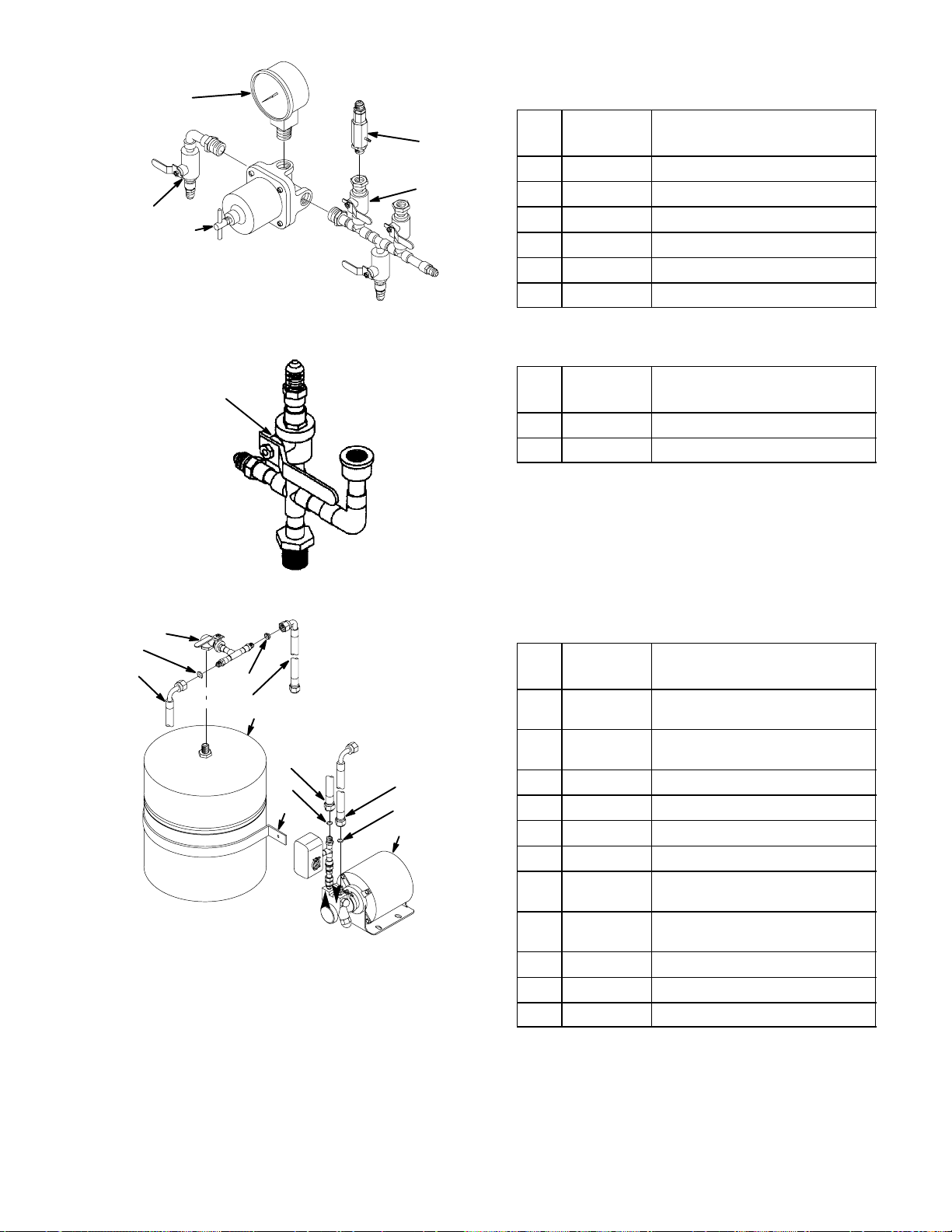
3
Item
5
4
1
2
No. Part No. Name
300914 Water Manifold Ass’y
1 0191 Manifold Ass’y with Shut-Off Valve
2 300922 Water Pressure Regulator
3 301102 Gauge, 100 PSI
4 0190 Manifold Ass’y with Shut-Off Valve
5 0881 Check Valve, Double Vented
FIGURE 26. WATER MANIFOLD ASS’Y (P/N 300914-000)
1
No. Part No. Name
0193 Water Manifold Ass’y
1 300882 Shut-Off ValveShut-Off Valve
FIGURE 27. WATER OUTLET VALVE ASS’Y (P/N 0193)
Item
2
6
4
6
7
1
4
6
3
8
6
5
Item
No. Part No. Name
300915 Water Pressure Booster Kit Ass’y,
Domestic
0515 Water Pressure Booster Kit Ass’y,
Export
1 300984 Water Tank, 100 PSI
2 0200 Shut-Off Valve Assembly
3 300893 Strap, Surge Tank
4 300890 Tube Assembly, .375 I.D. By 14” Long
5 0401 Pump and Motor Assembly, Domesitc
(see Figure 5-13)
0514 Pump and Motor Ass’y Export (see
Figure 5-13)
6 311304 Tapered Gasket, Black
7 0782 Tube Assembly, .375 I.D. By 58” Long
8 1588 Tube Ass’y, .375 I.D. By 74” Long
FIGURE 28. OPTIONAL WATER PRESSURE BOOSTER KIT
43
0713
Page 45
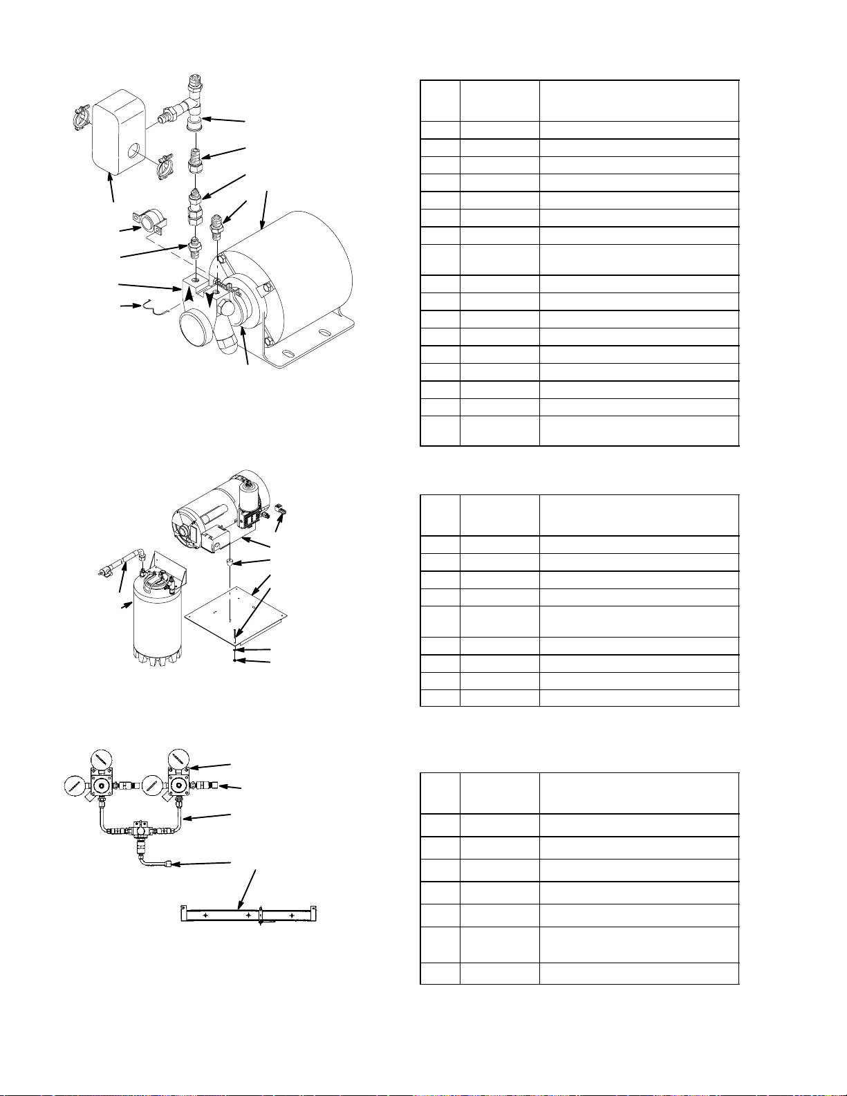
10
Item
No. Part No. Name
12
14
2
7
1
6
3
2
8
4
9
5
1 315183 Motor, 115V. 60 HZ, Domestic
320626 Motor, 230V. 50 HZ, Export
2 178025-100 Tapered Gasket, White
3 0629 Thermostat
4 318039 Clip
5 187483 Clamp, Pump to Motor
6 300888 Pressure Switch
7 311764-001 Check Valve Assembly (see Figure
5-14)
8 312996 Pump, 90 GPH
9 311412 Fitting, 3/8 NPT By 5/8-18
10 311437 Fitting , 3/8 NPT By 7/16-20
11 0877 Cord Domestic (not shown)
0633 Cord, Export (not shown)
12 0491 Tube Assembly
13 0630 Cord (not shown)
14 320640 Fitting, 1/4 NPT By 7/16-20
15 188386 Machine Screw, SL Pan HD, NO.
10-32 By 1/2” Long (not shown)
FIGURE 29. PUMP AND MOTOR ASS’Y
Item
No. Part No. Name
3
2
4
8
9
1
5
7
6
1 111417 Air Tank
2 1111418-011 Compressor, Air
3 183068 Elbow Fitting, 1/4 NPT
4 188950 Rubber Feet
5 041602 Machine Screws, SL Fil HD, Stainless
Steel No. 10-24
6 *398024-603 Nut, No. 10-24
7 1300 Washer, Stainless Steel, .229 I.D.
8 0497 Plate Mounting
9 0674 Drain Tube Ass’y
*Zinc Plated Steel Unless Otherwise Indicated.
FIGURE 30. OPTIONAL COMPRESSOR KIT
6
7
5
Item
No. Part No. Name
1
2
34
1 0650 CO2 Regulator Ass’y (see Figure 5-16)
2 178025-100 Tapered Gasket, White
3 183061 Fitting, 1/4 NPT By 7/16-20
4 0671 Bracket, CO2 Cylinder
5 300933 Tube Ass’y, Hi-Pressure
6 398022-040 Machine Screw, SL RD, HD, Stainless
Steel, NO. 10-24 By 5/8” Long
7 398024-603 Hex Nut, NO. 10-24
FIGURE 31. OPTIONAL PRIMARY CO2 REGULATOR ASS’Y KIT (P/N 0708) FOR TWO 50-POUND CO
CYLINDERS
2
44 0713
Page 46
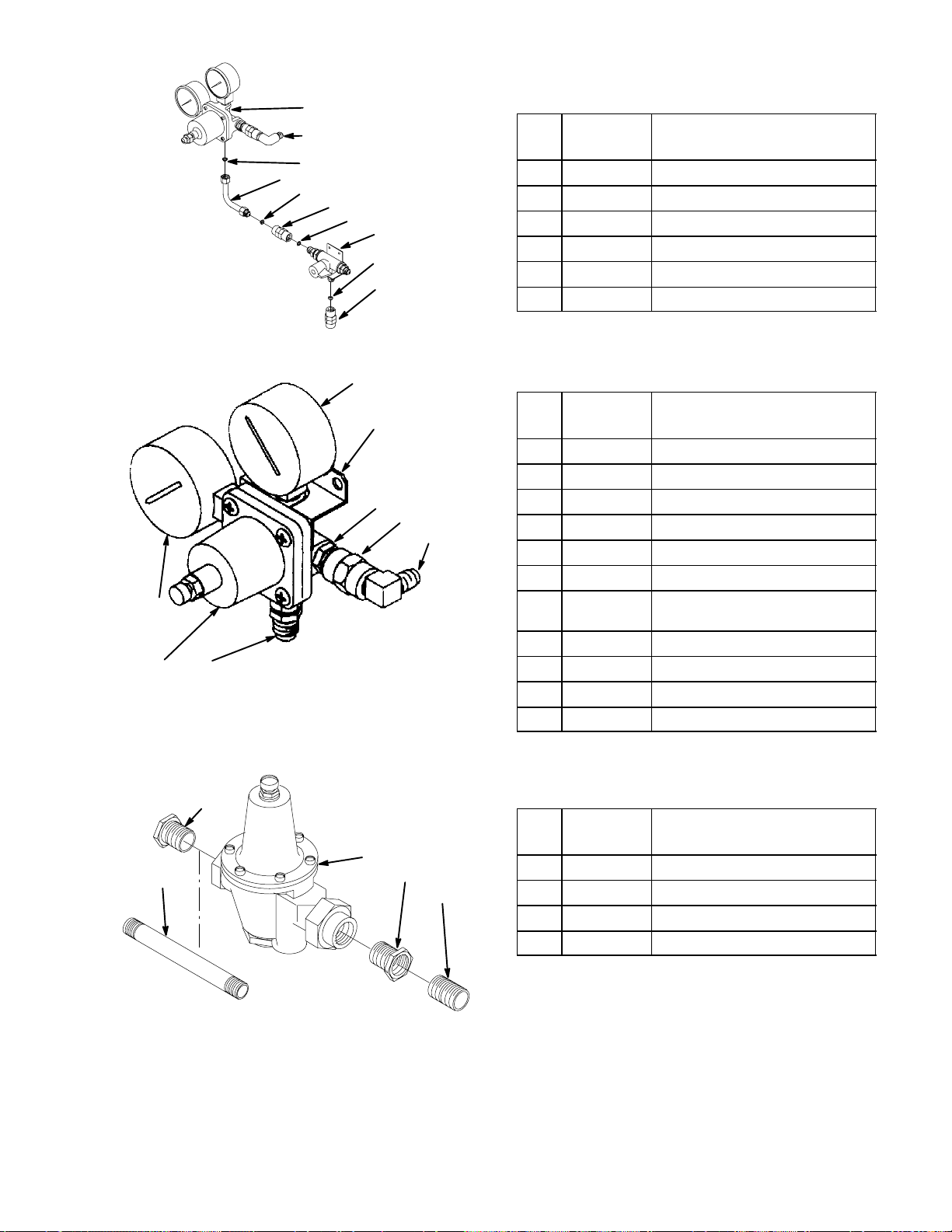
2
6
4
3
4
5
4
1
4
5
Item
No. Part No. Name
1 311904 Changeover Valve
2 0606 Regulator Ass’y (see Figure 5-17)
3 176065 Fitting, Swivel, 7/16-20
4 178025-100 Tapered Gasket, White
5 310822 Fitting, 7/16-20
6 176168-100 Fitting, 1/4 NPT By 7/16-20
*zinc Plated Steel Unless Otherwise Indicated.
FIGURE 32. REGULATOR ASS’Y, HI-PRESSURE (P/N 0650)
2
Item
6
7
8
5
9
11
10
3
1
4
No. Part No. Name
1 183586 Regulator ass’y (see Figure 5-6)
2 183285 Gauge, 160 PSI
3 183267 Gauge, 1800 PSI
4 183061 Fitting, 1/4 NPT By 7/16-20
5 183334 Fitting 1/4 NPT By 7/16-20
6 183317 Bracket, Regulator
7 *183040 Machine Screw, Phil Fil HD, No. 10-32
By 7/8” Long
8 *321811 Hex Nut, NO. 10-32
9 176168-100 Fitting 1/4 NPT By 7/16-20
10 187485 Fitting, 1/4 NPT By 7/16-20
11 178025-100 Tapered Gasket, White
*Zinc Plated Steel Unless Otherwise Indicated.
FIGURE 33. REGULATOR ASS’Y (P/N 0606)
2
Item
No. Part No. Name
1
4
2
3
1 317928 Regulator
2 0711 Fitting
3 0712 Fitting
4 1301 Fitting, 1/2 NPT
FIGURE 34. OPTIONAL WATER PRESSURE REGULATOR KIT (P/N 300919-000)
45
0713
Page 47

WARRANTY
IMI Cornelius Inc. warrants that all equipment and parts are free from defects in material and workmanship under normal use and service. For a copy of the warranty applicable to your Cornelius, Remcor or
Wilshire product, in your country, please write, fax or telephone the IMI Cornelius office nearest you.
Please provide the equipment model number, serial number and the date of purchase.
IMI Cornelius Offices
AUSTRALIA D P.O. 210, D RIVERWOOD, D NSW 2210, AUSTRALIA D (61) 2 533 3122 D FAX (61) 2 534 2166
D AM LANGEN FELDE 32 D A-1222 D VIENNA, AUSTRIA D (43) 1 233 520 D FAX (43) 1-2335-2930
AUSTRIA
D BOSKAPELLEI 122 D B-2930 BRAASCHAAT, BELGIUM D (32) 3 664 0552 D FAX (32) 3 665 2307
BELGIUM
D RUA ITAOCARA 97 D TOMAS COELHO D RIO DE JANEIRO, BRAZIL D (55) 21 591 7150 D FAX (55) 21 593 1829
BRAZIL
ENGLAND
D TYTHING ROAD ALCESTER D WARWICKSHIRE, B49 6 EU, ENGLAND D (44) 789 763 101 D FAX (44) 789 763 644
D 71 ROUTE DE ST. DENIS D F-95170 DEUIL LA BARRE D PARIS, FRANCE D (33) 1 34 28 6200 D FAX (33) 1 34 28 6201
FRANCE
GERMANY
GREECE
HONG
ITALY
NEW
SINGAPORE
SPAIN
USA
D CARL LEVERKUS STRASSE 15 D D-4018 LANGENFELD, GERMANY D (49) 2173 7930 D FAX (49) 2173 77 438
D 488 MESSOGION AVENUE D AGIA PARASKEVI D 153 42 D ATHENS, GREECE D (30) 1 600 1073 D FAX (30) 1 601 2491
KONG D 1104 TAIKOTSUI CENTRE D 11-15 KOK CHEUNG ST D TAIKOKTSUE, HONG KONG D (852) 789 9882 D FAX (852) 391 6222
D VIA PELLIZZARI 11 D 1-20059 D VIMARCATE, ITALY D (39) 39 608 0817 D FAX (39) 39 608 0814
ZEALAND D 20 LANSFORD CRES. D P.O. BOX 19-044 AVONDALE D AUCKLAND 7, NEW ZEALAND D (64) 9 8200 357 D FAX (64) 9 8200 361
D 16 TUAS STREET D SINGAPORE 2263 D (65) 862 5542 D FAX (65) 862 5604
D POLIGONO INDUSTRAIL D RIERA DEL FONOLLAR D E-08830 SANT BOI DE LLOBREGAT D BARCELONA, SPAIN D (34) 3 640 2839 D FAX (34) 3 654 3379
D ONE CORNELIUS PLACE D ANOKA, MINNESOTA D (612) 421-6120 D FAX (612) 422-3255
LD004
4/21/98
 Loading...