

Page 1
Owner’s Manual
LIQUID
CIRCULATORS
MODELS CFF–330 & 500
Part No. 90538
revision B
THIS DOCUMENT CONTAINS IMPORTANT INFORMATION
This Manual must be read and understood before installing or operating this equipment
REMCOR INC: date
PRINTED IN U.S.A
Page 2

TABLE OF CONTENTS
GENERAL INFORMATION 1. . . . . . . . . . . . . . . . . . . . . . . . . . . . . . . . . . . . . . . . . . . . . . . . . . . . . .
DESCRIPTION 1. . . . . . . . . . . . . . . . . . . . . . . . . . . . . . . . . . . . . . . . . . . . . . . . . . . . . . . . . . . .
INSTALLATION 2. . . . . . . . . . . . . . . . . . . . . . . . . . . . . . . . . . . . . . . . . . . . . . . . . . . . . . . . . . . . . . . .
FRONT PANEL REMOVAL 2. . . . . . . . . . . . . . . . . . . . . . . . . . . . . . . . . . . . . . . . . . . . . . . . . .
LOCATION 2. . . . . . . . . . . . . . . . . . . . . . . . . . . . . . . . . . . . . . . . . . . . . . . . . . . . . . . . . . .
LIQUID CONNECTIONS 2. . . . . . . . . . . . . . . . . . . . . . . . . . . . . . . . . . . . . . . . . . . . . . .
ELECTRICAL CONNECTIONS 3. . . . . . . . . . . . . . . . . . . . . . . . . . . . . . . . . . . . . . . . . .
START UP 3. . . . . . . . . . . . . . . . . . . . . . . . . . . . . . . . . . . . . . . . . . . . . . . . . . . . . . . . . . . . . . . .
OPERATION 4. . . . . . . . . . . . . . . . . . . . . . . . . . . . . . . . . . . . . . . . . . . . . . . . . . . . . . . . . . . . . .
MAINTENANCE 4. . . . . . . . . . . . . . . . . . . . . . . . . . . . . . . . . . . . . . . . . . . . . . . . . . . . . . . . . . .
TROUBLESHOOTING 6. . . . . . . . . . . . . . . . . . . . . . . . . . . . . . . . . . . . . . . . . . . . . . . . . . . . . . . . . .
UNIT NOT OPERATING. POWER LIGHT OFF 6. . . . . . . . . . . . . . . . . . . . . . . . . . . . . . . .
UNIT DOES NOT PUMP LIQUID. 6. . . . . . . . . . . . . . . . . . . . . . . . . . . . . . . . . . . . . . . . . . . .
UNIT DOES NOT HEAT. 6. . . . . . . . . . . . . . . . . . . . . . . . . . . . . . . . . . . . . . . . . . . . . . . . . . . .
UNIT DOES NOT COOL; COMPRESSOR RUNS. 6. . . . . . . . . . . . . . . . . . . . . . . . . . . . .
COMPRESSOR DOESN’T RUN; BODY COOL 6. . . . . . . . . . . . . . . . . . . . . . . . . . . . . . . .
COMPRESSOR DOESN’T RUN; BODY HOT 6. . . . . . . . . . . . . . . . . . . . . . . . . . . . . . . . .
SYSTEM TEMPERATURE ERRATIC. 6. . . . . . . . . . . . . . . . . . . . . . . . . . . . . . . . . . . . . . . .
CFF PERFORMANCE DATA 9. . . . . . . . . . . . . . . . . . . . . . . . . . . . . . . . . . . . . . . . . . . . . . . . . . . .
PAGE
REMCOR PRODUCTS COMPANY CHILLER WARRANTY 10. . . . . . . . . . . . . . . . . . . . . . . . .
LIST OF FIGURES
FIGURE 1. TYPICAL CLOSED SYSTEM 2. . . . . . . . . . . . . . . . . . . . . . . . . . . . . . . . . . . . .
FIGURE 2. LIQUID CONNECTIONS 3. . . . . . . . . . . . . . . . . . . . . . . . . . . . . . . . . . . . . . . . .
FIGURE 3. MAJOR PUMP COMPONENTS AND THEIR ASSEMBLY 4. . . . . . . . . . . . .
FIGURE 4. CIRCULATOR DIMENSIONS 7. . . . . . . . . . . . . . . . . . . . . . . . . . . . . . . . . . . . .
FIGURE 5. MODEL CFF WIRING DIAGRAM 8. . . . . . . . . . . . . . . . . . . . . . . . . . . . . . . . . .
LIST OF TABLES
TABLE 1. SPECIFICATIONS 1. . . . . . . . . . . . . . . . . . . . . . . . . . . . . . . . . . . . . . . . . . . . . . . .
i 90538
Page 3

GENERAL INFORMATION
CAUTION: Operating the unit without liquid for more than 5 seconds can result in damage
to the pump. Evidence of dry operation will void the warranty. Read the installation and
start-up sections before operating.
DESCRIPTION
The Remcor Model CFF Liquid Circulator is a self–contained unit consisting of a pump, heater, cooling system,
and 2–stage thermostat housed in a rugged cabinet with a baked-on finished. It will operate with any water
system up to a maximum of 30 gallons (113 liters). The CFF is not designed for continuous cooling at water
temperatures above 85°F (29°C), although short term operation at higher temperatures with no external heat
load is acceptable for pulling down the system temperature.
Table 1. Specifications
PHYSICAL CFF–330 CFF–500
Shipping Weight 130# (59Kg) 135# (61Kg)
Internal Liquid Vol. 1.5 Gal. (5.7 Liters)
Inlet/Outlet Conns. 5/8” I.D. Hose
CONSTRUCTIONS MATERIALS (in Contract with liquid)
Pump Polypropylene, 316 S. S. BUNA–N
Tank 316 S.S.
Tubing PVC
ELECTRICAL
Operating Voltage 115/1/60*
Full Load Current (@ 115V) 10A 14A
Inrush Current (@ 115V) 36A 48A
TECHNICAL
Temp. Range 30–130°F (–2 – +54°C)
Temp. Differential (max.) 3/4°F (.4°C)
Compressor 1/3HP 1/2HP
Heater 1KW (14.3 Kg-cal/min)
Refrigerant – 12 2.5# (1.1Kg) 3# (1.4 Kg)
1
90538
Page 4
INSTALLATION
FRONT PANEL REMOVAL
In order to make connections to the CFF, it will be necessary to remove the front panel by removing the
fasteners on the front of the unit and then sliding the panel forward. When replacing the panel, slide it straight
back until it is engaged under the rear retaining flange, and replace the front fasteners.
Location
The CFF must be located such that the pump inlet is below the normal operating level of the bath to which it is
connected. Failure to do so will cause improper operation and damage to the pump.
The following clearances must be maintained around the unit for proper operation
Top – open
Right Side – 24” (152.4mm)
Left Side – 12”
Liquid Connections
Figure 2 (page 3) shows proper and improper methods of making liquid connections.. Liquid tubing should b
5/8” I.D., and hose clamps should be used to insure a tight connection.
The inlet hose should run through the hole in the rear panel and connect to the pump suction connection. This
line must run from a drain at the lowest point in the bath, and should not contain any inverted traps which could
cause air binding and loss of prime. In open systems where foreign material may be present the bath drain
should be raised slightly and fitted with a screen to prevent the entrance of such material into the inlet hose.
The outlet hose connects to the top of the CFF tank, and may enter the bath at any convenient point. Care
should be taken in larger systems to prevent “short circuiting” of liquid between inlet and outlet connections
which are to close together in the bath, as this will cause wide temperature variations. If and air trap must be
present in the outlet line, then it should be provided with a vent valve to allow the complete removal of air.
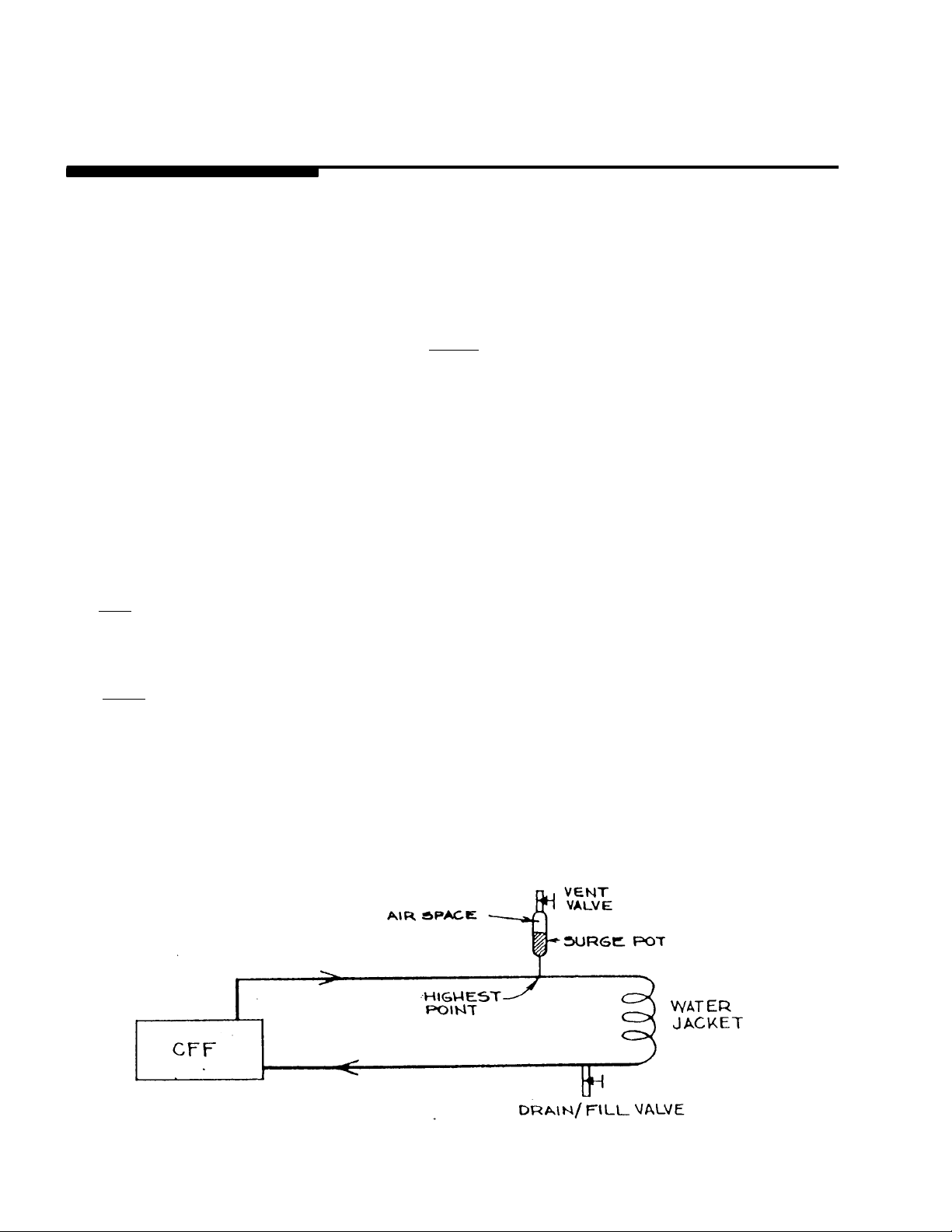
In closed systems (where the system is not open to the atmosphere), the installation should include a “surge
pot” located at the highest point in the outlet line, to facilitate proper purging of air and to allow for expansion
and contraction of the liquid in the system with changes in temperature. This pot should normally have
approximately 1/10th the total volume of the system, and a small air space must remain at the top for proper
operation.
90538
FIGURE 1. TYPICAL CLOSED SYSTEM
2
Page 5

FIGURE 2. LIQUID CONNECTIONS
Electrical Connections
All wiring must conform to NEC and local codes. The unit must be permanently wired by means of conduit. The
conduit should be run through the hole provided in the rear of the cabinet and connected by means of a fitting to
the 1/2” knockout in the electric box. The field supply wires must be spliced to the pigtails provided in the
electric box. Take care to keep all wiring away from the relay, to avoid interfering with its proper operations.
Do not operate the unit until the start–up procedure has been followed.
START UP
When the installation steps have been completed, the system is ready to fill. With the power switch “off” begin
adding liquid to the system until the inlet hose and pump housing are completely full. This will occur
automatically if the unit has been properly installed. If this priming action does not occur, go back and review the
installation to be sure that there are no restrictions or air traps in the inlet hose. Once the inlet hose is full, the
pump may be started by turning the power switch “on”. As liquid is pumped through the system, air will be
expelled from the outlet hose. (In closed systems, the vent valve must be opened to allow air to escape from the
system).
Once the pump has been started, it is important to add liquid at a sufficient rate so the inlet hose remains full.
Continue adding liquid until all of the air has been expelled and the liquid is at its normal operating level.
After filling, check all connections for tightness. In many cases, a leaking connection on the inlet side of the
pump will allow air to enter the system. This can be observed as a stream of bubbles in the hose accompanied
by a “growling” noise in the pump. If not eliminated, this air can interfere with proper system operation and will
shorten the pump life.
Once the system has been properly filled and purged of air, it will maintain its prime automatically when the unit
is shut off. The above procedure needs to be repeated only if the system has be drained.
3
90538
Page 6

OPERATION
The unit may be turned on and off by means of the power switch. The pilot light indicates the presence of power
when the switch is “On”. Setting the thermostat dial to the desired temperature will cause either the heater of
cooling system to operate, depending on the liquid temperature. In applications requiring extreme accuracy, a
thermometer should be used in the liquid bath to determine the temperature.
In operation, the circulating pump runs continuously, drawing liquid from the system and pumping it through the
tank and back out to the system. The 2-stage thermostat senses the liquid temperature in the tank and cycles
the heater or cooling system in response to temperature changes below or above the setpoint respectively.
Heating is accomplished by means of an immersion heater located at one end of the tank. The cooling system
is completely sealed and consists of t compressor, condenser, receiver, thermal expansion valve, and a heat
exchanger which is an integral part of the tank. It utilizes refrigerant 12 to remove heat from the liquid in the
tank.
MAINTENANCE
The CFF requires very little normal maintenance. The condenser fins should be cleaned occasionally with a
brush or compressed air to keep them from becoming blocked by dirt. If the unit is to be shut off for a prolonged
period, it should be flushed with clean water and then drained completely. Every 6 months, the pump should be
oiled with SAE 20 non-detergent oil at the two motor oil ports.
Except for the refrigeration system, the CFF is easily serviced in the field should the need arise. The following
section will serve as a guide to making general repairs.
Pump
The pump consists of only one moving part, the impeller, which is magnetically driven by and open type,
thermally protected motor. The magnetic drive construction eliminates shaft seals and their associated leak
problem. The most common source of pump failure is dry operation, which causes the impeller to bind.
The pump is easily disassembled when required by removing the 4 wing nuts which hold it together. Figure 3
shows the major pump components and their assembly.
90538
FIGURE 3. MAJOR PUMP COMPONENTS AND THEIR ASSEMBLY
4
Page 7

Heater
The immersion heater is instaled in a threaded connection in the tank. Electrical connections are by means of
slip-on terminals. When installing a new heater, teflon tape should be used on the threads to insure leak-proof
seal.
Cooling System
The cooling system is hermetically sealed, and repairs to the refrigeration components should only be made by
he factory. Field replaceable parts include the compressor electrical equipment and the condenser fan.
The compressor electrical equipment consists of a thermal protector, starting relay, and starting capacitor. All
are located in the compressor terminal box. Care should be taken to see that the wires are reconnected
properly when replacing these components.
Thermostat
NOTE: The thermostat consists of a temperature actuated bellows assembly which operates two micro
switches, at slightly different temperatures, to control the heating or cooling of the liquid in the tank. The internal
thermostat parts are not field replaceable of adjustable. In case of any failure, the thermostat should be
replaced.
When replacing the thermostat, note the routing of the capillary, and be sure to avoid any kinks or sharp bends.
The bulb is located in a well in the tank and can be removed or replaced simply by sliding in and out. When
reinstalling a new thermostat, the bulb should be coated with a heat conducting compound such as silicone
grease or “Thermal Mastic”. which is available at most refrigeration supply houses.
5
90538
Page 8

TROUBLESHOOTING
Trouble Probable Cause
UNIT NOT OPERATING. POWER LIGHT OFF A. Power switch off.
UNIT DOES NOT PUMP LIQUID. A. Pump motor burned out of pump impeller frozen.
B. Restriction or air trap in inlet line.
C. Restriction in outlet line.
UNIT DOES NOT HEAT. A. Heater burned out.
B. Bad “heat” switch on thermostat.
UNIT DOES NOT COOL; COMPRESSOR
RUNS.
COMPRESSOR DOESN’T RUN; BODY COOL A. Bad “cool” switch on thermostat.
COMPRESSOR DOESN’T RUN; BODY HOT A. Bad starting relay.
SYSTEM TEMPERATURE ERRATIC. A. Air in system.
A. Fan motor burned out.
B. * Refrigerant leak.
C. *Bad Expansion valve
B. Bad thermal protector.
C. Bad control relay in electric box.
D. *Compressor burned out.
B. Bad start capacitor.
C. * Compressor burned out.
B. Bad thermostat.
690538
Page 9

FIGURE 4. CIRCULATOR DIMENSIONS
7 90538
Page 10

NC
NO
RED
C
RED
BLACK
SW
H5/1/60
HTS
NC
H
REAR
VIEW
NO
C
TEMP.
INCR
START
RELAY
OL
C
CR
START
CAP.
R
S
C
WHITE
GRN
FIGURE 5. MODEL CFF WIRING DIAGRAM
LEGEND
P PUMP CR CONTROL RELAY
T THERMOSTAT C COMPRESSOR
F FAN H HEATER
SW POWER SWITCH L PILOT LIGHT
HTS HI-TEMP. SWITCH OL OVERLOAD
890538
Page 11

CFF PERFORMANCE DATA
heating capacity = 3412 BTUH (858K-CAL/HR)
All data is based on water
4000
(1008)
3000
(756)
2000
(504)
1000
(252)
40(4.4)
COOLING CAPACITY
50 (10.0)
BATH TEMPERATURE - °F (°C)
@ 75°F AMBIENT
(23.9 °C)
PUMP DATA
EXT. HEAD
FT. (METERS)
1 (0.3)
3 (0.9)
6(1.8)
60 (15.6)
FLOW RATE
GPM (LITER/MIN
4.9(18.6)
3.5(13.2)
1.1( 4.1)
70 (21.1)
80
(25.7)
70
(21.1)
60
(15.6)
50
(10)
40
(4.4)
‘130
RATE OF TEMP. CHANGE
10 GAL. SYSTEM (38 LITERS)
@ 75°F(23.9°C) AMBIENT
WELL INSULATED
0
30
60
90
120
(54.4)
120
48.9
110
(43.3)
100
(37.8)
90
(32.2)
TIME (MIN)
9 90538
Page 12

IMI CORNELIUS INC.
ONE CORNELIUS PLACE
ANOKA, MN. 55303–6234
TELEPHONE (800) 238–3600
FACSIMILE (612) 422–3232
TECH SVC 1-800-535-4240
WARRANTY
IMI Cornelius Inc. and Remcor Products Company warrants that all equipment and parts are free from
defects in material and workmanship under normal use and service. For a copy of the warranty applicable
to your Cornelius and or Remcor product, in your country, please write, fax or telephone the
IMI Cornelius office nearest you. Please provide the equipment model number, serial number and the
date of purchase.
IMI Cornelius Offices
AUSTRALIA D P.O. 210, D RIVERWOOD, D NSW 2210, AUSTRALIA D (61) 2 533 3122 D FAX (61) 2 534 2166
D AM LANGEN FELDE 32 D A-1222 D VIENNA, AUSTRIA D (43) 1 233 520 D FAX (43) 1-2335-2930
AUSTRIA
D BOSKAPELLEI 122 D B-2930 BRAASCHAAT, BELGIUM D (32) 3 664 0552 D FAX (32) 3 665 2307
BELGIUM
D RUA ITAOCARA 97 D TOMAS COELHO D RIO DE JANEIRO, BRAZIL D (55) 21 591 7150 D FAX (55) 21 593 1829
BRAZIL
D TYTHING ROAD ALCESTER D WARWICKSHIRE, B49 6 EU, ENGLAND D (44) 789 763 101 D FAX (44) 789 763 644
ENGLAND
FRANCE
D 71 ROUTE DE ST. DENIS D F-95170 DE UIL LA BARRE D PARIS, FRANCE D (33) 1 34 28 6200 D FAX (33) 1 34 28 6201
GERMANY
GREECE
HONG
ITALY
NEW
SINGAPORE
SPAIN
USA
D CARL LEVERKUS STRASSE 15 D D-4018 LANGENFELD, GERMANY D (49) 2173 7930 D FAX (49) 2173 77 438
D 488 MESSOGION AVENUE D AGIA PARASKEVI D 153 42 D ATHENS, GREECE D (30) 1 600 1073 D FAX (30) 1 601 2491
KONG D 1104 TAIKOTSUI CENTRE D 11-15 KOK CHEUNG ST D TAIKOKTSUE, HONG KONG D (852) 789 9882 D FAX (852) 391 6222
D VIA PELLIZZARI 11 D 1-20059 D VIMARCATE, IT ALY D (39) 39 608 0817 D FAX (39) 39 608 0814
ZEALAND D 20 LANSFORD CRES. D P.O. BOX 19-044 AVONDALE D AUCKLAND 7, NEW ZEALAND D (64) 9 8200 357 D FAX (64) 9 8200 361
D 16 TUAS STREET D SINGAPORE 2263 D (65) 862 5542 D FAX (65) 862 5604
D POLIGONO INDUSTRAIL D RIERA DEL FONOLLAR D E-08830 SANT BOI DE LLOBREGAT D BARCELONA, SPA IN D (34) 3 640 2839 D FAX (34) 3 654 3379
D ONE CORNELIUS PLACE D ANOKA, MINNESOTA D (612) 421-6120 D FAX (612) 422-3255
90538
10
SD 99-3
1/16/96
Page 13

CORPORATE HEADQUARTERS:
Glendale Heights, IL 60139
Remcor Incorporated
500 Regency Drive
708. 980.6900
 Loading...