

Page 1
IMI CORNELIUS INC g One Cornelius Place g Anoka, MN 55303-6234
Telephone (800) 238-3600 Facsimile (612) 422-3246
Operator’s Manual
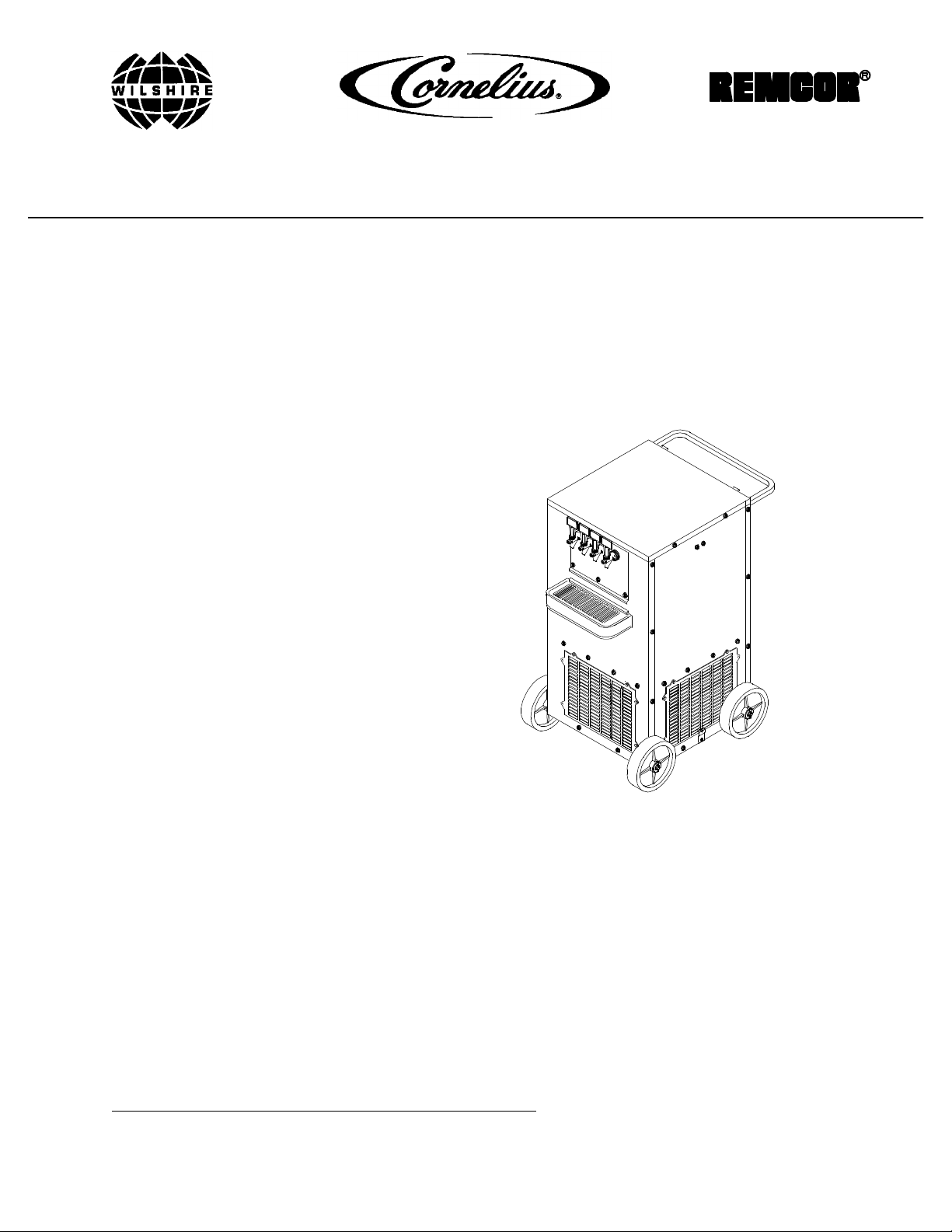
C-1550XR UNIVERSAL PRE-MIX DISPENSER
(R-404A REFRIGERANT)
Part No. 309989002
January 7, 1986
Revised: January 27, 1999
Control Code A
THIS DOCUMENT CONTAINS IMPORTANT INFORMATION
This Manual must be read and understood before installing or operating this equipment
IMI CORNELIUS INC; 1986--99Ó
PRINTED IN U.S.A
Page 2

TABLE OF CONTENTS
SAFETY INFORMATION 1. . . . . . . . . . . . . . . . . . . . . . . . . . . . . . . . . . . . . . . . . . . . . . . . . . . .
RECOGNIZE SAFETY INFORMATION 1. . . . . . . . . . . . . . . . . . . . . . . . . . . . . . . . . .
UNDERSTAND SIGNAL WORDS 1. . . . . . . . . . . . . . . . . . . . . . . . . . . . . . . . . . . . . . .
FOLLOW SAFETY INSTRUCTIONS 1. . . . . . . . . . . . . . . . . . . . . . . . . . . . . . . . . . . .
CO2 (CARBON DIOXIDE) WARNING 1. . . . . . . . . . . . . . . . . . . . . . . . . . . . . . . . . . .
SHIPPING, STORING, OR RELOCATING UNIT 1. . . . . . . . . . . . . . . . . . . . . . . . . .
GENERAL INFORMATION 3. . . . . . . . . . . . . . . . . . . . . . . . . . . . . . . . . . . . . . . . . . . . . . . . . .
TO THE USER OF THIS MANUAL 3. . . . . . . . . . . . . . . . . . . . . . . . . . . . . . . . . . . . . . .
WARRANTY REFERENCE INFORMATION 3. . . . . . . . . . . . . . . . . . . . . . . . . . . . . . .
OPERA TOR’S INSTRUCTIONS 5. . . . . . . . . . . . . . . . . . . . . . . . . . . . . . . . . . . . . . . . . . . . .
OPERATING CONTROLS 5. . . . . . . . . . . . . . . . . . . . . . . . . . . . . . . . . . . . . . . . . . . . . .
DISPENSING VALVE LEVER 5. . . . . . . . . . . . . . . . . . . . . . . . . . . . . . . . . . . . . . . . . .
UNIT POWER SWITCH (115 VAC, 60 HZ UNITS ONLY) 5. . . . . . . . . . . . . . . . . . .
UNIT OPERATION 6. . . . . . . . . . . . . . . . . . . . . . . . . . . . . . . . . . . . . . . . . . . . . . . . . . . . .
DAILY PRE-OPERATION CHECK 6. . . . . . . . . . . . . . . . . . . . . . . . . . . . . . . . . . . . . . . .
ADJUSTMENTS 6. . . . . . . . . . . . . . . . . . . . . . . . . . . . . . . . . . . . . . . . . . . . . . . . . . . . . . .
ADJUSTING PRODUCT TANKS CO2 REGULATORS 6. . . . . . . . . . . . . . . . . . . . .
ADJUSTING DISPENSED PRODUCT FLOW RATE 6. . . . . . . . . . . . . . . . . . . . . .
REPLENISHING CO2 SUPPLY 6. . . . . . . . . . . . . . . . . . . . . . . . . . . . . . . . . . . . . . . . . .
REPLENISHING PRODUCT SUPPLY 7. . . . . . . . . . . . . . . . . . . . . . . . . . . . . . . . . . . .
PRODUCT FLAVOR CHANGE 7. . . . . . . . . . . . . . . . . . . . . . . . . . . . . . . . . . . . . . . . . .
CLEANING CONDENSER COIL 7. . . . . . . . . . . . . . . . . . . . . . . . . . . . . . . . . . . . . . . . .
CHECKING ICE WATER BATH 7. . . . . . . . . . . . . . . . . . . . . . . . . . . . . . . . . . . . . . . . . .
CLEANING AND SANITIZING 7. . . . . . . . . . . . . . . . . . . . . . . . . . . . . . . . . . . . . . . . . . .
DAILY CLEANING OF UNIT 7. . . . . . . . . . . . . . . . . . . . . . . . . . . . . . . . . . . . . . . . . . .
SANITIZING PRE-MIX SYSTEMS 8. . . . . . . . . . . . . . . . . . . . . . . . . . . . . . . . . . . . . .
TROUBLESHOOTING 11. . . . . . . . . . . . . . . . . . . . . . . . . . . . . . . . . . . . . . . . . . . . . . . . . . . . . .
Page
TROUBLESHOOTING PRODUCT SYSTEM 11. . . . . . . . . . . . . . . . . . . . . . . . . . . . . .
NO PRODUCT DISPENSED. 11. . . . . . . . . . . . . . . . . . . . . . . . . . . . . . . . . . . . . . . . . .
DISPENSED PRODUCT COMES OUT OF DISPENSING VALVE CLEAR BUT
FOAMS IN CUP OR GLASS 11. . . . . . . . . . . . . . . . . . . . . . . . . . . . . . . . . . . . . . . . . . .
DISPENSED PRODUCT FOAMS AS IT LEAVES DISPENSING VALVE. 11. . . . .
TROUBLESHOOTING REFRIGERATION SYSTEM 11. . . . . . . . . . . . . . . . . . . . . . . .
REFRIGERATION SYSTEM COMPRESSOR DOES NOT OPERATE 11. . . . . . .
REFRIGERATION SYSTEM COMPRESSOR OPERATES CONTINUOUSLY
BUT DOES NOT FORM SUFFICIENT ICE BANK. 12. . . . . . . . . . . . . . . . . . . . . . . .
WARRANTY 13. . . . . . . . . . . . . . . . . . . . . . . . . . . . . . . . . . . . . . . . . . . . . . . . . . . . . . . . . . . . . .
LIST OF FIGURES
FIGURE 1. UNIVERSAL C--1550XR (FOUR-FLAVOR UNIT SHOWN) 5. . . . . . . .
LIST OF TABLES
TABLE 1. DESIGN DATA 3. . . . . . . . . . . . . . . . . . . . . . . . . . . . . . . . . . . . . . . . . . . . . . .
i
309989002
Page 3
SAFETY INFORMATION
Recognize Safety Information
This is the safety-alert symbol. When you see this
symbol on our machine or in this manual, be alert to
the potentially of personal injury .
Follow recommended precautions and safe operating
practices.
Understand Signal Words
A signal word - DANGER, WARNING, OR CAUTION
is used with the safety-alert symbol. DANGER identifies the most serious hazards.
DANGER
Safety signs with signal word DANGER or WARNING
are typically near specific hazards.
General precautions are listed on CAUTION safety
signs. CAUTION also calls attention to safety messages in this manual.
WARNING
CAUTION
Follow Safety Instructions
Carefully read all safety messages in this manual and on your machine safety signs. Keep safety signs in
good condition. Replace missing or damaged safety signs. Learn how to operate the machine and how to
use the controls properly. Do not let anyone operate the machine without instructions. Keep your machine in
proper working condition. Unauthorized modifications to the machine may impair function and/or safety and
affect the machine life.
CO2(Carbon Dioxide) Warning
CO2Displaces Oxygen. Strict Attention must be observed in the prevention of CO2(carbon dioxide)
gas leaks in the entire CO2and soft drink system. If a CO2gas leak is suspected, particularly in a
small area, immediately ventilate the contaminated area before attempting to repair the leak. Personnel exposed to high concentration of CO2gas will experience tremors which are followed rapidly by
loss of consciousness and suffocation.
Shipping, Storing, Or Relocating Unit
CAUTION: Before shipping, relocating, or storing this Unit, the product coils must be flushed with
potable water, all water must be purged from the product coils, ice bank must be melted, and water
must be drained from the water tank. A freezing ambient environment will cause residual water remaining inside the Unit to freeze resulting in damage to the Unit internal components.
1 309989002
Page 4

THIS PAGE LEFT BLANK INTENTIONALLY
2309989002
Page 5
GENERAL INFORMATION
TO THE USER OF THIS MANUAL
This is an Operator’s Manual for the C-1550XR Universal Pre-Mix Dispenser (hereafter referred to as a Unit).
Retain this manual for future reference.
This section covers WARRANTY REFERENCE INFORMATION and DESIGN DATA information for the
C-1550XR Universal Pre-Mix Dispenser. This Unit contains no User serviceable parts.
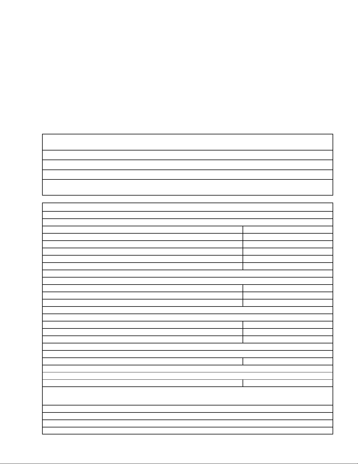
WARRANTY REFERENCE INFORMATION
Warranty Registration Date
(to be filled out by customer)
Unit Part Number:
Serial Number:
Install Date:
Local Authorized
Service Center:
Table 1. Design Data
Unit Part Numbers:
Universal C-1550XR Four-Flavor (115 VAC, 60 Hz) 2849749020
Universal C-1550XR Four-Flavor (115 VAC, 60 Hz) 2849749200
Universal C-1550XR Five-Flavor (115 VAC, 60 Hz) 2849759200
Universal C-1550XR Five-Flavor (115 VAC, 60 Hz) 2849759020
Universal C-1550XR Five-Flavor (230 VAC, 50 Hz) 4949759020
Universal C-1550XR Five-Flavor (230 VAC, 50 Hz) 4949759200
Overall Dimensions:
Height 42-1/2 inches
Width 21 3/4-inches
Depth (with drip tray) 31-1/2 inches
Weights:
Dry Weight 170 pounds
With Water Tank Full of Water 403 pounds
Ice Bank Weight 100 pounds
Capacities:
Unit Water Bath (no ice bank) approx. 28 gallons
Dispensing Rate:
12-oz. drinks 8/minute 724 (see NOTE)
NOTE: *Number of 12-oz. drinks that can be dispensed at 40° F or below with 75° F product inlet temperature
and 75° F ambient.
Ambient Operating Temperature 40° F to 100° F
Electrical Requirements: See Unit Nameplate
3 309989002
Page 6

THIS PAGE LEFT BLANK INTENTIONALLY
309989002 4
Page 7

OPERATOR’S INSTRUCTIONS
This section covers operating controls, pre-operation check, Unit operation, and maintenance procedures that
may be performed by the Operator.
IMPORTANT: Only qualified Personnel should service internal components of the Unit.
CAUTION: This Unit is intended for indoor installation only. Do not install this Unit in an
outdoor environment which would expose it to the outside elements.
IMPORTANT: For the most efficient operation of the Unit, the ambient operating temperature for the
Unit should not exceed 90° F. Satisfactory temperatures may be obtained using blowers, air
conditioning, etc. Check your local codes.
WARNING: The Unit must be electrically grounded to avoid possible fatal electrical shock
or serious injury to the operator. The Unit power cord is equipped with a three-prong plug.
If a three-hole (grounded) electrical outlet is not available, use an approved method to
ground the Unit.
OPERATING CONTROLS
(see Figure 1)
DISPENSING VALVE LEVER
The dispensing valves levers need only be pulled forward to dispense product and released when cup or glass
is full.
UNIT POWER SWITCH (115 VAC, 60 HZ UNITS ONLY)
The Unit power switch, located on back of the Unit. must be in the “ON” (up) position before Unit will operate.
DISPENSING
VALVE (4)
DRIP TRAY/CUP REST
UNIT POWER SWITCH
(115 VAC UNITS ONLY)
FIGURE 1. UNIVERSAL C--1550XR (FOUR-FLAVOR UNIT SHOWN)
3099890025
Page 8

UNIT OPERATION
1. If applicable, make sure drip tray drain hose is routed to a waste container.
2. Make sure Unit power switch (115 VAC Units only), located on back side of the Unit, is in the “ON” (up)
position.
3. Hold cup or glass under the dispensing valve. Pull dispensing valve lever forward and dispense until cup or
glass is full, then release lever.
DAILY PRE-OPERATION CHECK
1. Make sure CO2cylinder regulator assembly 1800 psi gage indicator is not in shaded (“change CO2cylinder”) portion of the dial. If so, CO2cylinder is almost empty and must be replaced as instructed.
2. Be sure of sufficient product supply in all product tanks. If not, replenish product supply as instructed.
ADJUSTMENTS
ADJUSTING PRODUCT TANKS CO2REGULATORS
The product tanks CO2regulators should be periodically checked for proper pressure settings and if necessary,
be adjusted by a qualified Service Person.
ADJUSTING DISPENSED PRODUCT FLOW RATE
Dispensed product flow rate of the dispensing valves should be periodically checked and if necessary, be adjusted by a qualified Service Person.
REPLENISHING CO2SUPPLY
NOTE: When indicator on CO2cylinder regulator assembly 1800 psi gage is in shaded (‘‘change CO
cylinder’’) portion of dial, CO2cylinder is almost empty and should be replaced.
CAUTION: Wear protective eyewear to avoid injury from gas-driven particles.
WARNING: CO2displaces oxygen. Strict attention must be observed in the prevention of
CO2(carbon dioxide) gas leaks in the entire CO2and soft drink system. If a CO2gas leak is
suspected, particularly in a small area, immediately ventilate the contaminated area before
attempting to repair the leak. Personnel exposed to high concentration of CO2gas will experience
tremors which are followed rapidly by loss of consciousness and suffocation.
1. Fully close (clockwise) CO2cylinder valve.
2. Slowly loosen CO2regulator assembly coupling nut allowing CO2pressure to escape, then remove regulator assembly from empty CO2cylinder.
2
3. Unfasten safety chain and remove empty CO2cylinder.
WARNING: To avoid personal injury and/or property damage, always secure CO2cylinder
in an upright position with safety chain to prevent it from falling over. Should the shutoff
valve become accidentally broken off, CO2cylinder can cause serious personal injury.
309989002 6
Page 9

4. Position CO2cylinder and secure with safety chain.
5. Make sure gasket is in place inside CO2regulator coupling nut, then install regulator on CO2cylinder.
6. Open (counterclockwise) CO2cylinder valve slightly to allow lines to slowly fill with gas, then open valve
fully to back-seat valve. (Back-seating valve prevents leakage around valve shaft).
7. Check CO2connections for leaks.
REPLENISHING PRODUCT SUPPLY
1. Remove inlet (CO2) disconnect (grey) and outlet disconnect (black) from empty product tank, then remove
tank.
2. Place full product tank in position, then connect inlet (CO2) disconnect (grey) and outlet disconnect (black)
to tank.
PRODUCT FLAVOR CHANGE
Sanitize applicable system as instructed, then install full tank of new flavor product.
CLEANING CONDENSER COIL
NOTE: Air circulation through the condenser coil, required to cool the coil, is drawn in through grille
on Unit front panel and is exhausted out through grilles on sides and back of the Unit. Restricting air
flow through the condenser coil will decrease cooling efficiency of the Unit.
Area in front, sides, and back of the Unit must be kept free of obstructions at all times which would
prevent air flow in and out of the Unit.
An excessive accumulation of dust, lint, and grease on the condenser coil will restrict air flow through the coil
which will decrease cooling efficiency of the Unit. The Unit condenser coil should be periodically cleaned to
maintain cooling efficiency of the Unit. Contact a qualified Service Person to clean the Unit condenser coil.
CHECKING ICE WATER BATH
A gurgle heard from the Unit while it is operating, indicates the water level in the water tank is low and more
water should be added to the tank. Contact a qualified Service Person to replenish the water tank water supply
and if necessary, also clean the water tank.
CLEANING AND SANITIZING
DAILY CLEANING OF UNIT
NOTE: A drip tray that does not have a drain hose routed to a waste container or a permanent drain
must be removed from the Unit and be thoroughly cleaned. A drip tray that has a drip tray drain hose
routed to a waste container or a permanent drain may be cleaned in place on the Unit as follows.
3. Remove cup rest from the drip tray .
4. Wash drip tray in place on the Unit, then rinse drip tray with hot water allowing water to drain out through
the drain hose.
5. Wash cup rest, then rinse the cup rest with clean water. Install cup rest in drip tray.
6. Clean all external surfaces of the Unit with a sponge. Rinse out the sponge with clean water, then wring
excess water out of the sponge and wipe off all external surfaces of the Unit. Wipe Unit dry with a clean
soft cloth. DO NOT USE ABRASIVE-TYPE CLEANERS.
3099890027
Page 10

SANITIZING PRE-MIX SYSTEMS
IMPORTANT: Only qualified Service Personnel should perform sanitizing procedure on the pre-mix
product systems.
The pre-mix product systems should be sanitized every 90-days using a non-scented household liquid bleach
such as Hi-Lex or Chlorox containing a 5.25% sodium hypochlorite concentration. Proceed as follows to sanitize
the pre-mix product systems.
1. Disconnect product tanks from the product systems.
2. Rinse product tanks quick disconnects with warm potable water.
3. Using a clean empty product tank, prepare a full tank of non-scented liquid dishwasher detergent solution
by using 70° F (21° C) to 100° F (38° C) potable water and 0.5 oz. (15 ml) of liquid dishwasher detergent
(such as Joy, Ivory, etc.) to one gallon of potable water. Shake tank containing detergent solution to thoroughly mix the solution.
4. Connect tank containing detergent solution into one of the product systems.
5. Place waste container under the applicable dispensing valve.
6. Activate the dispensing valve to permit detergent solution to purge product out of the line, coil, and the dispensing valve. Continue to dispense until only detergent solution is dispensed from the dispensing valve.
7. Connect tank containing detergent solution into remaining product systems and flush product out of systems as instructed in steps 5 and 6 preceding.
8. Using a clean product tank, prepare sanitizing solution using 70° F (21° C) to 100° F (38° C) potable water
and 0.5 oz. (15 ml) of household liquid bleach such as non-scented Hi-Lex or Chlorox that contains a
5.25 % sodium hypochlorite concentration to one gallon of potable water. This mixture must not exceed
200 PPM of chlorine. Shake tank containing sanitizing solution to thoroughly mix the solution.
9. Connect tank containing sanitizing solution into one of the product systems.
10. Place waste container under the applicable dispensing valve.
11. Activate the dispensing valve for one minute to purge detergent solution from and install sanitizing solution
in the product system.
12. Continue activating the dispensing valve in cycles (“ON” for 15--seconds, “OFF”, then “ON” for
15-seconds). Repeat “ON” and “OFF” cycles for 15 cycles.
13. Repeat steps 9 through 11 preceding to purge detergent solution from the remaining product systems.
14. Allow sanitizing solution to remain in the product system for not less than 10-minutes or for no more than
15-minutes.
15. Connect product tank containing potable water into the product system to be flushed.
WARNING: Flush sanitizing solution from the system(s) as instructed. Residual sanitizing
solution left in the product system(s) could create a health hazard.
16. Place waste container under applicable dispensing valve.
17. Activate the dispensing valve for one minute to purge all sanitizing solution out of the product system.
18. Continue activating the dispensing valve in cycles (“ON” for 15--seconds, “OFF”, then “ON” for
15-seconds). Repeat “ON” and “OFF” cycles for 15 cycles.
19. Repeat steps 15 through 18 preceding to purge sanitizing solution from the remaining product systems.
309989002 8
Page 11

20. Remove product tank containing flush water from the product system, then connect a clean empty product
tank into the system.
21. Place waste container under applicable dispensing valve.
22. Activate the dispensing valve to purge all water from the product system.
23. Repeat steps 20 and 22 preceding to purge all water from the remaining product systems.
24. Dispose of waste sanitizing solution in a sanitary sewer, not in a storm drain, then thoroughly rinse the inside and the outside of the container that was used for sanitizing solution to remove all sanitizing solution
residue.
3099890029
Page 12

THIS PAGE LEFT BLANK INTENTIONALLY
10309989002
Page 13

TROUBLESHOOTING
IMPORTANT: Only qualified personnel should service internal components or electrical wiring.
WARNING: If repairs are to be made to a product system, remove quick disconnects from
the applicable product tank, then relieve the system pressure before proceeding. If repairs
are to be made to the CO2system, stop dispensing, shut off the CO2supply , then relieve
the system pressure before proceeding. If repairs are to be made to the refrigeration system, make
sure electrical power is disconnected from the Unit.
TROUBLESHOOTING PRODUCT SYSTEM
Trouble Probable Cause Remedy
NO PRODUCT DISPENSED. A. Product tank quick
disconnects not attached
properly .
B. No product supply (product
tank empty).
C. No CO2supply . C. Replenish CO2supply as
DISPENSED PRODUCT
COMES OUT OF
DISPENSING VALVE CLEAR
BUT FOAMS IN CUP OR
GLASS
NOTE: Crushed ice also causes dispensing problems. When dispensed drink hits sharp edges of ice,
carbonation is released from dispensed drink.
DISPENSED PRODUCT
FOAMS AS IT LEAVES
DISPENSING VALVE.
A. Oil film or soap scum in cup or
glass.
B. Ice used for finished drink is
sub-cooled.
A. Recovery rate of Unit
exceeded (ice bank depleted).
B. Product tanks CO2regulator
improperly adjusted.
A. Securely attach product tank
quick disconnects.
B. Replenish product supply as
instructed.
instructed.
A. Use clean cups and glasses.
B. Do not use ice directly from
freezer. Allow ice to become
‘‘wet’’ before using. (Refer to
following NOTE)
A. Allow ice bank to recover.
B. Contact a qualified Service
Person to adjust product tanks
CO2regulator
C. Dispensing valve restricted or
dirty .
D. Refrigeration system not
operating properly.
TROUBLESHOOTING REFRIGERATION SYSTEM
REFRIGERATION SYSTEM
COMPRESSOR DOES NOT
OPERATE
A. Ice bank sufficient. A. Refrigeration not called for.
B. Unit power cord unplugged or
Unit power switch in ‘‘OFF’’
(down) position.
C. Sanitize product system as
instructed.
D. Contact a qualified Service
Person.
B. Plug in Unit power cord or place
power switch in ‘‘ON’’ (up)
position.
11 309989002
Page 14

Trouble RemedyProbable Cause
REFRIGERATION SYSTEM
COMPRESSOR DOES NOT
OPERATE (CONT’D)
REFRIGERATION SYSTEM
COMPRESSOR OPERATES
CONTINUOUSLY BUT DOES
NOT FORM SUFFICIENT ICE
BANK.
C. No power source (blown fuse
or tripped circuit breaker).
D. Low voltage at compressor
terminals.
E. Inoperative refrigeration
system.
A. Cooling capacity is exceeded
by over-drawing drinks.
B. Unit located in excessively hot
area or air circulation through
condenser coil is restricted.
C. Refrigeration system leak. C. Contact a qualified Service
C. Replace fuse or reset circuit
breaker. (Note: Fuse or circuit
breaker are not part of unit.)
D. Voltage must be at least 103 volts
(115 VAC Unit) or 208 (230 VAC
Unit) at compressor terminals
when compressor is trying to
start.
E. Contact a qualified Service
Person.
A. Reduce amount of drinks drawn
per given time.
B. Relocate Unit or contact a
qualified Service Person to clean
the condenser coil.
Person to repair the refrigeration
system.
12309989002
Page 15

WARRANTY
IMI Cornelius Inc. warrants that all equipment and parts are free from defects in material and workmanship under normal use and service. For a copy of the warranty applicable to your Cornelius, Remcor or W ilshireproduct, in your country, please write, fax or telephone the IMI Cornelius office nearest you. Please provide the
equipment model number, serial number and the date of purchase.
IMI Cornelius Offices
AUSTRALIA D P.O. 210, D RIVERWOOD, D NSW 2210, AUSTRALIA D (61) 2 533 3122 D FAX (61) 2 534 2166
AUSTRIA D AM LANGEN FELDE 32 D A-1222 D VIENNA, AUSTRIA D (43) 1 233 520 D FAX (43) 1-2335-2930
BELGIUM D BOSKAPELLEI 122 D B-2930 BRAASCHAAT , BELGIUM D (32) 3 664 0552 D FAX (32) 3 665 2307
BRAZIL D RUA ITAOCARA 97 D TOMAS COELHO D RIO DE JANEIRO, BRAZIL D (55) 21 591 7150 D FAX (55) 21 593 1829
ENGLAND D TYTHING ROAD ALCESTER D WARWICKSHIRE, B49 6 EU, ENGLAND D (44) 789 763 101 D FAX (44) 789 763 644
FRANCE D 71 ROUTE DE ST. DENIS D F-95170 DEUIL LA BARRE D PARIS, FRANCE D (33) 1 34 28 6200 D FAX (33) 1 34 28 6201
GERMANY D CARL LEVERKUS STRASSE 15 D D-4018 LANGENFELD, GERMANY D (49) 2173 7930 D FAX (49) 2173 77 438
GREECE D 488 MESSOGION AVENUE D AGIA PARASKEVI D 153 42 D ATHENS, GREECE D (30) 1 600 1073 D FAX (30) 1 601 2491
HONG KONG D 1104 TAIKOTSUI CENTRE D 11-15 KOK CHEUNG ST D TAIKOKTSUE, HONG KONG D (852) 789 9882 D FAX (852) 391 6222
ITALY D VIA PELLIZZARI 11 D 1-20059 D VIMARCATE, ITALY D (39) 39 608 0817 D FAX (39) 39 608 0814
NEW ZEALAND D 20 LANSFORD CRES. D P.O. BOX 19-044 AVONDALE D AUCKLAND 7, NEW ZEALAND D (64) 9 8200 357 D FAX (64) 9 8200 361
SINGAPORE D 16 TUAS STREET D SINGAPORE 2263 D (65) 862 5542 D FAX (65) 862 5604
SPAIN D POLIGONO INDUSTRAIL D RIERA DEL FONOLLAR D E-08830 SANT BOI DE LLOBREGAT D BARCELONA, SPAIN D (34) 3 640 2839 D FAX (34) 3 654 3379
USA D ONE CORNELIUS PLACE D ANOKA, MINNESOTA D (612) 421-6120 D FAX (612) 422-3255
LD004
4/21/98
13 309989002
Page 16

Page 17

IMI CORNELIUS INC.
CORPORATE HEADQUARTERS:
One Cornelius Place
Anoka, Minnesota 55303-6234
(612) 421-6120
(800) 238-3600
 Loading...