

Page 1
IMI CORNELIUS INC One Cornelius Place Anoka, MN 55303-6234
Telephone (800) 238-3600 Facsimile (612) 422-3246
Service Manual
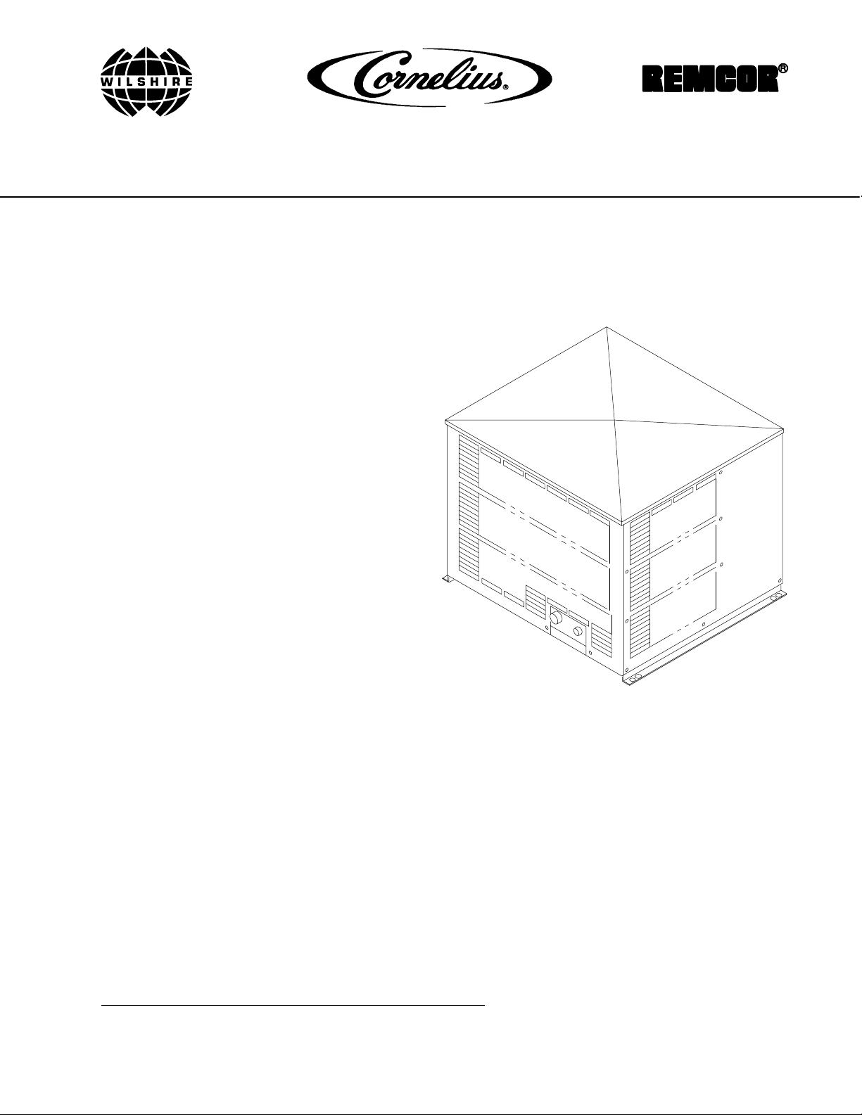
REMOTE CONDENSING UNIT
(PART NUMBERS 416117 AND 496117)
Part No. 1128
June 11, 1991
Revised: March 1, 1995
THIS DOCUMENT CONTAINS IMPORTANT INFORMATION
This Manual must be read and understood before installing or operating this equipment
IMI CORNELIUS INC; 1991
PRINTED IN U.S.A
Page 2

UNPACKING AND INSPECTION 2. . . . . . . . . . . . . . . . . . . . . . . . . . . .
SELECTING LOCATION 2. . . . . . . . . . . . . . . . . . . . . . . . . . . . . . . . . . . . . . . . . . .
INSTALLING REMOTE CONDENSING UNIT 2. . . . . . . . . . . . . . . . . . . . . .
SERVICE AND MAINTENANCE 3. . . . . . . . . . . . . . . . . . . . . . . . . . . . .
PERIODIC INSPECTION 3. . . . . . . . . . . . . . . . . . . . . . . . . . . . . . . . . . . . . . . . . . .
LUBRICATION 3. . . . . . . . . . . . . . . . . . . . . . . . . . . . . . . . . . . . . . . . . . . . . . . . . . .
CLEANING CONDENSER COIL 5. . . . . . . . . . . . . . . . . . . . . . . . . . . . . . . . . . . .
troubleshooting refrigeration compressor 7. . . . . . . . . . . . . . . . . . . . . . . . . . . . . . .
compressor cools but is very noisy especially when stopping and starting 7. . . . .
COMPRESSOR COOLS, BUT IS MODERATELY NOISY; LOUD ENOUGH TO BE NOĆ
TICED, BUT NO SHARP BANGS OR CLATTERING 7. . . . . . . . . . . . . .
COMPRESSOR OPERATES BUT REFRIGERATION SYSTEM DOES NOT COOL . . .
7
COMPRESSOR STARTS AND OPERATES FOR A FEW SECONDS, THEN STOPS . .
7
COMPRESSOR WILL NOT START 7. . . . . . . . . . . . . . . . . . . . . . . . . . . . . . . . . .
COMPRESSOR STARTS BUT WILL NOT OPERATE FOR MORE THAN A FEW SECĆ
ONDS 8. . . . . . . . . . . . . . . . . . . . . . . . . . . . . . . . . . . . . . . . . . . . . . . . . . . . . . . . .
Compressor starts but will not operate for more than a few seconds (cont'd) 9.
troubleshooting 10. . . . . . . . . . . . . . . . . . . . . . . . . . . . . . . . . . . . . . . . . . . . . . . . . . . .
TROUBLESHOOTING REMOTE CONDENSING UNIT 10. . . . . . . . . . . . . . .
COMPRESSOR DOES NOT OPERATE. 10. . . . . . . . . . . . . . . . . . . . . . . . . . . . . .
COMPRESSOR OPERATES CONTINUOUSLY BUT DOES NOT COOL SUFFICIENTĆ
LY 10. . . . . . . . . . . . . . . . . . . . . . . . . . . . . . . . . . . . . . . . . . . . . . . . . . . . . . . . . . . .
CONDENSER FAN MOTOR NOT OPERATING. 11. . . . . . . . . . . . . . . . . . . . . .
WARRANTY 16. . . . . . . . . . . . . . . . . . . . . . . . . . . . . . . . . . . . . . . . . . . . . . . . . . . . . .
7. . . . . . . . . . . . . . . . . . . . . . . . . . . . . . . . . . . . . . . . . . . . . . . . . . . . . . . . . . . . . . . . . . .
7. . . . . . . . . . . . . . . . . . . . . . . . . . . . . . . . . . . . . . . . . . . . . . . . . . . . . . . . . . . . . . . . . . .
7. . . . . . . . . . . . . . . . . . . . . . . . . . . . . . . . . . . . . . . . . . . . . . . . . . . . . . . . . . . . . . . . . . .
7. . . . . . . . . . . . . . . . . . . . . . . . . . . . . . . . . . . . . . . . . . . . . . . . . . . . . . . . . . . . . . . . . . .
8. . . . . . . . . . . . . . . . . . . . . . . . . . . . . . . . . . . . . . . . . . . . . . . . . . . . . . . . . . . . . . . . . . .
8. . . . . . . . . . . . . . . . . . . . . . . . . . . . . . . . . . . . . . . . . . . . . . . . . . . . . . . . . . . . . . . . . . .
10. . . . . . . . . . . . . . . . . . . . . . . . . . . . . . . . . . . . . . . . . . . . . . . . . . . . . . . . . . . . . . . . . . .
10. . . . . . . . . . . . . . . . . . . . . . . . . . . . . . . . . . . . . . . . . . . . . . . . . . . . . . . . . . . . . . . . . . .
10. . . . . . . . . . . . . . . . . . . . . . . . . . . . . . . . . . . . . . . . . . . . . . . . . . . . . . . . . . . . . . . . . . .
10. . . . . . . . . . . . . . . . . . . . . . . . . . . . . . . . . . . . . . . . . . . . . . . . . . . . . . . . . . . . . . . . . . .
10. . . . . . . . . . . . . . . . . . . . . . . . . . . . . . . . . . . . . . . . . . . . . . . . . . . . . . . . . . . . . . . . . . .
10. . . . . . . . . . . . . . . . . . . . . . . . . . . . . . . . . . . . . . . . . . . . . . . . . . . . . . . . . . . . . . . . . . .
10. . . . . . . . . . . . . . . . . . . . . . . . . . . . . . . . . . . . . . . . . . . . . . . . . . . . . . . . . . . . . . . . . . .
10. . . . . . . . . . . . . . . . . . . . . . . . . . . . . . . . . . . . . . . . . . . . . . . . . . . . . . . . . . . . . . . . . . .
10. . . . . . . . . . . . . . . . . . . . . . . . . . . . . . . . . . . . . . . . . . . . . . . . . . . . . . . . . . . . . . . . . . .
10. . . . . . . . . . . . . . . . . . . . . . . . . . . . . . . . . . . . . . . . . . . . . . . . . . . . . . . . . . . . . . . . . . .
10. . . . . . . . . . . . . . . . . . . . . . . . . . . . . . . . . . . . . . . . . . . . . . . . . . . . . . . . . . . . . . . . . . .
11. . . . . . . . . . . . . . . . . . . . . . . . . . . . . . . . . . . . . . . . . . . . . . . . . . . . . . . . . . . . . . . . . . .
11. . . . . . . . . . . . . . . . . . . . . . . . . . . . . . . . . . . . . . . . . . . . . . . . . . . . . . . . . . . . . . . . . . .
11. . . . . . . . . . . . . . . . . . . . . . . . . . . . . . . . . . . . . . . . . . . . . . . . . . . . . . . . . . . . . . . . . . .
Page 3
The Remote Condensing Unit P/N 416117 (230V, 60HZ) and P/N 496117 (230V, 50 HZ) consists basically of a
refrigeration compressor, a receiver tank, a fan cooled condenser coil, a head pressure control, and a
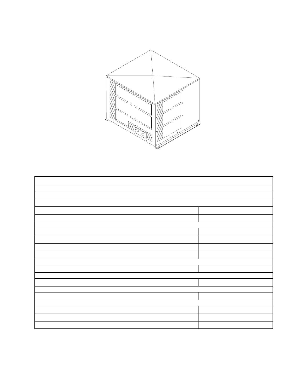
strainer/dryer mounted on an enclosed platform. The Remote Condensing Coil Unit (see FIGURE 1) is designed
to be used with any Evaporator Assembly with a rated temperature range of -10F to -32F. The Evaporator
Assembly is connected by refrigeration lines to and is refrigerated by the Remote Condensing Unit.
FIGURE 1. REMOTE CONDENSING UNIT
Table 1. Design Data
REMOTE CONDENSING UNIT
Part No.
230V, 60 HZ Unit 416117
230V, 50 HZ Unit 496117
Overall Dimensions:
Height 22-1/4 inches
Width 28-1/2 inches
Depth 25-3/4 inches
Shipping Weight (approx) 240 Pounds
Compressor Horsepower 2 H.P.
Ambient Operating Temperature –20 F to 120 F
Electrical Requirements:
Operating Voltage See Unit Nameplate
Current Draw See Unit Nameplate
1
1128
Page 4
UNPACKING AND INSPECTION
NOTE: The Remote Condensing Unit was thoroughly inspected before leaving the factory and the carrier has accepted and signed for it. Any damage or irregularities should be noted at time of delivery (or
not later than 15 days from date of delivery) and immediately reported to the delivering carrier. Request
a written inspection report from Claims Inspector to substantiate any necessary claim. File claim with
the delivering carrier, not with IMI Cornelius Inc.
1. Unpack Remote Condensing Unit. Remove all shipping tape and packing materials.
2. Inspect and make sure Remote Condensing Unit is in good condition as instructed in preceding NOTE.
SELECTING LOCATION
Locate the Remote Condensing Unit so the following requirements are satisfied:
1. The Remote Condensing Unit must be installed in a location which will allow shortest possible refrigeration
lines route from Condensing Unit to the Evaporator Assembly.
2. Close to a properly grounded 208/230 VAC 60HZ or 220/240 VAC 50HZ single-phase electrical circuit with
a 30-amp minimum-rated disconnect switch (not provided) fused at 25-amps (‘‘slow-blow’’) or power circuit
connected through an equivalent HACR circuit breaker must be available to the Unit. Use No. 8 AWG copper wire, or larger, depending upon line length, in suitable conduit or BX sheath. POWER CIRCUIT MUST
BE MADE UP OF COPPER CONDUCTORS AND ALL WIRING MUST CONFORM TO NATIONAL AND
LOCAL CODES. MAKE SURE UNIT IS PROPERLY GROUNDED.
3. An extreme warm climate installation may require extra caution in Remote Condensing Unit location. Avoid
hot sunny locations and seek shaded area if possible. If Remote Condensing Unit is to be installed on the
rooftop, the use of a structure to shade the Unit from direct sun exposure and/or a platform extending Unit
an additional 18–inches above the is highly recommended and will improve performance. Ample space
(24 inches on all sides and 48 inches above Unit) must be provided for proper air circulation through the
Unit and also access for service and maintenance. DO NOT BLOCK AIR CIRCULATION THROUGH THE
UNIT.
4. If the Remote Condensing Unit is installed on the rooftop, the Unit must be installed in a level position and
must be anchored with adequate fastening devices.
INSTALLING REMOTE CONDENSING UNIT
(see Figures 2, 3, and 4)
1. Install Remote Condensing Unit meeting requirements of SELECTING LOCATION. The Unit must be
installed in a level position and must be anchored with adequate fastening devices.
NOTE: The following Refrigeration Lines Kits are recommended to connect the Remote Condensing
Unit to the Evaporator Assembly.
Part No. Description
300598025 Refrigeration Lines Kit, 25-ft. long 90
300598050 Refrigeration Lines Kit, 50-ft. long 90
2. Route refrigeration lines from Remote Condensing Unit to the Evaporator Assembly.
3. Connect ends of refrigeration lines to Remote Condensing Unit refrigeration connectors.
4. Remove four screws securing Remote Condensing Unit top cover, then remove cover for access to electrical control box.
5. Remove one screw securing electrical control box cover, then remove cover.
1128
2
Page 5
WARNING: The Remote Condensing Unit must be electrically grounded to avoided
possible fatal electrical shock or serious injury to the operator. A green ground wire is
provided inside electrical control box to connect power circuit ground wire which
electrically grounds the Unit.
6. Connect 208/230 VAC 60HZ or 220/240 VAC 50 H
ments of SELECTING LOCATION) to L1 and L2 terminals on contactor inside the Unit electrical control box
as shown in FIGURE 4. MAKE SURE POWER CIRCUIT GREEN GROUND WIRE IS INSTALLED UNDER
GREEN GROUND SCREW INSIDE ELECTRICAL CONTROL BOX TO PROPERLY GROUND THE UNIT.
POWER CIRCUIT MUST BE MADE UP OF COPPER CONDUCTORS AND ALL WIRING MUST CONFORM TO NATIONAL AND LOCAL ELECTRICAL CODES.
7. A 24 VAC power circuit, which must conform to national and local electrical codes, must be routed and
connected between the Evaporator Assembly Temperature Control and the Remote Condensing Unit. Purpose of the 24VAC power control circuit is to allow the Evaporator Assembly Temperature Control to control ‘‘ON’’ and ‘‘OFF’’ operation of the Remote Condensing Unit. Route and connect 24VAC power control
circuit between the Evaporator Assembly and the Remote Condensing Unit as follows:
A. Route 24 VAC power control circuit electrical wires through hole in end panel to inside of the Remote
Condensing Unit.
B. Connect 24 VAC power control circuit electrical wires to labeled 24 V grey and red wires hanging out
of the electrical control box.
C. Install electrical control box cover and secure with screw.
D. Route 24VAC power control circuit from Remote Condensing Unit to the Evaporator Assembly loca-
tion.
E. Refer to manual provided with the Evaporator Assembly for instructions to connect 24VAC power cir-
cuit to Evaporator Assembly Temperature Control.
Single-Phase electrical power circuit (meeting require-
Z
SERVICE AND MAINTENANCE
WARNING: Disconnect electrical power to Remote Condensing Unit to prevent personal
injury before attempting any internal maintenance. Only qualified personnel should service
internal components or electrical wiring.
PERIODIC INSPECTION
Make sure Remote Condensing Unit Condenser Coil is free from debris. Restricting air through the condenser
coil will decrease the refrigeration systems cooling efficiency.
LUBRICATION
The Remote Condensing Unit condenser fan motor must be lubricated once every six months with S.A.E. 20W
oil. DO NOT OVER OIL.
3
1128
Page 6
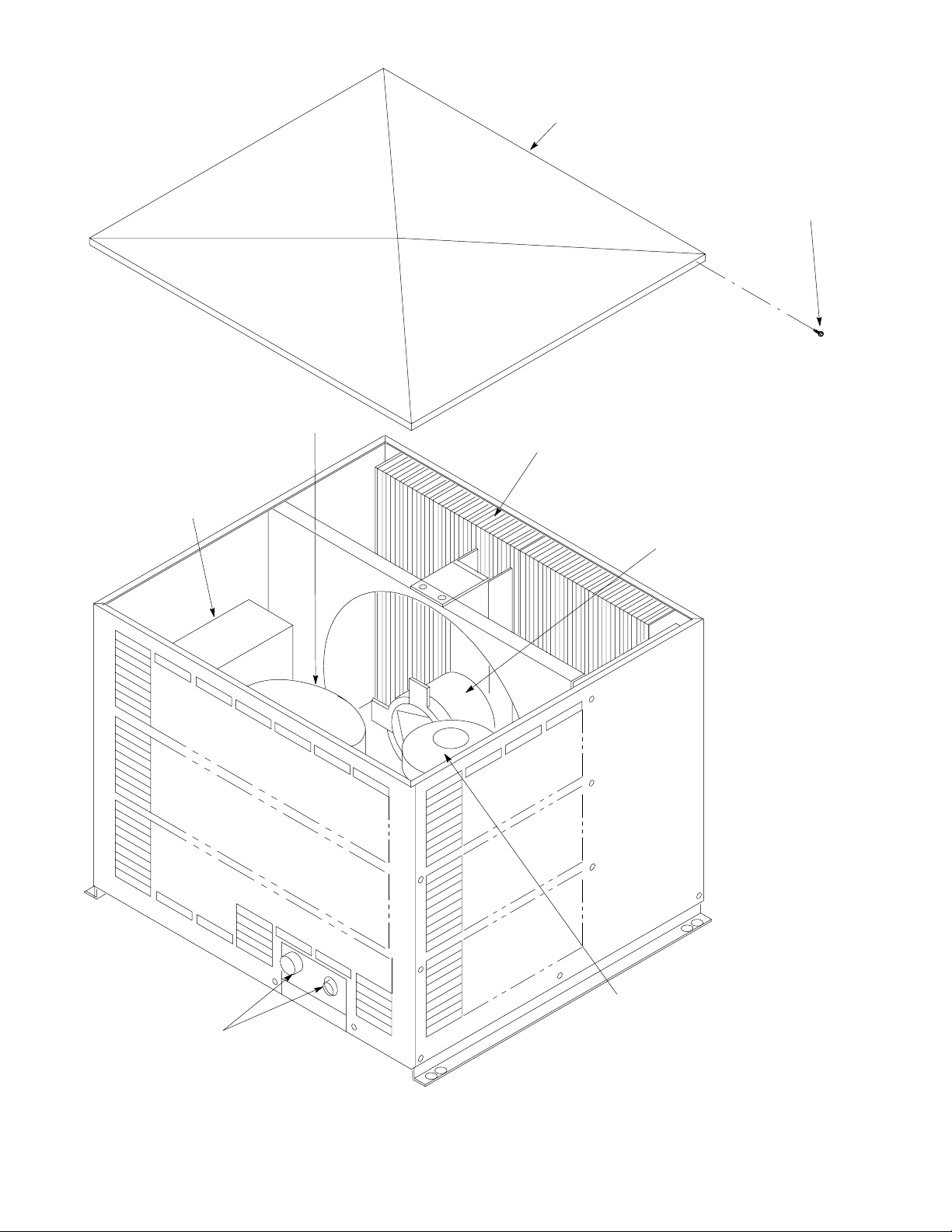
ELECTRICAL
CONTROL BOX
TOP COVER
TOP COVER
RETAINING SCREW(4)
COMPRESSOR
CONDENSER
COIL
CONDENSER
FAN MOTOR
REFRIGERATION
LINES CONNECTORS
1128
RECEIVER
TANK
FIGURE 2. PARTS IDENTIFICATION
4
Page 7

CLEANING CONDENSER COIL
CAUTION: Remote Condensing Unit is equipped with a condenser coil that must be
cleaned every 30 days. Allowing condenser coil to become clogged will cause refrigeration
system to overheat which will automatically shut refrigeration system down. After
condenser coil has been cleaned, high–pressure cutout sensing switch (located inside the Remote
Condensing Unit electrical control box) will automatically reset to restart the refrigeration system.
OPERATING IN THIS MANNER FOR PROLONGED PERIODS OF TIME COULD RESULT IN
COMPRESSOR FAILURE.
The Remote Condensing Unit condenser coil must be cleaned every 30 days. Circulating air, required to cool
the coil, is drawn in through the coil and is exhausted out through grilles on end and back of the Unit. Clean
condenser coil as follows:
1. Disconnect electrical power from Evaporator Assembly 24VAC Temperature Control.
2. Disconnect electrical power to Remote Condensing Unit at disconnect switch.
3. Remove four screws securing top cover on Remote Condensing Unit, then remove cover.
4. Clean condenser coil using vacuum cleaner, whisk broom, or a soft–bristle brush to remove any debris
from coil.
5. Make sure fan blade is not out of balance, is not bent, and is not striking any surface during rotation.
6. If the Remote Condensing Unit has been installed on the rooftop check and make sure roof area
immediately surrounding the Remote Condensing Unit is free and clear of any debris that may have
collected such as leaves, paper, trash, etc.
7. Install top cover on Remote Condensing Unit and secure with four screws.
8. Restore electrical power to Remote Condensing Unit at disconnect switch.
9. Restore electrical power to Evaporator Assembly 24VAC Temperature Control.
5
1128
Page 8

THIS PAGE LEFT BLANK INTENTIONALLY
1128
6
Page 9

TROUBLESHOOTING
IMPORTANT: Only qualified personnel should service internal components or electrical wiring.
WARNING: If repairs will be made to Remote Condensing Unit, turn off electrical power to
Evaporator Assembly, then disconnect power to Remote Condensing Unit at disconnect
switch before proceeding.
Trouble Probable Cause Remedy
TROUBLESHOOTING REFRIGERATION COMPRESSOR
COMPRESSOR COOLS BUT
IS VERY NOISY ESPECIALLY
WHEN STOPPING AND
STARTING
COMPRESSOR COOLS, BUT
IS MODERATELY NOISY;
LOUD ENOUGH TO BE
NOTICED, BUT NO SHARP
BANGS OR CLATTERING
COMPRESSOR OPERATES
BUT REFRIGERATION
SYSTEM DOES NOT COOL
A. Compressor cools, but is very
noisy, especially when
stopping and starting. This is
either a broken suspension
spring or loose crank shaft
extension.
A. Compressor cools but is
moderately noisy, loud enough
to be somewhat annoying, but
no sharp bangs or clattering.
A. Look for a refrigerant leak or
oil at tubing joints. If
compressor is moderately
noisy and no leaks are
evident, it is probably a broken
valve inside compressor
A. Compressor must be changed.
A. This is probably a discharge or
suction tube rattling inside the
compressor. If noise level can be
tolerated, compressor need not
be changed. The noise will not
affect the performance or shorten
compressor life.
A. Compressor must be changed.
COMPRESSOR STARTS AND
OPERATES FOR A FEW
SECONDS, THEN STOPS
COMPRESSOR WILL NOT
START
Note: If all above checks have been made and compressor will not start, increase start capacitor value
by about 15% and try to start. This can be done two ways: (The substitute capacitor must have voltage
rating equal to or greater than the existing start capacitor) a. Remove existing capacitor and replace with
one having a 15% greater MFD rating or (step b). b. Wire capacitor that has 15% of the MFD rating in paral-
lel with the existing capacitor. c. Try to start compressor. If all the previous (steps a and b) will not
make compressor operate, label compressor ‘‘stuck’’ and replace.
A. Compressor running too hot
due to condenser coils
plugged with dust, lint, and
grease restricting cooling air
flow through the condenser
coil.
A. Check line voltage across ‘‘T‘’
terminals on contactor.
B. loose or disconnected wires. B. Correct the loose or
C. Check control circuit; C. Contactor must pull in.
D. Examine start capacitor for
signs of excessive heat (blown
up). Check for open by
connecting test cord and
checking amp draw.
A. Clean condenser coil with vacuum
cleaner, low-pressure
compressed air, or soft brush,
then allow compressor to cool and
restart.
A. Voltage cannot be less than 208 V
(60 HZ Unit) or 220 V (50 HZ Unit)
nominal to start compressor.
disconnected wires.
D. If no current is drawn (or very
little), capacitor is open and must
be replaced.
If capacitor is blown, look for
inoperable start relay or low
voltage..
7
1128
Page 10

Trouble Probable Cause Remedy
COMPRESSOR STARTS BUT
WILL NOT OPERATE FOR
MORE THAN A FEW
SECONDS
WARNING: To avoid electrical shock even after electrical power has been disconnected
from Unit, run capacitor must be discharged by momentarily touching both capacitor
terminals at the same time using an insulated handled screwdriver.
A. Inoperable Start Relay.
Note: To check relay, remove
wire from No. 1 terminal on start
relay and touch to No. 2 terminal. Start compressor and immediately remove wire from No.
2 terminal. If compressor starts
and operates, problem is in the
start relay.
B. Low Voltage.
Note: Remove compressor terminals cover and connect voltmeter test leads between ‘‘C’’ (top
terminal) and ‘‘R’’ (lower right
terminal). Start compressor. A
minimum of 208 VAC (nominal)
must be present to operate compressor
A. Replace start relay.
B. If less than 208 V (60 HZ Unit) or
220 V (50 HZ Unit) is present,
upgrade Unit power source.
C. Inoperative Run Capacitor. C. Inspect capacitor for bulges,
cracks, or any external
deformation. If found, assume
capacitor is inoperable and
replace. If none of the above
conditions are evident, disconnect
wires from capacitor. Connect test
cord to capacitor terminals.
Connect ammeter to one wire of
test cord, Plug test cord into
electrical outlet and record amp
reading. *See formula on next
page at end of this trouble topic.
1128
8
Page 11

Trouble Probable Cause Remedy
COMPRESSOR STARTS BUT
WILL NOT OPERATE FOR
MORE THAN A FEW
SECONDS (CONT’D)
D. Grounded or Shorted Motor
Windings.
D. Disconnect all electrical wires
from compressor terminals. Set
ohmmeter on 100,000 ohm scale.
touch one lead to copper line or
bare metal of compressor. Touch
other lead to each of the
compressor terminals in
succession. Continuity must not
be indicated. If an ohmmeter
reading is obtained, then
compressor is grounded and must
be replaced. To check for shorted
windings, set ohmmeter on 10
ohm scale. Attach one lead to ‘‘C’’
(top terminal). The reading should
be approximately 1 to 1-1/2 ohms.
Leave one lead on ‘‘C‘’ terminal
and touch other lead to ‘‘S‘’ (lower
left terminal).The reading should
be 3-1/2 to 5 Ohms. Leave one
lead on ‘‘S’’ terminal and touch
other lead to ‘‘R’’ terminal. This
reading should be exactly the sum
of the first two readings obtained.
If the resistance readings do not
fall within these limits, the
compressor is ‘‘shorted’’ or has an
‘‘open’’ winding and must be
replaced. Replace compressor.
2650xAmp
*Use amps reading in formula
voltsń60HZ
= M.F.D. to determine actual value of capacitor. If calculated actual val-
ue is 10% more or less than rated value, replace capacitor.
9
1128
Page 12

TROUBLESHOOTING
IMPORTANT: Only qualified personnel should service internal components or electrical wiring.
WARNING: If repairs are to be made to a product system, remove quick disconnects from
the applicable product tank, then relieve the system pressure before proceeding. If repairs
are to be made to the CO
system, stop dispensing, shut off the CO
2
system pressure before proceeding. If repairs are to be made to the refrigeration system, make sure
electrical power is disconnected from the unit.
Trouble Probable Cause Remedy
TROUBLESHOOTING REMOTE CONDENSING UNIT
supply, then relieve the
2
COMPRESSOR DOES NOT
OPERATE.
A. Evaporator Assembly not
A. Refrigeration not called for.
calling for refrigeration.
B. Electrical power to Remote
Condensing Unit turned off.
C. Electrical power to Evaporator
Assembly turned off.
D. No Remote Condensing Unit
power source. Blown fuse or
B. Turn on electrical power to
Remote Condensing Unit.
C. Turn on electrical power to
Evaporator Assembly.
D. Replace fuse or reset circuit
breaker.
tripped circuit breaker.
E. Loose, disconnected, or
broken wiring.
F. High–pressure cutout switch
tripped.
E. Tighten connections or replace
broken wiring
F. High-pressure cutout switch will
automatically reset after
refrigeration system pressure has
lowered (see CAUTION note
under CLEANING CONDENSER
COIL).
G. Low voltage. G. Voltage must be at least 208 V
(60 HZ Unit) or 220 V (50 HZ Unit)
nominal at compressor terminals
when compressor is trying to
start.
COMPRESSOR OPERATES
CONTINUOUSLY BUT DOES
NOT COOL SUFFICIENTLY
1128
H. Inoperable run capacitor, or
H. Replace inoperable part.
start relay.
I. Inoperable compressor. I. Replace compressor.
A. Refrigeration capacity is
exceeded by product
A. Reduce amount of product drawn
per given time.
overdrawing.
B. Air circulation through Remote
Condensing Unit condenser
B. Check and if necessary, clean
condenser coil as instructed.
coil is restricted.
C. Insufficient refrigerant charge. C. Check Remote Condensing Unit
sight glass for bubbles or liquid
break. Find and repair
refrigeration leak, then replenish
refrigerant charge.
10
Page 13

Trouble RemedyProbable Cause
CONDENSER FAN MOTOR
NOT OPERATING.
A. Fan blade obstructed A. Remove obstruction.
B. Inoperative condenser fan
B. Replace condenser fan motor.
motor.
C. Compressor contactor
C. Replace compressor contactor.
inoperable.
D. Disconnected or broken
electrical wire.
D. Connect or repair broken
electrical wire.
11
1128
Page 14

STRAINER/DRYER HIGH-PRESSURE
PROCESS
LINE
CUTOUT SWITCH
SIGHT GLASS
COMPRESSOR
CONDENSER
FAN/HEATER
REFRIGERATION
LINES
SWITCH
RECEIVER
TANK
HEAD PRESSURE
CONTROL
SERVICE V ALVE (2)
CONDENSER
MOTOR/FAN
EVAPORATOR
ASSEMBLY
REMOTE ROOFTOP
CONDENSING UNIT
CONDENSER COIL
1128
FIGURE 3. REFRIGERATION FLOW DIAGRAM
12
Page 15

4
FIGURE 4. WIRING DIAGRAM
(REMOTE CONDENSING UNIT)
13
1128
Page 16

41.
25.
34.
1.
37.
36.
35.
32.
33.
43.
26.
2.
1.
6.
9.
1.
28.
42.
30.
29.
31.
1.
27.
21.
1.
1.
22.
24.
46.
44.
1.
5.
1.
42.
17.
12.
13.
14.
15.
16.
19.
20.
1.
1.
7.
18.
8.
1.
11.
10.
45.
1128
10.
38.
23.
4.
1.
3.
FIGURE 5. REMOTE CONDENSER ASS’Y
14
1.
Page 17

REMOTE CONDENSER ASS’Y (CON’T)
Item Part No. Description
416117 Remote Condenser Ass’y, 230V 60HZ
496117 Remote Condenser Ass’y, 230V 50HZ
1. *319941 Thread Rolling Screw , SL Hex Washer HD. No. 8-32 By 3/8 in. Long
2. 324153-068 Cover, Remote Condenser
3. 324151-068 Panel, Right-Side
4. 324152-068 Panel, Back
5. 324150-068 Panel, Left-Side
6. 324148 Condenser Coil
7. 309215 Pressure Control
8. 319871 Dryer
9. 319882 Sight-Glass
10. *189429 Hex Nut, 1/4-20
11. 324198 Receiver
12. *186146 Hex Nut, 5/16-18
13. *186148 Washer, Lock, .319 I.D.
14. 320737 Washer .343 I.D.
15. 325530 Spacer
16. 325529 Grommet
17. 324147 Compressor, 230V 60HZ
2240 Compressor, 230V 50HZ
18. 309919 Flange, 3/8
19. 309920 Flange, 1/2
20. 309895-011 Bracket, Coupler
21. 324155 Bracket, Motor
22. 324144 Motor, 1/6 H.P., 230V. 60HZ
2115 Motor, 1/6 H.P., 230V. 50HZ
23. 324145 Blade, Fan
24. 324154 Shroud
25. 324146 Control Box
26. 324156 Cover, Control Box
27. 324172 Strap, Capacitor Fan
28. 324143 Capacitor, Start, Fan
29. 325956 Strap, Capacitor
30. 325939 Capacitor, Run, 230V 60HZ
2162 Capacitor, Run, 230V 50HZ
31. 325938 Capacitor, Start
32. 325940 Relay, Start, 230V 60HZ
197466 Relay, Start, 230V 50HZ
33. 324209 Pressure Switch, HI, 200 PSI
34. 329473 Contactor, 2 4 V.
35. *325069 Machine Screw, S: Hex HD, No. 10-24 by 1/2-in. Long
36. 325145 Washer, # 1 0
37. 325644 Lug
38. 324149-068 Base
39. *187552 Machine Screw, Phil RD HD, No. 8-32 by 1/4-in. Long (Not Shown)
40. 309524-011 Cord (Not Shown)
41. 320734 Self-Threaded Screw, Phil Pan HD. No. 6-32 by 3/8-in. Long
42. 313802 Snap Bushing
43. 324208 Pressure Switch, HI, 475 PSI
44. 319960-005 Edging, Grommet
45. 324215 Heater, 138 Watt, 220V. 60Hz
46. 321818 Button Plug
15
1128
Page 18

WARRANTY
IMI Cornelius Inc. warrants that all equipment and parts are free from defects in material and workmanship under normal use and service. For a copy of the warranty applicable to your Cornelius, Remcor or Wilshire product, in your country, please write, fax or telephone the IMI Cornelius office nearest you. Please provide the
equipment model number, serial number and the date of purchase.
IMI Cornelius Offices
AUSTRALIA P.O. 210, RIVERWOOD, NSW 2210, AUSTRALIA (61) 2 533 3122 FAX (61) 2 534 2166
AM LANGEN FELDE 32 A-1222 VIENNA, AUSTRIA (43) 1 233 520 FAX (43) 1-2335-2930
AUSTRIA
BOSKAPELLEI 122 B-2930 BRAASCHAAT, BELGIUM (32) 3 664 0552 FAX (32) 3 665 2307
BELGIUM
RUA ITAOCARA 97 TOMAS COELHO RIO DE JANEIRO, BRAZIL (55) 21 591 7150 FAX (55) 21 593 1829
BRAZIL
ENGLAND
TYTHING ROAD ALCESTER WARWICKSHIRE, B49 6 EU, ENGLAND (44) 789 763 101 FAX (44) 789 763 644
71 ROUTE DE ST. DENIS F-95170 DEUIL LA BARRE PAR IS, FRANCE (33) 1 34 28 6200 FAX (33) 1 34 28 6201
FRANCE
CARL LEVERKUS STRASSE 15 D-4018 LANGENFELD, GERMANY (49) 2173 7930 FAX (49) 2173 77 438
GERMANY
488 MESSOGION AVENUE AGIA PARASKEVI 153 42 ATHENS, GREECE (30) 1 600 1073 FAX (30) 1 601 2491
GREECE
KONG 1104 TAIKOTSUI CENTRE 11-15 KOK CHEUNG ST TAIKOKT SUE, HONG KONG (852) 789 9882 FAX (852) 391 6222
HONG
VIA PELLIZZARI 11 1-20059 VIMARCATE, ITALY (39) 39 608 0817 FAX (39) 39 608 0814
ITALY
ZEALAND 20 LANSFORD CRES. P.O. BOX 19-044 AVONDALE AUCKLAND 7, NEW ZEALAND (64) 9 8200 357 FAX (64) 9 8200 361
NEW
SINGAPORE
SPAIN
USA
16 TUAS STREET SINGAPORE 2263 (65) 862 5542 FAX (65) 862 5604
POLIGONO INDUSTRAIL RIERA DEL FONOLLAR E-08830 SANT BOI DE LLOBREGAT BARCELONA, SPAIN (34) 3 640 2839 FAX (34) 3 654 3379
ONE CORNELIUS PLACE ANOKA, MINNESOTA (612) 421-6120 FAX (612) 422-3255
LD004
4/21/98
1128 16
Page 19

IMI CORNELIUS INC.
CORPORATE HEADQUARTERS:
One Cornelius Place
Anoka, Minnesota 55303-6234
(612) 421-6120
(800) 238-3600
 Loading...