

Page 1
Models
2230 C4-100
2230 C6-100
2230 C4
2230 C6
ICE/SOFT DRINK
PRE-MIX DISPENSER
Part No. 91748
May , 1997
Revision C
THIS DOCUMENT CONTAINS IMPORTANT INFORMATION
This Manual must be read and understood before installing or operating this equipment
IMI CORNELIUS INC; 1989-97Ó
PRINTED IN U.S.A
Page 2

TABLE OF CONTENTS
SAFETY PRECAUTIONS 1. . . ............ . . . . . . . . . . . . . . . . . . . . . . . . . . . . . . . . . . . .
DESCRIPTION 1. . . . . . .. .. . . . . . .. .. .. .. .. . . . . . .. .. .. .. . . . . . .. .. .. .. .. . . .
SPECIFICATIONS 1. . . . . . .. .. . . . . . .. .. .. .. .. . . . . . .. .. .. .. . . . . . .. .. .. .. ..
INSTALLATION INSTRUCTIONS 2. . . . . . . . . . . . . . . . . . . . . . . . . . . . . . . . . . . . . . . . . . . .
KIT 27065 3. . . . . . .. .. . . . . . .. .. .. .. .. . . . . . .. .. .. .. . . . . . .. .. .. .. .. . . . . . .
GATE RESTRICTOR PLATE 4. . .. .. .. .. .. .. .. .. .. .. . . . . . .. .. .. .. .. . . . . . ..
ADJUSTMENT 4. . . . . . .. .. . . . . . .. .. .. .. .. . . . . . .. .. .. .. . . . . . .. .. .. .. .. . . .
MAINTENANCE 8.. . . . . . . . . . . . . . . . . . . . . . . . . . . . . . . . . . . . . . . . . . . . . . . . . . . . . . . . . .
DAILY (OR AS REQUIRED) 8. . . . . . .. .. . . . . . .. .. .. .. .. . . . . . .. .. .. .. . . . . . ..
WEEKLY (OR AS REQUIRED) 8. . . . . . .. .. . . . . . .. .. .. .. .. . . . . . .. .. .. .. . . . .
MONTHLY 8. . . . . . .. .. . . . . . .. .. .. .. .. . . . . . .. .. .. .. . . . . . .. .. .. .. .. . . . . . ..
START-UP & OPERATING INSTRUCTIONS 8. . . . . . .. .. . . . . . .. .. .. .. .. . . . . .
CLEANING INSTRUCTIONS 8. . . . . .. .. .. .. .. .. .. .. .. . . . . . .. .. .. .. .. . . . . . .
DISPENSER 9. . . . . . .. .. . . . . . .. .. .. .. .. . . . . . .. .. .. .. . . . . . .. .. .. .. .. . . . . .
COLD PLATE 9. . . . . . .. .. . . . . . .. .. .. .. .. . . . . . .. .. .. .. . . . . . .. .. .. .. .. . . . .
BEVERAGE SYSTEMS 10. . . . . . .. .. . . . . . .. .. .. .. .. . . . . . .. .. .. .. . . . . . .. .. ..
SANITIZE SYRUP SYSTEMS 10. . . . . . .. .. . . . . . .. .. .. .. .. . . . . . .. .. .. .. .
TROUBLESHOOTING 12. . . . . . . . . . . . . . . . . . . . . . . . . . . . . . . . . . . . . . . . . . . . . . . . . . . . . .
Page
BLOWN FUSE OR CIRCUIT BREAKER. 12. . . . . . .. .. . . . . . .. .. .. .. .. . . . . . .. ..
GATE DOES NOT OPEN. 12. . . . . . .. .. . . . . . .. .. .. .. .. . . . . . .. .. .. .. . . . . . .. ..
GATE DOES NOT OPEN OR IS SLUGGISH. AGITATORTURNS. 12. . . . . . .. ..
GATE OPENS. AGITATOR DOES NOT TURN 12.. .. .. .. . . . . . .. .. .. .. .. . . . . . .
ICE DISPENSES CONTINUOUSLY. 12. . . . . . .. .. . . . . . .. .. .. .. .. . . . . . .. .. .. ..
SLUSHY ICE. WATER IN HOPPER. 12. . . . . . .. .. . . . . . .. .. .. .. .. . . . . . .. .. .. .
NO PRODUCT DISPENSED 13. . . . . .. .. . . . . . .. .. .. .. .. . . . . . .. .. .. .. . . . . . ..
DISPENSED PRODUCT COMES OUT OF DISPENSING VALVE
CLEAR BUT FOAMS IN CUP OR GLASS. 13. . . . . . .. .. . . . . . .. .. .. .. .. . . . . . ..
DISPENSING PRODUCT FOAMS AS IT LEAVES DISPENSING VALVE. 13. . . . .
P ARTS LIST 15. . . . . . . . . . . . . . . . . . . . . . . . . . . . . . . . . . . . . . . . . . . . . . . . . . . . . . . . . . . . . .
WARRANTY 19. . . . . . . . . . . . . . . . . . . . . . . . . . . . . . . . . . . . . . . . . . . . . . . . . . . . . . . . . . . . . .
i
91748
Page 3

TABLE OF CONTENTS (cont’d)
LIST OF FIGURES
FIGURE 1. ICE DIVERTER 3.. . . .. .. .. .. . . . . . .. .. .. .. .. . . . . . .. .. .. .. .. . . .
FIGURE 2. GATE RESTRICTOR 4. . . . . . .. .. . . . . . .. .. .. .. .. . . . . . .. .. .. .. . .
FIGURE 3. MOUNTING TEMPLATE 5. . . . . . .. .. .. . . . . . .. .. .. .. .. . . . . . .. .. .
FIGURE 4. BEVERAGE SYSTEM PLUMBING DIAGRAM 6 VALVES 6. . . . . . .. .
FIGURE 5. BEVERAGE SYSTEM PLUMBING DIAGRAM 4 VALVES 7. . . . . . .. .
FIGURE 6. WIRING DIAGRAM BEV/CP DISPENSER 14. . . . . . .. .. . . . . . .. .. .. .
FIGURE 7. DISPENSER SECTION EXPLODED VIEW 15. . . . . . .. .. . . . . . .. .. ..
FIGURE 8. CABINET SECTION EXPLODED VIEW & PARTS LIST 17. . . . . . .. ..
FIGURE 9. SOLENOID ASSEMBLY AND PARTS LIST 18.. . . .. .. .. .. .. .. .. .. .
LIST OF TABLES
TABLE 1 SPECIFICATIONS 1. . . . . . .. .. . . . . . .. .. .. .. .. . . . . . .. .. .. .. . . . . . ..
Page
Manufactured Under One or More of the Following Patent Numbers:
3,211,336, 3,274,792, 3,393,839 , 3,517,860, 3,739,842, 4,2 15,803, 4,227,377, 4,300,359
4,346,824
Canadian Patent Numbers
912,514 (10/72), 936,855 (11,73), 4,429,543, 4,921,149
Other Patents Pending
91748
ii
Page 4
SAFETY PRECAUTIONS
Always: disconnect power to the dispenser before servicing or cleaning.
Never: place hands inside of hopper or gat e area without disconnecting power to the dispenser. Agitator rota-
tion occurs automatically when dispenser is en ergized!
This ice di spenser has been specifically designed to provide protection against personal injury and elimina tes
contamination of ice. To insure continued protection and sanitation, observe the following:
ALWAYS: be sure the removable lid is properly installed to prevent unauthorized access to the
hopper interior and po ssible contamination of the i ce.
ALWAYS: be sure the upper and lower front panels are securely fastened.
ALWAYS: keep area around the dispenser clean of ice cubes.
CAUTION: Dispenser cannot be used with crushed or flaked ice.
Use of bagged ice which has frozen into large chunks can void warranty. The
dispenser agitator is not designed to be an ice crusher. Use of large chunks of
ice which ”jam up” inside the hopper will cause failure of the agitator motor and
damage to the hopper. If bagged ice is used, it must be carefully and completely
broken into small, cube--sized pieces before filling into the dispenser hopper.
DESCRIPTION
The 2230 series of ice dispensers solves your ice and beverage service needs in the sanitary, space saving,
economical way. Designed to be manually filled with ice from any remote ice making sou rce, or top mount ice
maker, these dispensers will dispense cubes (up to 1--1/4” in size), cubelets and hard--chipped or cracked ice;
and, in addition, several flavors of pre--mix beverages.
The sink can be easily and quickly removed. The unit must never be lifted or moved b y the sink.
Dispensers include faucets and cold plates and are designed to be supplied direct from syrup tanks, with no
additional cooling required.
IMPORTANT: For dispensing nugget ice (Model MH750/NM650 Ice Makers), part number 27065 Ice
Diverter must be installed on the dispenser. (See INSTALLATION INSTRUCTIONS).
Table 1. Specifications
Model: 2230 C4-100 2230 C6-100 2230 C4 2230 C6
Ice Storag e: 100 lbs 100 lbs 150 lbs 150 lbs
Maximum Number of Faucets Available: 4 6 4 6
Built--in Cold Plate : Yes Yes Yes Yes
Electrical: 120/1/60 120/1/60 120/1/60 120/1/60
Dimensions: 22I Wide
29-3/4I Deep
30--1/2I High
Dispensing System Rated 125 psi max 125 psi max 125 psi max 125 psi max
1 91748
22I Wide
29-3/4I Deep
30--1/2I High
22I Wide
29-3/4I Deep
36--3/16I High
22I Wide
29-3/4I Deep
36--3/16I High
Page 5

INSTALLA TION INSTRUCTIONS
1. Locate the dispenser indoors on a level counter top.
A. LEG OPTION
Unpack the four (4) legs and install them into the thre aded holes provided in the bottom of the unit.
The installer must provide flexibility in the pro d uct and utility supply to permit shifting the position of the
dispenser sufficiently to clean the area beneath it.
Note: Before installing legs, remove the four (4) plastic thread plugs; push center in and remove the
plugs.
2. Utilities routing may be made through the rear of the cabinet by removing the plastic rear panel by the inle t
of the cold plat e and removing the knock-out for the d rai n hose.
Optional routing through the bottom of the cabinet:
A. Tip u nit to the side to access the drain block, located behind the drip tray.
B. Replace t he straight fitting with 9 0° fitting that is in the drain kit supplied with the unit.
3. Beverage System: Connect the beverage system product lines as indicated on page 6. This workshould be
done by a qualified service person. Note that the hoses are marked with numbers 1 through 4 or 6 ) for syrup connections.
4. Clean t h e hoppe r interior (see CL EANING INSTRUCTIONS on page 8).
5. Connect the power cord to a 120 volt, 60 cycle, 3-wire grounded receptacle. All electrical wiring mu st conform to n ational and local electrical codes.
291748
Page 6
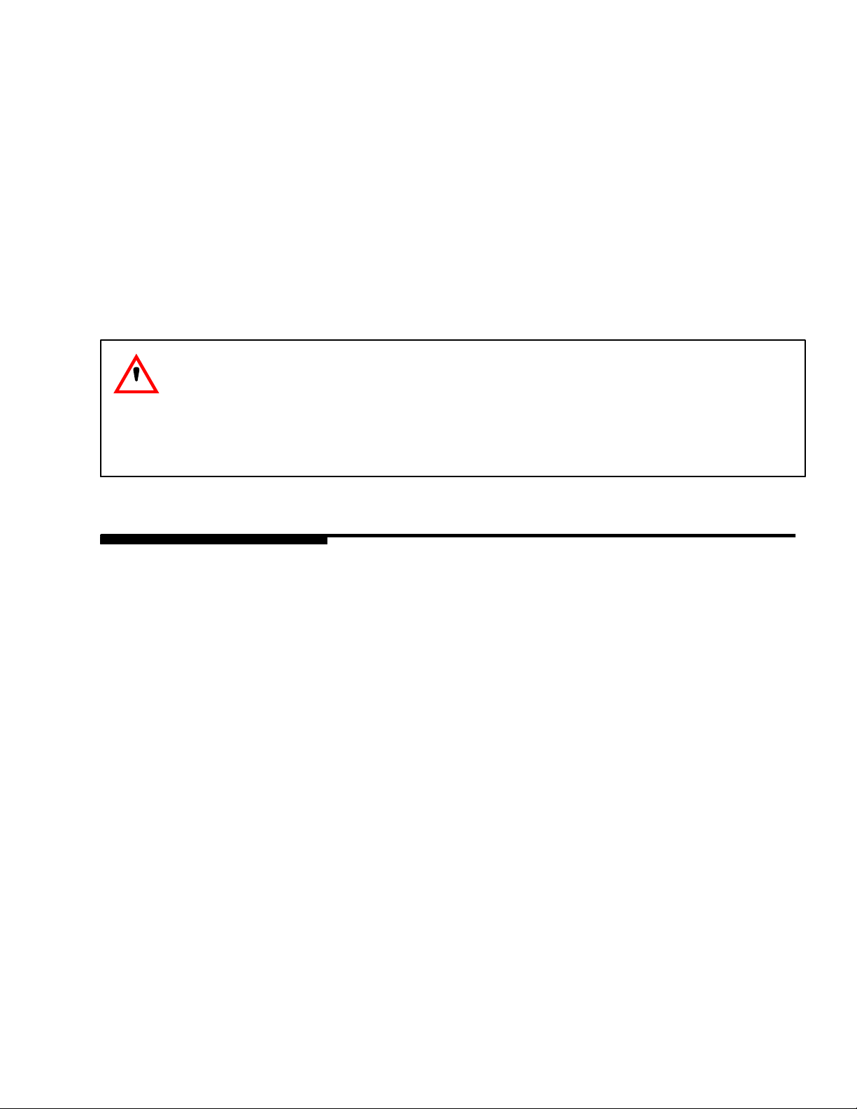
KIT 27065
NOTE: For dispensing Scotsman MH 750 ”nugget” style ice and Wilshire MCC550 and MCC700 compressed
ice cubes:
1. Disconnect power to dispenser.
2. Remove upper front panel from dispenser.
3. Remove ice chute and discard gate restrictor.
4. Install Ice Diverter as shown.
5. Reinstall front panel and energize
unit.
GATE MOUNTING PLATE
STORAGE HOPPER
10-32 WASHER
10-32 NUT
ICE CHUTE
ICE DIVERTER
GASKET
APPLY RTV TO THIS SURFACE
TO SEAL TO HOPPER GATE
MOUNTING PLATE
FLANGE EXTENDS INTO STORAGE
HOPPER THROUGH GATE OPENING
FIGURE 1. ICE DIVERTER
3 91748
Page 7
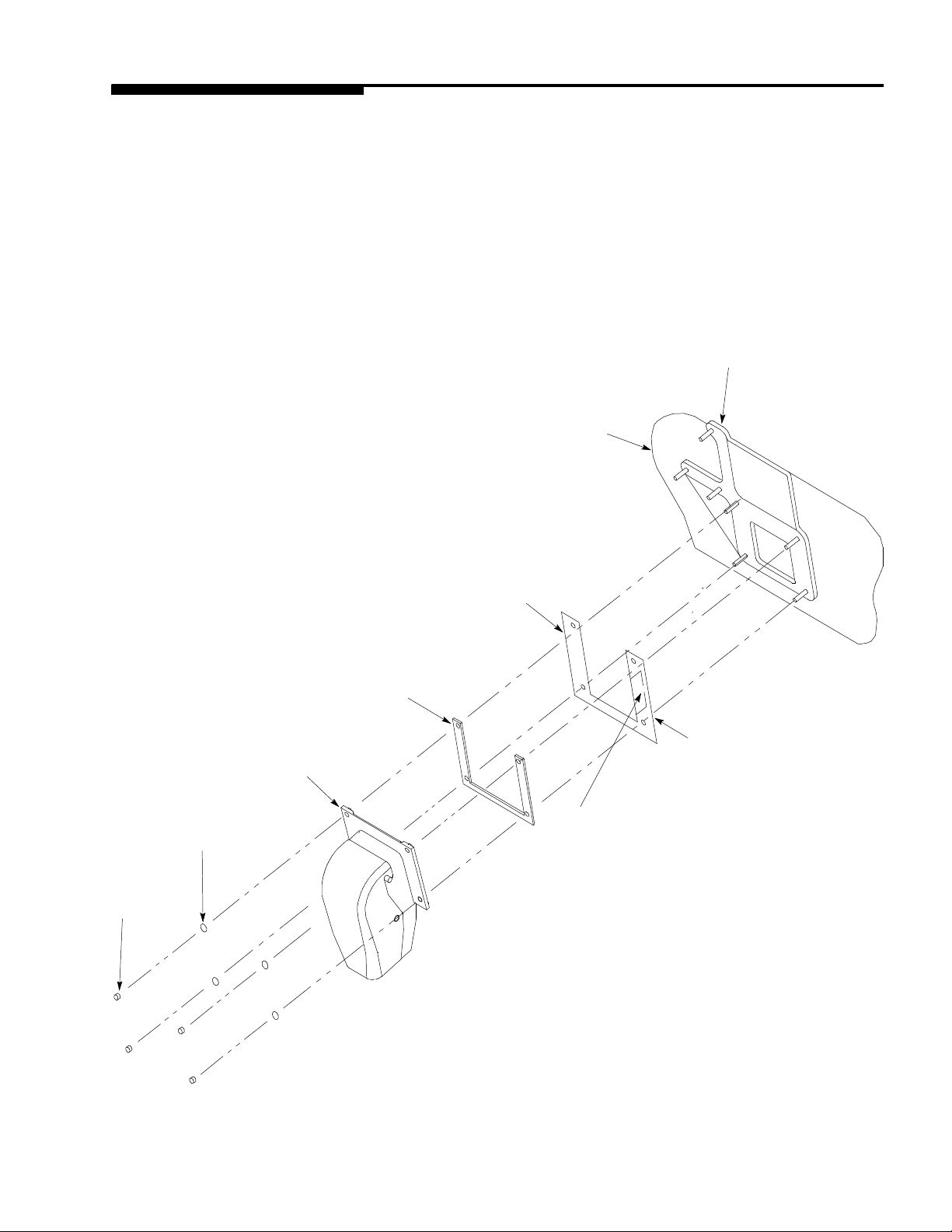
GATE RESTRICTOR PLATE
CAUTION: Disconnect power to dispenser before installing, removing or adjusting
restrictor.
FIGURE 2. GATE RESTRICTOR
ADJUSTMENT
This dispenser is provided with a gate restrictor plate, installed in its highest position. Th is plate adjusts the rate
of ice f lo w from the dispenser. In a ppl i cati on s using buckets, carafes or other large containers, th e plate may be
removed entirely for maximum ice f l ow. For glasses and cups, the plate may be adju sted downward to redu ce
the flow of ice. The best position depends on the type of ice being used and the size container and must be
found by trial and error. Adjustment is mad e by loosening the u pp er two ice chute retaining nuts, sliding the restrictor plat e to the desired po sition and re-tightenin g the nuts.
If the dispenser fails to dispense the ice whe n operate d, check that the hopper has ice in it a nd that power is
being supplied to the unit. If the problem persists, refer to the troubleshoot i n g guide (page 11).
491748
Page 8

22?
18-3/4?
1?
Opening in cabinet
4-1/2?
bottom for drain &
beverage hoses
Optional location for
counter top cut-out
14?
*1-1/8?3-15/16?
16-1/4?
*18-25/32?
29-3/4?
Front of Unit
*19-3/4?1-1/8?
NOTE: Leg mounting locations for ref (5/16--18 threads)
FIGURE 3. MOUNTING TEMPLATE
5 91748
Page 9

FIGURE 4. BEVERAGE SYSTEM PLUMBING DIAGRAM 6 VALVES
691748
Page 10

FIGURE 5. BEVERAGE SYSTEM PLUMBING DIAGRAM 4 VALVES
7 91748
Page 11

MAINTENANCE
The following dispenser maintenance should be performed at the intervals indicated:
DAILY (or as re quired)
Remove foreign material from vending area d rip tray to prevent drain blockage.
WEEKLY (or as required)
Clean vending are a. Check for proper water drainage from the vend in g area drip tray.
MONTHLY
Clean and sanitize the hopper interior (see CLEANING INSTRUCTIONS).
START--UP & OPERATING INSTRUCTIONS
Fill the hopper with ice. Dispense several large cups of ice (approxima tely 1 minute total dispensing time) t o allow
ice to f il l the cold plate. Add ice to the hop per as necessary to refill then replace t he lid. Allow 10 to 15 m in utes for
the cold plate t o cool down. Repeat this procedure whenever t he dispenser has bee n standing overnight or other
long periods without ice use. Start up the beverage system and adjust faucets to the proper brix. Contact your local syrup distributor for complet e informat i o n on the beverage system.
In normal operation, pushing the ice dispenser lever will cause ice to flow from the ice chute. Ice flow will continue
until the dispenser lever is released. Pushing the lever of any faucet will provide beverage of the appropriate flavor.
CAUTION: Use caution to avoid spilling ice when filling dispenser. Immediately clean up any
spilled ice from filling or operating the unit. To prevent contamination of ice, the lid must be
installed on the unit at all times.
CLEANING INSTRUCTIONS
WARNING: DISCONNECT POWER BEFORE CLEANING! Do not use metal scrapers, sharp
objects or abrasives on the ice storage hopper, top cover and the agitator disk, as damage
may result. Do not use solvents or other cleaning agents, as they may attack the plastic
material.
8 91748
Page 12

DISPENSER
1. Clean the ice storage hopper at least once a month
2. Remove the center screw on the agitator disk an d lift off the agitator and the agitator disk assembly. Wash
and rinse them thoroughly.
3. Washdown t h e inside of the h opp er a nd top cover with a mild detergent solution and rinse thoroughly to remove all traces of detergent.
4. Replace the agitator.
5. Sanitize the inside of the hopp e r and agitator with a solution of 1/2 ounce of household bleach in 1 gallon of
water. (200 PPM)
6. Replace the agitator disk. Sanitize as described is Step 5 . Be sure the center screw is replaced and the
screw is tight.
7. Remove Ice Chute Cover as follo ws:
A. Flex sides outward to disengage lower pins.
B. Lift Ice Chute cover to disengage upper pins.
C. Lower Ice Chu te cover down out of unit. NOTE: It may be helpful to twist cover slightly.
8. Clean the inside of the Ice Chute and Ice Chute cover with a mild detergent solution and rinse thoroughly to
remove all traces of detergent.
9. Reverse steps above to reassemble Ice Chute.
10. Sanitize as described in Step 5.
COLD PLATE
1. Remove splash panel a nd merchandiser.
2. Remove bottom two (2) screws on the ice chute and loosen the top two (2) screws. You do n ot have to remove the ice chute. (During re-assembly, make sure the ice gate restrictor is relocated to its’ correct position.
3. Remove the screws, hold the beverage faucet panel and bring forward.
4. Remove the tape holding the lower cold plate cover to the top cold plate cover.
5. Lift the lower cold plate cover up i n to t he top cover.
6. Remove any debris from the drain trough and spring. Check that the drain hole is not clogged.
7. Washdown t h e inside of the cold plate, tray and cover with a mild detergent solution and rinse. A small, long
handled brush will be found helpful in reaching the corners.
8. Slide the cover forward, t a king care that it is securely positioned on the cold plate.
9. Re-assemble.
9 91748
Page 13

BEVERAGE SYSTEMS
WARNING: If necessary to disassemble and clean dispensing valves’ syrup flow
regulators, do not intermix their pistons and cylinders as they are precision matched sets.
WARNING: To avoid possible personal injury or property damage, do not attempt to
remove syrup tank cover until CO2pressure has been released from tank.
WARNING: Ice bin contains hazardous moving parts. Ice rotator is automatically timed to
start and move a short distance to break up ice in ice bin. DO NOT remove ice bin cover
without first unplugging unit power cord from electrical outlet.
WARNING: Flush sanitizing solution from syrup systems as instructed. Residual sanitizing
solution left in system c ould create health hazard.
BEVERAGE SYSTEM CLEANING AND SANITIZING INSTRUCTIONS
1. Prepare the following cleaning, rinsing and sanit i zing solutions using a clean, empty figal (5 gallon syrup
tank) for each solution.
CLEANING TANK -- Fill with a solution of 1/2 ounce of a mild liquid detergent (for example, Ivory liquid) to 1
gallon of warm (120_F) potable water.
RINSING TANK -- Fill with warm (120 _F) potable water.
SANITIZING TANK -- Fill with a chlorine sanitizing solut io n in the strength of 1/2 ounce of household bleach
(sodium hypochlorite) to 1 gallon of cold (ambien t) pot ab le water to obtain a soluti o n strength of 200 PPM.
NOTE: Repeat the following procedure on each of the unit’s syrup product lines and beverage faucets.
2. Using a suitable pail or bucket, fill one wit h a detergent solution and a second container with a sanitizing
solution in the strengths as described in step 1.
A. Remove the syrup line qu ick disconnect fitting from the product tank and submerge in the detergent
solution. Clean wit h a nylon bristle brush (do not use a wire bru sh). Rinse with clean potable water.
B. Wearing sanitary glo ves, next submerge the quick disconnect fitting in the sanitizing container for 15
minutes. Remove and air dry.
3. Hook-up the sanitized product line fitting (step 2) to the cleaning tank. Hook-up a gas disconnect fitting to the
tank and pressurize with 60 t o 80 psig CO2. Energ ize the beverage faucet continuously for 1 m i n ute to remove all air bubbles. Continue to operate the faucet until liqui d dispensed is free of any syrup. Cycle the faucet for 15 seconds on, off and then im mediately on again. Repeat this procedure for 15 cycles. Then energize the faucet to remain flowing for 3 minutes.
4. Hook-up the rinsing tank and pressurize with 60 to 80 psig CO2. Flush the cleaning solution from the product
line by cycling the faucet as described in step 3 and energize the faucet to flow continuously for 3 minutes.
5. Hook-up the sanitizing t an k and pressurize with 60 to 80 psig CO2. Flow the san i tizing solution through the
beverage faucet by cyclin g the faucet as described in step 3. Next energize the faucet continuously to flush
at least 2 cups of the sanitizing solution through the system. Finally deenergize the faucet and allow the sanitizer to remain pressurized in the line to 20 minutes.
10 91748
Page 14

6. Wearing sanitary gloves. re move the faucet nozzle and diffuser. Repeat the cleaning and sanitizing procedures as described in step 2, then reassemble to the faucet.
7. Disconnect the sanitizing tank. Hook-up the produ ct tank to the unit and to the CO2system . Energize the faucet to flush the san i tizing solution from the syrup line and the faucet. Continue flow o n the faucet until only
syrup is dispensed.
11 91748
Page 15

TROUBLESHOOTING
IMPORTANT: Only qualified personnel should serviceinternal components of electrical wiring.
WARNING: Disconnect electrical power to unit before attempting any electrical repairs to
internal components. if repairs are to be made to CO2, syrup or plain water systems, shut off
plain water and CO2supplies then disconnect syrup tanks and bleed systems pressures
before proceeding.
Should your unit fail to operate properly, check that there is power to the unit and that the hopper contains ice. If the unit does not dispense, check the following chart under the appropriate symptoms to aid
in locating the defect.
Trouble Probable Cause
BLOWN FUSE OR CIRCUIT BREAKER. A. Short circuit in wiring.
B. Defective gate solenoid.
C. Defective agitator motor.
GATE DOES NOT OPEN. A. No power.
B. Bent d epressor plate (does not actuate switch).
C. Defective dispensing switch.
D. Blown/defective fuse or jammed gate solenoid.
GATE DOES NOT OPEN OR IS SLUGGISH.
AGITATOR TURNS.
GATE OPENS. AGIT ATOR DOES NOT TURN A. Ice solidified in hopper.
ICE DISPENSES CONTINUOUSLY. A. Stuck or bent depressor plate (does not
SLUSHY ICE. WATER IN HOPPER. A. Blocked drain.
A. Defective gate solenoid.
B. Excessive pressure against gate slide.
C. Weak gate spring .
B. Defective agitator motor.
C. Defective capacitor.
D. Defective agitation timer.
release switch).
B. Defective dispensing switch.
C. Improper switch installat io n.
B. Unit not level.
C. Poor ice quality due to water quality or
icemaker problems.
D. Improper use of fla ked ice.
1291748
Page 16

Contact your local soft drink or beverage equipment distributor for additional information and
troubleshooting of beverage system.
Trouble Probable Cause Remedy
NO PRODUCT DISPENSED A. Product ta nk quick disconnects
A. Connect q uick disconnects.
not properly connected.
B. No product supply (product
tank empty).
B. Replenish product supply as
instructed.
C. No CO2supply. C. Replenish CO2supply as
instructed.
DISPENSED PRODUCT
COMES OUT OF DISPENSING
A. Oil film or soap scum in glass
or cup.
A. Use clean cups and glasses.
VALVECL EAR BUT FOAMS IN
CUP OR GLASS.
B. Ice used for finished drink is
sub-cooled.
B. Do not use ice directly from
freezer. Allow ice to become “wet”
before using. Refer to NOTE.
NOTE: Ice also causes dispensing problem. When finished drink hits sharp edges of ice, carbonation
is released from drink.
DISPENSING PRODUCT
FOAMS AS IT LEAVES
DISPENSING VALVE.
A. Product ta nk CO2regulator
adjusted too high.
A. Adjust product tank CO2regulator
to pro per e quilibrium pressure as
instructed, then repl a ce product
supply.
B. Dispensing valvere stricted or
dirty.
B. Sanitize product system as
instructed.
C. Tube -- swivel nut
overtightened, distorting nylon
C. Replace nylon washer. Make sure
it is properly seated.
set washer inside -- resulting in
restricted product flow.
D. Oil, water or dirt in CO2supply. D. Remove contaminated CO
Clean CO2system (lines,
regulator etc.). Instal l clean CO
supply.
2.
2
13 91748
Page 17

ADJUST TO 7/8-IN. AS SHOWN
WHEN REPLACING SOLENOID,
BEFORE TIGHTENING MOUNTING SCREWS.
FIGURE 6. WIRING DIAGRAM BEV/CP DISPENSER
1491748
Page 18

34
33
15
17
5
32
31
6
30
17
1
2
12
16
11
14
13
4
10
7
8
18
19
25
3
9
29
28
20
21
22
23
FIGURE 7. DISPENSER SECTION EXPLODED VIEW
15 91748
Page 19

DISPENSER SECTION PARTS LIST
Index
No.
1 91498 Wiring Diagram
2 91546 Ice Gate Restrictor Instructions
3 70439 Leg, 4”
4 70855 Sink Grill
5 52030 Sink
6 52028 Lid
7 31163 Switch Boot Adapter
8 31007 Switch Boot
9 30895 Dispenser Switch
10 70847 Switch Spacer
11 215150 Depressor, Cup Activated
12 22644 Depressor Retainer (for 21515)
13 27126 Depressor Push Lever
14 27107 Depressor Retainer (for 27136)_
15 52026* Merchandiser Frame
16 27638 Splash Panel
17 10145 Sink Mtg. Pin
18 70545 Clamp
19 51775 Flexible Drain Fitting
20 51801 Cold Plate Drain Insulation
21 52049 Drain Insulation
22 27470 Mounting Bracket
23 52037 Plastic Drain Fitting
24 52044 O-Ring (2 required)
25 50997 Syrup. Fitting
26 51280 90° Fitting
27 50249 Armaflex, 1/2 ID x 3/8 W x 72”
28 50279 Armaflex, 1-1/8 ID x 3/8 W x 72”
29 28035 Beverage Panel 4 Valve
30 51455 Rear Cover Plate
31 27363 Lower Mounting Bracket
32 27345 Upper Mounting Bracket
33 Graphics Calls Parts Dept.
34 51996* Plexiglass Panel
Part No. Description
28996** Panel, S/S Merchandiser
28036 Beverage Panel, 6 Valve
* For Models 2230C4 and 2230C6
** For Models 2230C4-100 and 2230C6-100
1691748
Page 20

13
14
2
4
5
3
6
16
8
19
17
7
11
10
9
12
1,18
20
FIGURE 8. CABINET SECTION EXPLODED VIEW & PART LIST
Item
No. Part No. Description
1 30794 Agitator Motor Heater
2 31406 Fuse, 1-1/4 Amp
70438 Rebuild Kit
31551 Solenoid Service Kit
3 31093 Solenoid Assembly
4 31763 Agitator Timer
5 30774 Capacitor
6 51891 Gate Gasket
7 53015 Ice Chute Back Section
8 53016 Ice Chute Cover
9 50842 Motor Plate Insulation
10 51860 Motor Gasket
11 51859 Motor Shaft Seal
12 32498 Agitator Motor
13 51916 Agitator Disk
14 26591* Agitator
15 29026** Agitator
16 23062 Foam Shield
17 214910 Gate Slide
18 70341 Heater Spring
19 70260 1/4-20 x 1” Phil Rd Hd Screw
20 70815 1/4-20 Hex Motor Mounting Screw
* For Models 2230C4 and 2230C6
** For Models 2230C4-100 and 2230C6-100
17 91748
Page 21

FIGURE 9. SOLENOID ASSEMBLY
Index
No.
1 21493 1 Solenoid Mounting Plate
2# 31551 1 Solenoid Service Kit
3 70171 2 8--32 x 3/8 Phil Tr HD Screw
4 70121 2 No. 8 Lockwasher
5 50752 3 Isolator
6* 50789 2 Bumper Assembly
7* 70423 1 Cotter Pin
8* 10080 1 Gate Lift Rod
9 10081 1 Gate Lift Rod Bushing
10 50754 1 Gate Arm Bearing
11 21492 1 Gate lift Arm
12 70043 1 Flatwasher
13* 70422 1 Spring
14 70263 1 1/4-20 x 3/4 Hex Hd Screw
15 70048 1 1/4 Lockwasher
16 70066 1 1/4 Flatwasher
17 10077 1 Pivot Bearing
18 30227 1 1/4 Quick Connect T ab
19 50305 ---- Lubricant
20* 21592 1 Solenoid Linkage Pin
21* 70433 2 Retainer Ring
22 51088 ---- Loctite
----* 70438 ---- Rebuilding Kit
Part No. Quantity Description
NOTE: * Parts supplied with rebuilding kit.
# 31551 solenoid supplied with items 20 & 21.
1891748
Page 22

IMI CORNELIUS INC.
ONE CORNELIUS PLACE
ANOKA, MN. 55303- - 6234
TELEPHONE (800) 238--3600
FACSIMI LE (612) 422--3232
TECH SVC 1-800-535-4240
WARRANTY
IMI Cornelius Inc. and Remcor Products Company warrants that all equipment and parts are free from defects
in material and workmanship under normal use and service. For a copy of the warranty applicable to your
Cornelius and or Remcor product, in your country, please write, fax or telephone the IMI Cornelius office nearest you. Please provide the equipment model number,serial number and the date of purchase.
IMI Cornelius Offices
AUSTRALIA D P.O. 210, D R IVERWOOD, D NSW 2210, AUSTRALIA D (61) 2 533 3 122 D FAX (61) 2 534 2166
AUSTRIA D AM LANGEN FELDE 32 D A-1222 D VIENNA, AUSTRIA D (43) 1 233 520 D FAX (4 3) 1-23 35-2930
BELGIUM D BOSKAPELLEI 122 D B-293 0 BRAASCHAA T, BELGIUM D (32) 3 664 0552 D FAX (32) 3 665 23 07
BRAZIL D RUA ITAOCARA 97 D TOMAS COELHO D RIO DE JANEIRO, BRAZIL D (55) 21 591 7150 D FAX (55) 21 5 93 1 829
ENGLAND D TYTHING ROAD ALCESTER D WARWICKSHIRE, B49 6 EU, ENGLAND D (44) 789 763 10 1 D FAX (44) 789 7 63 6 44
FRANCE D 71 ROUTE DE ST.DENIS D F-95170 DEUIL LA BARRE D PARIS, FRANCE D (33) 1 3 4 28 6200 D FAX (33) 1 34 28 6201
GERMANY D CARL LEVERKUS STRASSE 15 D D-401 8 LANGENFELD, GERMANY D (49) 2 173 7930 D FAX (49) 2173 77 438
GREECE D 488 MESSOGION AVENUE D AGIA PARASKEVI D 153 42 D ATHENS, GREECE D (30) 1 600 1073 D FAX (3 0) 1 601 2491
HONG KONG D 1104 TAIKOTSUI CENTRE D 11-15 KOK CHEUNG ST D TAIKOKTSUE, HONG KONG D (852) 789 9882 D FAX (852 ) 391 622 2
ITALY D VIA PELLIZZARI 11 D 1-20059 D VIMARCATE, ITALY D (39) 39 6 08 0817 D FAX (39) 39 608 0814
NEW ZEALAND D 20 LANSFORD C RES. D P.O.BOX 19-044 AVONDALE D AUCKLAND 7, NEW ZEALAND D (64) 9 8 200 357 D FAX (64) 9 8200 361
SINGAPORE D 16 TUAS STREET D SINGAPORE 2263 D (65) 862 5542 D FAX (6 5) 862 56 04
SPAIN D POLIGONO INDUSTRAIL D RIERA DEL FONOLLAR D E-08830 SANT BOI DE LLOBREGAT D BARCELONA, SPAIN D (34) 3 640 2839 D FAX (34) 3 65 4 33 79
USA D ONE CORNELIUS PLACE D ANOKA, MINNESOTA D (612) 421-6120 D FAX (612) 422-3255
91748
19
Page 23

IMI CORNELIUS INC.
Corporate Headquarters:
Anoka, Minnesota 55303-6234
One Cornelius Place
(612) 421-6120
(800) 238-3600
 Loading...