

Page 1

JOCKEY III
Master Edition
Bedienungsanleitung
ACHTUNG!
Lesen Sie sich vor der ersten Inbetriebnahme zur eigenen Sicherheit diese
Bedienungsanleitung sorgfältig durch! Alle Personen, die mit der Aufstellung, Inbetriebnahme, Bedienung, Wartung und Instandhaltung dieses Gerätes zu tun haben, müssen entsprechend qualiziert sein und diese Betriebsanleitung genau beachten. Dieses Produkt erfüllt die Anforderungen der
geltenden europäischen und nationalen Richtlinien, die Konformität wurde
nachgewiesen, die entsprechenden Erklärungen und Unterlagen sind beim
Hersteller hinterlegt.
Instruction Manual
CAUTION!
For your own safety, please read this operation manual carefully before initial operation! All persons involved in the installation, setting-up, operation,
maintenance and service of this device must be appropriately qualied and
observe this operation manual in detail. This product complies with the requirements of the applicable European and national regulations. Conformity has
been proven. The respective statements and documents are deposited at the
manufacturer.
Professioneller 4-Deck-MIDI-Controller mit
integriertem 4-Kanal-Audio-Interface
Professional 4 deck MIDI controller with
integrated 4 channel soundcard
Contrôleur MIDI professionnel à 4 platines
avec interface audio 4 canaux intégrée
Mode d‘emploi
ATTENTION!
Pour votre propre sécurité, veuillez lire attentivement ce mode d‘emploi
avant la première utilisation ! Toutes les personnes chargées de l‘installation,
de la mise en service, de l‘utilisation, de l‘entretien et la maintenance de
cet appareil doivent posséder les qualications nécessaires et respecter les
instructions de ce mode d‘emploi. Ce produit est conforme aux directives
européennes et nationales, la conformité a été certiée et les déclarations
et documents sont en possession du fabricant.
DEUTSCH ............................. 2-29
ENGLISH .............................31-59
FRANÇAIS .........................60-87
WARNUNG!
Um Feuer oder einen elektrischen Schock zu vermeiden, setzen Sie dieses Gerät nicht Wasser oder Flüssigkeiten aus! Öffnen Sie niemals das Gehäuse!
WARNING!
To prevent re or avoid an electric shock do not expose the device to water or uids!
Never open the housing!
ATTENTION !
An d‘éviter un incendie ou une décharge électrique, veillez à tenir cet appareil
à l‘écart des liquides et de l‘humidité ! N´ouvrez jamais le boîtier !
Für weiteren Gebrauch aufbewahren!
Keep information for further reference!
Gardez ces instructions pour des utilisations ultérieurs!
www.reloopdj.com
Reloop Trademark
Global Distribution GmbH
Schuckertstr. 28
48153 Muenster / Germany
© COPYRIGHT
Nachdruck verboten!
1
Page 2

DEUTSCH
BEDIENUNGSANLEITUNG
ACHTUNG!
Lesen Sie sich vor der ersten Inbetriebnahme zur eigenen Sicherheit diese Bedienungsanleitung
sorgfältig durch! Alle Personen, die mit der Aufstellung , Inbetriebnahme, Bedienung, Wartung
und Instandhaltung dieses Gerätes zu tun haben, müssen entsprechend qualiziert sein und diese
Betriebsanleitung genau beachten. Dieses Produkt erfüllt die Anforderungen der geltenden europäischen und nationalen Richtlinien, die Konformität wurde nachgewiesen, die entsprechenden
Erklärungen und Unterlagen sind beim Hersteller hinterlegt.
INHALTSVERZEICHNIS
1. Aufbau . . . . . . . . . . . . . . . . . . . . . . . . . . . . . . . . . . . . . . . 4
1.1. Bedienelemente. . . . . . . . . . . . . . . . . . . . . . . . . . . 4-5
1.2. Anschlüsse . . . . . . . . . . . . . . . . . . . . . . . . . . . . . . . 6-7
2. Inbetriebnahme . . . . . . . . . . . . . . . . . . . . . . . . . . . . . . . 7
3. Computer-Konguration . . . . . . . . . . . . . . . . . . . . . . . . 7
3.1. ASIO Treiber-Installation . . . . . . . . . . . . . . . . . . . 7-9
3.2. Traktor LE -Einrichtung. . . . . . . . . . . . . . . . . . . . . 9
3.2.1. Installation . . . . . . . . . . . . . . . . . . . . . . . . . . . . . . . 9
3.2.2. Konguration . . . . . . . . . . . . . . . . . . . . . . . . . . . . . 9-11
3.3. Traktor Pro-Konguration (gegebenenfalls). . . . 11
3.3.1. Audio-Setup . . . . . . . . . . . . . . . . . . . . . . . . . . . . . . 11
3.3.2.Mapping-Import (nur Traktor Pro) . . . . . . . . . . . . 12-13
4. Bedienung. . . . . . . . . . . . . . . . . . . . . . . . . . . . . . . . . . . . 14
4.1. Traktor-Funktionsbelegung. . . . . . . . . . . . . . . . . . 14-17
4.2. Routing-Funktionen . . . . . . . . . . . . . . . . . . . . . . . . 18
4.2.1. Mikrofon . . . . . . . . . . . . . . . . . . . . . . . . . . . . . . . . . 18-19
4.2.2. Inputs. . . . . . . . . . . . . . . . . . . . . . . . . . . . . . . . . . . . 19-21
4.3. 4.3.Analog-Mixing-Funktion. . . . . . . . . . . . . . . . . 21
4.4. Outputs . . . . . . . . . . . . . . . . . . . . . . . . . . . . . . . . . . 21
4.5. Master-Thru und CUE-Master-Thru . . . . . . . . . . . 21
5. Geräteeinstellungen und -tests . . . . . . . . . . . . . . . . . . 21
5.1. Menu zur Einstellung der Midi-Channel-. . . . . . . 21
Zuweisung und der Jog-Wheel-Auösung
5.1.1. MIDI-Channel-Zuweisung . . . . . . . . . . . . . . . . . . . 22
5.1.2. Jog Wheel-Auösung . . . . . . . . . . . . . . . . . . . . . . 22
5.2. LED-Funktionstest . . . . . . . . . . . . . . . . . . . . . . . . . 22
5.3. Auto-Setup . . . . . . . . . . . . . . . . . . . . . . . . . . . . . . . 23
5.4. Firmware-Versions-Überprüfung. . . . . . . . . . . . . 23
5.5. Jog-Drag . . . . . . . . . . . . . . . . . . . . . . . . . . . . . . . . . 23
5.6. Jog-Sensitivity . . . . . . . . . . . . . . . . . . . . . . . . . . . . 23
5.7. LED-Dimmer. . . . . . . . . . . . . . . . . . . . . . . . . . . . . . 23
6. Updates & Support . . . . . . . . . . . . . . . . . . . . . . . . . . . . 23
6.1 Firmware-Update . . . . . . . . . . . . . . . . . . . . . . . . . . 23-25
6.2. Treiber-Update . . . . . . . . . . . . . . . . . . . . . . . . . . . . 25
6.3. Mappings. . . . . . . . . . . . . . . . . . . . . . . . . . . . . . . . . 25
7. Anhang . . . . . . . . . . . . . . . . . . . . . . . . . . . . . . . . . . . . . . 25
7.1. Systemanforderungen Traktor LE . . . . . . . . . . . . 25
7.2. MIDI-Zuweisungstabelle . . . . . . . . . . . . . . . . . . . . 25-27
7.3. Tipps zur Fehlerbehebung . . . . . . . . . . . . . . . . . . 28
7.4. Technische Daten. . . . . . . . . . . . . . . . . . . . . . . . . . 29
2
Wir gratulieren Ihnen zum Kauf des Reloop Jockey 3 Master Edition. Vielen Dank, dass Sie unserer
Diskjockey-Technologie Ihr Vertrauen schenken. Vor Inbetriebnahme bitten wir Sie, alle Anweisungen sorgfältig zu studieren und zu befolgen.
Nehmen Sie den Reloop Jockey 3 Master Edition aus der Verpackung. Bitte überprüfen Sie vor der
ersten Inbetriebnahme, ob kein offensichtlicher Transportschaden vorliegt. Sollten Sie Schäden am
Stromkabel oder am Gehäuse entdecken, nehmen Sie das Gerät nicht in Betrieb und setzen Sie sich
bitte mit Ihrem Fachhändler in Verbindung.
Page 3

SICHERHEITSHINWEISE
ACHTUNG!
Seien Sie besonders vorsichtig beim Umgang mit der Netzspannung. Bei dieser Spannung können
Sie einen lebensgefährlichen elektrischen Schlag erhalten! Bei Schäden, die durch Nichtbeachtung dieser Bedienungsanleitung verursacht werden, erlischt jeder Gewährleistungsanspruch. Bei
Sach- oder Personenschäden, die durch unsachgemäße Handhabung oder Nichtbeachtung der Sicherheitshinweise verursacht werden, übernimmt der Hersteller keine Haftung.
- Dieses Gerät hat das Werk in einwandfreiem Zustand verlassen. Um diesen Zustand zu erhalten
und einen gefahrlosen Betrieb sicherzustellen, muss der Anwender unbedingt die Sicherheitshinweise und die Warnvermerke beachten, die in dieser Gebrauchsanleitung enthalten sind.
- Aus Sicherheits- und Zulassungsgründen (CE) ist das eigenmächtige Umbauen und/oder Verändern des Gerätes nicht gestattet. Beachten Sie bitte, dass Schäden, die durch manuelle Veränderungen an diesem Gerät verursacht werden, nicht unter den Gewährleistungsanspruch fallen.
- Im Geräteinneren benden sich keine zu wartenden Teile, ausgenommen die von außen austauschbaren Verschleißteile. Die Wartung darf nur von fachkundigem Personal durchgeführt werden, an-
sonsten verfällt die Gewährleistung!
- Die Sicherung darf nur gegen Sicherungen des gleichen Typs, der gleichen Auslösecharakteristik
und Nennstromstärke ausgetauscht werden.
- Stellen Sie sicher, dass die Stromversorgung erst nach dem Aufbau des Gerätes erfolgt. Den Netzstecker immer als letztes einstecken. Vergewissern Sie sich, dass der Netzschalter auf „OFF“
steht, wenn Sie das Gerät ans Netz anschließen.
- Benutzen Sie nur vorschriftsmäßige Kabel. Achten Sie darauf, dass alle Stecker und Buchsen fest
angeschraubt und richtig angeschlossen sind. Bei Fragen wenden Sie sich bitte an Ihren Händler.
- Stellen Sie sicher, dass beim Aufstellen des Produktes das Netzkabel nicht gequetscht oder durch
scharfe Kanten beschädigt wird.
- Lassen Sie das Netzkabel nicht mit anderen Kabeln in Kontakt kommen! Seien Sie vorsichtig beim
Umgang mit Netzkabeln und -anschlüssen. Fassen Sie diese Teile nie mit nassen Händen an!
-
Stecken Sie das Stromkabel nur in geeignete Schukosteckdosen ein. Als Spannungsquelle darf dabei
nur eine ordnungsgemäße Netzsteckdose des öffentlichen Versorgungsnetzes verwendet werden.
- Trennen Sie das Gerät bei Nichtbenutzung und vor jeder Reinigung vom Netz! Fassen Sie dazu den
Netzstecker an der Griffäche an und ziehen Sie niemals an der Netzleitung!
- Stellen Sie das Gerät auf einer horizontalen und stabilen, schwer entammbaren Unterlage auf.
- Vermeiden Sie Erschütterungen und jegliche Gewaltanwendung bei der Installation oder Inbetriebnahme des Gerätes.
- Achten Sie bei der Wahl des Installationsortes darauf, dass das Gerät nicht zu großer Hitze, Feuchtigkeit und Staub ausgesetzt wird. Vergewissern Sie sich, dass keine Kabel frei herumliegen. Sie
gefährden Ihre und die Sicherheit Dritter!
- Stellen Sie keine Flüssigkeitsbehälter, die leicht umfallen können, auf dem Gerät oder in dessen
Nähe ab. Falls doch einmal Flüssigkeit in das Geräteinnere gelangen sollte, sofort den Netzstecker
ziehen. Lassen Sie das Gerät von einem qualizierten Servicetechniker prüfen, bevor es erneut
genutzt wird. Beschädigungen, die durch Flüssigkeiten im Gerät hervorgerufen wurden, sind von
der Gewährleistung ausgeschlossen.
- Betreiben Sie das Gerät nicht in extrem heißen (über 35° C) oder extrem kalten (unter 5° C) Umgebungen. Halten Sie das Gerät von direktem Sonnenlicht und von Wärmequellen wie Heizkörpern,
Öfen, usw. (auch beim Transport in geschlossenen Wagen) fern. Verdecken Sie niemals vorhandene
Lüfter oder Lüftungsschlitze. Sorgen Sie immer für eine ausreichende Ventilation.
- Das Gerät darf nicht in Betrieb genommen werden, wenn es von einem kalten Raum in einen warmen Raum gebracht wurde. Das dabei entstehende Kondenswasser kann unter Umständen Ihr Ge-
rät zerstören. Lassen Sie das Gerät solange abgeschaltet, bis es Zimmertemperatur erreicht hat!
- Regler und Schalter sollten niemals mit Sprühreinigungsmitteln und Schmiermitteln behandelt
werden. Dieses Gerät sollte nur mit einem feuchten Tuch gereinigt werden, verwenden Sie niemals
Lösungsmittel oder Waschbenzin zum Reinigen.
- Bei Umzügen sollte das Gerät im ursprünglichen Versandkarton transportiert werden.
- Zu Beginn müssen die Überblendregler und Lautstärkeregler Ihres Verstärkers auf Minimum eingestellt und die Lautsprecherschalter in „OFF“-Position geschaltet sein. Vor dem Lauterstellen 8 bis
10 Sekunden warten, um den durch Einschwingung erzeugten Schroteffekt zu vermeiden, welcher
zu Lautsprecher- und Frequenzweichenschäden führen könnte.
- Geräte, die an Netzspannung betrieben werden, gehören nicht in Kinderhände. Lassen Sie deshalb
in Anwesenheit von Kindern besondere Vorsicht walten.
- In gewerblichen Einrichtungen sind die Unfallverhütungsvorschriften des Verbandes der gewerblichen Berufsgenossenschaft zu beachten.
DEUTSCH
3
Page 4

- In Schulen, Ausbildungseinrichtungen, Hobby- oder Selbsthilfewerkstätten ist das Betreiben des
Gerätes durch geschultes Personal verantwortlich zu überwachen.
- Heben Sie diese Bedienungsanleitung für spätere Fragen und Probleme gut auf.
BESTIMMUNGSGEMÄSSE VERWENDUNG
Bei diesem Gerät handelt es sich um einen professionellen DJ MIDI Controller mit integrierter 6-In /
4-Out Soundkarte, mit dem sich Software steuern lässt. Das Gerät wird dabei mit einem USB Kabel
am Computer angeschlossen.
Dieses Produkt ist für den Anschluss an 240 V, 50 Hz Wechselspannung über das beiliegende Ste-
ckernetzteil zugelassen und wurde ausschließlich zur Verwendung in Innenräumen konzipiert.
Wird das Gerät anders verwendet als in dieser Bedienungsanleitung beschrieben, kann dies zu Schäden am Produkt führen und der Gewährleistungsanspruch erlischt. Außerdem ist jede andere Verwendung mit Gefahren wie z.B. Kurzschluss, Brand, elektrischem Schlag, etc. verbunden.
Die vom Hersteller festgelegte Seriennummer darf niemals entfernt werden, da ansonsten der Gewährleistungsanspruch erlischt.
WARTUNG
- Überprüfen Sie regelmäßig die technische Sicherheit des Gerätes auf Beschädigungen des Netzkabels
oder des Gehäuses, sowie auf die Abnutzung von Verschleißteilen wie Dreh- und Schiebereglern.
- Wenn anzunehmen ist, dass ein gefahrloser Betrieb nicht mehr möglich ist, so ist das Gerät außer Be-
trieb zu setzten und gegen unbeabsichtigten Betrieb zu sichern. Netzstecker aus der Steckdose ziehen!
- Es ist anzunehmen, dass ein gefahrloser Betrieb nicht mehr möglich ist, wenn das Gerät sichtbare
Beschädigungen aufweist, das Gerät nicht mehr funktioniert, nach längerer Lagerung unter ungünstigen Verhältnissen oder nach schweren Transportbeanspruchungen.
DEUTSCH
1. AUFBAU
1.1. BEDIENELEMENTE
T29 T29
T41
T28
T37
T38
T39
T40
T42
T31
T32
T33
T34
T34
T14
T20
T15
T20
T16
T20
T7T4 T5 T6
T17
T20
T1 T1
T12 T12T13 T13
T18 T18T19 T19
T21 T21
T2 T2
T4
T8 T8
T14
T20
T3 T3T3 T3T3 T3
T30 T30
T5 T6
T9 T9
T15
T20
T10 T10T11 T11
T16
T20
T7
T17
T20
T31
T32
T33
T34
T34
4
T22
T23 T23
T27 T27T24 T24T25 T25T26 T26
T36 T36
T43
T44
T22
Page 5
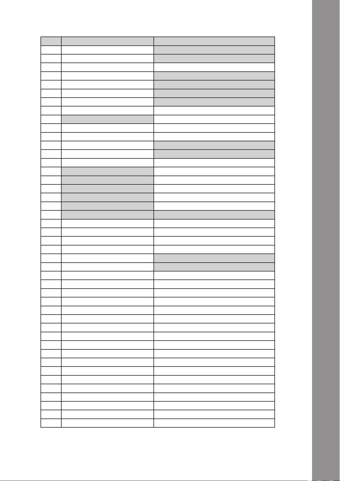
Geräteoberseite
# Bezeichnung Shift Bezeichnung
T01 Pitchfader Key
T02 Dry/Wet-Regler Effektwechsel im Advanced-Effekt-Modus
T03 Effektparameter Effektwechsel im Chained-Effekt-Modus
T04 FX On-Taste FX Preset 1
T05 Effekt-Reset bzw. FX 1 On FX Preset 2
T06 Effekt-Taste 1 bzw. FX 2 On FX Preset 3
T07 Effekt-Taste 2 bzw. FX 3 On FX Preset 4
T08 Loop-Länge
T09 Loop verschieben
T10 Filter
T11 Pan(Balance)-Regler
T12 Pitchbend-Taste – FX 1
T13 Pitchbend-Taste + FX 2
T14 Autoloop-Funktion Loop In/Set Cue-Taste
T15 Reloop-Funktion Loop Out-Taste
T16 Beatjump zurück linksläuge GRID-Verschiebung
T17 Beatjump vorwärts rechtsläuge GRID-Verschiebung
T18 Hot Cue-Lösch-Taste
T19 Hot Cue-Bankwahl
T20 Hot Cue-Tasten Sampleplayer 1 – 8
T21 Jog Wheel Modi-Tasten
T22 Jog Wheel
T23 Shift-Taste
T24 Synchronisierungs-Taste Deck Master Select
T25 Cup-Taste Beat Tab
T26 Cue-Taste FX Mode
T27 Play/Pause-Taste Keylock
T28 TRAX-Encoder Ordnernavigation
T29 Load-Taste Favoriten-Ordner-Navigation
T30 Deck-Auswahl-Schalter
T31 Gain-Regler
T32 EQ-Regler High
T33 EQ-Regler Mid
T34 EQ-Regler Low
T35 Monitor-CUE-Taste Preview-Player Load&Play bzw. Stopp
T36 Linefader
T37 Master-Lautstärke
T38 Booth-Lautstärke
T39 Kopfhörer-Lautstärke
T40 CUE-Mix-Überblendung
T41 Power-LED
T42 MIDI-Signal-LED
T43 VU-Meter
T44 Crossfader
DEUTSCH
5
Page 6
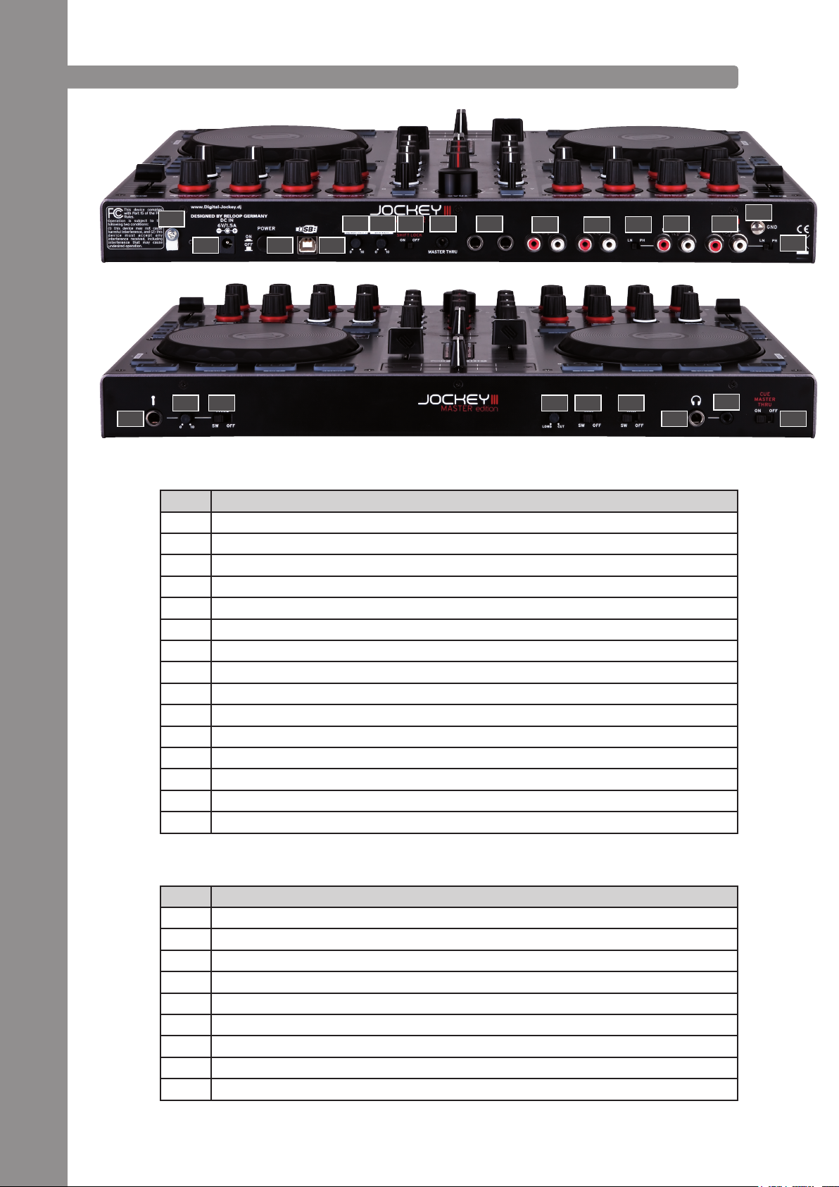
1.2. ANSCHLÜSSE
DEUTSCH
B54
F45
Geräterückseite
# Bezeichnung
B54 Netzkabel-Zugentlastung
B55 Netzteilanschluss (DC 6V/1,5A)
B56 Ein/Aus-Schalter
B57 USB-Anschluss
B58 Jog-Wheel-Sensitivity
B59 LED-Dimmer
B60 Shift-Lock Schalter
B61 3,5 mm Klinke Master-Thru Eingang
B62 6,3 mm Klinke Master 2 Audio-Ausgang (balanced)
B63 Cinch Master 1 Audio-Ausgang
B64 Cinch Booth Audio-Ausgang
B65 Line/Phono Umschalter
B66 Cinch-Input 2
B67 Cinch-Input 1
B68 Erdungsschraube
F46 F47
B65
B62B61B60B59B58
B57B56B55
B63
B64
F48 F49 F50
B65
B66
F51
B67
B65
F52
F53
Gerätevorderseite
# Bezeichnung
F45 6,3 mm Klinke Mikrofonanschluss
F46 Mikrofon-Lautstärke
F47 Mikrofon-Routing-Schalter
F48 Crossfader-Curve
F49 Input 1 Routing-Schalter
F50 Input 2 Routing
F51 6,3 mm Klinke Kopfhöreranschluss
F52 3,5 mm Klinke Kopfhöreranschluss
F53 Master-Thru-Routing-Schalter
6
Page 7
Geräteseite
# Bezeichnung
S69 Jog Wheel-Widerstand
S70 Kensington-Lock
2. INBETRIEBNAHME
- Schalten Sie das Gerät zunächst über den Ein/Aus-Schalter -B56- auf der Rückseite aus.
- Verbinden Sie das beiliegende Netzteil mit der DC-Buchse -B55- des Gerätes. Stecken Sie nun den
Netzadapter in eine freie Steckdose.
- Verbinden Sie anschließend das mitgelieferte USB-Kabel mit dem Anschluss -B57- auf der Rückseite des Gerätes und einer freien USB-Schnittstelle an Ihrem Computer.
3. COMPUTER-KONFIGURATION
Bevor Sie mit Ihrem neuen Gerät loslegen können, müssen noch einige grundlegende Einstellungen
an Ihrem Computer-System vorgenommen werden.
ACHTUNG!
Bitte vergewissern Sie sich, dass Reloop Jockey 3 sich noch im ausgeschalteten Zustand bendet. Erst während der Installation werden Sie dazu aufgefordert, diesen einzuschalten.
Das beiliegende USB-Kabel darf bereits angeschlossen sein.
Bitte schenken Sie den folgenden Punkten genaue Beachtung.
3.1. ASIO TREIBER-INSTALLATION
Legen Sie die mitgelieferte Installations-CD in Ihr Laufwerk. Im Ordner „Drivers“ wählen Sie den für
Ihr System passenden Treiber aus und starten die Installation mit einem Doppelklick.
TIPP!
Reloop stellt stets aktualisierte Treiber online zur Verfügung. Für mehr Informationen lesen Sie
bitte das Kapitel „Updates & Support“.
HINWEIS!
Bitte stellen Sie sicher, dass Sie die Treiber-Installation mit Administratorrechten starten. Ansonsten wird die Installation mit einer Fehlermeldung scheitern.
Verwenden Sie Windows Vista bzw. Windows 7, so führen Sie das passende Installations-Setup mit
einem Rechtsklick und anschließender Auswahl „Als Administrator ausführen“ aus.
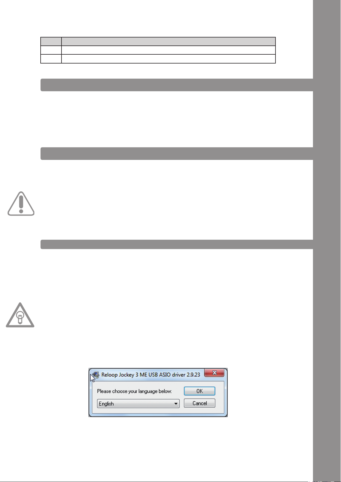
1. Sie kommen als erstes ins Sprachen-Auswahlfenster. Bitte wählen Sie Ihre bevorzugte Sprache aus.
DEUTSCH
7
Page 8
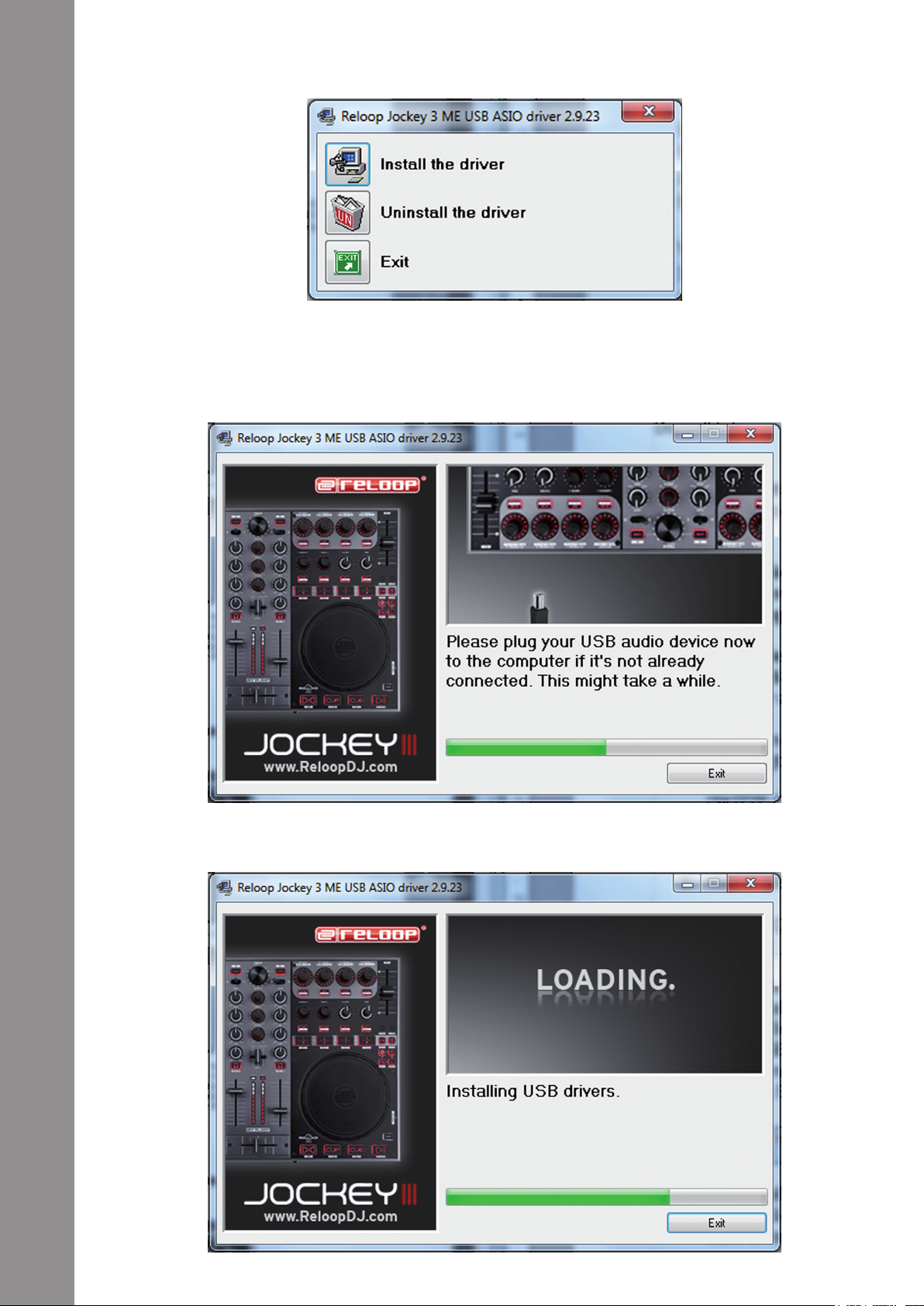
2. Klicken Sie nun auf die Schaltäche „Treiber installieren“.
3. Sie werden anschließend aufgefordert, Reloop Jockey 3 anzustecken und einzuschalten. Sollte
Reloop Jockey 3 noch nicht per USB verbunden sein, so schließen Sie das mitgelieferte USB-
Kabel am USB-Port -B57- und an einem freien USB-Anschluss Ihres Computers an. Verbinden Sie
ebenfalls das mitgelieferte Netzteil mit dem Netzteilanschluss -B55-.
Schalten Sie nun das Gerät über den Ein/Aus-Schalter -B56- ein.
DEUTSCH
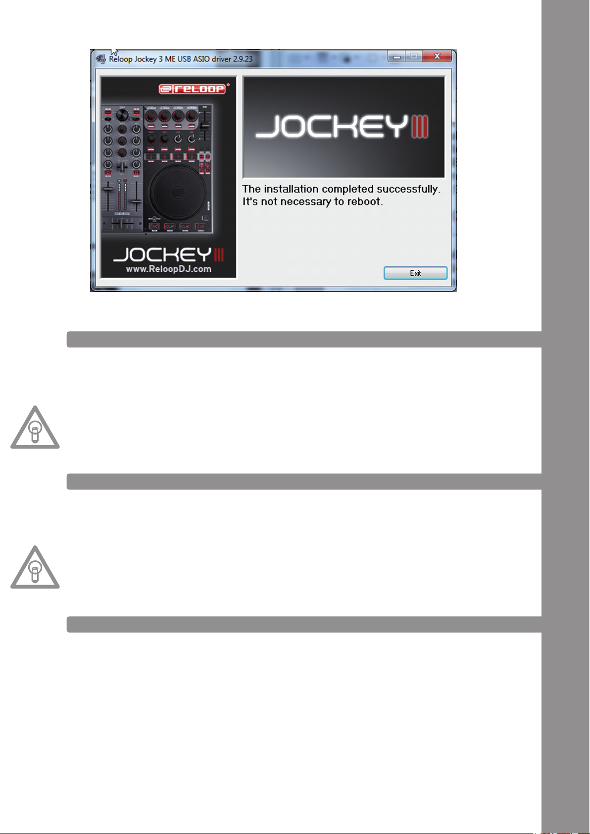
4. Die Installation wird fortgesetzt. Wenn die Installation erfolgreich beendet wurde, können Sie das
Setup über die Schaltäche „Beenden“ schließen. Ein Neustart ist nicht erforderlich.
8
Page 9
3.2. TRAKTOR LE-EINRICHTUNG
Mit Reloop Jockey 3 erhalten Sie die kostenlose und uneingeschränkt verwendbare DJ-Software
„Traktor LE“.
HINWEIS!
Upgrade auf Traktor Pro (4 Deck-Unterstützung):
Mit Ihrer beiliegenden Traktor LE Version haben Sie den Vorteil, die umfangreiche Traktor PRO
Version zum Vorzugspreis zu erwerben. Aktuelle Preiskonditionen erfahren Sie auf www.nativeinstruments.de
3.2.1. INSTALLATION
Auf der beiliegenden Installations-CD nden Sie neben den ASIO-Treibern das Verzeichnis „Traktor“.
Öffnen Sie dieses und wählen Sie die für Ihr System passende Setup-Datei aus.
Befolgen Sie die Anweisungen im Installationsfenster.
HINWEIS!
Details zu den Systemanforderungen nden Sie im Punkt „Systemanforderungen Traktor LE“ des
Anhangs.
DEUTSCH
3.2.2. KONFIGURATION
Wird Traktor LE das erste Mal verwendet, so sollte der „Setup Wizard“ starten. Ist dies nicht der Fall,
so klicken Sie auf „Help“ und wählen den Menüpunkt „Start Setup Wizard“.
Im Setup Wizard wählen Sie folgende Punkte aus:
1. Die erste Frage „Are you using a USB/FireWire controller?“ beantworten Sie mit „Yes“. Anschlie-
ßend klicken Sie auf „Next“.
2. Im Bereich „Choose your manufacturer:“ wählen Sie den Eintrag „Reloop“. Die anschließende
Auswahlmöglichkeit „Choose your model:“ beantworten Sie mit „ Jockey 3 ME“. Wiederum be-
stätigen Sie die Auswahl mit „Next“.
3. Die folgenden Fragen bezüglich angeschlossener Hardware des Herstellers „Native Instruments“
beantworten Sie standardmäßig mit „No“.
Ihr Reloop Jockey 3 sollte nun entsprechend für Traktor LE konguriert sein.
9
Page 10
HINWEIS!
Standardmäßig sollte das Audio-Setup auf den Internal-Mixing-Modus eingestellt sein.
Sollte dies nicht der Fall sein, so beachten Sie die folgenden Punkte genau.
Ansonsten können Sie dieses Kapitel überspringen und beim Kapitel „Bedienung“ fortsetzen.
Audio Setup
Internal-Mixing-Modus
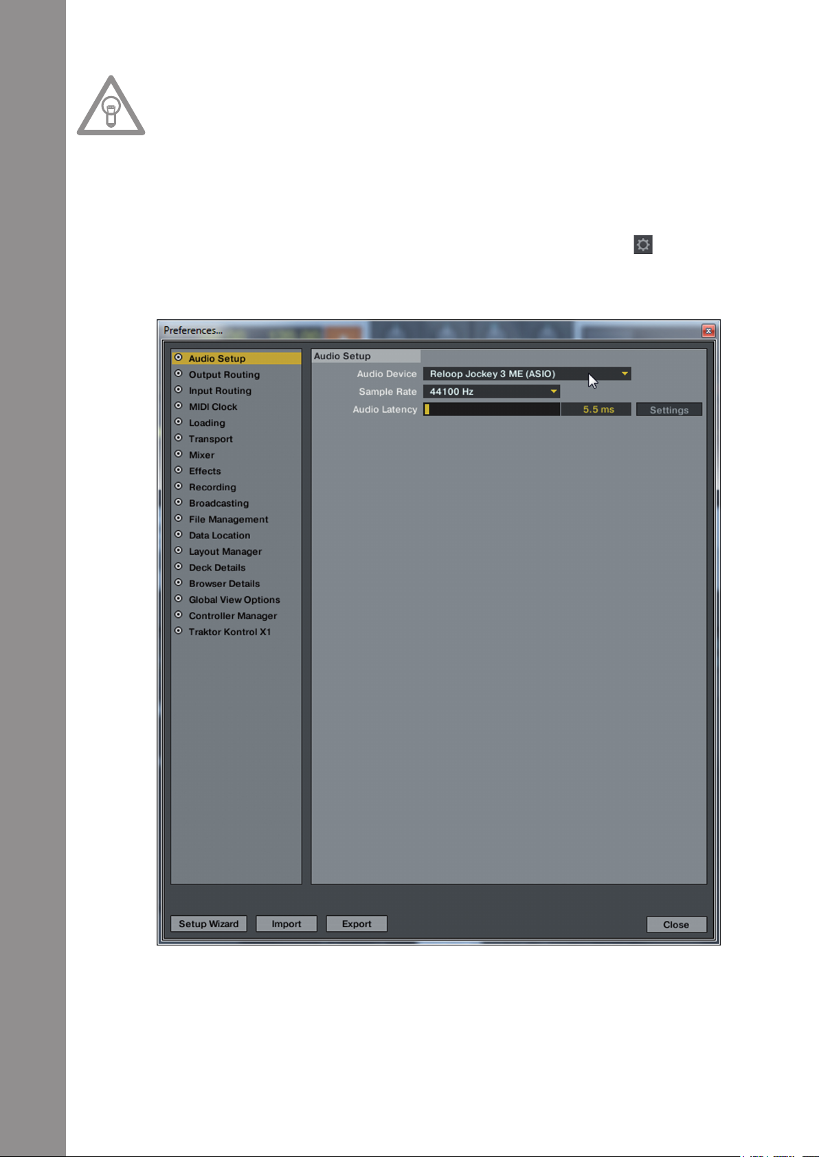
1. Öffnen Sie in Traktor den Einstellungsdialog, indem Sie auf das kleine Zahnrad am oberen,
rechten Rand klicken.
2. Öffnen Sie die Kategorie „Audio Setup“ und wählen im Bereich „Audio Device“ den Eintrag „Re-
loop Jockey 3 (ASIO)“.
DEUTSCH
10
Page 11

3. Öffnen Sie nun die Kategorie „Output Routing“ und wählen im Bereich „Mixing Mode“ die Schalt-
äche „Internal“. Die Kanalzuweisung entnehmen Sie bitte folgendem Beispiel:
3.3. TRAKTOR PRO-KONFIGURATION [GEGEBENENFALLS]
Sollten Sie bereits Traktor Pro besitzen oder kostengünstig von der beiliegenden Traktor LE-Version
upgegradet haben, so können alle Funktionen von Jockey 3 voll ausgeschöpft werden.
Damit Traktor mit Ihrem Setup im Zusammenhang mit Jockey 3 zusammenspielt, gehen Sie folgende Punkte genau durch.
DEUTSCH
3.3.1. AUDIO-SETUP
Das Audio-Setup unterscheidet sich nicht vom Traktor LE Audio-Setup. Bitte verfahren Sie wie im
Punkt 3.2.2. beschrieben.
11
Page 12
3.3.2. MAPPING-IMPORT
Damit Traktor die MIDI-Befehle, die vom Jockey 3 gesendet werden, den richtigen Funktionen zuord-
nen kann, ist eine Befehlszuweisungstabelle, auch Mapping genannt, nötig.
Eine passende Mapping-Datei nden Sie auf der Installations-CD im Ordner „Mappings/Traktor Pro“.
HINWEIS!
Stets aktualisierte und erweiterte Mappings nden Sie auch online. Surfen Sie dazu auf http://
www.reloopdj.com/forum und öffnen Sie die Kategorie „Mapping les“ im Bereich „Downloads for
all Reloop products“.
Bitte befolgen Sie folgende Schritte, um das Mapping zu importieren:
1. Öffnen Sie in Traktor den Einstellungsdialog, indem Sie auf das kleine Zahnrad am oberen,
rechten Rand klicken.
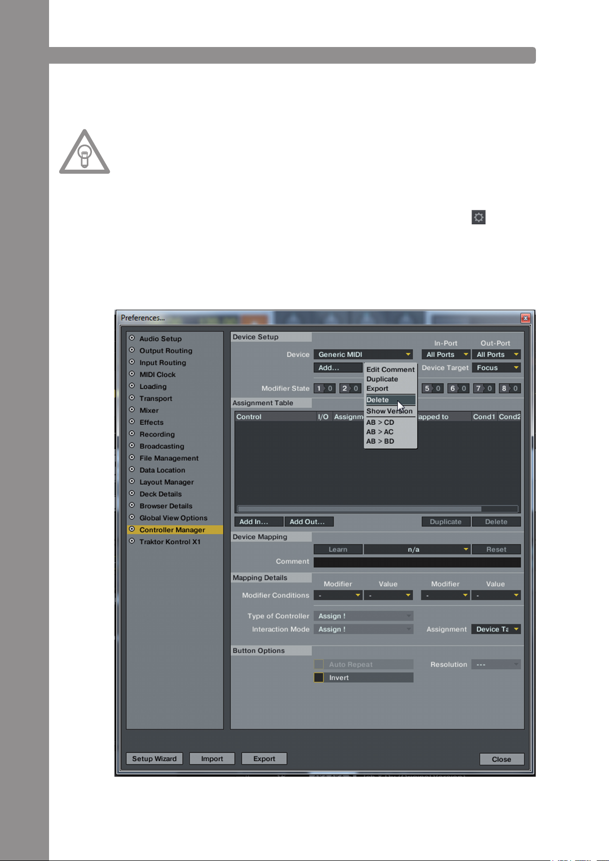
2. Öffnen Sie die Kategorie „Controller Manager“.
3. Um Probleme zu vermeiden, wird empfohlen, alle existierenden Einträge mit Ausnahme des Key-
board-Mappings aus dem Controller-Manager zu löschen:
Wählen Sie dazu im Bereich „Device“ nacheinander jeden Eintrag aus, drücken „EDIT...“,
anschließend „Delete“.
DEUTSCH
12
Page 13
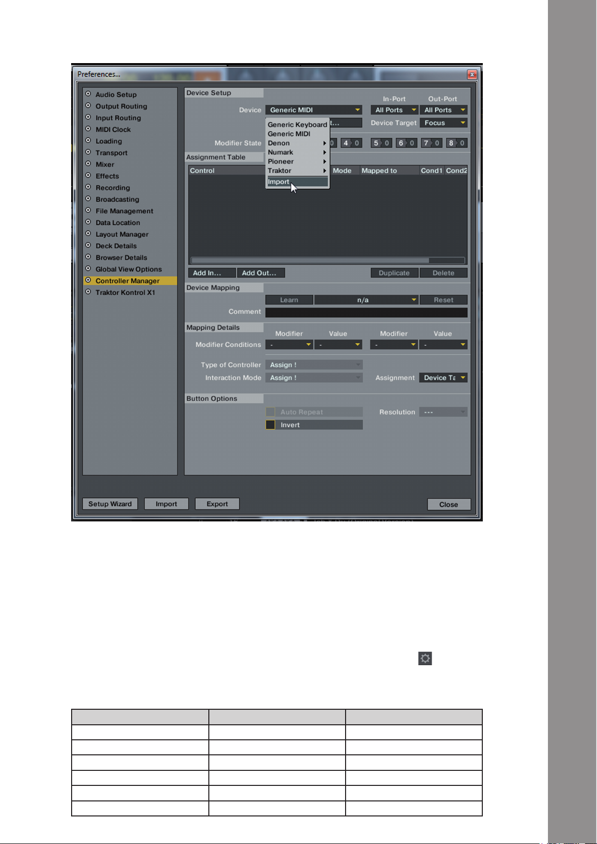
4. Betätigen Sie nun die Schaltäche „Add...“ und wählen „Import“.
Im Auswahlfenster öffnen Sie die Mapping-Datei, die sich auf der CD bendet oder gerade von der
Reloop-Supportseite heruntergeladen wurde.
Problembehebung
Sollte ein Problem auftauchen, wobei die LEDs des Jockey 3 nicht ordnungsgemäß aueuchten, so
liegt es in den meisten Fällen an installierter MIDI-Software (z.B. MidiYoke, Maple Virtual MIDI cable,
OSCulator, Bome Midi-Translator, etc.).
DEUTSCH
Zur Behebung des Problems wie folgt vorgehen:
1. Öffnen Sie in Traktor den Einstellungsdialog, indem Sie auf das kleine Zahnrad am oberen,
rechten Rand klicken.
2. Öffnen Sie die Kategorie „Controller Manager“.
3. Für die folgenden Device-Einträge müssen folgende Port-Zuweisungen konguriert werden:
Device In-Port Out-Port
Jockey 3 V* (Deck A) Reloop Jockey 3 Reloop Jockey 3
Jockey 3 V* (Deck B) Reloop Jockey 3 Reloop Jockey 3
Jockey 3 V* (Deck C) Reloop Jockey 3 Reloop Jockey 3
Jockey 3 V* (Deck D) Reloop Jockey 3 Reloop Jockey 3
Jockey 3 V* (Mixer) Reloop Jockey 3 Reloop Jockey 3
Jockey 3 V* (FX Presets) Reloop Jockey 3 Reloop Jockey 3
13
Page 14
4. BEDIENUNG
Nachdem der Reloop Jockey 3 angeschlossen und richtig in der DJ-Software Traktor konguriert
wurde, kann diese nun bedient werden. Wird Traktor Pro verwendet, so kann die Jockey 3 Bedienober-
äche voll ausgeschöpft werden. Für Traktor LE ergeben sich, insbesondere für die Effektsteuerung,
die Anzahl der verwendbaren Decks und die Hot Cue-Belegung einige Unterschiede.
4.1. TRAKTOR-FUNKTIONSBELEGUNG
HINWEIS!
Im Folgenden wird die gesamte Traktor-Funktionsbelegung beschrieben. Einige Features sind nur
in Traktor Pro möglich und sind daher in der folgenden Tabelle grau markiert.
Element Funktion Funktion bei aktivem Shift -T3-
T1 Pitchfader
Hiermit wird der Pitch auf dem aktuellen Deck
(siehe -T30-) eingestellt.
T2 Dry/Wet-Regler
Mit dem Encoder lässt sich die Effektstärke
einstellen.
T3 Effektparameter <Advanced E.>
Im Advanced Effekt-Modus lassen sich hiermit
die Parameter justieren.
Dry/Wet-Feinregelung <Chained E.>
Wird der Chained Effekt-Modus verwendet, so
lassen sich die einzelnen Effekte mit den Encodern steuern.
HINWEIS!
In Traktor LE funktioniert nur der 1. Parameter
im Chained Effekt-Modus.
Keyfader
Hiermit wird die Tonlage des ausgewählten Decks verändert.
Effektwechsel <Advanced E.>
Ist die Advanced Effekt-Sektion
ausgewählt, so lässt sich durch
Drehen des Encoders der Effekt
wechseln.
Keyfader
Hiermit wird die Tonlage des ausgewählten Decks verändert.
Effektwechsel <Advanced E.>
Ist die Advanced Effekt-Sektion
ausgewählt, so lässt sich durch
Drehen des Encoders der Effekt
wechseln.
Effektwechsel <Chained E.>
Hiermit lässt sich im Chained
Effekt-Modus der jeweilige Effekt
wechseln.
DEUTSCH
T4 FX On-Taste <Advanced E.>
Aktiviert die zum Deck gehörige Advanced FXSektion (Deck A 4 FX1, Deck B 4 FX2, Deck C
4 FX3, Deck D 4 FX4)
T5 Effekt-Reset-Funktion <Advanced E.>
Im Advanced Effekt-Modus lässt sich damit der
Effekt zurücksetzen.
FX 1 On <Chained E.>
Aktiviert bzw. deaktiviert den 1. Effekt im Chained Effekt-Modus.
T6 Effekt-Taste 1 <Advanced E.>
Aktiviert bzw. deaktiviert die Effekt-Taste 1 im
Advanced Effekt-Modus.
FX 2 On <Chained E.>
Aktiviert bzw. deaktiviert den 2. Effekt im
Chained Effekt-Modus.
T7 Effekt-Taste 2 <Advanced E.>
Aktiviert bzw. deaktiviert die Effekt-Taste 2 im
Advanced Effekt-Modus.
FX 3 On <Chained E.>
Aktiviert bzw. deaktiviert den 3. Effekt im Chained Effekt-Modus.
HINWEIS!
In Traktor LE funktioniert nur der
1. Effekt der Effekt-Sektion.
FX-Preset-1-Taste
bestehend aus:
Beatmasher 2
Digital LoFi
Reverse Grain
FX-Preset-2-Taste
bestehend aus:
Beatmasher 2
Filter
Flanger Pulse
FX-Preset-3-Taste
bestehend aus:
Beatmasher 2
Reverb
Reverse Grain
FX-Preset-4-Taste
bestehend aus:
Delay
Filter
Reverb
14
Page 15
Element Funktion Funktion bei aktivem Shift -T3-
T8 Loop-Länge
Drehen des Encoders variiert die Länge eines
gesetzten Loops.
Drücken des Encoders aktiviert bzw. deaktiviert die Loop Active-Funktion.
T9 Loop verschieben
Drehen des Encoders verschiebt einen gesetzten Loop.
Drücken und gleichzeitiges Drehen des Encoders legt die Schrittweite der Bewegung fest.
T10 Filter
Reguliert den Filter-Effekt für das aktive Deck.
In der Nullstellung wird der Filter automatisch
deaktiviert.
T11 Pan (Balance)-Regler
Hiermit lässt sich die Lautstärkeverteilung auf
dem linken und rechten Kanal einstellen. Die
Nullstellung entspricht einem gleichen Level
auf beiden Kanälen.
T12 Pitch Bend-Taste -
verlangsamt die Geschwindigkeit des Decks.
T13 Pitch Bend-Taste+
erhöht die Geschwindigkeit des Decks.
T14
T15 Reloop-Funktion
T16 Beat Jump zurück
T17 Beat Jump vor
T18 Hot Cue-Lösch-Taste
T19 Hot Cue-Bankwahl
T20 Hot Cue-Tasten
Autoloop-Funktion
Setzt einen automatischen Loop mit der einge-
stellten Loop-Länge (-T9-), ohne dass der Loop-
Endpunkt manuell bestimmt werden muss.
Springt den zuletzt gespeicherten Loop an und
reaktiviert diesen.
Führt einen Beatjump (Sprung) gegen die
Abspiel-Richtung durch.
Führt einen Beatjump (Sprung) in Abspiel-
Richtung durch.
Während dieser Knopf gedrückt gehalten wird,
lassen sich gespeicherte Hot Cue-Punkte durch
Drücken der entsprechenden Hot Cue-Pads
-T20- löschen. Die LED des jeweiligen Pads
erlischt.
Anschließend einfach die Lösch-Taste loslassen, um den Lösch-Modus zu beenden.
Wählt die gewünschte Hot Cue-Bank aus.
Leuchtet die LED nicht auf so ist die CUE-Bank
„1-4“ ausgewählt. Drücken der Taste „5-8“er-
möglicht die Ansteuerung der Hot Cues 5-8
mit den Hot Cue-Knöpfen -T20-.
Damit lassen sich die 8 Hot Cues eines Tracks
in Traktor ansteuern. Je nach dem, welche
Bank gerade aktiv ist (siehe -T19-), lassen sich
die Hot Cues 1-4 bzw. 5-8 anwählen.
Ist ein Hot Cue unbelegt (kein LED-Feedback),
so wird durch Drücken eines Pads -T20- dieser
der aktuellen Track-Position zugewiesen.
FX-Routing-Taste 1
Hiermit wird dem aktuellen Deck
die FX Unit 1 zugewiesen.
FX-Routing-Taste 2
Hiermit wird dem aktuellen Deck
die FX Unit 2 zugewiesen.
Loop In/Set Cue-Taste
Setzt manuell den Anfangspunkt
eines Loops. Gleichzeitig wird
auch ein Cue-Punkt deniert.
Loop Out-Taste
Setzt manuell den Endpunkt eines
Loops. Nun bendet sich das Deck
in einem Loop-Modus, der gewählte Abschnitt wird kontinuierlich
wiederholt. Erneutes Drücken
beendet den Loop-Modus.
Linksläuge GRID-Verschiebung
Verschiebt das Raster, das Traktor
über die Bassline legt, ein Stück
nach links.
Rechtsläuge GRID-Verschiebung
Verschiebt das Raster, das Traktor
über die Bassline legt, ein Stück
nach rechts.
DEUTSCH
15
Page 16
Element Funktion Funktion bei aktivem Shift -T3-
T21
T22 Jog Wheel
T23 Shift-Taste
Jog Wheel Modus-Tasten
Es stehen insgesamt 4 Modi zur Verfügung, die
die Funktion des Jog Wheels -T28- bestimmen:
- SCRATCH
Ist dieser Modus aktiv, so lässt sich der aktuelle Track scratchen, solange die Oberseite
des Jog Wheel -T22- berührt wird. Wird nur
die Seite berührt und das Jog Wheel bewegt,
so lässt sich der laufende Track beschleunigen
(Uhrzeigersinn) bzw. abbremsen (gegen den
Uhrzeigersinn).
- PITCH BEND
Hiermit lässt sich der aktuelle Track beschleu-
nigen (Uhrzeigersinn) bzw. abbremsen (gegen den Uhrzeigersinn). Im Gegensatz zum
SCRATCH-Modus ießt auch die Rotationsge-
schwindigkeit des Jog Wheel -T28- mit in die
Manipulation des Tracks ein.
- SEARCH
Erlaubt das schnelle Scrollen durch einen geladenen Track.
- TRAX
Durch Aktivieren dieses Modus wechselt Traktor automatisch in die Browse-Ansicht. Nun
kann durch Drehen des Jog Wheel -T28- komfortabel durch die Trackliste navigiert werden.
Eine vollständige Navigation sowohl im Ordnerals auch Liedverzeichnis in Traktor ist mit dem
TRAX-Encoder -T28- möglich.
Hiermit lassen sich verschiedene Funktionen
ansteuern. Bitte sehen Sie sich dazu die Jog
Wheel Modi-Tasten -T21- an.
Durch Drücken dieser Taste erhalten alle
Bedienelemente auf dem Gerät eine andere
Funktionsbedeutung. Die derzeitige Zuweisung
sehen Sie in der rechten Spalte dieser Tabelle.
Crossfader-Auswahl-Tasten
Diese Tasten legen fest welche
Decks auf welche CrossfaderSeite geroutet werden.
DEUTSCH
T24 Synchronisierungs-Taste
Das Tempo des aktuellen Decks wird dem
Master-Deck angeglichen.
T25 Cup-Taste
Solange diese Taste gedrückt wird, springt das
Deck zum zuletzt gesetzten Cue-Punkt und
hält an. Wird die Taste losgelassen, startet die
Wiedergabe.
T26 Cue-Taste
Hiermit wird der Cue-Punkt angesprungen und
wiedergegeben, solange die Taste gehalten
wird.
T27 Play/Pause-Taste
Startet bzw. pausiert die Wiedergabe des
Tracks.
T28 Tracklist-Navigation
- Durch Drehen des Encoders lässt sich im
Trackverzeichnis scrollen.
- Drücken des Encoders maximiert die Browseransicht
T29 Load-Tasten
Durch Drücken dieser Taste wird der selektierte Track in das jeweilige Deck geladen.
Master-Deck-Zuweisung
Das aktuelle Deck wird zum
Master-Deck.
Tap-Taste
Legt das Tempo des Tracks fest,
je nach dem, wie schnell die
Taste wiederholt gedrückt wird.
Idealerweise wird bei jedem Beat
gedrückt, wenn das Raster (GRID)
nicht passen sollte.
FX-Mode-Taste
Hiermit wird zwischen dem
Advanced-Effekt-Modus und dem
Chained-Effektmodus gewechselt.
Keylock
(De)aktiviert Keylock.
Ordner-Navigation
- Durch Drehen des Encoders
lässt sich im Ordnerverzeichnis
navigieren
- Drücken des Encoders öffnet
und schließt das selektierte
Verzeichnis
Favoriten-Navigation
Mit diesen Tasten wird durch die
Favoriten gescrollt
16
Page 17

Element Funktion Funktion bei aktivem Shift -T3-
T30 Deck-Auswahl-Schalter
Mit diesem Schalter werden die steuerbaren
Decks angewählt. Ist der Schalter auf Input
gestellt kann der Mixer als analoger Mixer
verwendet werden.
T31 Gain-Regler
Mit diesem Regler lässt sich die Lautstärke des
Decks einstellen.
T32 EQ-Regler High
Mit diesem Regler lassen sich die Höhen einstellen.
T33 EQ-Regler Mid
Mit diesem Regler lassen sich die Mitten einstellen.
T34 EQ-Regler Low
Mit diesem Regler lassen sich die Tiefen einstellen.
T35 CUE-Monitor
Mit dieser Taste lässt sich das ausgewählte
Deck vorhören.
T36 Linefader
Mit dem Linefader wird die Kanallautstärke
reguliert.
T37 Master-Lautstärke
Mit diesem Regler wird die Master-AusgangsLautstärke eingestellt.
Dieser Regler ist analog und sendet kein MIDISignal.
T38 Booth-Lautstärke
Mit diesem Regler wird die Booth-AusgangsLautstärke eingestellt.
Dieser Regler ist analog und sendet kein MIDISignal.
T39 Kopfhörer-Lautstärke
Mit diesem Regler wird die Lautstärke des
Kopfhörers eingestellt.
Dieser Regler ist analog und sendet kein MIDISignal.
T40 CUE-Mix-Überblendung
Mit dem CUE-Mix-Regler kann ein Vorabmix im
Kopfhörer simuliert werden. Dabei wird in rechter Stellung das Mastersignal und in der linken
Stellung das CUE-Signal gehört.
T41 Power-LED
Die Power-LED signalisiert, dass der Jockey
3 über eine ausreichende Stromversorgung
verfügt.
T42 MIDI-Status-LED
Die MIDI-Status-LED signalisiert, dass MIDIBefehle vom Controller gesendet werden.
T43 VU-Meter
Das VU-Meter zeigt die Eingangs-Pegel für die
selektierten Decks.
T44 Crossfader
Mit diesem Regler wird zwischen den Decks
übergeblendet. Siehe hierzu auch -T21-
F48 Crossfader-Curve
Hiermit lässt sich die Kurve des Crossfaders
einstellen. Long > Cut.
Preview-Player-Tasten
Mit diesen Tasten wird der selektierte Track in den Previewplayer geladen und gestartet bzw.
gestoppt.
DEUTSCH
17
Page 18
4.2. ROUTING-FUNKTIONEN
Der Jockey 3 verfügt über verschiedene Routing-Möglichkeiten, um vorhandenes Equipment einbinden zu können.
4.2.1.MIKROFON
Auf der Gerätevorderseite kann ein Mikrofon über einen 6,3 mm Klinkenstecker eingebunden werden -F45-. Neben einem Volume-Regler -46- ist ein Routing-Schalter -47- enthalten, der folgende
Routing-Optionen für das Mirkofon steuert:
SW = Das Mikrofon-Signal wird zur Software geroutet. Für diese Funktion ist ein freies Deck für das
Mikrofon-Signal notwendig. In Traktor Pro muss zusätzlich noch der Eingang, wie im folgenden be-
schrieben, konguriert werden:
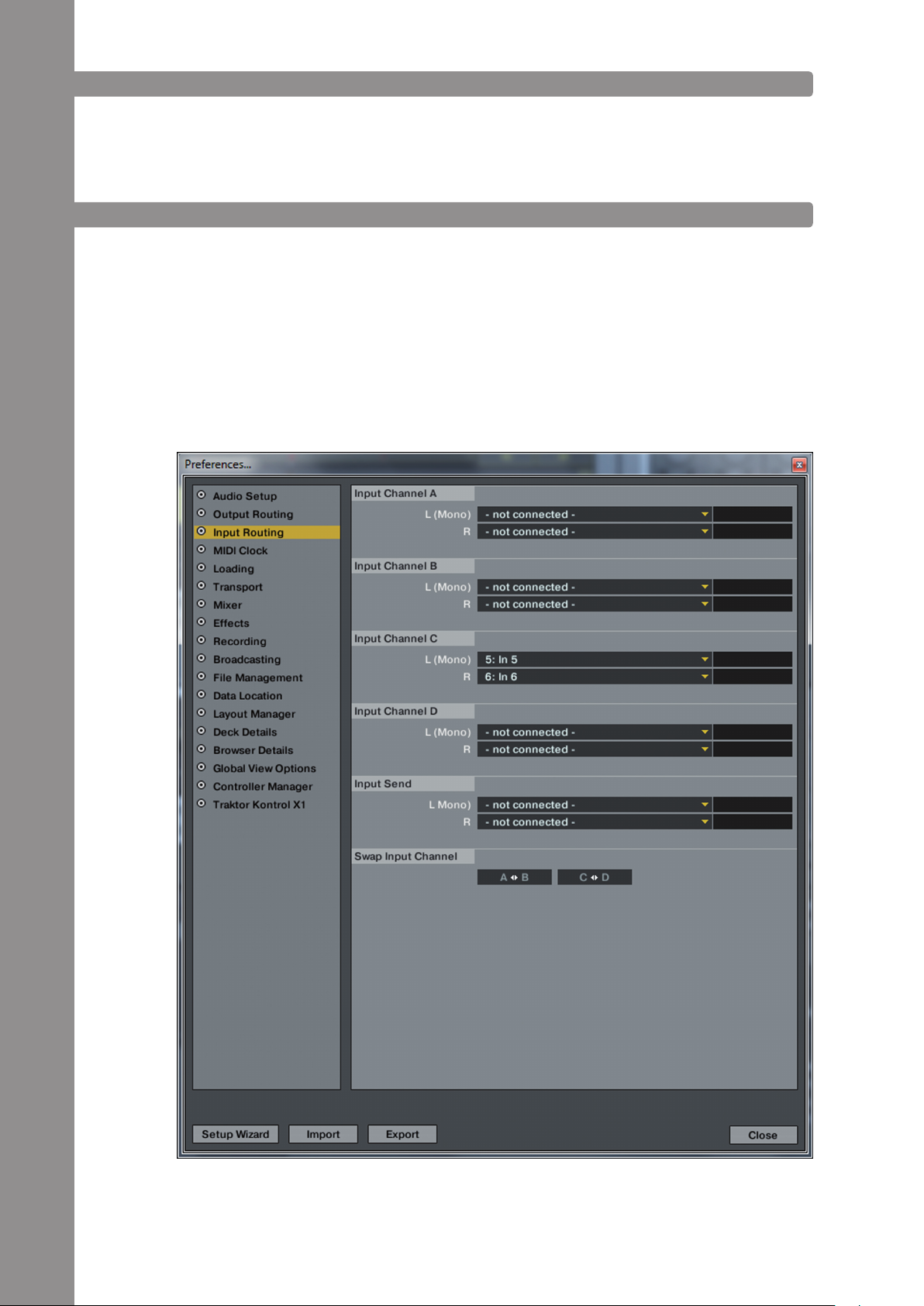
Zunächst müssen in den Einstellungen die richtigen Intputs für das entsprechende Deck gewählt
werden. Im Beispiel wird Deck C als Mikrofon-Kanal verwendet.
DEUTSCH
18
Page 19
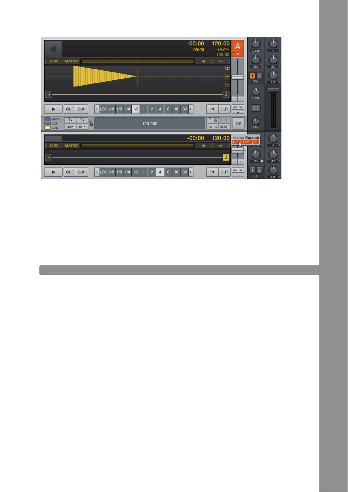
Um das Signal über den Master hörbar zu machen muss das Deck nun noch auf Audio-Thru gestellt werden.
Durch die Verwendung dieser Routig-Option kann das Mikrofon-Signal mit den Traktor-internen Effekten aufgewertet werden.
Thru = Das Mikrofon-Signal wird direkt auf den Master-Ausgang geroutet. Bei dieser Variante wird
kein Kanal in der Software benötigt und eignet sich daher sehr gut für User der Traktor LE Version
oder bei der Verwendung von vier Decks in Traktor Pro.
Off= Das Mikrofon wird stumm geschaltet.
4.2.2. INPUTS
Die beiden Inputs 1 und 2 können mit den Routing-Schaltern -F49- und -F50- wahlweise in die Software (SW) oder auf den Master-Ausgang (MIX) geroutet werden. Die Off-Stellung schaltet die Inputs
aus.
Beispiel-Routing für IN 1:
IN 1 = SW
Das Signal des Input 1 wird nun auf die Input-Channels 1 und 2 geroutet. Traktor Pro muss zu diesem
Zweck noch richtig konguriert werden:
DEUTSCH
19
Page 20
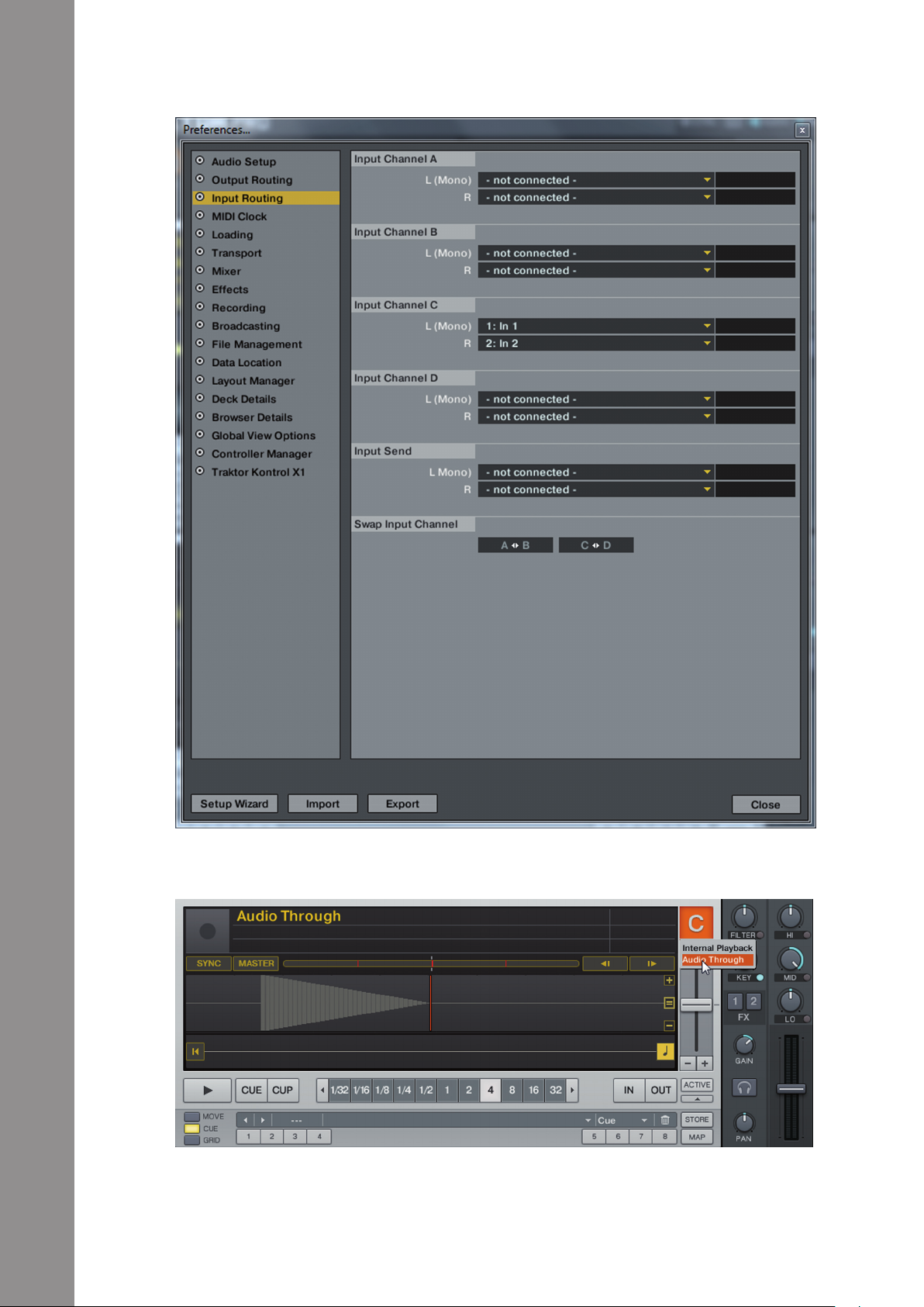
Zunächst müssen in den Einstellungen die richtigen Inputs für das entsprechende Deck gewählt
werden. Im Beispiel wird Deck C als analoger Kanal verwendet.
DEUTSCH
Um das Signal über den Master hörbar zu machen muss das Deck nun noch auf Audio-Thru gestellt werden.
Um das Signal über den Mixer zu steuern muss der Deck-Auswahl-Schalter auf C gestellt sein.
Durch die Verwendung dieser Routig-Option kann das Input-Signal mit den Traktor-internen Effekten
aufgewertet werden.
20
Page 21

IN1 = Mix
Ist das Input-Routing auf MIX geschaltet, so wird das Input-Signal direkt auf den Mixer geroutet.
Wird der Deck-Auswahl-Schalter -30- auf IN1 gesetzt, werden die beiden Decks A und C in Traktor
stumm geschaltet. Lediglich das analoge Signal ist zu hören.
IN1 = Off
IN1 wird stumm geschaltet
4.3. ANALOG-MIXING-FUNKTION
Der Jockey III kann ebenfalls als Zwei-Kanal-Mixer ohne die Einbindung eines Computers genutzt
werden.
Zu diesem Zweck müssen beide Deck-Auswahl-Schalter -T30- auf IN1 bzw. IN2 geschaltet sein. Die
beiden Routing-Schalter -F49- und -F50- müssen auf MIX gestellt sein.
Je nach dem, welche Quellen am Jockey III angeschlossen werden -B66- -B67-, kann man für jedes
Deck zwischen Phono (Plattenspieler) und Line (CD-Player) -B65- umschalten.
Mit den CUE-Tasten -T35- lässt sich das Signal auf jeder Seite vorhören. Mit der CUE-Mix-Überblendung -T40- kann ein Mix schon im Kopfhörer simuliert werden.
4.4. OUTPUTS
Der Jockey 3 verfügt auf der Rückseite über drei Stereo-Ausgangs-Kanäle.
Master 1 -B63- als Cinch-Ausgang sowie Master 2 -B62- als symmetrischer 6,3 mm Klinken-Ausgang
werden über den Master-Lautstärke-Encoder -T37- geregelt.
Der Booth-Ausgang -B64- als Cinch-Ausgang wird über den Booth-Regler -T38- geregelt.
4.5. MASTER-THRU UND CUE-MASTER-THRU
Die Master-Thru Funktion eignet sich vor allem für Setups mit 2 DJs. Das Ausgangssignal des zweiten DJs wird über den 3,5mm Klinkenstecker -B61- durch den Jockey 3 direkt an den Master ausge-
geben. Will man das Signal am Jockey 3 vorhören, so kann die Vorhör-Funktion mit dem CUE-Master-
Thru Schalter -F53- aktiviert werden.
5. GERÄTEEINSTELLUNGEN UND -TESTS
Direkt am Jockey 3 können ganz ohne zu Hilfenahme des Computers einige Einstellungen und Tests
vorgenommen werden. Im Folgenden wird auf einige Punkte genauer eingegangen.
DEUTSCH
5.1. MENU ZUR EINSTELLUNG DER MIDI-CHANNEL-ZUWEISUNG UND DER JOG-WHEEL-AUFLÖSUNG
Um das Einstellungsmenu zu erreichen gehen Sie wie folgt vor:
1. Stellen Sie sicher, dass der Jockey 3 ausgeschaltet ist (siehe Stellung Ein/Aus-Schalter -B56-).
2. Halten Sie die Shift-Taste -T23- gedrückt und schalten Sie den Jockey 3 durch Umlegen des Ein/
Aus-Schalters -B56- ein.
3. Lassen Sie nun die Shift-Taste -T23- los.
Sie haben nun die Möglichkeit die MIDI-Channel-Zuweisung und die Jog Wheel-Auösung zu verändern.
21
Page 22

5.1.1. MIDI-CHANNEL-ZUWEISUNG
ACHTUNG!
Standardmäßig ist der Jockey 3 auf die MIDI-Kanäle 1-4 konguriert. Deck A ist dabei auf dem
1., Deck B auf dem 2., Deck C auf dem 3. und Deck D auf dem 4. Kanal. Die ofziellen Mappings
seitens Reloop sind auf die standardmäßige Konguration ausgelegt. Eine Veränderung ist damit
im Normalfall nicht notwendig.
Sollten Sie dennoch vorhaben, die Decks auf die MIDI-Kanal-Kombinationen 5-8, 9-12 oder 13-16
legen zu wollen, gehen Sie wie folgt vor:
1. Durch Drücken des linken FX Dry/Wet Encoders gelangen Sie in das MIDI-Channel-Zuweisungs-Menu.
2. Mit den CUE-Pads 1 - 4 -T20- können nun die MIDI-Kanäle geändert werden. Das entsprechende
CUE-Pad leuchtet durchgängig auf, während die anderen CUE-Pads aufblinken.
MIDI-Kanal-Kombination CUE-Pad-Taste
1 – 4 1
5 - 8 2
9 - 12 3
13 - 16 4
3. Sind die gewünschten MIDI-Kanäle ausgewählt können Sie diese durch Drücken der Shift-Taste
-T23- dauerhaft speichern.
DEUTSCH
5.1.2. JOG WHEEL-AUFLÖSUNG
Wird Traktor Pro verwendet, ist ein Umstellen der Jog Wheel-Auösung nicht notwendig. Allerdings
unterstützt nicht jede Software die hohe Auösung des im Jockey 3 verbauten Jog Wheels -T22-.
Sollten Sie die Auösung verändern wollen, gehen sie wie folgt vor:
1. Durch Drücken des FX Param. 1 Encoders -T3- gelangen Sie in das Jog Wheel-Auösungs-Menu.
Jog Wheel-Auösung CUE-Pad-Taste
512 1
1024 2
2048 3
4096 4
2
. Mit den CUE-Pads 1 – 4 -T20- kann die Jog Wheel-Auösung umgestellt werden. Das entsprechende
CUE-Pad leuchtet durchgängig auf, während die anderen CUE-Pads aufblinken.
3. Ist die gewünschte Auösung ausgewählt können Sie diese durch Drücken der Shift-Taste -T23-
dauerhaft speichern.
5.2. LED-FUNKTIONSTEST
22
Hiermit können Sie testen, ob alle im Jockey 3 verbauten LEDs einwandfrei funktionieren.
Für den Funktionstest gehen Sie wie folgt vor:
1. Stellen Sie sicher, dass der Jockey 3 ausgeschaltet ist (siehe Stellung Ein/Aus-Schalter -B56-).
2. Halten Sie die linke Sync-Taste -T24- gedrückt und schalten Sie den Jockey 3 durch Umlegen des
Ein/Aus-Schalters -B56- ein.
3. Lassen Sie nun die Sync-Taste -T24- los.
4. Es sollten nun alle LEDs aueuchten.
5. Um den Test abzuschließen, schalten Sie das Gerät über den Ein/Aus-Schalter -B56- einfach aus.
Page 23

5.3. AUTO-SETUP
Hiermit können Sie ein Auto-Setup durchführen. Das Auto-Setup dient zur Problembehebung und
sollte durchgeführt werden, wenn der Jockey 3 nicht richtig reagieren sollte.
1. Stellen Sie sicher, dass der Jockey 3 ausgeschaltet ist (siehe Stellung Ein/Aus-Schalter -B56-).
2. Halten Sie die rechte Play-Taste -T27- gedrückt und schalten Sie den Jockey 3 durch Umlegen des
Ein/Aus-Schalters -B56- ein.
3. Lassen Sie nun die Play-Taste -T27- los.
4. Das Auto-Setup wird nun durchgeführt.
5. Um das Auto-Setup abzuschließen, drücken Sie die rechte Play-Taste -T27- ein weiteres Mal.
5.4. FIRMWARE-VERSIONS-ÜBERPRÜFUNG
Um die aktuelle Firmware-Version des Jockey 3 auszulesen gehen Sie wie folgt vor:
1. Stellen Sie sicher, dass der Jockey 3 ausgeschaltet ist (siehe Stellung Ein/Aus-Schalter -B56-).
2. Halten Sie die rechte Shift-Taste -T23- gedrückt und schalten Sie den Jockey 3 durch Betätigen
des Ein/Aus-Schalters -B56- ein.
3. Die LEDs des linken FX Param.3 Encoders leuchten nun auf. Die Anzahl der aueuchtenden LEDs
entspricht der aktuell installierten Firmware-Version.
4. Zum Beenden der Anzeige lassen Sie die Shift-Taste -T23- los und starten das Gerät neu.
DEUTSCH
5.5. JOG-DRAG
Der Jockey 3 bietet die Funktion den Jog Wheel-Widerstand für jedes Jog Wheel nach eigenen Wünschen anzupassen. Um den Jog-Wheel-Widerstand zu ändern drehen Sie das entsprechende JogDrag -S69- in die gewünschte Position.
5.6. JOG-SENSITIVITY
Mit dem Regler -B58- kann die Jog Wheel Sensitivity eingestellt werden.
5.7. LED-DIMMER
Mit dem Regler -B59- kann die LED-Hintergrundbeleuchtung für alle LEDs eigestellt werden.
6. UPDATES & SUPPORT
6.1. FIRMWARE-UPDATE
6.1 Für den Reloop Jockey 3 besteht die Möglichkeit, dass dessen Firmware aktualisiert werden
kann. Somit können nachträglich Änderungen vorgenommen werden, aber auch neue Features hinzugefügt werden. Eine Anleitung dazu nden Sie online unter unten genannter Adresse.
23
Page 24
Durchführen eines Firmware-Updates
1. Stellen Sie sicher, dass der Jockey 3 ausgeschaltet (siehe Stellung Ein/Aus-Schalter -B56-) und
per USB-Kabel am Rechner angeschlossen ist.
2. Halten Sie die rechte CUP-Taste -T25- und die rechte CUE-Taste -T26- gedrückt und schalten Sie
den Jockey 3 durch Umlegen des Ein/Aus-Schalters -B56- ein.
3. Lassen Sie nun beide Tasten los.
4. Die obersten LEDs des VU-Meter blinken nun auf. Der Jockey 3 bendet sich im Update-Modus.
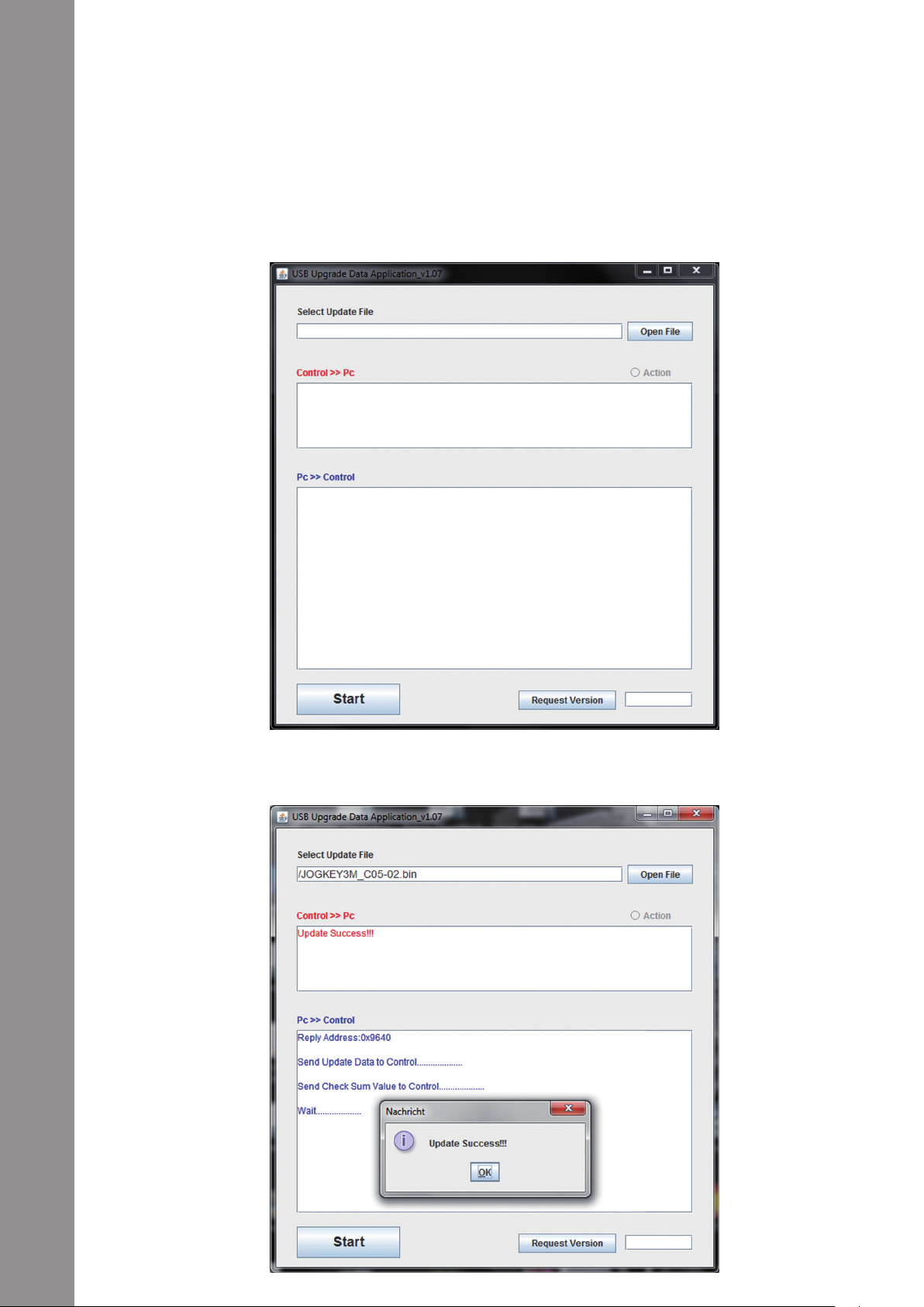
5. Starten Sie nun das Firmware-Update-Tool von der Installations-CD und öffnen die für Ihr Gerät
passende Firmware-Datei.
DEUTSCH
6. Füren Sie nun das Firmware-Update durch indem Sie auf die Schaltäche „Start“ klicken.
7. Die neue Firmware wird nun an das Gerät übertragen.
24
Page 25

8. Nachdem das Update erfolgreich abgeschlossen ist beenden Sie das Firmware-Update-Tool und
starten den Jockey 3 über den Ein/Aus-Schalter -B56- neu.
6.2. TREIBER-UPDATE
Speziell für das integrierte Audio-Interface werden ebenfalls aktualisierte Treiber angeboten, die
heruntergeladen werden können.
6.3. MAPPINGS
Auch werden für Traktor Pro Nachfolgeversionen und andere DJ-Softwares stets aktualisierte Map-
pings bereitgestellt, damit Sie den Reloop Jockey 3 auch in Zukunft verwenden können. Ebenfalls
können speziell auch für abweichende Setups spezielle Mappings geladen werden, die z.T. von der
Nutzergemeinde stammen.
Schauen Sie daher regelmäßig auf folgender Internetseite:
www.reloopdj.com/forum
Neben zahlreichen Downloads steht Ihnen hier auch ein Support zur Verfügung.
DEUTSCH
7. ANHANG
7.1. SYSTEMANFORDERUNGEN TRAKTOR LE
PC:
Windows® XP (aktuellstes Service Pack, 32 Bit) , Windows Vista®/Windows® 7 (aktuellstes Service
Pack, 32/64 Bit)
Intel® Pentium 4® 2.4 GHz oder Intel® Core™ Duo
2 GB RAM
Mac:
Mac OS® X 10.5 oder 10.6 (aktuellstes Update)
Intel® Core™ Duo
2 GB RAM
7.2. MIDI-ZUWEISUNGSTABELLE
MIDI MAP (Hex)
SW name Type MIDI MIDI 2 (Shift) Remarks
TRAX SW/ENC 34/34 73/73
FX SEL.(Adv.) SW/ENC 19/19 58/58
FX SEL.1(Cha.) SW/ENC 1A/1A 59/59
FX SEL.2(Cha.) SW/ENC 1B/1B 5A/5A
FX SEL.3(Cha.) SW/ENC 1C/1C 5B/5B
LENGTH SW/ENC 20/20 5F/5F
MOVE SW/ENC 21/21 60/60
JOG SW/ENC 22/22 61/61
JOG CW SW 23 62 SCRATCH LED =
ON & No Touch
Inner Wheel
25
Page 26

DEUTSCH
SW name Type MIDI MIDI 2 (Shift) Remarks
JOG CCW SW 24 63 SCRATCH LED =
ON & No Touch
Inner Wheel
KEY PITCHBEND/VR PitchBend 2C
GAIN VR 2D 6C
HIGH VR 2E 6D
MID VR 2F 6E
LOW VR 30 6F
CH FADER VR 31 70
FILTER VR/CENTER 32/32 71/71
PAN VR/CENTER 33/33 72/72
CUE/MASTER
FADER
CROSSFADER VR 37 -- CH1 Only
FX ON SW/LED 01/01 40/01
RST SW/LED 02/02 41/02
FX B1 SW/LED 03/03 42/03
FX B2 SW/LED 04/04 43/04
LOOP SW/LED 05/05 44/05
RELOOP SW/LED 06/06 45/06
< BEAT SW/LED 07/07 46/07
BEAT > SW/LED 08/08 47/08
DEL. SW/LED 09/09 48/09
5-8 SW/LED 0A/0A 49/0A
1/5 SW/LED 0B/0B 4A/0B
2/6 SW/LED 0C/0C 4B/0C
3/7 SW/LED 0D/0D 4C/0D
4/8 SW/LED 0E/0E 4D/0E
XF A SW/LED 0F/0F 4E/0F
XF B SW/LED 10/10 4F/10
XF C SW/LED 11/11 50/11
XF D SW/LED 12/12 51/12
TAP SW/LED 13/13 52/13
|< CUE SW/LED 14/14 53/14
CUE > SW/LED 15/15 54/15
KEYLOCK SW/LED 16/16 55/16
LOAD SW/LED 17/17 56/17
PREV SW/LED 18/18 57/18
SHIFT SW 1D -PITCH BEND - SW 1E 5D
PITCH BEND + SW 1F 5E
FX SEL.(Adv.) LED 19 0~7F(0~127) *1
FX SEL.1(Cha.) LED 1A 0~7F(0~127) *1
FX SEL.2(Cha.) LED 1B 0~7F(0~127) *1
FX SEL.3(Cha.) LED 1C 0~7F(0~127) *1
CH Level meter LEVEL 1D 0~A(0~10)
VR 36 -- CH1 Only
26
Page 27

CC-ABSOLUTE (VR)
Control Change messages are sent with status 0xBn, where n is the channel, for the specied CC
controller. Thus the controller MIDI ID is indicated with the channel along with the CC number. The
value from 0x00 to 0x7F, directly related to the location of the controller.
CC-RELATIVE (ENC)
Control Change messages are status 0xBn, where n is the channel, for the specied CC controller.
Thus the controller MIDI ID is indicated with the channel along with the CC number. The value from
0x40 to indicate the change in the controller. This is an offset to 0x40 “one’s complement” notation.
A message with data 0x43 indicates a positive change of 3.
A messages with data 0x31 indicates a negative change of 15.
SWITCH ON/OFF (SW,CENTER,CW,CCW)
These messages are used for switches.
Control Change messages are sent with status 0x9n, SWITCH On and Off value are 0x7F and 0x00,
where n is the channel.
LED ON/OFF (LED)
These messages are used for LED.
Control Change messages are sent with status 0x9n, LED On and Off value are 0x7F and 0x00,
where n is the channel.
PITCHBEND
Pitchbend messages are status 0xEn, where n is the channel, for the specied controller.
Thus the controller ID is indicated only by the channel.
For accurate changes, the 14 bit data in a pitch bend message is reserved for absolute controllers
which require more than 7 bits of data.
LEVEL LED (LEVEL)
These messages are used for LEVEL.
Control Change messages are sent with status 0x9n, LED Off value is 0x00 and On value is related
to LED amount, 0x01 with one LED, 0x02 with two LED…., where n is the channel.
DEUTSCH
27
Page 28

28
DEUTSCH
7.3. TIPPS ZUR FEHLERBEHEBUNG
Sollten Probleme bei der Benutzung von Reloop Jockey 3 auftreten, so ist dies Ihre erste Anlaufstelle,
um diese zu beheben:
Symptome Mögliche Ursachen Korrekturmaßnahmen
Das Gerät bekommt keinen
Strom, wenn man es mit
dem EIN/AUS-Schalter
-B56- einschaltet.
Die LEDs des Controllers
leuchten nur schwach auf
und das Gerät reagiert
nicht.
Es können in der DJ-Software nicht alle Ausgänge
des integrierten AudioInterfaces ausgewählt
werden.
Der Sound des AudioInterfaces ist verzerrt.
Die DJ-Software reagiert
nicht auf die Betätigung
jeglicher Bedienelemente
des Controllers.
Die Decks reagieren nicht
auf die Bedienelemente
des Controllers
Die Inputs werden im
analogen Modus nicht
über den Master-Ausgang
wiedergegeben
Es gibt ein Problem, das
hier nicht aufgeführt ist.
USB-Kabel bzw. Netzstecker nicht richtig verbunden.
Die Spannungsversorgung ist zu gering.
Der ASIO-Treiber ist nicht
richtig installiert.
Der ASIO-Treiber wird
nicht verwendet.
Die Performance-Einstellungen entsprechen
nicht der ComputerLeistung.
Traktor LE ist nicht rich-
tig konguriert.
Traktor Pro ist nicht rich-
tig konguriert.
MIDI Channel ist falsch
gewählt
Die Deck-Auswahl-Schalter stehen auf IN1 / IN2.
Die beiden Input-Schalter
stehen nicht auf MIX.
Diverse Ursachen. Besuchen Sie die Internetseite www.re-
Überprüfen Sie, ob das USB-Kabel
richtig mit einem USB-Port Ihres Computers und mit dem Jockey 3 USB-Port
-B69- verbunden ist. Bitte prüfen Sie
ebenfalls, ob das Steckernetzteil korrekt an dem Netzanschluss -B54- angeschlossen ist.
Schließen Sie Ihren Computer an eine
gesicherte Stromversorgung. Ebenfalls
ist es erforderlich, das mitgelieferte
Steckernetzeil mit dem Netzanschluss
-B54- zu verbinden.
Bitte installieren Sie den ASIO-Treiber
erneut. Lesen Sie dazu bitte den Abschnitt „ASIO Treiber-Installation“ des
Kapitels „Computer-Konguration“.
Bitte stellen Sie sicher, dass der ASIOTreiber installiert ist und auch verwendet wird. Bitte lesen Sie dazu den
Abschnitt „ASIO Treiber-Installation“
des Kapitels „Computer-Konguration“.
Ebenfalls kann es sein, dass im Einstellungsdialog des ASIO-Treibers die
verfügbare Computer-Leistung neu
konguriert werden muss. Öffnen Sie in
Traktor dazu die Einstellungen, wählen die Kategorie „Audio-Setup“ und
klicken auf die „Settings“-Schaltäche
neben dem Soundkarten-Auswahldialog.
Selektieren Sie anschließend im Punkt
„System Performance“4 „Normal“. Bei
anhaltenden Problemen können Sie im
selben Menü auch „Relaxed“ auswählen.
Verwenden Sie die mitgelieferte Traktor
LE-Version, so starten Sie den Setup
Wizard erneut. Lesen Sie dazu bitte den
Abschnitt „Traktor LE-Einrichtung“ des
Kapitels „Computer-Konguration“.
Im Falle von Traktor Pro muss das Mapping erneut geladen werden. Befolgen
Sie dazu die Anweisungen aus dem Ab-
schnitt „Traktor Pro-Konguration“ des
Kapitels „Computer-Konguration“.
MIDI Channel Schalter -B43- am Gerät
überprüfen und in die richtige Stellung
bewegen (Ch. 1 od Ch. 2). Lesen Sie
dazu bitte den Abschnitt „MIDI-Channel-Zuweisung“ des Kapitels „Geräteeinstellungen und -tests“.
Stellen Sie sicher, dass die Deck-Auswahl-Schalter auf die Traktor-Decks
geschaltet sind.
Stellen Sie die beiden Input-Schalter
auf MIX.
loopdj.com/forum, um Support zu Ihren
Reloop-Produkten zu erhalten.
Page 29

7.4. TECHNISCHE DATEN
Folgende Daten des Herstellers werden von der Global Distribution GmbH nicht auf Plausibilität und
Richtigkeit geprüft:
Allgemeine Daten
Stromquelle:. . . . . . . . . . . . . . . . . . . . . . USB 5V 500mA / DC: 6V, 2A;
Maße: . . . . . . . . . . . . . . . . . . . . . . . . . . .420 x 315 x 61,55 mm
Gewicht: . . . . . . . . . . . . . . . . . . . . . . . . .5 kg
USB
2. USB Slave Player Sektion: (Signal Format: MP3, 128kbps, Sony Sound Forge 8.0)
2.1 Output Level: (Sony Sound Audio Dev ice Type: Jockey 3 ME)
Master OUT: . . . . . . . . . . . . . . . . . . . . . .-9 dBV +/-2dB (TCD782 TRK16)
Phones OUT: . . . . . . . . . . . . . . . . . . . . .-10dBV +/-2dB (TCD782 TRK16)
2.2 Frequenzgang: (Sony Sound Audio Device Type: Windows classic Wave Driver)
Master OUT: . . . . . . . . . . . . . . . . . . . . . .17-16 kHz +/-1,5dB (TCD782 TRK1, 4, 16)
2.3 THD+N: (Sony Sound Audio Device Type: Windows classic Wave Driver)
Master OUT: . . . . . . . . . . . . . . . . . . . . . .< 0,01% (TCD782 TRK2, Master VR OUT: 0dB)
Master OUT: . . . . . . . . . . . . . . . . . . . . . .< 0,01% (96K-TDC782 TRK2, Master VR OUT: 0dB)
DEUTSCH
2.4 S/N Ratio: (Sony Sound Audio Device Type: Windows classic Wave Driver)
Master OUT: . . . . . . . . . . . . . . . . . . . . . .> 95dB (TCD782 TRK2, 8; Master VR OUT: 0dB)
2.5 LR Trennung: (Sony Sound Audio Device Type: Windows classic Wave Driver)
Master OUT: . . . . . . . . . . . . . . . . . . . . . .> 85dB ( TCD782 TRT9, 11)
3 Recording und Playback (Line 1Khz, 0dDV, MIC 1KHz -36dB Input, 44.1K Sample Rate 24bit)
3.1 Output+3dBV (1.41V) +/- 1.5dB
THD+N. . . . . . . . . . . . . . . . . . . . . . . . . . .< 0,02% (w/20KHz LPF, A-weighted)
THD+N. . . . . . . . . . . . . . . . . . . . . . . . . . .< 0,02% (w/20KHz LPF, A-weighted 96K Sample Rate 24bit)
3.2 S/N Ratio+3dBV (1.41V) +/- 1.5dB
Line: . . . . . . . . . . . . . . . . . . . . . . . . . . . .> 82dB
Mic: . . . . . . . . . . . . . . . . . . . . . . . . . . . . .> 70dB
Crosstalk: . . . . . . . . . . . . . . . . . . . . . . . .> 75dB zwischen L und R Kanal
29
Page 30

DEUTSCH
30
Page 31

INSTRUCTION MANUAL
CAUTION!
For your own safety, please read this operation manual carefully before initial operation! All persons involved in the installation, setting-up, operation, maintenance and service of this device
must be appropriately qualied and follow this operation manual in detail. This product complies
with the requirements of the applicable European and national regulations. Conformity has been
proven. The respective statements and documents are deposited at the manufacturer.
INDEX
1. Setup . . . . . . . . . . . . . . . . . . . . . . . . . . . . . . . . . . . . . . . 33
1.1. Control Elements . . . . . . . . . . . . . . . . . . . . . . . . . . 33-34
1.2. Connections . . . . . . . . . . . . . . . . . . . . . . . . . . . . . . 35-36
2. Initial Operation. . . . . . . . . . . . . . . . . . . . . . . . . . . . . . . 36
3. Computer Conguration . . . . . . . . . . . . . . . . . . . . . . . . 36
3.1. ASIO Driver Installation . . . . . . . . . . . . . . . . . . . . 36-38
3.2. Traktor LE Setup . . . . . . . . . . . . . . . . . . . . . . . . . . 38
3.2.1. Installation . . . . . . . . . . . . . . . . . . . . . . . . . . . . . . . 38
3.2.2. Conguration . . . . . . . . . . . . . . . . . . . . . . . . . . . . . 38-40
3.3. Traktor PRO Conguration (if applicable). . . . . . 40
3.3.1. Audio-Setup . . . . . . . . . . . . . . . . . . . . . . . . . . . . . . 40
3.3.2.Mapping-Import . . . . . . . . . . . . . . . . . . . . . . . . . . . 41-42
4. Operation . . . . . . . . . . . . . . . . . . . . . . . . . . . . . . . . . . . . 43
4.1. Traktor Function Assignment. . . . . . . . . . . . . . . . 43-46
4.2. Routing Functions . . . . . . . . . . . . . . . . . . . . . . . . . 47
4.2.1. Microphone . . . . . . . . . . . . . . . . . . . . . . . . . . . . . . . 47-48
4.2.2 Inputs. . . . . . . . . . . . . . . . . . . . . . . . . . . . . . . . . . . . 48-50
4.3. Analog Mixing Function. . . . . . . . . . . . . . . . . . . . . 50
4.4. Outputs . . . . . . . . . . . . . . . . . . . . . . . . . . . . . . . . . . 50
4.5. Master-Thru und CUE-Master-Thru . . . . . . . . . . . 50
5. Device Settings & Tests . . . . . . . . . . . . . . . . . . . . . . . . 50
5.1. Menu for MIDI Channel Assigment and . . . . . . . 50
Jog Wheel Resolution Adjustments
5.1.1. MIDI Channel Assignment. . . . . . . . . . . . . . . . . . . 51
5.1.2. Jog Wheel Resolution . . . . . . . . . . . . . . . . . . . . . . 51
5.2. LED Function Test . . . . . . . . . . . . . . . . . . . . . . . . . 51
5.3. Auto Setup . . . . . . . . . . . . . . . . . . . . . . . . . . . . . . . 52
5.4. Firmware Version Check . . . . . . . . . . . . . . . . . . . . 52
5.5. Jog Drag . . . . . . . . . . . . . . . . . . . . . . . . . . . . . . . . . 52
5.6. Jog Sensitivity . . . . . . . . . . . . . . . . . . . . . . . . . . . . 52
5.7. LED Dimmer . . . . . . . . . . . . . . . . . . . . . . . . . . . . . . 52
6. Updates & Support . . . . . . . . . . . . . . . . . . . . . . . . . . . . 52
6.1 Firmware-Update . . . . . . . . . . . . . . . . . . . . . . . . . . 52-54
6.2. Driver Update . . . . . . . . . . . . . . . . . . . . . . . . . . . . . 54
6.3. Mappings. . . . . . . . . . . . . . . . . . . . . . . . . . . . . . . . . 54
7. Appendix . . . . . . . . . . . . . . . . . . . . . . . . . . . . . . . . . . . . . 54
7.1. System Requirements Traktor LE . . . . . . . . . . . . 54
7.2. MIDI Assignment Chart. . . . . . . . . . . . . . . . . . . . . 54-56
7.3. Troubleshooting . . . . . . . . . . . . . . . . . . . . . . . . . . . 57
7.4. Technical Specications . . . . . . . . . . . . . . . . . . . . 58
ENGLISH
Congratulations on purchasing the Reloop Jockey 3 Master Edition. Thank you for placing your trust
in our disc jockey technology. Before operating this equipment we ask you to carefully study and
observe all instructions.
Please remove the Reloop Jockey 3 Master Edition from its packaging. Before initial operation
please make sure that the device has not been visibly damaged during transport. If you detect any
damage to the power cable or the casing, do not operate the device and contact your specialised
dealer.
31
Page 32

SAFETY INSTRUCTIONS
CAUTION!
Please exercise particular caution when handling power voltage. This voltage rating may lead to
a critical electrical shock! Any damage caused by the non-observance of this operation manual
excludes any warranty claims. The manufacturer is not liable for any damage to property or for
personal injury caused by improper handling or non-observance of the safety instructions.
- This device has left the factory in perfect condition. To maintain this condition and to ensure a
risk-free operation the user must observe the safety instructions and warnings contained in this
operation manual.
- For reasons of safety and certication (CE) the unauthorised conversion and/or modication of the
device is prohibited. Please note that in the event of damage caused by the manual modication to
this device any warranty claims are excluded.
- The inside of the device does not contain any parts which require maintenance, with the exception
of wear parts that can be exchanged from the outside. Only qualied staff must carry out maintenance, otherwise warranty does not apply!
- The fuse must exclusively be exchanged against fuses of the same class, with the same trigger
features and nominal current rating.
- Make sure that the power will only be supplied after the device has been fully set up. Always plug
in the mains plug last. Ensure that the mains switch is in the “OFF” position when connecting the
device to power.
- Only use cables that comply with regulations. Make sure that all jacks and bushes are tightened
and correctly hooked up. Refer to your dealer if you have any questions.
-
Ensure that when setting up the product the mains cable is not squashed or damaged by sharp edges.
- Prevent the mains cable from coming into contact with other cables! Exercise great care when
handling mains cables and connections. Never touch these parts with wet hands!
- Connect the power cable exclusively to appropriate shock-proof outlets. The only supply point to
be used is a supply outlet in accordance with specications of the public supply network.
- Disconnect the device from the supply outlet when not in use and before cleaning! Be sure to hold
the mains plug by the body. Never pull the mains cord!
- Position the device on a horizontal and stable low-ame base.
- Avoid any concussions or violent impact when installing or operating the device.
- When selecting the location of installation make sure that the device is not exposed to excessive
heat, humidity, and dust. Be sure that no cables lie around openly. You will endanger your own safety and that of others!
ENGLISH
- Do not rest any containers lled with liquid that could easily spill onto the device or in its immediate vicinity. If, however, uids should access the inside of the device, immediately disconnect
the mains plug. Have the device checked by a qualied service technician before re-use. Damage
caused by uids inside the device is excluded from the warranty.
- Do not operate the device under extremely hot (in excess of 35° C) or extremely cold (below 5° C)
conditions. Keep the device away from direct exposure to the sun and heat sources such as radiators, ovens, etc. (even • during transport in a closed vehicle). Never cover the cooling fan or vents.
Always ensure sufcient ventilation.
- The device must not be operated after being taken from a cold environment into a warm environment. The condensation caused hereby may destroy your device. Do not switch on or operate the
device until it has reached • ambient temperature!
- Controls and switches should never be treated with spray-on cleaning agents and lubricants. This
device should only be cleaned with a damp cloth. Never use solvents or cleaning uids with a petroleum base for cleaning.
- When relocating, the device should be transported in its original packaging.
- When starting operation, the faders and volume controls of your amplier must be set to minimum
level. Bring the loudspeaker switches into the “OFF” position. Wait between 8 to 10 seconds before
increasing the volume to avoid shot noise created by transient effect, which could cause damage
to loudspeakers and the diplexer.
- Devices supplied by voltage should not be left in the hands of children. Please exercise particular
care when in the presence of children.
- At commercial facilities the regulations for the prevention of accidents as stipulated by the organization of professional associations must be observed.
- At schools, training facilities, hobby and self-help workshops the operation of the device must be
monitored with responsibility by trained staff.
- Keep this operation manual in a safe place for later reference in the event of questions or problems.
32
Page 33

APPLICATION IN ACCORDANCE WITH REGULATIONS
- This device is a professional DJ MIDI controller with integrated 6-In / 4-Out soundcard that can
control software. The device should be connected via USB cable to a computer.
- This product is authorised for connection to 240 V, 50 Hz AC via the included mains adapter and
is designed exclusively for indoor application.
- If the device is used for any other purposes than those described in the operation manual, damage
can be caused to the product, leading to exclusion of warranty rights. Moreover, any other application that does not comply with the speci ed purpose harbours risks such as short circuit, re,
electrical shock, etc.
- The serial number determined by the manufacturer must never be removed to uphold the warranty
rights.
MAINTENANCE
- Check the technical safety of the device regularly for damage to the mains cord or the casing, as
well as for wearout of wear parts such as rotary knobs and sliding faders.
- If it is to be assumed that a safe operation is no longer feasible then the device must be disconnected and secured against accidental use. Always disconnect the mains plug from the outlet!
- It must be assumed that a safe operation is no longer feasible if the device bears visible defects,
if the device no longer functions, following longer storage under unfavourable conditions or after
major transport stress.
ENGLISH
1. SETUP
1.1. CONTROL ELEMENTS
T29 T29
T41
T28
T37
T38
T39
T40
T42
T31
T32
T33
T34
T34
T14
T20
T15
T20
T16
T20
T7T4 T5 T6
T17
T20
T1 T1
T12 T12T13 T13
T18 T18T19 T19
T21 T21
T2 T2
T4
T8 T8
T14
T20
T3 T3T3 T3T3 T3
T30 T30
T5 T6
T9 T9
T15
T20
T10 T10T11 T11
T16
T20
T7
T17
T20
T31
T32
T33
T34
T34
T22
T23 T23
T27 T27T24 T24T25 T25T26 T26
T36 T36
T43
T44
T22
33
Page 34

Surface
# Designation Shift Designation
T01 Pitchfader Key
T02 Dry/Wet Control Effect change in Advanced Effect Mode
T03 Effektparameter Effect change in Chained Effect Mode
T04 FX On Button FX Preset 1
T05
T06 Effect Button 1 and FX 2 On respectively FX Preset 3
T07 Effect Button 2 and FX 3 On respectively FX Preset 4
T08 Loop Length
T09 Loop Shift
T10 Filter
T11 Pan(Balance) Control
T12 Pitch Bend Button – FX 1
T13 Pitch Bend Button + FX 2
T14 Auto-loop Function Loop In/Set Cue Button
T15 Reloop Function Loop Out Button
T16 Beatjump Backward Left-Sided GRID Shift
T17 Beatjump Forward Right-Sided GRID Shift
T18 Hot Cue Delete Button
T19 Hot Cue Bank Select
T20 Hot Cue Buttons Sample Player 1 – 8
T21 Jog Wheel Mode Buttons
T22 Jog Wheel
T23 Shift Button
T24 Sync Button Deck Master Select
T25 Cup Button Beat Tab
T26 Cue Button FX Mode
ENGLISH
T27 Play/Pause Button Keylock
T28 TRAX Encoder Folder Navigation
T29 Load Button Preferences Folder Navigation
T30 Deck Select Switch
T31 Gain Control
T32 EQ Control High
T33 EQ Control Mid
T34 EQ Control Low
T35 Monitor Cue Button
T36 Linefader
T37 Master Volume
T38 Booth Volume
T39 Headphones Volume
T40 Cue Mix Fading
T41 Power LED
T42 MIDI Signal LED
T43 VU-Meter
T44 Crossfader
Effect Reset and FX 1 On respectively
FX Preset 2
Preview-Player Load&Play and Stopp respectively
34
Page 35

1.2. CONNECTIONS
F45
B54
B57B56B55
F46 F47
Rear Side
# Designation
B54 Mains Cord Strain Relief
B55 Mains Adapter Connection (DC 6V/1,5A)
B56 ON/OFF Switch
B57 USB Port
B58 Jog Wheel Sensitivity
B59 LED Dimmer
B60 Shift Lock Switch
B61 3.5 mm Jack Master-Thru Input
B62 6.3 mm Jack Master 2 Audio Output (balanced)
B63 RCA Master 1 Audio Output
B64 RCA Booth Audio Output
B65 Line/Phono Switch
B66 RCA Input 2
B67 RCA Input 1
B68 Grounding Screw
B65
B62B61B60B59B58
B63
B64
F48 F49 F50
B65
B66
F51
B67
B65
F52
F53
ENGLISH
Front Side
# Designation
F45 6.3 mm Jack Microphone Connection
F46 Microphone Volume
F47 Microphone Routing Switch
F48 Crossfader Curve
F49 Input 1 Routing Switch
F50 Input 2 Routing
F51 6.3 mm Jack Headphones Connection
F52 3.5 mm Jack Headphones Connection
F53 Master Thru Routing Switch
35
Page 36

Lateral View
# Designation
S69 Jog Wheel Drag
S70 Kensington Lock
2. INITIAL OPERATION
- First make sure to turn off the device via the ON/OFF Button -B56- on the rear panel.
- Connect the included mains adapter to the device‘s DC jack -B55- and a shock-proof outlet.
- Then connect the included USB cable to the corresponding connection -B57- on the device‘s rear
panel and a free USB port of your computer.
3. COMPUTER CONFIGURATION
Before you can use your new device a few basic computer adjustments have to be carried out.
ATTENTION!
Please make sure that your Reloop Jockey 3 is still turned off. You will be asked during the installation to turn the device on.
The included USB cable can already be connected.
Please pay special attention to the following explanations.
3.1 ASIO DRIVER INSTALLATION
Insert the included installation CD in your computer‘s drive. Select the driver that best suits your
system in the „Drivers“ folder and start the installation via a double click.
TIP!
ENGLISH
Reloop regularly provides updated drivers online. For more information please read the chapter
„Updates & Support“.
NOTE!
Please make sure to start the driver installation with admin rights. Otherwise the installation will
fail with an error message.
When using Windows Vista or Windows 7 please carry out the appropriate installation setup via a
click of the right mouse button. Then select „Run as admin“.
1. First of all you will enter the language select window. Please select your preferred language.
36
Page 37

2. Now click on the „Install the driver“ button.
3. You will then be asked to connect and turn on your Reloop Jockey 3. If your Reloop Jockey 3 is not connected via USB yet, please connect the included USB cable to the USB port -B57- and a free USB port
of your computer. Also connect the included mains adapter to the corresponding connector -B55-.
Now turn on the device via the ON/Off Button -B56-.
4. The installation will be continued. As soon as the installation has been carried out successfully
you can close the setup via the „Finish“ button. A reboot is not necessary.
ENGLISH
37
Page 38

3.2 TRAKTOR LE SETUP
Along with Reloop Jockey 3 you receive the gratuitous and non-restrictive DJ software „Traktor LE“.
NOTE!
Upgrade to Traktor Pro (4 deck support):
Via the included Traktor LE version you can purchase the extensive Traktor Pro version at a bargain price. Current price conditions can be found under www.nativeinstruments.de
ENGLISH
3.2.1 INSTALLATION
Besides the ASIO drivers, you can also nd a directory named „Traktor“ on the included installation
CD. Open this directory and select the setup le that best suits your system. Follow the instructions
from the installation window.
NOTE!
Details regarding the system requirements can be found in the appendix under the item „System
Requirememts Traktor LE“.
3.2.2 CONFIGURATION
When using Traktor LE for the rst time the „Setup Wizard“ should start. If this is not the case please click on „Help“ and select the menu item „Start Setup Wizard“. In the setup wizard select the
following items:
1.
Answer the rst question „Are you using a USB/FireWire Controller?“ with „Yes“. Then click on „Next“.
2. In the eld „Choose your manufacturer“ select the item „Reloop“. The following menu item
„Choose your model“ has to be answered with „Jockey 3 Master LE“. Again conrm this selection
with „Next“.
3. The following questions regarding connected hardware by manufacturer „Native Instruments“
has to be answered with „No“.
Your Reloop Jockey 3 should now be congured accordingly for Traktor LE.
38
Page 39

NOTE!
By default the audio setup should be adjusted to internal mixing mode.
If this is not the case, please pay close attention to the following items.
Otherwise you can skip this chapter and continue with the chapter „Operation“.
Audio Setup:
Internal Mixing Mode
1. In Traktor open the setup dialogue by clicking the small cog wheel in the upper right corner.
2. Open the catagory „Audio Setup“ and in the led „Audio Device“ select the item „Reloop Jockey 3“.
ENGLISH
39
Page 40

3. Open the category „Output Routing“ and in the eld „Mixing Mode“ select the button „Internal“.
For channel assignment please see the following example.
ENGLISH
3.3 TRAKTOR PRO CONFIGURATION (IF APPLICABLE)
If you already possess Traktor Pro or you have upgraded Traktor LE at a lower-cost price, it is possible to fully utilize all Jockey 3 functions.
Pay close attention to the following points in order for Traktor to be able to work in combination with
Jockey 3.
3.3.1 AUDIO SETUP
The audio setup does not differ from the Traktor LE audio setup. Please proceed as described under
item 3.2.2.
40
Page 41

3.3.2 MAPPING IMPORT
In order for Traktor to be able to assign the MIDI commands sent by the Jockey 3 to the correct
functions, a special mapping is necessary.
A suitable mapping can be found on the installation CD in the folder „Mappings/Traktor Pro“.
NOTE!
You can nd updated and extended mappings online. Go to http://www.reloopdj.com/forum and
open the category „Mapping les“ in the eld „Downloads for all Reloop products“.
Please proceed as follows in order to import the mapping:
1. In Traktor open the adjustment dialogue by clicking the small cog wheel in the upper right corner.
2. Open the category „Controller Manager“.
3. In order to avoid problems it is recommended to delete all existing entries apart from the keyboard mappings from the controller manager: To do so select one entry after the other in the eld
„Device“ and press „EDIT...“ followed by „Delete“.
ENGLISH
41
Page 42

4. Now select the button „Add...“ followed by „Import“.
ENGLISH
In the select screen open the mapping le that is found on the CD or that was downloaded from the
Reloop support site.
Troubleshooting
Should a problem arise and the Jockey 3‘s LEDs are not lit correctly, in most cases this is probably caused
by installed MIDI software (e.g. MidiYoke, Maple Virtual MIDI Cable, OSCulator, Bome Midi Translator etc.).
In order to solve the problem proceed as follows:
1. In Traktor open the adjustment dialogue by clicking the small cog wheel in the upper right corner.
2. Open the category „Controller Manager“.
3. For the following device entries the following port assignments have to be congured:
Device In-Port Out-Port
Jockey 3 V* (Deck A) Reloop Jockey 3 Reloop Jockey 3
Jockey 3 V* (Deck B) Reloop Jockey 3 Reloop Jockey 3
Jockey 3 V* (Deck C) Reloop Jockey 3 Reloop Jockey 3
Jockey 3 V* (Deck D) Reloop Jockey 3 Reloop Jockey 3
Jockey 3 V* (Mixer) Reloop Jockey 3 Reloop Jockey 3
Jockey 3 V* (FX Presets) Reloop Jockey 3 Reloop Jockey 3
42
Page 43

4. OPERATION
After connecting and conguring Reloop Jockey 3 correctly for the DJ software, Traktor can now be
used. If Traktor Pro is used, it is possible to fully utilize the Jockey 3 user interface. There are some differences for Traktor LE regarding effect control, the number of usable decks and the hot cue assignment.
4.1 TRAKTOR FUNCTION ASSIGNMENT
NOTE!
In the following the whole Traktor function assignment will be described. Some features are
only available in Traktor Pro and therefore they have been marked grey in the following chart.
Element Funktion Funktion bei aktivem Shift -T3-
T1 Pitchfader
Herewith it is possible to adjust the current
deck's (see -T30-) pitch.
T2 Dry/Wet Dial
With this encoder it is spossible to adjust the
effect‘s intensity.
T3 Effect Parameter <Advanced E.>
In Advanced Effect Mode the parameters can
be adjusted herewith.
Dry/Wet Fine Adjustment <Chained E.>
If Chained Effect Mode is used, the single effects can be operated.
NOTE!
In Traktor LE only the 1st parameter in Chained
Effect Mode works.
T4 FX On Button <Advanced E.>
Activates the Advanced FX Section correspon-
ding to the deck (Deck A 4 FX1, Deck B 4 FX2,
Deck C 4 FX3, Deck D 4 FX4)
T5 Effect Reset Function <Advanced E.>
In Advanced Effect Mode it is possible to reset
the effect herewith.
FX 1 On <Chained E.>
Activates and deactivates the 1st effect in
Chained Effect Mode respectively.
T6 Effect Button 1 <Advanced E.>
Activates and deactivates the Effect Button 1
in Advanced Effect Mode.
FX 2 On <Chained E.>
Activates and deactivates the 2nd effect in
Chained Effect Mode respectively.
T7 Effect Button 2 <Advanced E.>
Activates and deactivates the Effect Button 2
in Advanced Effect Mode.
FX 3 On <Chained E.>
Activates and deactivates the 3rd effect in
Chained Effect Mode.
T8 Loop Length
Turning the encoder varies a set loop‘s length.
Pressing the encoder activates and deactivates the Loop Active Function respectively.
T9 Loop Shift
Turning the encoder shifts a set loop‘s positi-
on.
Pressing and simultaneously turning the encoder determines the movement‘s step size.
Keyfader
Herewith it is possible to adjust
the current deck‘s key.
Effekt Change <Advanced E.>
If the Advanced Effect section is
selected, it is possible to change
the effect by turning the encoder.
Effect Change <Chained E.>
In Chained Effect Mode it is
herewith possible to change the
respective effect.
NOTE!
In Traktor LE only the 1st effect
from the effect section works.
FX-Preset-1-Taste
consists of:
Beatmasher 2
Digital LoFi
Reverse Grain
FX Preset 1 Button
consists of:
Beatmasher 2
Digital LoFi
Reverse Gain
FX Preset 3 Button
consists of:
Beatmasher 2
Reverb
Reverse Gain
FX-Preset-4-Taste
consists of:
Delay
Filter
Reverb
ENGLISH
43
Page 44

Element Funktion Funktion bei aktivem Shift -T3-
T10 Filter
Adjusts the lter effect for the active deck. In
zero position the lter is automatically turned
off.
T11 Pan Dial
Herewith it is possible to adjust the volume
assignment for the left and right channel.
Zero position corresponds to an equal level on
both channels.
T12 Pitchbend Button
Slows down the deck‘s pitch.
T13 Pitchbend Button
Increases the deck‘s pitch.
T14 Autoloop Function
Sets an automatic loop with the set loop length
(-T9-) without the need to manually set the
loop ending point.
T15 Reloop Function
Jumps to the last set loop, reactivating it.
T16 Beat Jump Backward
Executes a beat jump opposed to playback
direction.
T17 Beat Jump Forward
Executes a beat jump in playback direction.
T18 Hot Cue Delete Button
While this button is being pressed and held it is
possible to delete stored cue points by pres-
ENGLISH
T19 Hot Cue Bank Select
T20 Hot Cue Buttons
sing the corresponding Hot Cue Pads -T20-.
The LED corresponding to the respective Pad
will go out.
Selects the desired Hot Cue Bank. If the LED
is not lit, cue bank 1-4 is selected. Pressing the
button „5-8“ allows the operation of Hot Cues
5-8 via the Hot Cue Buttons -T20-.
Herewith it is possible to operate the 8 Hot
Cues of a track in Traktor. Depending on the
active bank (see -T19-), Hot Cues 1-4 or 5-8 can
be selected.
If a Hot Cue is unassigned (no LED feedback),
it is possible to assign it to the current track‘s
position by pressing one of the Pads -T20-.
FX Routing Button 1
Herewith it is possible to assign
FX Unit 1 to the current deck.
FX Routing Button 2
Herewith it is possible to assign
FX Unit 2 to the current deck.
Loop In/Set Cue Button
Manually sets a loop‘s starting
point. Simultaneously a cue point
will be dened.
Loop Out Button
Manually sets a loop‘s ending
point. Now the deck is in loop
mode; the set passage will now be
continuously repeated. Repressing
the button will end loop mode.
Left-Sided GRID Shift
Shifts the grid that Traktor puts
over the bass line a step to the
left.
Left-Sided GRID Shift
Shifts the grid that Traktor puts
over the bass line a step to the
left.
44
Page 45

Element Funktion Funktion bei aktivem Shift -T3-
T21
T22 Jog Wheel
T23 Shift Button
T24 Sync Button
T25 Cup Button
T26 Cue Button
T27 Play/Pause Button
T28 Tracklist Navigation
T29 Load Buttons
T30 Deck Select Switch
Jog Wheel Mode Buttons
There are 4 modes at your disposal which determine the jog wheel‘s function.
- SCRATCH
If this mode is active, it is possible to scratch
the current track as long as the jog wheel‘s
-T22- surface is being touched. If only the side
is being touched, the current track‘s pitch can
be increased (clockwise) or decreased (counterclockwise).
- PITCH BEND
Herewith it is possible to increase (clockwise) or
decrease (counterclockwise) the track‘s pitch.
As opposed to SCRATCH mode the jog wheel‘s
-T28- rotational speed inuences a track‘s
manipulation.
- SEARCH
Allows quick scrolling through a loaded track.
- TRAX
By activating this mode Traktor automatically
switches to browse view. Now it is possible to
navigate comfortably through the track list via
the Jog wheel -T22-.
A complete navigation in folder as well as track
list in Traktor can be executed via the TRAXEn-
coder -T28-.
Herewith it is possible to execute various
functions. Please refer to the jog wheel mode
buttons -T21-.
By pressing this button all the device‘s control
elements receive a different function assignment. The current assignment can be viewed
on the right side of this chart.
The current track‘s pitch will be synchronized
to the master deck.
As long as this button is being pressed and
held, the deck jumps to the last set cue point
and stops. Releasing the button will start
playback.
Herewith the cue point will be called up and
played as long as the button is being pressed.
Starts and pauses the track‘s playback respectivley.
- By turning the encoder it is possible to scroll
through the track list.
- By pressing the encoder browse view will be
maximized.
By pressing this button the selected track will
be assigned to the respective deck.
Via this switch it is possible to select the controlable decks. If the switch is in the Input position, the mixer can be used as analog mixer.
Crossfader Select Buttons
Via these buttons it is possible to
determine which deck is routed to
which crossfader side.
Master Deck Assignment
The current deck becomes the
master deck.
Tap Button
Determines the track‘s pitch, depending on how quickly the button
will be repeatedly pressed. Ideally
it should be pressed to every beat
should the grid not be tting.
FX Mode Button
Herewith it is possible to switch
between Advanced Effect Mode
and Chained Effect Mode.
Keylock
(De-)activates Keylock.
Folder Navigation
- By turning the encoder it is possible to navigate the folder list.
- Pressing the encoder opens and
closes the selected folder.
Favorites Navigation
Via these buttons it is possible to
scroll through the favorites.
ENGLISH
45
Page 46

Element Funktion Funktion bei aktivem Shift -T3-
T31 Gain Dial
With this dial it is possible to adjust the deck‘s
volume.
T32 EQ Dial High
Via this dial the high frequencies can be adjusted.
T33 EQ Dial Mid
Via this dial the middle frequencies can be
adjusted.
T34 EQ Dial Low
Via this dial the low frequencies can be adjusted.
T35 Cue Monitor
Via this button it is possible to monitor the
selected deck.
T36 Linefader
Via the linefader the channel‘s volume can be
adjusted.
T37 Master Volume
Via this dial the master volume can be adjusted.
This dial is analog and does not send a MIDI
signal.
T38 Booth Volume
Via this dial the booth output volume can be
adjusted.
This dial is analog and does not send a MIDI
signal.
T39 Headphones Volume
Via this dial the headphones‘ volume can be
adjusted.
This dial is analog and does not send a MIDI
signal.
T40 Cue Mix Fading
ENGLISH
T41 Power LED
T42 MIDI Status LED
T43 VU Meter
T44 Crossfader
F48 Crossfader Curve
Via the Cue Mix dial a pre-mix can be simulated via the headphones. In right position the
master signal is audible, in left position the cue
signal is audible.
The Power LED shows that the Jockey 3 disposes of a sufcient power supply.
The MIDI Status LED shows that MIDI com-
mands are being sent by the controller.
The VU Meter shows the selected decks‘ input
level.
Via this fader it is possible to fade between the
decks. Please also see -T21-.
Herewith it is possible to adjust the
crossfader‘s curve. Long > Cut.
Preview Player Buttons
Via these buttons the selected
track will be assigned to the
Preview Player and the track will
start and stop respectively.
46
Page 47

4.2 ROUTING FUNCTIONS
The Jockey 3 disposes of various routing options in order to include already existing equipment.
4.2.1 MICROPHONE
On the device‘s front panel a microphone can be included via a 6.3 mm jack -F45-. Besides a volume
dial -46- there is also a Routing Switch -47- that operates the following routing options:
SW = The microphone‘s signal is routed to the software. For this function a free deck for the mic
signal is necessary. In Traktor Pro it is additionally necessary to congure the input, as described
below:
First it is necessary to select the correct inputs for the respective deck. In this example deck C is
used as microphone channel.
ENGLISH
47
Page 48

In order to make the signal become audible via master, the deck has to be switched to Audio Thru.
By using this routing option the mic signal can be enhanced with Traktor‘s internal effects.
Thru = The mic‘s signal is directly routed to the master output. With this variant a signal in the software is not necessary, thus becoming especially adequate for Traktor LE users or when using four
decks in Traktor Pro.
Off = The mic becomes mute.
4.2.2 INPUTS
Inputs 1 and 2 can be routed to the software (SW) or Master Output (Mix) via the Routing Switches
ENGLISH
-F49- and -F50-. The Off position will turn off the inputs.
Example routing for IN1:
IN1 = SW
The signal of Input 1 will now be routed to the Input Channels 1 and 2. For this purpose Traktor Pro
has to be congured correctly.:
48
Page 49

First the correct inputs for the corresponding deck have to be selected. In this example deck C is
used as analog channel.
In order to make the signal become audible via Master, the deck has to be switched to Audio Thru.
ENGLISH
In order to operate the signal via the mixer the Deck Select Switch has to be put to C.
By using this routing option the input signal can be enhanced with the internal Traktor effects.
49
Page 50

IN1 = Mix
If the Input Routing is switched to MIX, the input signal will be routed directly to the mixer. If the
Deck Select Switch -30- is switched to IN1 both decks A and C in Traktor are mute. Only the analog
signal is audible.
IN1 = Off
IN1 is switched to mute.
4.3 ANALOG MIXING FUNCTION
The Jockey 3 can also be used as 2 channel mixing console without the necessity to involve a computer.
To do so both Deck Select Switches -T30- have to be switched to IN1 and IN2 respectively. Both Routing Switches -F49- and -F50- have to be switched to MIX.
Depending on which sources are connected to the Jockey 3 -B66-, -B67-, it is possible to switch each
deck to phono (turntables) or line (CD-players) -B65-.
Via the Cue Buttons -T35- it is possible to monitor the signal on each side. Via the Cue Mix Fader
-T40- it is possible to simulate a mix through your headphones.
4.4 OUTPUTS
The jockey 3 disposes of three stereo output channels on the device‘s rear side.
Master 1 -B63- as RCA output as well as Master 2 -B62- as symmetrical 6.3 mm jack output are
adjusted via the Master Volume Encoder -T37-.
The Booth Output -B64- as RCA output is adjusted via the Booth Dial -T38-.
4.5 MASTER THRU AND CUE MASTER THRU
The Master Thru function is especially convenient for setups with 2 DJs. The second DJ‘s output signal
is emitted via the 3.5 mm jack -B61- through the Jockey 3 to master. If you wish to monitor the signal
at the Jockey 3, the monitoring function can be activated with the Cue Master Thru Switch -F53-.
ENGLISH
5. DEVICE SETTINGS & TESTS
A few adjustments and tests can be carried out with the Jockey 3 directly, without the need for a
computer. In the following a few items are explained in detail.
5.1 MENU FOR MIDI CHANNEL ASSIGNMENT
AND JOG WHEEL RESOLUTION ADJUSTMENTS
In order to access the setup menu proceed as follows:
1. Make sure that the Jockey 3 is turned off (see position On/Off Button -B56-).
2. Press and hold the Shift Button -T23- and turn on the Jockey 3 via the On/Off Button -B56-.
3. Now release the Shift Button -T23-.
Now you have the possibility to adjust the MIDI channel assignment and the jog wheel resolution.
50
Page 51

5.1.1 MIDI CHANNEL ASSIGNMENT
NOTE!
By default the Jockey 3 is congured for MIDI channels 1-4. Deck A is assigned to channel 1, Deck B is
assigned to channel 2, Deck C is assigned to channel 3 and Deck D is assigned to channel 4. Reloop‘s
ofcial mappings are laid out for the standard conguration. An adjustment is usually not necessary.
However, if you wish to switch the decks to the MIDI channel combinations 5-8, 9-12 or 13-16, please
proceed as follows:
1. By pressing the left FX Dry/Wet Encoder you will access the MIDI channel assignment menu.
2. Via the CUE Pads 1-4 -T20- it is now possible to adjust the MIDI channels. The corresponding Cue
Pad is illuminated while the other Cue Pads are blinking.
MIDI Channel Combination CUE Pad Button
1 – 4 1
5 - 8 2
9 - 12 3
13 - 16 4
3. When the desired MIDI channels have been selected, it is possible to store these permanently by
pressing the Shift Button -T23-.
ENGLISH
5.1.2 JOG WHEEL RESOLUTION
If Traktor Pro is being used, an adjustment of the jog wheel resolution is not necessary. However, not
every software supports the high resolution of the Jockey 3‘s jog wheel -T22-. If you wish to adjust
the resolution please proceed as follows:
1. By pressing the FX Parameter 1 Encoder -T3- you will access the jog wheel resolution menu.
Jog-Wheel-Resolution CUE-Pad-Button
512 1
1024 2
2048 3
4096 4
2. Via the CUE Pads 1-4 -T20- the jog wheel resolution can be adjusted. The corresponding CUE Pad
is illuminated while the remaining CUE Pads ash.
3. When the desired resolution has been selected, it is posible to store it permanently by pressing
the Shift Button -T23-.
5.2 LED FUNCTION TEST
Herewith you can check whether all LEDs that have been integrated in the Jockey 3 are working correctly.
For the function test proceed as follows:
1. Make sure that the Jockey 3 is turned off (see position On/Off Button -B56-).
2. Press and hold the left Sync Button -T24- and turn on the Jockey 3 via the On/Off Button -B56-.
3. Now release the Sync Button -T24-.
4. Now all LEDs should be lit.
5. In order to complete the test simply turn off the device via the On/Off Button -B56-.
51
Page 52

5.3 AUTO SETUP
Herewith it is possible to carry out an auto setup. The auto setup is used to solve problems and
should be carried out in case the Jockey 3 does not work correctly.
1. Make sure that the Jockey 3 is turned off (see position On/Off Button -B56-).
2. Press and hold the right Play Button -T27- and turn on the Jockey 3 via the On/Off Button -B56-.
3. Now release the Play Button -T27-.
4. The auto setup will now be carried out.
5. In order to complete the auto setup press the right Play Button once again -T27-.
5.4 FIRMWARE VERSION CHECK
In order to verify your current Jockey 3 rmware version proceed as follows:
1. Make sure that the Jockey 3 is turned off (see position On/Off Button -B56-).
2. Press and hold the right Shift Button -T23- and turn on the Jockey 3 via the On/Off Button -B56-.
3. The LEDs of the left FX Parameter 3 Encoder will now be illuminated. The number of illuminated
LEDs corresponds to the currently installed rmware version.
4. In order to stop this display release the Shift Button -T23- and reboot the device.
5.5 JOG DRAG
The Jockey 3 offers the possibility to adjust the jog wheel‘s drag for each jog wheel, according to
one‘s desires. In order to adjust the jog wheel‘s drag turn the respective Jog Drag -S69- to the desi-
red position.
5.6 JOG SENSITIVITY
Via the dial -B58- the jog wheel sensitivity can be adjusted.
ENGLISH
5.7 LED DIMMER
Via the dial -B59- the LED background illumination for all LEDs can be adjusted.
6. UPDATES & SUPPORT
6.1 FIRMWARE UPDATE
For the Reloop Jockey 3 it is possible to update its rmware. Consequently it is possible to carry
out adjustments as well as add new features. An instruction regarding this issue can be found online
under the below mentioned address.
52
Page 53

How to carry out a rmware update
1. Make sure that the Jockey 3 is turned off (see position On/Off Button -B56-) and connected via
USB to your computer.
2. Press and hold the right CUP Button -T25- and the right CUE Button -T26- and simultaneously
turn on the Jockey 3 via the On/Off Button -B56-.
3. Now release both buttons.
4. Now the upper LEDs of the UV meter blink. The Jockey 3 is now in update mode.
5. Start the rmware update tool from the installation CD and open the rmware le that corresponds to your computer.
6. Carry out the rmware update by clicking the „Start“ button.
7. The new rmware will be uploaded to the device.
ENGLISH
53
Page 54

8. After the successful update exit the rmware update tool and reboot your Jockey 3 via the On/
Off Button -B56-.
6.2 DRIVER UPDATE
Updated drivers for the integrated audio interface that can be downloaded are also offered.
6.3 MAPPINGS
Follow-up versions for Traktor Pro and other DJ softwares
Updated mappings for follow-up versions of Traktor Pro and other DJ softwares are also always provided, so that the Jockey 3 can also be utilized in the future. For differing setups it is also possible
to download special mappings that, in part, derive from the user community. Therefore regularly
check the following website:
www.reloopdj.com/forum
Besides numerous downloads you can also nd a support here.
7. APPENDIX
7.1 SYSTEM REQUIREMENTS TRAKTOR LE
PC:
- Windows XP (latest Service Pack, 32 bit), Windows Vista/Windows 7 (latest Service Pack, 32/64 bit)
- Intel Pentium 4 2.4 GHz or Intel Core Duo
- 2 GB RAM
ENGLISH
Mac:
- Mac OS X 10.5 or 10.6 (latest update)
- Intel Core Duo
- 2 GB RAM
7.2 MIDI ASSIGNMENT CHART
MIDI MAP (Hex)
SW name Type MIDI MIDI 2 (Shift) Remarks
TRAX SW/ENC 34/34 73/73
FX SEL.(Adv.) SW/ENC 19/19 58/58
FX SEL.1(Cha.) SW/ENC 1A/1A 59/59
FX SEL.2(Cha.) SW/ENC 1B/1B 5A/5A
FX SEL.3(Cha.) SW/ENC 1C/1C 5B/5B
LENGTH SW/ENC 20/20 5F/5F
MOVE SW/ENC 21/21 60/60
JOG SW/ENC 22/22 61/61
JOG CW SW 23 62 SCRATCH LED =
ON & No Touch
Inner Wheel
54
Page 55

SW name Type MIDI MIDI 2 (Shift) Remarks
JOG CCW SW 24 63 SCRATCH LED =
ON & No Touch
Inner Wheel
KEY PITCHBEND/VR PitchBend 2C
GAIN VR 2D 6C
HIGH VR 2E 6D
MID VR 2F 6E
LOW VR 30 6F
CH FADER VR 31 70
FILTER VR/CENTER 32/32 71/71
PAN VR/CENTER 33/33 72/72
CUE/MASTER
FADER
CROSSFADER VR 37 -- CH1 Only
FX ON SW/LED 01/01 40/01
RST SW/LED 02/02 41/02
FX B1 SW/LED 03/03 42/03
FX B2 SW/LED 04/04 43/04
LOOP SW/LED 05/05 44/05
RELOOP SW/LED 06/06 45/06
< BEAT SW/LED 07/07 46/07
BEAT > SW/LED 08/08 47/08
DEL. SW/LED 09/09 48/09
5-8 SW/LED 0A/0A 49/0A
1/5 SW/LED 0B/0B 4A/0B
2/6 SW/LED 0C/0C 4B/0C
3/7 SW/LED 0D/0D 4C/0D
4/8 SW/LED 0E/0E 4D/0E
XF A SW/LED 0F/0F 4E/0F
XF B SW/LED 10/10 4F/10
XF C SW/LED 11/11 50/11
XF D SW/LED 12/12 51/12
TAP SW/LED 13/13 52/13
|< CUE SW/LED 14/14 53/14
CUE > SW/LED 15/15 54/15
KEYLOCK SW/LED 16/16 55/16
LOAD SW/LED 17/17 56/17
PREV SW/LED 18/18 57/18
SHIFT SW 1D --
PITCH BEND - SW 1E 5D
PITCH BEND + SW 1F 5E
FX SEL.(Adv.) LED 19 0~7F(0~127) *1
FX SEL.1(Cha.) LED 1A 0~7F(0~127) *1
FX SEL.2(Cha.) LED 1B 0~7F(0~127) *1
FX SEL.3(Cha.) LED 1C 0~7F(0~127) *1
CH Level meter LEVEL 1D 0~A(0~10)
VR 36 -- CH1 Only
ENGLISH
55
Page 56

CC-ABSOLUTE (VR)
Control Change messages are sent with status 0xBn, where n is the channel, for the specied CC
controller. Thus the controller MIDI ID is indicated with the channel along with the CC number. The
value from 0x00 to 0x7F, directly related to the location of the controller.
CC-RELATIVE (ENC)
Control Change messages are status 0xBn, where n is the channel, for the specied CC controller.
Thus the controller MIDI ID is indicated with the channel along with the CC number. The value from
0x40 to indicate the change in the controller. This is an offset to 0x40 “one’s complement” notation.
A message with data 0x43 indicates a positive change of 3.
A messages with data 0x31 indicates a negative change of 15.
SWITCH ON/OFF (SW,CENTER,CW,CCW)
These messages are used for switches.
Control Change messages are sent with status 0x9n, SWITCH On and Off value are 0x7F and 0x00,
where n is the channel.
LED ON/OFF (LED)
These messages are used for LED.
Control Change messages are sent with status 0x9n, LED On and Off value are 0x7F and 0x00,
where n is the channel.
PITCHBEND
Pitchbend messages are status 0xEn, where n is the channel, for the specied controller.
Thus the controller ID is indicated only by the channel.
For accurate changes, the 14 bit data in a pitch bend message is reserved for absolute controllers
which require more than 7 bits of data.
ENGLISH
LEVEL LED (LEVEL)
These messages are used for LEVEL.
Control Change messages are sent with status 0x9n, LED Off value is 0x00 and On value is related
to LED amount, 0x01 with one LED, 0x02 with two LED…., where n is the channel.
56
Page 57

7.3 TROUBLESHOOTING
If any problem should arise while using Reloop Jockey 3 the following chart is the rst drop-in center:
Symptoms Possible Causes Corrective Measures
The device does not
receive any power when
turning it on via the ON/
OFF Button -B56-.
The Controller‘s LEDs are
only weakly lit and the
device does not react.
Not all outputs of the
integrated audio interface
can be selected in the DJ
software.
The audio interface‘s
sound is distorted.
The DJ software does
not show any reaction to
the usage of any of the
contoller's control elements.
The decks do not react to
the control elements of
the controller.
In analog mode the inputs
are not played via the
master output.
There is a problem that is
not listed here.
USB cord or mains adapter are not connected
correctly.
The power supply is not
sufcient.
The ASIO driver is not
installed correctly.
The ASIO driver is not
used.
The performance settings of your computer
do not correspond to the
computer‘s capacity.
Traktor LE is not congured corectly.
Traktor Pro is not ins-
talled correctly.
The Deck Select Swit-
ches are in the IN1/IN2
position.
The two Input Switches
are not in the MIX position.
Various causes. Visit the website www.reloopdj.com/
Check whether the USB cord is connected correctly to a free USB port of
your computer and Jockey 3‘s USB port
-B69-. Please also check whether the
mains adapter is connected correctly to
the mains connection -B54-.
Connect your computer to a secured
power line. Also it is necessary to con-
nect the included mains adapter to the
corresponding jack -B54-.
Please install the ASIO driver again.
Also please read the paragraph „ASIO
Driver Installation“ in the chapter
„Computer Conguration“.
Please make sure that the ASIO driver
is installed and is also being used. Please refer to the paragraph „ASIO Driver
Installation“ in the chapter „Computer
Conguration“.
It is also possible that in the ASIO
driver‘s settings the available computer capacity has to be re-congured.
Open the settings in Traktor, select the
category „Audio Setup“ and click on
the „Settings“ button next to the sound
card selection window. Then select
„System Performance“ 4 „Normal“.
If the problems persist you can also
select „Relaxed“ in the same menu.
If you use the included Traktor LE version, start the Setup Wizard again. Refer
to the paragraph „Traktor LE Setup“ in
the chapter „Computer Conguration“.
When using Traktor Pro the mapping
has to be loaded again. To do so follow
the instructions in the paragraph „Traktor Pro Conguration“ in the chapter
„Computer Conguration“.
Make sure that the Deck Select Switches are switched to the Traktor decks.
Put both Input Switches to MIX position.
forum in order to get support regarding
your Reloop products.
ENGLISH
57
Page 58

7.4 TECHNICAL SPECIFICATIONS
The following specications are not veried by Global Distribution GmbH in terms of plausibility and
accuracy:
1. General Section
Power Source: . . . . . . . . . . . . . . . . . . . . USB 5V 500mA / DC: 6V, 2A;
Dimensions: . . . . . . . . . . . . . . . . . . . . . .420 x 315 x 61.55 mm
Weight:. . . . . . . . . . . . . . . . . . . . . . . . . . .5 kg
USB
2. USB Slave Player Sektion: (Signal Format: MP3, 128kbps, Sony Sound Forge 8.0)
2.1 Output Level: (Sony Sound Audio Dev ice Type: Jockey 3 ME)
Master OUT: . . . . . . . . . . . . . . . . . . . . . .-9 dBV +/-2dB (TCD782 TRK16)
Phones OUT: . . . . . . . . . . . . . . . . . . . . .-10dBV +/-2dB (TCD782 TRK16)
2.2 Frequency Response: (Sony Sound Audio Device Type: Windows classic Wave Driver)
Master OUT: . . . . . . . . . . . . . . . . . . . . . .17-16 kHz +/-1,5dB (TCD782 TRK1, 4, 16)
2.3 THD+N: (Sony Sound Audio Device Type: Windows classic Wave Driver)
Master OUT: . . . . . . . . . . . . . . . . . . . . . .< 0.01% (TCD782 TRK2, Master VR OUT: 0dB)
Master OUT: . . . . . . . . . . . . . . . . . . . . . .< 0.01% (96K-TDC782 TRK2, Master VR OUT: 0dB)
2.4 S/N Ratio: (Sony Sound Audio Device Type: Windows classic Wave Driver)
Master OUT: . . . . . . . . . . . . . . . . . . . . . .> 95dB (TCD782 TRK2, 8; Master VR OUT: 0dB)
2.5 LR Trennung: (Sony Sound Audio Device Type: Windows classic Wave Driver)
Master OUT: . . . . . . . . . . . . . . . . . . . . . .> 85dB ( TCD782 TRT9, 11)
3 Recording und Playback (Line 1Khz, 0dDV, MIC 1KHz -36dB Input, 44.1K Sample Rate 24bit)
3.1 Output+3dBV (1.41V) +/- 1.5dB
THD+N. . . . . . . . . . . . . . . . . . . . . . . . . . .< 0.02% (w/20KHz LPF, A-weighted)
THD+N. . . . . . . . . . . . . . . . . . . . . . . . . . .< 0.02% (w/20KHz LPF, A-weighted 96K Sample Rate 24bit)
ENGLISH
3.2 S/N Ratio+3dBV (1.41V) +/- 1.5dB
Line: . . . . . . . . . . . . . . . . . . . . . . . . . . . .> 82dB
Mic: . . . . . . . . . . . . . . . . . . . . . . . . . . . . .> 70dB
Crosstalk: . . . . . . . . . . . . . . . . . . . . . . . .> 75dB between L and R channel
58
Page 59

ENGLISH
59
Page 60

FRANÇAIS
MODE D´EMPLOI
ACHTUNG!
Lesen Sie sich vor der ersten Inbetriebnahme zur eigenen Sicherheit diese Bedienungsanleitung
sorgfältig durch! Alle Personen, die mit der Aufstellung , Inbetriebnahme, Bedienung, Wartung
und Instandhaltung dieses Gerätes zu tun haben, müssen entsprechend qualiziert sein und diese
Betriebsanleitung genau beachten. Dieses Produkt erfüllt die Anforderungen der geltenden europäischen und nationalen Richtlinien, die Konformität wurde nachgewiesen, die entsprechenden
Erklärungen und Unterlagen sind beim Hersteller hinterlegt.
SOMMAIRE
1. Installation . . . . . . . . . . . . . . . . . . . . . . . . . . . . . . . . . . . 62
1.1. Éléments de commande . . . . . . . . . . . . . . . . . . . . 62-63
1.2. Connectique . . . . . . . . . . . . . . . . . . . . . . . . . . . . . . 64-65
2. Mise en service . . . . . . . . . . . . . . . . . . . . . . . . . . . . . . . 65
3. Conguration de l‘ordinateur . . . . . . . . . . . . . . . . . . . . 65
3.1. Installation du pilote ASIO . . . . . . . . . . . . . . . . . . 65-67
3.2. Conguration Traktor LE . . . . . . . . . . . . . . . . . . . 67
3.2.1. Installation . . . . . . . . . . . . . . . . . . . . . . . . . . . . . . . 67
3.2.2. Conguration . . . . . . . . . . . . . . . . . . . . . . . . . . . . . 67-69
3.3. Conguration Traktor Pro [le cas échéant] . . . . 69
3.3.1. Audio-Setup . . . . . . . . . . . . . . . . . . . . . . . . . . . . . . 69
3.3.2. Importation de mappage . . . . . . . . . . . . . . . . . . . 70-71
4. Utilisation . . . . . . . . . . . . . . . . . . . . . . . . . . . . . . . . . . . 72
4.1. Affectation des fonctions Traktor . . . . . . . . . . . . 72-75
4.2. Fonctions de routage. . . . . . . . . . . . . . . . . . . . . . . 76
4.2.1. Microphone . . . . . . . . . . . . . . . . . . . . . . . . . . . . . . . 76-77
4.2.2. Entrées . . . . . . . . . . . . . . . . . . . . . . . . . . . . . . . . . . 77-79
4.3. Fonction de mixage analogique . . . . . . . . . . . . . . 79
4.4. Sorties. . . . . . . . . . . . . . . . . . . . . . . . . . . . . . . . . . . 79
4.5. Master-Thru et CUE-Master-Thru. . . . . . . . . . . . . 79
5. Réglages et tests de l‘équipement . . . . . . . . . . . . . . . . 79
5.1. Menu de paramétrage de l‘affectation des. . . . . 79
canaux MIDI et de la résolution de la Jog-Wheel
5.1.1. Affectation des canaux MIDI . . . . . . . . . . . . . . . . 80
5.1.2. Résolution de la Jog Wheel . . . . . . . . . . . . . . . . . 80
5.2. Test de fonctionnement des DEL. . . . . . . . . . . . . 80
5.3. Auto-Setup . . . . . . . . . . . . . . . . . . . . . . . . . . . . . . . 81
5.4. Vérication de version du micrologiciel. . . . . . . 81
5.5. Jog-Drag . . . . . . . . . . . . . . . . . . . . . . . . . . . . . . . . . 81
5.6. Jog-Sensitivity . . . . . . . . . . . . . . . . . . . . . . . . . . . . 81
5.7. Variateur à DEL . . . . . . . . . . . . . . . . . . . . . . . . . . . 81
6. Mises à jours & assistance . . . . . . . . . . . . . . . . . . . . . . 81
6.1 Mise à jour du micrologiciel . . . . . . . . . . . . . . . . . 81-83
6.2. Mise à jour du pilote . . . . . . . . . . . . . . . . . . . . . . . 83
6.3. Mappages . . . . . . . . . . . . . . . . . . . . . . . . . . . . . . . . 83
7. Annexe . . . . . . . . . . . . . . . . . . . . . . . . . . . . . . . . . . . . . . 83
7.1. Matériel requis Traktor LE . . . . . . . . . . . . . . . . . . 83
7.2. Table d‘affectation MIDI . . . . . . . . . . . . . . . . . . . . 83-85
7.3. Conseils de dépannage . . . . . . . . . . . . . . . . . . . . . 86
7.4. Caractéristiques. . . . . . . . . . . . . . . . . . . . . . . . . . . 87
60
Nous vous félicitons d’avoir choisi la console Reloop Jockey 3 Master Edition, preuve de la conance
que vous accordez à notre technologie pour Disc Jockey. Avant la mise en service, nous vous prions
de lire attentivement ce mode d’emploi et de respecter les instructions pendant l’utilisation.
Retirez la Reloop Jockey 3 Master Edition de son emballage. Avant la première mise en service,
vériez le bon état de l’appareil. Si le boîtier ou le câble sont endommagés, n’utilisez pas l’appareil
et contactez votre revendeur.
Page 61

CONSIGNES DE SÉCURITÉ
ATTENTION !
Soyez particulièrement vigilant lors des branchements avec la tension secteur 240 V. Une décharge
électrique à cette tension peut être mortelle ! La garantie exclu tous les dégâts dus au non-respect
des instructions de ce mode d’emploi. Le fabricant décline toute responsabilité pour les dégâts matériels et personnels dus à un usage incorrect ou au non-respect des consignes de sécurité.
- Cet appareil a quitté l’usine de fabrication en parfait état. An de conserver cet état et assurer la
sécurité de fonctionnement, l’utilisateur doit absolument respecter les consignes de sécurité et les
avertissements indiqués dans ce mode d’emploi.
- Pour des raisons de sécurité et de certication (CE), il est interdit de transformer ou modier cet
appareil. Tous les dégâts dus à une modication de cet appareil ne sont pas couverts par la garantie.
- Le boîtier ne contient aucune pièce nécessitant un entretien, à l’exception de pièces d’usure pouvant être remplacées de l’extérieur. La maintenance doit exclusivement être effectuée par du personnel qualié an de conserver les droits de garantie !
- Les fusibles doivent uniquement être remplacés par des fusibles de même type, dotés de caractéristiques de déclenchement et d’un ampérage identique.
- Veillez à n’effectuer le raccordement secteur qu’une fois l’installation terminée. Branchez toujours la
che secteur en dernier. Vériez que l’interrupteur principal soit sur „OFF“ avant de brancher l’appareil.
- Utilisez uniquement des câbles conformes. Veillez à ce que toutes les ches et douilles soient bien
vissées et correctement connectées. Si vous avez des questions, contactez votre revendeur.
- Veillez à ne pas coincer ou endommager le cordon d’alimentation par des arêtes tranchantes
lorsque vous installez l’appareil.
- Prenez garde à ce que le cordon électrique n‘entre pas en contact avec d‘autres câbles et soyez
prudent lorsque vous manipulez des lignes ou des prises électriques. Ne touchez jamais ces éléments avec des mains humides!
- Insérez uniquement le cordon d’alimentation dans des prises électriques de sécurité. La source de
tension utilisée doit uniquement être une prise électrique en ordre du réseau d’alimentation publique.
- Débranchez l’appareil lorsque vous ne l’utilisez pas ou pour le nettoyer ! Pour débrancher l’appareil,
tirez toujours sur la prise, jamais sur le câble !
- Placez l’appareil sur une surface plane, stable et difcilement inammable. En cas de larsen, éloignez les enceintes de l’appareil.
- Évitez tous les chocs et l’emploi de la force lors de l’installation et l’utilisation de l’appareil.
- Installez l’appareil dans un endroit à l’abri de la chaleur, de l’humidité et de la poussière. Ne laissez
pas traîner les câbles pour votre sécurité personnelle et celle de tiers!
- Ne placez jamais des récipients de liquides susceptibles de se renverser sur l’appareil ou à proximité directe. En cas d’inltration de liquides dans le boîtier, retirez immédiatement la che électrique.
Faites contrôler l’appareil par un technicien qualié avant de le réutiliser. La garantie exclu tous les
dégâts dus aux inltrations de liquides.
- N’utilisez pas l’appareil dans un environnement extrêmement chaud (plus de 35°C) ou froid (sous
5° C). N’exposez pas l’appareil directement aux rayons solaires ou à des sources de chaleur telles
que radiateurs, fours, etc. (également valable lors du transport). Veillez à ne pas obstruer les ventilateurs ou les fentes de ventilation. Assurez toujours une ventilation convenable.
- N’utilisez pas l’appareil lorsqu’il est amené d’une pièce froide dans une pièce chaude. L’eau de condensation peut détruire votre appareil. Laissez l’appareil hors tension jusqu’à ce qu’il ait atteint la
température ambiante !
- Ne nettoyez jamais les touches et curseurs avec des produits aérosols ou gras. Utilisez uniquement
un chiffon légèrement humide, jamais de solvants ou d’essence.
- Utilisez l’emballage original pour transporter l’appareil.
- Réglez d’abord les curseurs de réglage et de volume de votre ampli au minimum et les interrupteurs des enceintes sur „OFF“. Attendez 8 à 20 secondes avant d’augmenter le volume an
d’éviter l’effet de Schottky, susceptible d’endommager les enceintes et le diviseur de fréquence.
- Les appareils électriques ne sont pas des jouets. Soyez particulièrement vigilants en présence d’enfants.
- Les directives de prévention des accidents de l’association des fédérations professionnelles doivent être respectées dans les établissements commerciaux.
- Dans les écoles, instituts de formation, ateliers de loisirs etc. l’utilisation de l’appareil doit être
effectuée sous la surveillance de personnel qualié.
- Conservez ce mode d’emploi pour le consulter en cas de questions ou de problèmes.
FRANÇAIS
61
Page 62

UTILISATION CONFORME
- Cet appareil est un contrôleur MIDI professionnel avec carte son intégrée à 6-In / 4-Out permettant
de commander le logiciel. L’appareil doit pour cela être raccordé à un ordinateur par un câble USB.
- Ce produit est certié pour le branchement sur secteur 240 V, 50 Hz tension alternative et est
exclusivement conçu pour être utilisé en local fermé.
- Toute utilisation non conforme peut endommager le produit et annuler les droits de garantie. En
outre, toute utilisation autre que celle décrite dans ce mode d’emploi peut être source de courtscircuits, incendies, décharge électrique, etc.
- Le numéro de série attribué par le fabricant ne doit jamais être effacé sous peine d’annuler les
droits de garantie.
ENTRETIEN
- Contrôlez régulièrement le bon état de l’appareil (boîtier, cordon) et l’usure éventuelle des molettes et curseurs.
- Si vous supposez que l’appareil ne peut plus être utilisé en toute sécurité, mettez l’appareil horsservice et assurez-le contre toute réutilisation involontaire. Débranchez la che électrique de la
prise de courant !
- La sécurité d’emploi est susceptible d’être affectée lorsque l’appareil est visiblement endommagé,
ne fonctionne plus correctement, après un stockage prolongé dans des conditions défavorable ou
après une forte sollicitation de transport.
FRANÇAIS
1. INSTALLATION
1.1. ÉLÉMENTS DE COMMANDE
T29 T29
T41
T28
T37
T38
T39
T40
T42
T31
T32
T33
T34
T34
T14
T20
T15
T20
T16
T20
T7T4 T5 T6
T17
T20
T1 T1
T12 T12T13 T13
T18 T18T19 T19
T21 T21
T2 T2
T4
T8 T8
T14
T20
T3 T3T3 T3T3 T3
T30 T30
T5 T6
T9 T9
T15
T20
T10 T10T11 T11
T16
T20
T7
T17
T20
T31
T32
T33
T34
T34
62
T22
T23 T23
T27 T27T24 T24T25 T25T26 T26
T36 T36
T43
T44
T22
Page 63

Face supérieure de l‘appareil
# Désignation Désignation 2ème fonction (touche Maj)
T01 Pitchfader Key
T02 Régleur Dry/Wet Changement d'effet en mode d'effets Advanced
T03 Paramètre d'effet Changement d'effet en mode d'effets Chained
T04 Touche FX On FX Preset 1
T05 Reset effet ou FX 1 On FX Preset 2
T06 Touche d'effet 1 ou FX 2 On FX Preset 3
T07 Touche d'effet 2 ou FX 3 On FX Preset 4
T08 Longueur de boucle
T09 Décalage de boucle
T10 Filter
T11 Régleur Pan(Balance)
T12 Touche Pitchbend - FX 1
T13 Touche Pitchbend + FX 2
T14 Fonction Autoloop Touche Loop In/Set Cue
T15 Fonction Reloop Touche Loop Out
T16 Beatjump arrière Décalage GRID vers la gauche
T17 Beatjump avant Décalage GRID vers la droite
T18 Touche d'effacement Hot Cue
T19 Sélection de banc Hot Cue
T20 Touches Hot Cue Lecteur d'échantillon 1 – 8
T21 Touches de mode Jog Wheel
T22 Jog Wheel
T23 Touche Maj
T24 Touche de synchronisation Deck Master Select
T25 Touche Cup Beat Tab
T26 Touche Cue Mode FX
T27 Touche Play/Pause Keylock
T28 TRAX-Encoder Navigation dans les dossiers
T29 Touche Load Navigation dans le dossier Favoris
T30 Sélecteur de platine
T31 Régleur de Gain
T32 Régleur EQ High
T33 Régleur EQ Mid
T34 Régleur EQ Low
T35 Monitor-CUE-Taste
T36 Linefader
T37 Master-Lautstärke
T38 Booth-Lautstärke
T39 Kopfhörer-Lautstärke
T40 CUE-Mix-Überblendung
T41 Power-LED
T42 MIDI-Signal-LED
T43 VU-Meter
T44 Crossfader
Chargement&Lecture ou Arrêt du Preview-Player
FRANÇAIS
63
Page 64

1.2. CONNECTIQUE
FRANÇAIS
F45
B54
B57B56B55
F46 F47
Face arrière de l‘appareil
# Désignation
B54 Décharge de traction du câble secteur
B55 Connecteur du bloc secteur (DC 6 V/1,5 A)
B56 Interrupteur marche/arrêt
B57 Port USB
B58 Sensibilité de la Jog-Wheel
B59 Variateur à DEL
B60 Touche Verr. Maj
B61 Entrée Master-Thru jack 3,5 mm
B62 Sortie audio Master 2 jack 6,3 mm (balanced)
B63 Sortie audio coaxiale Master 1
B64 Sortie audio coaxiale Booth
B65 Commutateur Line/Phono
B66 Entrée coaxiale 2
B67 Entrée coaxiale 1
B68 Vis de mise à la terre
B65
B62B61B60B59B58
B63
B64
F48 F49 F50
B65
B66
F51
B67
B65
F52
F53
64
Face avant de l‘appareil
# Désignation
F45 Connecteur de microphone jack 6,3 mm
F46 Volume du microphone
F47 Sélecteur de routage du microphone
F48 Courbe de Crossfader
F49 Sélecteur de routage Input 1
F50 Routage Input 2
F51 Connecteur de casque jack 6,3 mm
F52 Connecteur de casque jack 3,5 mm
F53 Sélecteur de routage Master-Thru
Page 65

Face de l‘appareil
# Désignation
S69 Résistance de la Jog-Wheel
S70 Kensington-Lock
2. MISE EN SERVICE
- Commencer par éteindre l‘appareil avec l‘interrupteur marche/arrêt -B56- situé sur la face arrière.
- Brancher le cordon secteur fourni dans la prise DC -B55- de l‘appareil. Brancher à présent
l‘adaptateur secteur dans une prise de courant libre.
- Raccorder ensuite le câble USB fourni au port -B57- situé sur la face arrière de l‘appareil et à un
port USB libre de votre ordinateur.
3. CONFIGURATION DE L‘ORDINATEUR
Avant d‘utiliser votre nouvel appareil, vous devez congurer quelques réglages essentiels sur votre
ordinateur.
ATTENTION
Vérier que la console Reloop Jockey 3 est éteinte. Vous ne devrez l‘allumer que sur demande
pendant l‘installation.
Le câble USB fourni peut déjà être branché.
Respecter strictement les instructions ci-dessous.
3.1 INSTALLATION DU PILOTE ASIO
Insérer le cédérom d‘installation livré dans votre lecteur. Sélectionner le pilote adapté pour votre
système dans le répertoire „Drivers“ et lancer l‘installation par un double-clic.
Conseil:
Vous pouvez toujours télécharger la dernière version d‘un pilote sur le site Reloop. Consulter le
chapitre „Mises à jour & support“ pour de plus amples informations.
NOTE!
Vous devez posséder les droits d‘administrateur pour lancer l‘installation du pilote. Autrement,
l‘installation échoue et un message d‘erreur est afché.
Si vous utilisez Windows Vista ou Windows 7, effectuer un clic sur le bouton droit de la souris et sélectionner ensuite „Exécuter en tant qu‘administrateur“ pour lancer l‘installation.
FRANÇAIS
1. La fenêtre de sélection de la langue s‘afche. Veuillez sélectionner votre langue préférée.
65
Page 66

2. Cliquer ensuite sur le bouton „Installer le pilote“.
3. L‘écran d‘installation vous demande alors de connecter et d‘allumer votre Reloop Jockey 3. Si
votre Reloop Contour n‘est pas encore raccordé via USB, brancher le câble USB livré au port USB
-B57- de votre Jockey 3 et à un port USB libre de votre ordinateur. Brancher également le bloc
d‘alimentation fourni sur le connecteur du bloc secteur -B55-. Allumer ensuite l‘appareil avec
l‘interrupteur marche/arrêt -B56-.
FRANÇAIS
4. L‘installation continue. Lorsque l‘installation est correctement terminée, cliquer sur le bouton
„Terminer“ pour fermer l‘écran d‘installation. Il n‘est pas nécessaire de redémarrer l‘ordinateur.
66
Page 67

3.2 CONFIGURATION TRAKTOR LE
Votre Reloop Jockey 3 est livré avec une version complète et gratuite du logiciel pour DJ „Traktor
LE“.
NOTE!
Mise à niveau Traktor Pro (prise en charge de 4 platines) :
votre présente version Traktor LE offre l‘avantage de pouvoir acheter la version Traktor PRO complète à un prix préférentiel. Vous pouvez consulter les prix sur le site www.nativeinstruments.de
3.2.1 INSTALLATION
Outre le répertoire des pilotes ASIO, le cédérom d‘installation ci-joint comporte également le répertoire „Traktor“. Accéder au répertoire et sélectionner le chier d‘installation respectif pour votre
système d‘exploitation.
Suivre ensuite les instructions de l‘écran d‘installation.
NOTE!
Les détails du matériel requis sont décrits sous „Matériel requis Traktor LE“ en annexe.
FRANÇAIS
3.2.2 CONFIGURATION
Si vous utilisez Traktor LE pour la première fois, le „Setup Wizard“ doit démarrer automatiquement.
Dans le cas contraire, cliquer sur „Help“ et sélectionner la rubrique „Start Setup Wizard“.
Sélectionner les points suivants dans le Setup Wizard :
1. Répondre à la première question : „Are you using a USB/FireWire controller?“ par „Yes“. Cliquer
ensuite sur „Next“.
2.
Dans la rubrique „Choose your manufacturer:“, sélectionner l‘entrée „Reloop“. Pour la sélection suivante : „Choose your model:“, choisir „Jockey 3 ME“. Valider de nouveau la sélection avec „Next“.
3. Par défaut, répondre aux questions suivantes concernant le matériel connecté du fabricant „Native Instruments“ par „No“.
Votre Reloop Jockey 3 doit à présent être conguré correctement pour Traktor LE.
67
Page 68

NOTE!
Par défaut, la conguration audio doit être réglée sur le mode Internal Mixing.
Si cela n‘est pas le cas veuillez lire attentivement les instructions ci-dessous.
Autrement, vous pouvez passer ce chapitre et reprendre la lecture du manuel au chapitre „Utilisation“.
Conguration audio :
Mode Internal Mixing
1. Ouvrir le dialogue de réglage de Traktor en cliquant sur la petite roue dentée en haut sur le
côté droit de la fenêtre.
2.
Ouvrir la rubrique „Audio Setup“ et sélectionner l‘entrée „Reloop Jockey 3 (ASIO)“ pour „Audio Device“.
FRANÇAIS
68
Page 69

3. Ouvrir ensuite la rubrique „Output Routing“ et sélectionner le bouton „Internal“ pour „Mixing
Mode“. Consulter l‘exemple ci-dessous pour l‘affectation des canaux :
FRANÇAIS
3.3 CONFIGURATION TRAKTOR PRO [LE CAS ÉCHÉANT]
Si vous possédez déjà Traktor Pro ou avez effectué la mise à niveau de la version Traktor LE ci-jointe,
vous pouvez proter sans restriction de toutes les fonctions de votre Jockey 3.
Veuillez lire attentivement ce qui suit pour assurer le bon fonctionnement de Traktor avec Jockey 3.
3.3.1 CONFIGURATION AUDIO
La conguration audio est identique à celle pour Traktor LE. Procéder conformément au paragraphe 3.2.2.
69
Page 70

3.3.2 IMPORTATION DE MAPPAGE
La table d‘affectation des commandes, dénommée mappage, est nécessaire pour que le logiciel
Traktor affecte correctement les commandes MIDI envoyées par la console Jockey 3 aux fonctions
respectives.
Le chier de mappage adéquat se trouve sur le cédérom d‘installation dans le répertoire „Mappings/
Traktor Pro“.
NOTE!
Vous trouverez également les mappages actuels et améliorés sur notre site http://www.reloopdj.
com/forum à la rubrique „Mapping les“ sous „Downloads for all Reloop products“.
Procéder comme suit pour importer le mappage :
1. Ouvrir le dialogue de réglage dans Traktor en cliquant sur la petite roue dentée en haut sur le
côté droit de la fenêtre.
2. Ouvrir la rubrique „Controller Manager“.
3.
An d‘éviter tous éventuels problèmes, nous conseillons de supprimer toutes les entrées actuelles
dans le Controller-Manager, à l‘exception du Keyboard-Mapping : sélectionner chaque entrée dans la
rubrique „Device“, puis appuyer sur „EDIT...“ et ensuite sur „Delete“.
FRANÇAIS
70
Page 71

4. Cliquer à présent sur le bouton „Add...“ et sélectionner „Import“.
FRANÇAIS
Dans la fenêtre de sélection, ouvrir le chier de mappage situé sur le cédérom ou téléchargé du site
Reloop.
Dépannage
Si un problème survient et que les DEL de la console Jockey 3 ne s‘allument pas correctement, la
panne vient généralement du logiciel MIDI installé (par ex. MidiYoke, Maple Virtual MIDI cable, OSCulator, Bome Midi-Translator, etc.).
Procéder comme suit pour le dépannage :
1. Ouvrir le dialogue de réglage dans Traktor en cliquant sur la petite roue dentée en haut sur le
côté droit de la fenêtre.
2. Ouvrir la rubrique „Controller Manager“.
3. Congurer les affectations de port pour les entrées d‘équipement suivantes :
Device In-Port Out-Port
Jockey 3 V* (Deck A) Reloop Jockey 3 Reloop Jockey 3
Jockey 3 V* (Deck B) Reloop Jockey 3 Reloop Jockey 3
Jockey 3 V* (Deck C) Reloop Jockey 3 Reloop Jockey 3
Jockey 3 V* (Deck D) Reloop Jockey 3 Reloop Jockey 3
Jockey 3 V* (Mixer) Reloop Jockey 3 Reloop Jockey 3
Jockey 3 V* (FX Presets) Reloop Jockey 3 Reloop Jockey 3
71
Page 72

FRANÇAIS
4. UTILISATION
Maintenant que votre console Reloop Jockey 3 est correctement raccordée et congurée dans le logiciel Traktor, vous pouvez l‘utiliser. Si Traktor Pro est utilisé, l‘interface de commande Jockey 3 peut
être exploitée sans restrictions. Par contre, il existe quelques différences pour Traktor LE, spécialement concernant la commande des effets, le nombre de platines utilisables et l‘affectation Hot Cue.
4.1 AFFECTATION DES FONCTIONS TRAKTOR
NOTE!
L‘affectation complète des fonctions de Traktor est décrite plus bas. Certaines fonctions sont
uniquement disponibles avec Traktor Pro et sont donc marquées en gris dans la table suivante.
Élément Fonction Fonction avec touche Maj
enfoncée : -T23-
T1 Pitchfader
Permet de régler la vitesse sur la platine actuelle (voir -T30-).
T2 Régleur Dry/Wet
L‘Encoder permet de régler l‘intensité des
effets.
T3 Paramètre d‘effet <Advanced E.>
Permet d‘ajuster les paramètres en mode
d‘effet Advanced.
Réglage n Dry/Wet <Chained E.>
Si le mode d‘effet Chained est utilisé, les différents effets peuvent être commandés avec les
Encoders.
NOTE
Dans Traktor LE, seul le premier paramètre
dans le mode d‘effet Chained fonctionne.
T4 Touche FX On <Advanced E.>
Active la section FX Advanced respective de
la platine (platine A 4 FX1, platine B 4 FX2,
platine C 4 FX3, platine D 4 FX4)
T5 Fonction Reset des effets <Advanced E.>
Permet de réinitialiser un effet en mode
d‘effets Advanced.
FX 1 On <Chained E.>
Active ou désactive le 1er effet en mode
d‘effets Chained.
T6 Touche d‘effet 1 <Advanced E.>
Active ou désactive la touche d‘effet 1 en mode
d‘effets Advanced.
FX 2 On <Chained E.>
Active ou désactive le 2ème effet en mode
d‘effets Chained.
T7 Touche d‘effet 2 <Advanced E.>
Active ou désactive la touche d‘effet 2 en
mode d‘effets Advanced.
FX 3 On <Chained E.>
Active ou désactive le 3eme effet en mode
d‘effets Chained.
T8 Longueur de boucle
Tourner l‘Encoder pour varier la longueur d‘une
boucle dénie.
Enfoncer l‘Encoder pour activer ou désactiver
la fonction Loop Active.
Keyfader
Sert à modier la hauteur du son
de la platine sélectionnée.
Changement d‘effet <Advanced E.>
Si la section d‘effets Advanced est
sélectionnée, il suft de tourner
l‘Encoder pour changer d‘effet.
Changement d‘effet <Chained E.>
Permet de changer l‘effet respectif dans le mode d‘effet Chained.
NOTE
Dans Traktor LE, seul le premier
effet de la section d‘effets foncti-
onne.
Touche FX-Preset-1
composée de:
Beatmasher 2
Digital LoFi
Reverse Grain
Touche FX-Preset-2
composée de:
Beatmasher 2
Filter
Flanger Pulse
Touche FX-Preset-3
composée de:
Beatmasher 2
Reverb
Reverse Grain
Touche FX-Preset-4
composée de:
Delay
Filter
Reverb
72
Page 73

Élément Fonction Fonction avec touche Maj
enfoncée : -T23-
T9 Décalage de boucle
Tourner l‘Encoder pour décaler une boucle
dénie.
Enfoncer et tourner simultanément l‘Encoder
pour dénir la longueur de pas du déplace-
ment.
T10 Filter
Règle l‘effet Filter pour la platine active. En
position zéro, le ltre est désactivé automati-
quement.
T11 Régleur Pan (Balance)
Sert à régler la répartition du volume sur les
canaux gauche et droite. La position zéro
correspond à un niveau identique sur les deux
canaux.
T12 Touche Pitchbend -
ralentit la vitesse de la platine.
T13 Touche Pitchbend -
accélère la vitesse de la platine.
T14 Fonction Autoloop
Règle une boucle automatique avec la
longueur de boucle paramétrée (-T9-), sans
devoir dénir manuellement le point nal de la
boucle.
T15 Fonction Reloop
Saute à la dernière boucle mémorisée et la
réactive.
T16 Beat Jump arrière
Exécute un Beatjump (saut) dans le sens inverse à la lecture.
T17 Beat Jump avant
Exécute un Beatjump (saut) dans le sens de
lecture.
T18 Touche d‘effacement Hot Cue
Enfoncer ce bouton pour effacer des points
Hot Cue mémorisés en appuyant sur le pad Hot
Cue -T20- respectif. La DEL du pad respectif
s‘éteint.
Ensuite, il suft de relâcher la touche
d‘effacement pour terminer le mode
d‘effacement.
T19 Sélection de banc Hot Cue
Sélectionne le banc Hot Cue désiré. Si la DEL
ne s‘éclaire pas, le banc CUE „1-4“ est sélectionné. Appuyer sur la touche „5-8“ pour
commander les Hot Cues 5-8 avec les boutons
Hot Cue -T20-.
T20 Touches Hot Cue
Permet de commander les 8 Hot Cues d‘une
piste dans Traktor. Selon le banc actuellement
actif (voir -T19-), vous pouvez sélectionner les
Hot Cues 1-4 ou 5-8.
Si une Hot Cue n‘est pas affectée (pas de feedback par DEL), appuyer sur un pad -T20- pour
l‘affecter à la position actuelle de la piste.
Touche FX-Routing 1
Permet d‘affecter l‘unité FX 1 à la
platine actuelle.
Touche FX-Routing 2
Permet d‘affecter l‘unité FX 2 à la
platine actuelle.
Touche Loop In/Set Cue
Règle manuellement le point initial d‘une boucle. En même temps,
un point Cue est déni.
Touche Loop Out
Règle manuellement le point
nal d‘une boucle. La platine est
alors en mode Loop et le segment
sélectionné est répété en continu.
Appuyer de nouveau sur cette
touche pour terminer le mode
Loop.
Décalage GRID vers la gauche
Décale la grille afchée par Traktor sur la ligne des graves, vers la
gauche.
Décalage GRID vers la droite
Décale la grille afchée par Traktor sur la ligne des graves vers la
droite.
FRANÇAIS
73
Page 74

FRANÇAIS
Élément Fonction Fonction avec touche Maj
enfoncée : -T23-
T21
T22 Jog Wheel
T23 Touche Maj
T24 Touche de synchronisation
T25 Touche Cup
T26 Touche Cue
Touches de mode Jog Wheel
Vous disposez au total de 4 modes pour dénir
la fonction de la Jog Wheel -T28- :
- SCRATCH
Lorsque ce mode est actif, vous pouvez scratcher la piste actuelle en touchant la surface de
la Jog Wheel -T22-. Saisir uniquement le côté et
tourner la Jog Wheel pour accélérer la piste en
lecture (rotation à droite) ou la freiner (rotation
à gauche).
- PITCHBEND
Permet d‘accélérer la piste actuelle (rotation
à droite) ou de la freiner (rotation à gauche).
Contrairement au mode SCRATCH, la vitesse de
rotation de la Jog Wheel -T28- est répercutée
sur la manipulation de la piste.
- SEARCH
Permet de dérouler rapidement une piste chargée.
- TRAX
Lorsque ce mode est actif, Traktor passe
automatiquement sur la vue de navigation. Il
suft alors de tourner la Jog Wheel -T28- pour
naviguer aisément dans la liste des pistes.
La navigation complète est alors possible aussi
bien dans le dossier que dans le répertoire des
chansons dans Traktor avec le TRAX-Encoder
-T28-.
Permet de commander diverses fonctions.
Veuillez consulter les touches de mode Jog
Wheel -T21-.
Enfoncer cette touche pour accéder à la deuxième fonction de tous les éléments de commande de l‘appareil. L‘affectation actuelle est
indiquée dans la colonne droite de cette table.
Adapte le tempo de la piste actuelle à celui de
la platine Master.
Tant que cette touche est enfoncée, la platine
saute au dernier point Cue réglé et s‘arrête. La
lecture reprend lorsque la touche est relâchée.
Tant que cette touche est enfoncée, la platine
saute au point Cue et lance la lecture.
Touches de sélection Crossfader
Ces touches dénissent quelles
platines sont routées sur quel
côté du Crossfader.
Affectation platine Master
La platine actuelle devient platine
Master.
Touche Tap
Dénit le tempo de la piste en fonction de la vitesse des pressions
sur la touche. De manière idéale,
il faut effectuer une pression à
chaque battement lorsque la grille
(GRID) ne correspond pas.
Touche FX-Mode
Sert à commuter entre le mode
d‘effets Advanced et le mode
d‘effets Chained
74
T27 Touche Play/Pause
Lance ou pause la lecture de la piste.
T28 Navigation dans la liste des pistes
- Tourner l‘Encoder pour dérouler le répertoire
des pistes.
- Enfoncer l‘Encoder pour maximiser la fenêtre
du navigateur
T29 Touches Load
Appuyer sur cette touche pour charger la piste
sélectionnée sur la platine respective.
Keylock
Keylock (dés)activé.
Navigation dans les dossiers
- Tourner l‘Encoder pour naviguer
dans le répertoire de dossiers
- Enfoncer l‘Encoder pour ouvrir ou
fermer le répertoire sélectionné
Navigation dans les favoris
Cette touche sert à dérouler la
liste des favoris
Page 75

Élément Fonction Fonction avec touche Maj
enfoncée : -T23-
T30 Sélecteur de platine
Permet de sélectionner les platines commandables. Si le sélecteur est sur Input, la console
peut être utilisée en tant que console de mixage analogique.
T31 Gain-Regler
Mit diesem Regler lässt sich die Lautstärke des
Decks einstellen.
T32 Gain Dial
With this dial it is possible to adjust the deck‘s
volume.
T33 EQ Dial High
Via this dial the high frequencies can be adjus-
ted.
T34 EQ Dial Low
Via this dial the low frequencies can be adjus-
ted.
T35 Cue Monitor
Via this button it is possible to monitor the
selected deck.
T36 Linefader
Via the linefader the channel‘s volume can be
adjusted.
T37 Master Volume
Via this dial the master volume can be adjus-
ted.
This dial is analog and does not send a MIDI
signal.
T38 Booth Volume
Via this dial the booth output volume can be
adjusted.
This dial is analog and does not send a MIDI
signal.
T39 Headphones Volume
Via this dial the headphones‘ volume can be
adjusted.
This dial is analog and does not send a MIDI
signal.
T40 Cue Mix Fading
Via the Cue Mix dial a pre-mix can be simulated via the headphones. In right position the
master signal is audible, in left position the cue
signal is audible.
T41 Power LED
The Power LED shows that the Jockey 3 disposes of a sufcient power supply.
T42 MIDI Status LED
The MIDI Status LED shows that MIDI commands are being sent by the controller.
T43 VU Meter
The VU Meter shows the selected decks‘ input
level.
T44 Crossfader
Via this fader it is possible to fade between the
decks. Please also see -T21-.
F48 Crossfader Curve
Ce régleur sert à ajuster la curbe du crossfader.
Preview Player Buttons
Via these buttons the selected
track will be assigned to the
Preview Player and the track will
start and stop respectively.
FRANÇAIS
75
Page 76

4.2 FONCTIONS DE ROUTAGE
Le Jockey 3 dispose de diverses possibilités de routage pour pouvoir raccorder un équipement existant.
4.2.1 MICROPHONE
La face avant permet le branchement d‘un micro avec une che jack 6,3 mm -F45-. À côté d‘un
régleur de volume -46- se trouve un sélecteur de routage -47- permettant de dénir les options de
routage suivantes pour le microphone :
SW = Signal du microphone routé par le logiciel. Cette fonction requiert une platine libre pour le
signal du micro. Dans Traktor Pro, il faut en plus congurer l‘entrée comme décrit ci-dessous :
Commencer par sélectionner les entrées correctes pour la platine respective dans les réglages.
Dans l‘exemple, la platine C est utilisée en tant que canal de microphone.
FRANÇAIS
76
Page 77

Pour que le signal soit audible par le Master, il faut aussi régler la platine sur Audio-Thru.
L‘utilisation de cette option de routage permet de transformer le signal du microphone avec les
effets internes de Traktor.
Thru = Le signal du microphone est directement routé vers la sortie Master. Cette variante ne requiert aucun canal du logiciel et convient donc très bien pour les utilisateurs de la version Traktor
LE ou pour l‘utilisation de quatre platines dans Traktor Pro.
Off= Le microphone est coupé.
4.2.2 ENTRÉES
Les deux entrées 1 et 2 peuvent au choix être routées vers le logiciel (SW) ou vers la sortie Master
(MIX) avec les sélecteurs de routage -F49- et -F50-. La position Off désactive les entrées.
Exemple de routage pour IN 1 :
IN 1 = SW
Le signal de l‘entrée 1 est routé vers les canaux d‘entrée 1 et 2. Traktor Pro doit pour cela être correctement conguré :
FRANÇAIS
77
Page 78

commencer par sélectionner les entrées correctes pour la platine respective dans les réglages. Dans
l‘exemple, la platine C est utilisée en tant que canal analogique.
FRANÇAIS
Pour que le signal soit audible par le Master, il faut aussi régler la platine sur Audio-Thru.
Pour commander le signal par la console de mixage, le sélecteur de platine doit être réglé sur C.
L‘utilisation de cette option de routage permet de transformer le signal d‘entrée avec les effets
internes de Traktor.
78
Page 79

IN1 = Mix
Si le routage d‘entrée est commuté sur MIX, le signal d‘entrée est directement routé vers la console
de mixage. Si le sélecteur de platine -30- est réglé sur IN1, le son des deux platines A et C est coupé
dans Traktor. Seul le signal analogique est audible.
IN1 = Off
IN1 est coupé
4.3 FONCTION DE MIXAGE ANALOGIQUE
Le Digital Jockey III peut aussi être utilisé en tant que console deux canaux sans raccordement
d‘un ordinateur.
Les deux sélecteurs de platine -T30- doivent alors être commutés sur IN1 ou IN2. Les deux sélecteurs de routage -F49- et -F50- doivent être réglés sur MIX.
Selon les sources raccordées au Digital Jockey III -B66- -B67-, il est possible de commuter entre
Phono (platine vinyle) et Line (lecteur de CD) -B65- pour chaque platine.
Les touches CUE -T35- permet de pré écouter le signal sur chaque côté. L‘enchaînement CUE-Mix
-T40- sert à simuler préalablement un mixage dans le casque.
4.4 SORTIES
Le Jockey 3 dispose de trois canaux de sortie stéréo sur sa face arrière
Master 1 -B63- en tant que sortie coaxiale ainsi que Master 2 -B62- en tant que sortie jack symétrique 6,3 mm sont réglées par l‘Encoder de volume Master -T37-.
La sortie Booth -B64- en tant que sortie coaxiale est réglée par le régleur Booth -T38-.
4.5 MASTER-THRU ET CUE-MASTER-THRU
La fonction Master-Thru convient spécialement en cas de Setups avec 2 DJs. Le signal de sortie du
2ème DJ est directement transmis au Master par la che jack 3,5 mm -B61-. Pour pré écouter le signal sur le Jockey 3, il faut activer la fonction de pré écoute avec le sélecteur CUE-Master-Thru -F53-.
5. RÉGLAGES ET TESTS DE L‘ÉQUIPEMENT
Vous pouvez effectuer certains réglages et tests directement sur la console Jockey 3 sans recourir
à votre ordinateur. Certains points vont à présent être expliqués plus en détail.
5.1. MENU DE PARAMÉTRAGE DE L‘AFFECTATION DES
FRANÇAIS
CANAUX MIDI ET DE LA RÉSOLUTION DE LA JOG-WHEEL
Procéder comme suit pour accéder au menu de conguration :
1. Vérier que le Jockey 3 est éteint (voir position de l‘interrupteur marche/arrêt -B56-).
2.
Enfoncer la touche Maj -T23- et allumer le Jockey 3 en commutant l‘interrupteur marche/arrêt -B56-.
3. Relâcher ensuite la touche Maj -T23-.
Vous pouvez à présent modier l‘affectation des canaux MIDI et la résolution de la Jog Wheel.
79
Page 80

5.1.1 AFFECTATION DES CANAUX MIDI
ATTENTION !
Par défaut, Jockey 3 est conguré sur les canaux MIDI 1 à 4. La platine A est alors affectée au
canal 1, la platine B au canal 2, la platine C au canal 3 et la platine D au canal 4. Les mappages
ofciels fournis par Reloop sont conçus pour la conguration par défaut. Normalement, il n‘est
donc pas nécessaire de les modier.
Si cependant vous désirez congurer les platines sur les combinaisons de canaux MIDI 5 à 8, 9 à 12
ou 13 à 16, procédez comme suit.
1. Appuyer sur l‘Encoder gauche FX Dry/Wet pour accéder au menu d‘affectation des canaux MIDI.
2. Les touches CUE-Pad 1 – 4 -T20- permettent alors de modier les canaux MIDI.
La touche CUE-Pad respective s‘allume, tandis que les autres CUE-Pad clignotent.
Combinaison de canaux MIDI Touche CUE-Pad
1 – 4 1
5 - 8 2
9 - 12 3
13 - 16 4
3. Lorsque les canaux MIDI désirés sont sélectionnés, vous pouvez les enregistrer en appuyant sur
la touche Maj -T23-.
FRANÇAIS
5.1.2 RÉSOLUTION DE LA JOG WHEEL
Lorsque Traktor Pro est utilisé, il n‘est pas nécessaire de modier la résolution de la Jog-Wheel.
Cependant, la résolution élevée de la Jog-Wheel -T22- intégrée dans le Jockey 3 n‘est pas prise en
charge par tous les logiciels. Procéder comme suit pour modier la résolution :
1. Appuyer sur l‘Encoder FX Param. 1 -T3- pour accéder au menu de résolution de la Jog-Wheel.
Résolution Jog-Wheel Touche CUE-Pad
512 1
1024 2
2048 3
4096 4
2. Utiliser les touches CUE-Pad 1 – 4 -T20- pour modier la résolution de la Jog-Wheel. La touche
CUE-Pad respective s‘allume, tandis que les autres CUE-Pad clignotent.
3. Une fois que la résolution désirée est sélectionnée, appuyer sur la touche Maj -T23- pour
l‘enregistrer.
5.2 TEST DE FONCTIONNEMENT DES DEL
Vous pouvez tester si toutes les DEL intégrées dans votre Jockey 3 fonctionnent correctement.
Procéder comme suit pour ce test de fonctionnement :
80
1. Vérier que le Jockey 3 est éteint (voir position de l‘interrupteur marche/arrêt -B56-).
2. Enfoncer la touche gauche Sync -T24- et allumer le Jockey 3 en commutant l‘interrupteur marche/
arrêt -B56-.
3. Relâcher ensuite la touche Sync -T24-.
4. Toutes les DEL doivent s‘allumer.
5. Pour terminer le test, il suft d‘éteindre l‘appareil avec l‘interrupteur marche/arrêt -B56-.
Page 81

5.3 AUTO-SETUP
Permet d‘effectuer un Auto-Setup. La conguration automatique sert au dépannage et ne doit être
exécutée que si le Jockey 3 ne répond plus.
1. Vérier que le Jockey 3 est éteint (voir position de l‘interrupteur marche/arrêt -B56-).
2. Enfoncer la touche droite Play-T27- et allumer le Jockey 3 en commutant l‘interrupteur marche/arrêt -B56-.
3. Relâcher ensuite la touche Play -T27-.
4. Auto-Setup est alors exécuté.
5. Pour terminer Auto-Setup, appuyer une fois de plus sur la touche Play -T27-.
5.4 VÉRIFICATION DE VERSION DU MICROLOGICIEL
Procéder comme suit pour consulter la version actuelle du micrologiciel de votre Jockey 3 :
1. Vérier que le Jockey 3 est éteint (voir position de l‘interrupteur marche/arrêt -B56-).
2. Enfoncer la touche droite Maj -T23- et allumer le Jockey 3 en commutant l‘interrupteur marche/arrêt -B56-.
3. Les DEL de l‘Encoder gauche FX Param.3 s‘allument. Le nombre de DEL allumées correspond à la
version de micrologiciel actuellement installée.
4. Pour quitter l‘afchage, relâcher la touche Maj -T23-, puis éteindre et rallumer l‘appareil.
FRANÇAIS
5.5 JOG-DRAG
Votre Jockey 3 est doté d‘une fonction de résistance de la Jog-Wheel pour ajuster chaque molette
selon ses préférences. Pour modier la résistance de la Jog-Wheel, tourner la Jog-Drag -S69- respective dans la position désirée.
5.6 JOG-SENSITIVITY
Le régleur -B58- sert à régler la sensibilité de la Jog-Wheel.
5.7 VARIATEUR À DEL
Le régleur -B59- sert à ajuster l‘éclairage de fond à DEL pour toutes les DEL.
6. MISES À JOURS & ASSISTANCE
6.1 MISE À JOUR DU MICROLOGICIEL
Le micrologiciel de votre Reloop Jockey 3 peut faire l‘objet d‘une mise à jour. Ceci permet d‘effectuer
ultérieurement des modications, mais également d‘ajouter de nouvelles fonctions. Vous trouverez
des instructions respectives à l‘adresse virtuelle indiquée plus bas.
81
Page 82

Mise à jour du micrologiciel
1. Vérier que votre Jockey 3 est éteint (voir Position de l‘interrupteur marche/arrêt -B56-) et connecté à l‘ordinateur via le câble USB.
2. Enfoncer la touche droite CUP -T25- et la touche droite CUE -T26- et allumer le Jockey 3 en commutant l‘interrupteur marche/arrêt -B56-.
3. Relâcher ensuite les deux touches.
4. Les DEL supérieures du vumètre clignotent. Le Jockey 3 est alors en mode de mise à jour.
5. Lancer à présent l‘outil de mise à jour du micrologiciel depuis le cédérom d‘installation et ouvrir
le chier de micrologiciel correspondant pour votre appareil.
FRANÇAIS
6. Exécuter la mise à jour du micrologiciel en cliquant sur le bouton „Start“.
7. Le nouveau micrologiciel est alors transmis à l‘appareil.
82
Page 83

8. Après l‘exécution correcte de la mise à jour, quitter l‘outil de mise à jour du micrologiciel, puis
éteindre et rallumer votre Jockey 3 avec l‘interrupteur marche/arrêt -B56-.
6.2 MISE À JOUR DU PILOTE
Plus spécialement pour l‘interface audio intégrée sont également proposés des pilotes actuels qui
peuvent être téléchargés.
6.3 MAPPAGES
De même, notre site met à disposition les dernières versions des mappages pour les versions ultérieures de Traktor Pro et d‘autres logiciels pour DJ an de tenir à jour votre Reloop Jockey 3. Vous
pouvez aussi charger des mappages spéciaux provenant en partie de la communauté d‘utilisateurs
pour des congurations diverses.
Consultez donc régulièrement le site :
www.reloopdj.com/forum
Outre les nombreux téléchargements, une assistance technique est aussi disponible.
FRANÇAIS
7. ANNEXE
7.1. MATÉRIEL REQUIS TRAKTOR LE
PC :
Windows® XP (dernier Service Pack, 32 bits) , Windows Vista®/Windows® 7 (dernier Service Pack, 32/64 bits)
Intel® Pentium 4® 2.4 GHz ou Intel® Core™ Duo
RAM 2 GO
Mac :
Mac OS® X 10.5 ou 10.6 (dernière mise à jour)
Intel® Core™ Duo
RAM 2 GO
7.2 TABLE D‘AFFECTATION MIDI
SW name Type MIDI MIDI 2 (Shift) Remarks
TRAX SW/ENC 34/34 73/73
FX SEL.(Adv.) SW/ENC 19/19 58/58
FX SEL.1(Cha.) SW/ENC 1A/1A 59/59
FX SEL.2(Cha.) SW/ENC 1B/1B 5A/5A
FX SEL.3(Cha.) SW/ENC 1C/1C 5B/5B
LENGTH SW/ENC 20/20 5F/5F
MOVE SW/ENC 21/21 60/60
JOG SW/ENC 22/22 61/61
JOG CW SW 23 62 SCRATCH LED =
ON & No Touch
Inner Wheel
83
Page 84

FRANÇAIS
SW name Type MIDI MIDI 2 (Shift) Remarks
JOG CCW SW 24 63 SCRATCH LED =
ON & No Touch
Inner Wheel
KEY PITCHBEND/VR PitchBend 2C
GAIN VR 2D 6C
HIGH VR 2E 6D
MID VR 2F 6E
LOW VR 30 6F
CH FADER VR 31 70
FILTER VR/CENTER 32/32 71/71
PAN VR/CENTER 33/33 72/72
CUE/MASTER
FADER
CROSSFADER VR 37 -- CH1 Only
FX ON SW/LED 01/01 40/01
RST SW/LED 02/02 41/02
FX B1 SW/LED 03/03 42/03
FX B2 SW/LED 04/04 43/04
LOOP SW/LED 05/05 44/05
RELOOP SW/LED 06/06 45/06
< BEAT SW/LED 07/07 46/07
BEAT > SW/LED 08/08 47/08
DEL. SW/LED 09/09 48/09
5-8 SW/LED 0A/0A 49/0A
1/5 SW/LED 0B/0B 4A/0B
2/6 SW/LED 0C/0C 4B/0C
3/7 SW/LED 0D/0D 4C/0D
4/8 SW/LED 0E/0E 4D/0E
XF A SW/LED 0F/0F 4E/0F
XF B SW/LED 10/10 4F/10
XF C SW/LED 11/11 50/11
XF D SW/LED 12/12 51/12
TAP SW/LED 13/13 52/13
|< CUE SW/LED 14/14 53/14
CUE > SW/LED 15/15 54/15
KEYLOCK SW/LED 16/16 55/16
LOAD SW/LED 17/17 56/17
PREV SW/LED 18/18 57/18
SHIFT SW 1D --
PITCH BEND - SW 1E 5D
PITCH BEND + SW 1F 5E
FX SEL.(Adv.) LED 19 0~7F(0~127) *1
FX SEL.1(Cha.) LED 1A 0~7F(0~127) *1
FX SEL.2(Cha.) LED 1B 0~7F(0~127) *1
FX SEL.3(Cha.) LED 1C 0~7F(0~127) *1
CH Level meter LEVEL 1D 0~A(0~10)
VR 36 -- CH1 Only
84
Page 85

CC-ABSOLUTE (VR)
Control Change messages are sent with status 0xBn, where n is the channel, for the specied CC
controller. Thus the controller MIDI ID is indicated with the channel along with the CC number. The
value from 0x00 to 0x7F, directly related to the location of the controller.
CC-RELATIVE (ENC)
Control Change messages are status 0xBn, where n is the channel, for the specied CC controller.
Thus the controller MIDI ID is indicated with the channel along with the CC number. The value from
0x40 to indicate the change in the controller. This is an offset to 0x40 “one’s complement” notation.
A message with data 0x43 indicates a positive change of 3.
A messages with data 0x31 indicates a negative change of 15.
SWITCH ON/OFF (SW,CENTER,CW,CCW)
These messages are used for switches.
Control Change messages are sent with status 0x9n, SWITCH On and Off value are 0x7F and 0x00,
where n is the channel.
LED ON/OFF (LED)
These messages are used for LED.
Control Change messages are sent with status 0x9n, LED On and Off value are 0x7F and 0x00,
where n is the channel.
PITCHBEND
Pitchbend messages are status 0xEn, where n is the channel, for the specied controller.
Thus the controller ID is indicated only by the channel.
For accurate changes, the 14 bit data in a pitch bend message is reserved for absolute controllers
which require more than 7 bits of data.
LEVEL LED (LEVEL)
These messages are used for LEVEL.
Control Change messages are sent with status 0x9n, LED Off value is 0x00 and On value is related to LED amount, 0x01 with one LED, 0x02 with two LED…., where n is the channel.
FRANÇAIS
85
Page 86

FRANÇAIS
7.3 CONSEILS DE DÉPANNAGE
Si vous avez des problèmes lors de l‘utilisation de votre Reloop Jockey 3, consultez cette ressource
en premier recours pour dépanner :
Symptoms Possible Causes Corrective Measures
The device does not
receive any power when
turning it on via the ON/
OFF Button -B56-.
The Controller‘s LEDs are
only weakly lit and the
device does not react.
Not all outputs of the
integrated audio interface
can be selected in the DJ
software.
The audio interface‘s
sound is distorted.
The DJ software does
not show any reaction to
the usage of any of the
contoller's control ele-
ments.
The decks do not react to
the control elements of
the controller.
In analog mode the inputs
are not played via the
master output.
There is a problem that is
not listed here.
USB cord or mains adapter are not correctly
connected.
The power supply is not
sufcient.
The ASIO driver is not
installed correctly.
The ASIO driver is not
used.
The performance settings of your computer
do not correspond to the
computer‘s capacity.
Traktor LE is not congured corectly.
Traktor Pro is not installed correctly.
The Deck Select Switches are in the IN1/IN2
position.
The two Input Switches
are not in the MIX posi-
tion.
Various causes. Visit the website www.reloopdj.com/
Check whether the USB cord is correctly connected to a free USB port of
your computer and Jockey 3‘s USB port
-B69-. Please also check whether the
mains adapter is connected correctly to
the mains connection -B54-.
Connect your computer to a secured
power line. Also it is necessary to connect the included mains adapter to the
corresponding jack -B54-.
Please install the ASIO driver again.
Also please read the paragraph „ASIO
Driver Installation“ in the chapter
„Computer Conguration“.
Please make sure that the ASIO driver
is installed and is also being used. Please refer to the paragraph „ASIO Driver
Installation“ in the chapter „Computer
Conguration“.
It is also possible that in the ASIO
driver‘s settings the available computer
capacity has to be re-congured. Open
the settings in Traktor, select the category „Audio Setup“ and click on the
„Setings“ button next to the sound card
selection window. Then select „System Performance“ 4 „Normal“. If the
problems persist you can also select
„Relaxed“ in the same menu.
If use the included Traktor LE version,
start the Setup Wizard again. Refer to
the paragraph „Traktor LE Setup“ in the
chapter „Computer Conguration“.
When using Traktor Pro the mapping
has to be loaded again. To do so follow
the instructions in the paragraph „Trakto Pro Conguration“ in the chapter
„Computer Conguration“.
Make sure that the Deck Select Switches are switched to the Traktor decks.
Put both Input Switches to MIX positi-
on.
forum in order to get support regarding
your Reloop products.
86
Page 87

7.4 CARACTÉRISTIQUES
La plausibilité et l’exactitude des données suivantes du fabricant ne sont pas contrôlées par la société Global Distribution GmbH :
Caractéristiques generals
Alimentation électrique . . . . . . . . . . . .USB 5V 500mA / DC: 6V, 2A;
Dimensions: . . . . . . . . . . . . . . . . . . . . . .420 x 315 x 61,55 mm
Poids:. . . . . . . . . . . . . . . . . . . . . . . . . . . .5 kg
USB
2. Section USB Slave Player: (Signal Format: MP3, 128kbps, Sony Sound Forge 8.0)
2.1 Output Level: (Sony Sound Audio Dev ice Type: Jockey 3 ME)
Master OUT: . . . . . . . . . . . . . . . . . . . . . .-9 dBV +/-2dB (TCD782 TRK16)
Phones OUT: . . . . . . . . . . . . . . . . . . . . .-10dBV +/-2dB (TCD782 TRK16)
2. Section USB Slave Player: (Signal Format: MP3, 128kbps, Sony Sound Forge 8.0)
Master OUT: . . . . . . . . . . . . . . . . . . . . . .17-16 kHz +/-1,5dB (TCD782 TRK1, 4, 16)
2.3 THD+N: (Sony Sound Audio Device Type: Windows classic Wave Driver)
Master OUT: . . . . . . . . . . . . . . . . . . . . . .< 0,01% (TCD782 TRK2, Master VR OUT: 0dB)
Master OUT: . . . . . . . . . . . . . . . . . . . . . .< 0,01% (96K-TDC782 TRK2, Master VR OUT: 0dB)
FRANÇAIS
2.4 S/N Ratio: (Sony Sound Audio Device Type: Windows classic Wave Driver)
Master OUT: . . . . . . . . . . . . . . . . . . . . . .> 95dB (TCD782 TRK2, 8; Master VR OUT: 0dB)
2.5 LR Trennung: (Sony Sound Audio Device Type: Windows classic Wave Driver)
Master OUT: . . . . . . . . . . . . . . . . . . . . . .> 85dB ( TCD782 TRT9, 11)
3 Recording et Playback (Line 1Khz, 0dDV, MIC 1KHz -36dB Input, 44.1K Sample Rate 24bit)
3.1 Output+3dBV (1.41V) +/- 1.5dB
THD+N. . . . . . . . . . . . . . . . . . . . . . . . . . .< 0,02% (w/20KHz LPF, A-weighted)
THD+N. . . . . . . . . . . . . . . . . . . . . . . . . . .< 0,02% (w/20KHz LPF, A-weighted 96K Sample Rate 24bit)
3.2 S/N Ratio+3dBV (1.41V) +/- 1.5dB
Line: . . . . . . . . . . . . . . . . . . . . . . . . . . . .> 82dB
Mic: . . . . . . . . . . . . . . . . . . . . . . . . . . . . .> 70dB
Crosstalk: . . . . . . . . . . . . . . . . . . . . . . . .> 75dB entre canal L et R
87
Page 88

FRANÇAIS
88
Page 89

WWW.RELOOPDJ.COM
Reloop Trademark
Global Distribution GmbH
Schuckertstr. 28
48153 Muenster / Germany
© Copyright 2009
Nachdruck Verboten!
 Loading...