

Page 1
Model DL-04
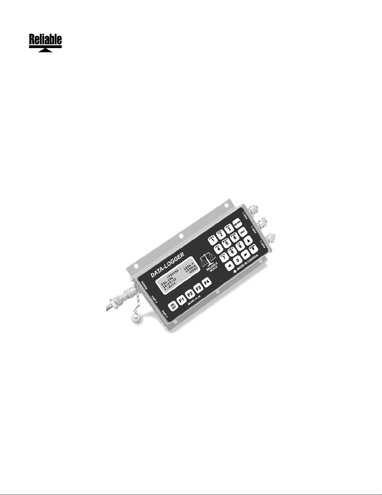
DATA-LOGGER
WIRELINE DATA-LOGGER
USER MANUAL
Rev. 1.70
Serial Number:___________________
© 1996-2008, Reliable Scale Corporation
Reliable Scale Corporation
520 Moraine Road N.E.
Calgary, Alberta, Canada
Tel:1-800-419-1189
(403) 272-8784
Fax: (403) 273-9818
E-mail: info@reliablescale.com
Web: http://www.reliablescale.com
Page 2

Reliable Scale Corporation
1. Contents
1. Contents.................................................................................................................2
2. Capabilities.............................................................................................................3
2.1 Features...........................................................................................................................3
3. Physical Layout......................................................................................................4
4. Basic Operation......................................................................................................5
4.1 Log Data ..........................................................................................................................7
4.2 Resume Logging............................................................................................................10
4.3 Delete Data....................................................................................................................11
4.4 View Job Information .....................................................................................................13
4.5 Plot Chart.......................................................................................................................14
4.6 Print Data.......................................................................................................................16
5. Configuration........................................................................................................ 18
5.1 Set Date.........................................................................................................................19
5.2 Set Time.........................................................................................................................21
5.3 Configure Ports..............................................................................................................23
5.3.1 Show Port Function.................................................................................................24
5.3.2 Set Port Function.....................................................................................................25
5.3.3 Set Port Speed........................................................................................................26
5.3.4 Set Port Format.......................................................................................................28
5.3.5 Port Test..................................................................................................................30
5.4 Set Depth Units..............................................................................................................31
5.5 Plot Delay.......................................................................................................................32
5.6 Set Password.................................................................................................................33
6. Troubleshooting.................................................................................................... 35
7. Sample Chart ....................................................................................................... 36
8. Sample Log..........................................................................................................37
9. Limited Warranty..................................................................................................38
Model DL-04 DATA-LOGGER
User Manual
Page 2 of 38 Rev. 1.70
Page 3

Reliable Scale Corporation
2. Capabilities
The Model DL-04 DATA-LOGGER is a versatile tool designed to record line
load, line speed and tool depth on Wireline trucks.
This new technology offers secure data recovery and reduces chances of operator
error and improves record keeping. The result is an improved profit picture.
DL-04 stores data accurately without interfering with the operator’s normal
The
activities.
DL-04 monitors the truck’s digital weight indicator, depth meter and line speed
The
meter as often as every 2 seconds and stores the information securely in memory.
This allows the manager to review very closely the details of each job.
2.1 Features
• Lists job description, operator ID, job date
• Each record includes record number, line load, line speed, depth, and time of
day
• Stores up to 113,825 records (over 63 hours of continuous recording at 2 second
log intervals)
• Reads data at 2 second to 99 second intervals
• Support for 115,200 bps serial transfers
• XON/XOFF flow control for serial transfers
Model DL-04 DATA-LOGGER
User Manual
Page 3 of 38 Rev. 1.70
Page 4
Reliable Scale Corporation
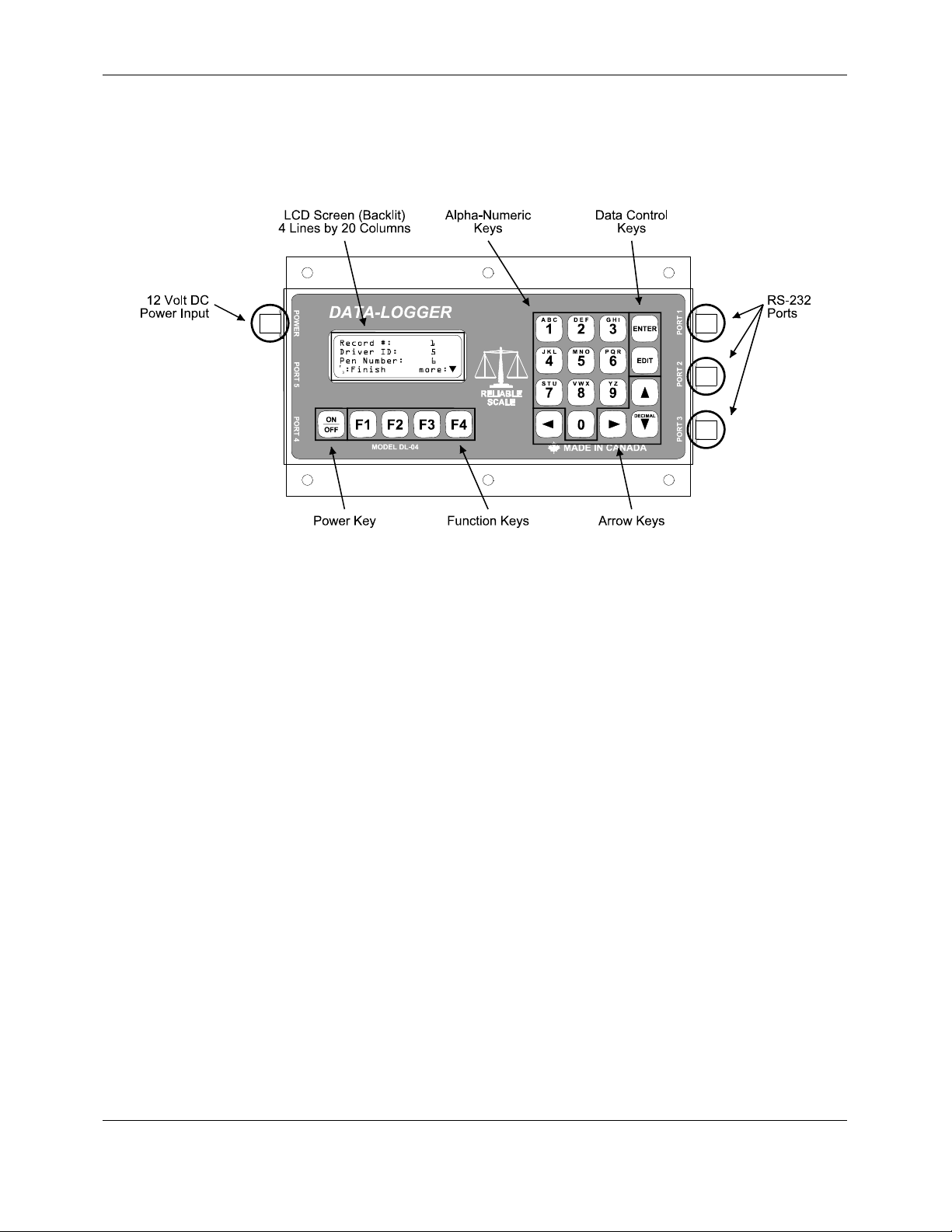
3. Physical Layout
• 12 Volt DC Power Input - 4 pin male military style connector (P/N: PT02A84P).
• LCD Screen - displays instruction and status messages to the operator.
• Alphanumeric Keys - operator keys in information.
• Data Control Keys - for Entering and Editing data.
• RS-232 Ports - 4 pin female military style connectors (P/N: PT02A8-4S) to
connect devices to the
DL-04. Example: Digital Scale, Personal Computer, Line
speed indicator.
• Arrow Keys - to scroll through menus and stored information.
• Function Keys - to issue commands; keys are assigned different functions as
listed on the LCD screen.
• Power Key - to turn the
DL-04 on and off.
Model DL-04 DATA-LOGGER
User Manual
Page 4 of 38 Rev. 1.70
Page 5
Reliable Scale Corporation
4. Basic Operation
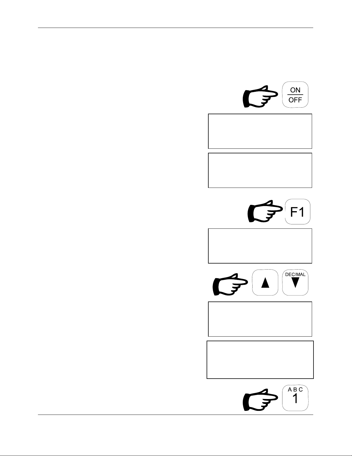
1. Press the
ON/OFF key until text appears.
Screen shows the serial number and the
software version.
The next screen shows date & time for
operator verification with local time
zones.
2. Press F1 to continue.
Screen shows the first two options
available from the Main Menu.
3. Use the UP and DOWN arrow keys to
RELIABLE SCALE
DL-04 DATA-LOGGER
S/N: 9903148
Version 1.60
RELIABLE SCALE
DL-04 DATA-LOGGER
1999-03-29 14:09:23
F1: Continue
MAIN MENU
1 Log Data
2 Resume Logging
Select # more:T
scroll through all the options.
MAIN MENU
3 Delete Data
4 View Data
Select # more:S
MAIN MENU
5 Plot Chart
6 Print Data
Select # more:
S
4. Select the option you wish to use.
Example:
Model DL-04 DATA-LOGGER
User Manual
1 Log Data
Page 5 of 38 Rev. 1.70
Page 6

Reliable Scale Corporation
5. When an process has been completed,
the
DL-04 will return to the Main Menu.
MAIN MENU
1 Log Data
2 Resume Logging
Select # more:T
Model DL-04 DATA-LOGGER
User Manual
Page 6 of 38 Rev. 1.70
Page 7
Reliable Scale Corporation
4.1 Log Data
The chief function of the
DL-04 is the Log Data process.
The screen prompts the operator through the necessary steps, issuing
instructions as required. Once the operator initiates a job, each record is
saved automatically for future transfer and analysis.
Once logging has begun, the screen is updated every log interval with
the latest log information. This maintains a record of:
• Tool Depth with units
• Line Speed with units
• Entry Time
• Line Load with units
• Entry Number (max. 113,825)
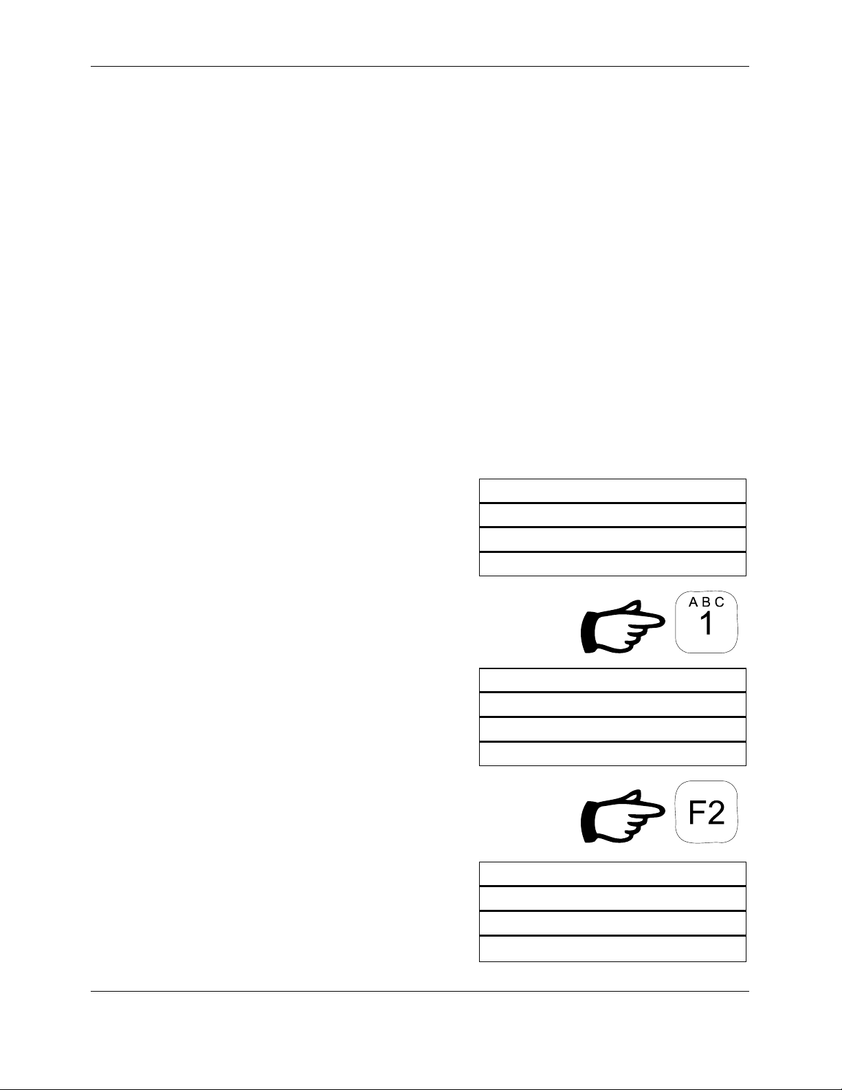
1. From the Main Menu, select Log
Data.
MAIN MENU
1 Log Data
2 Resume Logging
Select # more:T
Operator is prompted for required
information starting with Well Name
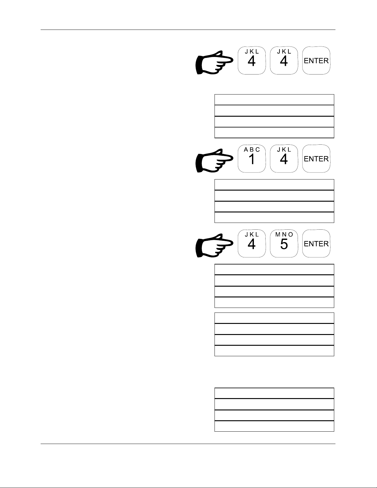
2. Key in the Well name.
Example: K14 If letters are used press
to enter alpha mode
F2
The screen will change slightly
Model DL-04 DATA-LOGGER
User Manual
Page 7 of 38 Rev. 1.70
Well Name:
F
: Alpha
2
F
: Quit
4
ENTR: Accept
Well Name:
F
: Accept alpha
2
f: Next position
Page 8
Reliable Scale Corporation
3. Press the number and arrow
keys to scroll through the
letters shown at the top of the
keys.
4. Use F2 to exit alpha mode and the
screen will return to normal
5. Input numbers normally
6. Well Number is next. Follow the
same procedure as for Well Name.
7. Key in Well Number.
Example:
45
Well Name:
K
F
: Alpha
2
F
: Quit
4
ENTR: Accept
Well Number:
F
: Alpha
2
F
: Quit
4
ENTR: Accept
Well Number:
8. Wireline Job Type is next. Follow
the same procedure as for Well
Name.
9. Key in Wireline Job Type.
Example:
COMPLETION
Model DL-04 DATA-LOGGER
User Manual
Page 8 of 38 Rev. 1.70
45
F
: Alpha
2
F
: Quit
4
ENTR: Accept
Wireline Job Type:
F
: Alpha
2
F
: Quit
4
ENTR: Accept
Wireline Job Type:
COMPLETION
F
: Alpha
2
F
: Quit
4
ENTR: Accept
Page 9
Reliable Scale Corporation
10. Job Operator is next. Follow the
same procedure as for Well Name.
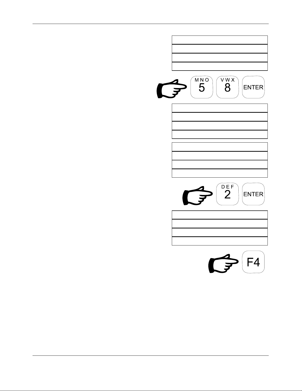
11. Key in Job Operator.
Example:
58
Log Interval is next. Intervals from 2
seconds to 99 seconds between
records are available.
12. Key in the Interval.
Job Operator:
F
: Alpha
2
F
: Quit
4
ENTR: Accept
Job Operator:
58
F
: Alpha
2
F
: Quit
4
ENTR: Accept
Log Interval(s):
Min: 2s Max: 99s
F
: Quit ENTR: Accept
4
Example:
2
The DL-04 begins reading data every
2 seconds.
13. Logging can be interrupted by
pressing
F4.
LOGGING. . .
256.42m 122m/m
10:23:10 4990kg
F
: Quit 000085
4
Model DL-04 DATA-LOGGER
User Manual
Page 9 of 38 Rev. 1.70
Page 10
Reliable Scale Corporation
4.2 Resume Logging
If a job has been interrupted for some reason, it can be resumed using
the Resume Logging process. Only the last job in memory can be
resumed. If there are no jobs in memory, this process cannot be used.
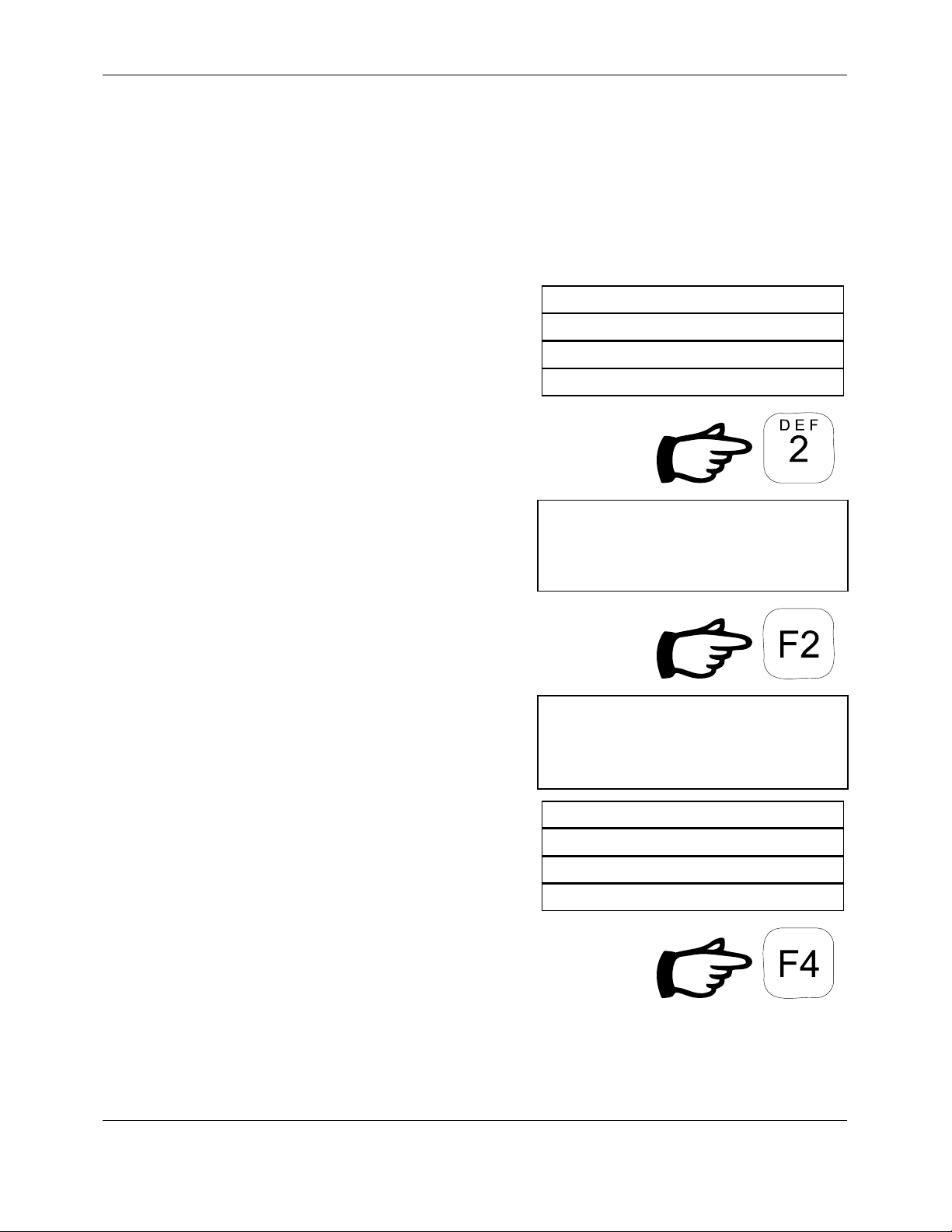
1. From the Main Menu, select Resume
Logging.
MAIN MENU
1 Log Data
2 Resume Logging
Select # more:T
The operator is asked to confirm the
resume operation.
2. Press F2 to confirm resumption.
3. The DL-04 Resumes logging
4. Logging can be interrupted by
LOGGING. . .
Resume Job # 3?
F
: Confirm
2
F
: Cancel
4
Resuming Job #: 3
LOGGING. . .
256.42m 122m/m
10:23:10 4990kg
F
: Quit 000085
4
pressing
Model DL-04 DATA-LOGGER
User Manual
F4.
Page 10 of 38 Rev. 1.70
Page 11
Reliable Scale Corporation
4.3 Delete Data
After the records have been plotted (see section 4.5 on page 14) or
transferred to a computer (see section 4.6 on page 16), clear the
DL-04
memory using the Delete Records option. Jobs should be deleted after
each day to make room for new ones and to eliminate confusion.
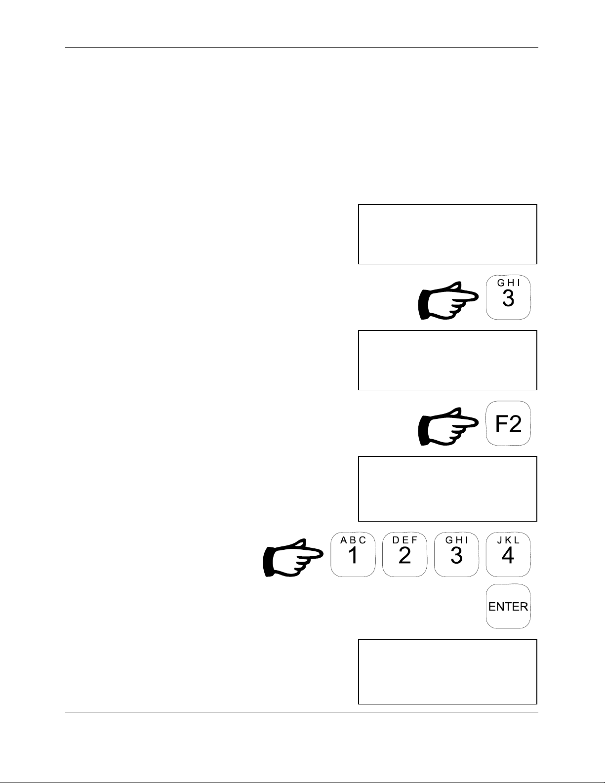
1. From the Main Menu, select Delete
Data.
The operator is asked to confirm the
delete operation.
MAIN MENU
2 Resume Logging
3 Delete Data
Select # more:T
F
: Confirm
2
Delete data
F
: Cancel
4
Delete data
2. Press F2 to Delete Records.
A password is required. The factory
default password is
5.4 on page 31 to change password.
1234. See section
3. Enter the
password.
When the password is entered, * 's are
displayed for security.
Model DL-04 DATA-LOGGER
User Manual
Page 11 of 38 Rev. 1.70
Enter password:
Enter password:****
Page 12

Reliable Scale Corporation
If a valid password has been entered,
the records are deleted and the status is
displayed on the screen.
Deleting data
Data DELETED
Model DL-04 DATA-LOGGER
User Manual
Page 12 of 38 Rev. 1.70
Page 13

Reliable Scale Corporation
4.4 View Job Information
Job information in the
DL-04 memory can be viewed on screen without
transferring or deleting it.
1. From the Main Menu, select View Job
Info.
If there is more than one job in memory,
the user will be prompted for the job
number.
2. Enter job number to view.
3. The selected job information is
displayed. Use the
keys to scroll through the information.
UP and DOWN arrow
4. To quit viewing, press F4.
MAIN MENU
3 Delete Data
4 View Job Info.
Select # more:T
VIEW JOBS
Job to View? (3)
F
: Quit
4
VIEW JOBS
Job # 3
Job Description:
F
: Quit more:T
4
Model DL-04 DATA-LOGGER
User Manual
Page 13 of 38 Rev. 1.70
Page 14

Reliable Scale Corporation
4.5 Plot Chart
Data saved in the
the form of a chart (Line Pull and Depth vs. Time). Connect the
DL-04 can be transferred to a printer or computer in
DL-04
to the printer or computer with the proper cables & hardware. Be sure
the printer/computer is ready to receive the data. The default serial port
configuration for the
DL-04 is 9600 baud, 8 data bits, no parity, 1 stop
bit.
Plotting a job does not remove it from the
DL-04’s memory. Records
are stored permanently in memory and can only be removed by using
the Delete Data option (see section 4.3, on page 11). Data transfer can
be done as many times as desired before deletion.
Note: The DL-04 has been configured for use with an Epson FX-880
printer with an RS-232 serial interface. Other compatible printers should
function, but proper operation is not guaranteed.
1. From the Main Menu, select Plot Chart.
MAIN MENU
5 Plot Chart
6 Print Data
Select # more:T
If there is more than one job in memory,
the user will be prompted for the job
number.
2. Enter job number to plot.
3. During data transfer, the number of the
entry currently being plotted is
displayed.
Model DL-04 DATA-LOGGER
User Manual
Page 14 of 38 Rev. 1.70
PLOT CHART
Job to Print? (3)
F
: Quit
4
PLOT CHART
Plotting record: 457
F
: Quit
4
Page 15

Reliable Scale Corporation
4. To quit printing, press F4.
Model DL-04 DATA-LOGGER
User Manual
Page 15 of 38 Rev. 1.70
Page 16

Reliable Scale Corporation
4.6 Print Data
Data saved in the
historical storage and analysis. Connect the
DL-04 must be transferred to a host computer for
DL-04 to the computer with
the proper cables & hardware. Be sure your computer is ready to
receive the records. The default serial port configuration for the
DL-04 is
9600 baud, 8 data bits, no parity, 1 stop bit. A standard terminal
program such as Procomm or HyperTerminal can be used for this
procedure (see your terminal program manual for details).
Transferring jobs to computer does not remove them from the
DL-04’s
memory. Records are stored permanently in memory and can only be
removed by using the Delete Data option (see section 4.3, on page 11).
Data transfer can be done as many times as desired before deletion.
1. From the Main Menu, select Print Data.
MAIN MENU
6 Plot Chart
5 Print Data
Select # more:T
If there is more than one job in memory,
the user will be prompted for the job
number.
2. Enter job number to print.
3. During data transfer, the number of the
entry currently being printed is
displayed.
Model DL-04 DATA-LOGGER
User Manual
Page 16 of 38 Rev. 1.70
PRINT DATA
Job TO Print? (3)
F
: Quit
4
PRINT DATA
Printing record: 457
F
: Quit
4
Page 17

Reliable Scale Corporation
4. To quit printing, press F4.
Model DL-04 DATA-LOGGER
User Manual
Page 17 of 38 Rev. 1.70
Page 18

Reliable Scale Corporation
5. Configuration
Some operating features of the DL-04 can be modified to suit the
equipment being used. Other parameters such as the date and time need
to be set in order to make accurate logs. All parameters are set from the
Configuration Menu.
1. From the Main Menu, select
Configuration.
2. Screen shows first two items of the
Configuration Menu. Use the
DOWN arrow keys to scroll through all
the options.
UP and
3. To return to the Main Menu, select Exit
Configuration.
MAIN MENU
6 Pint Data
7 Configuration
Select # more:S
CONFIGURATION MENU
1 Set Date
2 Set Time
Select # more:S
CONFIGURATION MENU
3 Configure Ports
4 Set Depth Units
Select # more:S
CONFIGURATION MENU
6 Set Password
7 Exit Configuration
Select # more:S
Model DL-04 DATA-LOGGER
User Manual
Page 18 of 38 Rev. 1.70
Page 19

Reliable Scale Corporation
5.1 Set Date
The current date can be seen when the
DL-04 is turned on. It is
important that this be set correctly in order to provide accurate log
information. If the date needs to be changed, it is done using the Set
Date process from the Configuration Menu.
1. From the Configuration Menu, select
Set Date.
2. Key in the year. Use four digits.
Example:
1999
CONFUGIRATION MENU
1 Set Date
2 Set Time
Select # more:T
SET DATE
Enter year:
F
: Quit
4
3. Key in the month. (1 to 12)
Example:
2
4. Key in the day. (1 to 31)
Example:
12
Model DL-04 DATA-LOGGER
User Manual
SET DATE
Enter month:
F
: Quit
4
SET DATE
Enter day:
F
: Quit
4
Page 19 of 38 Rev. 1.70
Page 20

Reliable Scale Corporation
The new date is displayed before
returning to the Configuration Menu.
5. To quit, press F4.
SET DATE
Date set to:
1999-02-12
Model DL-04 DATA-LOGGER
User Manual
Page 20 of 38 Rev. 1.70
Page 21

Reliable Scale Corporation
5.2 Set Time
The current time can be seen when the
DL-04 is turned on. It is
important that this be set correctly in order to provide accurate log
information. If the time needs to be changed, it is done using the Set
Time process from the Configuration Menu.
1. From the Configuration Menu, select
Set Time.
CONFUGIRATION MENU
1 Set Date
2 Set Time
Select # more:T
2. Key in the hour. (0 to 23)
Example:
14
SET TIME
Enter hour(24):
F
: Quit
4
3. Key in the minute. (0 to 59)
Example:
25
4. Key in the second. (0 to 59)
Example:
50
Model DL-04 DATA-LOGGER
User Manual
SET TIME
Enter minute:
F
: Quit
4
SET TIME
Enter second:
F
: Quit
4
Page 21 of 38 Rev. 1.70
Page 22

Reliable Scale Corporation
The new time is displayed before
returning to the Configuration Menu.
5. To quit, press F4.
SET TIME
Time set to:
14:25:50
Model DL-04 DATA-LOGGER
User Manual
Page 22 of 38 Rev. 1.70
Page 23

Reliable Scale Corporation
5.3 Configure Ports
The ports on the
DL-04 can be assigned to different devices to suit
individual applications. It is recommended however, that the default
port settings be used. They are:
• Port 1 - Computer/Printer
• Port 2 - Counter
• Port 3 - Weight Indicator
1. From the Configuration Menu, select
Configure Ports.
2. Screen shows first items of the Port
Config Menu. Use the
UP and DOWN
arrow keys to scroll through all the
options.
3. To return to the Configuration Menu,
select Exit Port Config.
CONFIGURATION MENU
2 Set Time
3 Configure Ports
Select # more:S
PORT CONFIG MENU
1 Show Port Function
2 Set Port Function
Select # more:S
PORT CONFIG MENU
3 Set Port Speed
4 Set Port Format
Select # more:S
CONFIGURATION MENU
5 Port Test
6 Exit Port Config
Select # more:S
Model DL-04 DATA-LOGGER
User Manual
Page 23 of 38 Rev. 1.70
Page 24

Reliable Scale Corporation
5.3.1 Show Port Function
The current port assignments can be seen by using the Show Port
Function option in the Port Config Menu. This can be a useful
troubleshooting tool if device communications problems arise.
1. From the Port Config Menu, select
Show Port Function
2. Screen shows first Port Functions. Use
the
UP and DOWN arrow keys to scroll
through the list.
3. To quit, press F4.
PORT CONFIG MENU
1 Show Port Function
2 Set Port Function
Select # more:S
PORT FUNCTIONS
PC Port: 1
Counter Port: 2
F
: Quit more:S
4
PORT FUNCTIONS
Weight Port 3
Printer Port 1
F
: Quit more:S
4
Model DL-04 DATA-LOGGER
User Manual
Page 24 of 38 Rev. 1.70
Page 25

Reliable Scale Corporation
5.3.2 Set Port Function
The current port assignments can be changed using the Set Port
Function option in the Port Config Menu. It is recommended that the
default port assignments be used.
1. From the Port Config Menu, select Set
Port Function
2. Key in the port to be changed.
Example: 1
3. Select the function.
Example: 1:PC
PORT CONFIG MENU
1 Show Port Function
2 Set Port Function
Select # more:S
SET PORT FUNCTION
Enter port number:
F
: Quit more:S
4
Select Function:
1:PC 2:Printer
3:Scale 4:Counter
4. To quit, press F4.
Model DL-04 DATA-LOGGER
User Manual
SET PORT FUNCTION
Port: 1
Function: PC
Page 25 of 38 Rev. 1.70
Page 26

Reliable Scale Corporation
5.3.3 Set Port Speed
Using the Set Port Speed option, the port baud rates can be set to
accommodate the needs of the device connected to it. It is important
that this setting is correct for proper device interfacing.
Supported Baud Rates
1200
2400
4800
9600
19,200
38,400
115,200
1. From the Port Config Menu, select Set
Port Speed.
2. Key in the port to be changed.
Example: 1
3. Key in the baud rate.
Example: 9600
PORT CONFIG MENU
3 Set Port Speed
4 Set Port Format
Select # more:S
SET PORT SPEED
Enter port number:
F
: Quit more:S
4
SET PORT SPEED
Enter port 1 speed:
F
: Quit more:S
4
Model DL-04 DATA-LOGGER
User Manual
Page 26 of 38 Rev. 1.70
Page 27

Reliable Scale Corporation
4. To quit, press F4.
SET PORT FUNCTION
Port: 1
Speed: 9600 baud
Model DL-04 DATA-LOGGER
User Manual
Page 27 of 38 Rev. 1.70
Page 28

Reliable Scale Corporation
5.3.4 Set Port Format
Using the Set Port Format option, the word length and parity
parameters for a port can be set to accommodate the needs of the
device connected to it. It is important that these settings are correct for
proper device interfacing.
Supported Word Lengths
7
8
1. From the Port Config Menu, select
Show Port Function
2. Key in the port to be changed.
Example: 1
3. Key in the word length.
Example: 8
PORT CONFIG MENU
3 Set Port Speed
4 Set Port Format
Select # more:S
SET PORT FORMAT
Enter port number:
F
: Quit more:S
4
SET PORT FORMAT
Enter word length:
F
: Quit more:S
4
Model DL-04 DATA-LOGGER
User Manual
Page 28 of 38 Rev. 1.70
Page 29

Reliable Scale Corporation
4. Choose the parity setting.
Example: 5:None
5. To quit, press F4.
Select Parity:
1:Even 2:Odd
3:Mark 4:Space
5:None
SET PORT FORMAT
Port: 1
Format: 8,N,1
Model DL-04 DATA-LOGGER
User Manual
Page 29 of 38 Rev. 1.70
Page 30

Reliable Scale Corporation
5.3.5 Port Test
Proper port operation can be tested using the Test Port Function option
in the Port Config Menu. This function should not be used when
connected to the measurement devices as they can be damaged. This
can be a useful troubleshooting tool if device communications
problems arise and should only by used by trained personnel. A test
string will be transmitted by each port using its current settings.
1. From the Port Config Menu, select Port
Test
2 To quit, press F4.
PORT CONFIG MENU
5 Port Test
6 Exit Port Config
Select # more:S
Testing Ports.
F
: Quit more:S
4
Model DL-04 DATA-LOGGER
User Manual
Page 30 of 38 Rev. 1.70
Page 31

Reliable Scale Corporation
5.4 Set Depth Units
As the Depth Counter does not provide unit information to the DL-04,
the user must specify the depth and time units to used for logging.
1. From the Configuration Menu, select
Set Depth Units.
2. Key in the depth units.
Example:
1:meters
5. Key in the depth units.
Example:
1:minutes
Configuration MENU
3 Configure Ports
4 Set Depth Units
Select # more:T
SET UNITS
Select Depth Units:
1:meters 2:feet
SET UNITS
Select Depth Units:
Depth Units: meters
SET UNITS
Select Time Units:
1:minutes 2:seconds
Model DL-04 DATA-LOGGER
User Manual
SET UNITS
Select Time Units:
Time Units: minutes
Page 31 of 38 Rev. 1.70
Page 32

Reliable Scale Corporation
5.5 Plot Delay
In order to allow the printer to keep up with the data transfer, a time
delay is used. After each line of the chart has been transferred, the
waits for a specific amount of time. This length of time is
04
DL-
determined by the Plot Delay setting and is measured in milliseconds.
1. From the Configuration Menu, select
Plot Delay.
2. The current Plot Delay setting is
displayed and the user in prompted for
the new setting.
3. Key in the new Port Delay setting.
Example: 1500mS
CONFIGURATION MENU
5 Plot Delay
6 Set Password
Select # more:S
SET DELAY
Current Delay: 1100
New Delay:
F
: Quit
4
SET DELAY
Current Delay: 1100
New Delay: 1500
F
: Quit
4
4. To quit, press F4.
Model DL-04 DATA-LOGGER
User Manual
SET DELAY
Plot Delay: 1500mS
Page 32 of 38 Rev. 1.70
Page 33

Reliable Scale Corporation
5.6 Set Password
A password is required to delete data from the DL-04. If a password
other than the factory default (
1234) is desired, it can be changed using
the Set Password process.
1. From the Configuration Menu, select
Set Password.
2. Key in the old password.
When the password is entered, * 's are
displayed for security.
4. Key in the new password.
When the password is entered, * 's are
Configuration MENU
3 Configure Ports
4 Set Password
Select # more:T
CHANGE PASSWORD
Old Password:
F
: Quit
4
CHANGE PASSWORD
New Password:
F
: Quit
4
displayed for security.
5. Key in the new password again to
confirm it.
When the password is entered, * 's are
displayed for security.
Model DL-04 DATA-LOGGER
User Manual
Page 33 of 38 Rev. 1.70
CHANGE PASSWORD
Confirm Password:
F
: Quit
4
CHANGE PASSWORD
New Password Saved.
F
: Quit
4
Page 34

Reliable Scale Corporation
6. To quit, press F4.
Model DL-04 DATA-LOGGER
User Manual
Page 34 of 38 Rev. 1.70
Page 35

Reliable Scale Corporation
6. Troubleshooting
1. The DL-04 won’t turn on.
Ensure that the power connector is properly plugged in and is supplying
12VDC. Pin A of the power connector is positive, pin B is negative.
2. When transferring data to the computer, nothing happens or else the data
looks like garbage.
Check the cable connections to the computer and make sure the terminal
program is properly configured. The default is 9600 baud, 8 data bits, no
parity, 1 stop bit.
Model DL-04 DATA-LOGGER
User Manual
Page 35 of 38 Rev. 1.70
Page 36

Reliable Scale Corporation
7. Sample Chart
The following is a sample chart produced by the DL-04.
Reliable Scale Corporation
DL-04 Wireline Data-Logger
Log Reoprt
Report Date: 1999-10-22
Job#: 4
Start Entry: 50
Well Name: TEST WELL
Well Number: 452
Wireline Job Type: TEST
Job Operator: JOHN SMITTH
Job Date: 1999-10-22
Start Time: 08:23:35
End Time: 08:25:33
Log Interval: 2s
* = Line Pull 0 lb = 0% 5818 lb = 100% + = Depth 0 m = 0% 38.54 m = 100%
0% 25% 50% 75% 100%
|-----------------------------|-----------------------------|-----------------------------|-----------------------------|
08:23:35|*+ | | | |
08:23:37| *+ | | | |
08:23:39| +* | | | |
08:23:41| + * | | | |
08:23:43| + * | | | |
08:23:45| + * | | | |
08:23:47| +* | | | |
08:23:49| *+ | | | |
08:23:51| * + | | | |
08:23:53| * + | | | |
08:23:55| * + | | | |
08:23:57| * + | | | |
08:23:59| * |+ | | |
08:24:01| * | + | | |
08:24:03| * | + | | |
08:24:05| * | + | | |
08:24:07| * | + | | |
08:24:09| * | + | | |
08:24:11| * | + | | |
08:24:13| * | + | | |
08:24:15| *| + | | |
08:24:17| * |+ | |
08:24:19| |* | + | |
08:24:21| | * | + | |
08:24:23| | * | + | |
08:24:25| | * | + + | |
08:24:27| | * | + | |
08:24:29| | * | + | |
08:24:31| | * | + | |
08:24:33| | * | + | |
08:24:35| | * | + | |
08:24:37| | * | + | |
08:24:39| | * | + | |
08:24:41| | * | +| |
08:24:43| | * | |+ |
08:24:45| | * | | + |
08:24:47| | * | | + |
08:24:49| | * | | + |
08:24:51| | * | | |
08:24:53| | * | |+ |
08:24:55| | * | + | |
08:24:57| | * | + | |
08:24:59| | * | + | |
08:25:01| | * | + | |
08:25:03| | *| + | |
08:25:05| | |* | |
08:25:07| | | * + | |
08:25:09| | | * + | |
08:25:11| | | * + | |
08:25:13| | | * + | |
08:25:15| | | * + |
08:25:17| | | * | + |
08:25:19| | | * | + |
08:25:21| | | * | + |
08:25:23| | | * | + |
08:25:25| | | * | + |
08:25:27| | | |* + |
08:25:29| | | | * + |
08:25:31| | | | * + |
08:25:33| | | | + *
|-----------------------------|-----------------------------|-----------------------------|-----------------------------|
0% 25% 50% 75% 100%
60 entries plotted
Model DL-04 DATA-LOGGER
User Manual
Page 36 of 38 Rev. 1.70
Page 37

Reliable Scale Corporation
8. Sample Log
The following is a sample log gathered by the DL-04. Each column has
a fixed number of characters and is separated by a comma (,). The
columns are organized as follows:
1. Log entry
2. Memory location
3. Log time
4. Line Load
5. Line depth
6. Line speed
Job#: 1
Job Date: 1999-02-25
Log Interval: 2s
Start Entry: 1
Job Description: WELL01
Job Operator: BILL
1, 1, 15:28:46, 5377kg, 200.00m, 0m/m
2, 2, 15:28:48, 5376kg, 200.00m, 0m/m
3, 3, 15:28:50, 5376kg, 200.48m, 33m/m
4, 4, 15:28:52, 5376kg, 202.20m, 49m/m
5, 5, 15:28:54, 5376kg, 204.15m, 68m/m
6, 6, 15:28:56, 5376kg, 206.51m, 65m/m
7, 7, 15:28:58, 5376kg, 208.77m, 61m/m
8, 8, 15:29:00, 5376kg, 210.12m, 65m/m
9, 9, 15:29:02, 5376kg, 212.24m, 54m/m
10, 10, 15:29:04, 5376kg, 214.08m, 50m/m
11, 11, 15:29:06, 5376kg, 216.15m, 48m/m
12, 12, 15:29:08, 5376kg, 218.32m, 56m/m
13, 13, 15:29:10, 5376kg, 220.61m, 71m/m
14, 14, 15:29:12, 5376kg, 222.91m, 71m/m
15, 15, 15:29:14, 5376kg, 224.43m, 66m/m
16, 16, 15:29:16, 5376kg, 226.28m, 37m/m
17, 17, 15:29:18, 5376kg, 227.32m, 37m/m
18, 18, 15:29:20, 5376kg, 228.32m, 25m/m
19, 19, 15:29:22, 5322kg, 229.02m, 26m/m
20, 20, 15:29:24, 5322kg, 230.07m, 26m/m
21, 21, 15:29:26, 5447kg, 230.69m, 41m/m
22, 22, 15:29:28, 5449kg, 232.78m, 53m/m
23, 23, 15:29:30, 5449kg, 234.64m, 71m/m
24, 24, 15:29:32, 5449kg, 237.06m, 68m/m
25, 25, 15:29:34, 5449kg, 238.57m, 22m/m
26, 26, 15:29:36, 5449kg, 238.82m, 6m/m
27, 27, 15:29:38, 5449kg, 238.87m, 1m/m
28, 28, 15:29:40, 5449kg, 238.87m, 0m/m
28 records printed
Model DL-04 DATA-LOGGER
User Manual
Page 37 of 38 Rev. 1.70
Page 38

Reliable Scale Corporation
9. Limited Warranty
This warranty applies to all new equipment manufactured by RELIABLE SCALE
CORPORATION except when otherwise specified in the Terms of Sale. Warranty is subject to
the following terms and conditions:
• All new products are warranted for a period of twelve (12) months from the date of final sale
to the end user (maximum 24 months from date of manufacture).
• RELIABLE SCALE CORPORATION shall at its option, repair or replace or refund the
purchase price, within a reasonable period of time, after being notified of the alleged defect
and after acknowledging that a defect does in fact exist.
• Warranty claims must be submitted in writing by mail, fax or email to RELIABLE SCALE
CORPORATION within the warranty period.
• This warranty does not extend to any consequential damage of other equipment, loss of use,
commercial or economic loss or inconvenience prior to or during the repair period.
• RELIABLE SCALE CORPORATION is not responsible for any damage or defects caused
by misuse, negligence, neglect, modification, improper operation, improper maintenance, or
repairs by any unauthorized persons.
• This is the sole warranty applicable to RELIABLE SCALE CORPORATION'S products, and
no RELIABLE SCALE CORPORATION employee, agent or dealer has any authority to
add to this warranty whatsoever.
• Products for warranty repair must be returned to the factory freight prepaid by the customer.
RELIABLE SCALE CORPORATION is not liable for any cost related to removal,
replacement, or shipping of the products or any other associated equipment.
Batteries supplied in or with RELIABLE SCALE CORPORATION products are NOT covered
by this warranty.
Model DL-04 DATA-LOGGER
User Manual
Page 38 of 38 Rev. 1.70
 Loading...