

Regency Panorama P42 Installation Manual
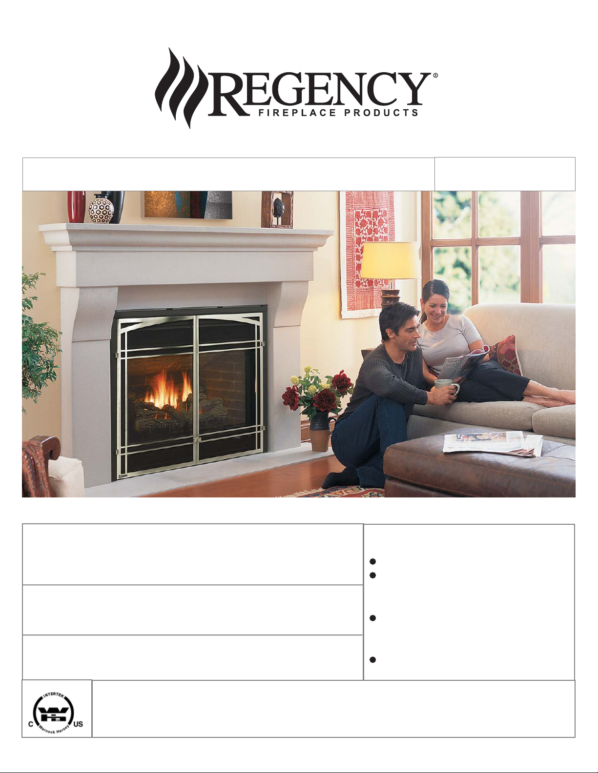
P42 Gas Fireplace
Owners &
Installation Manual
MODELS: P42-NG4 Natural Gas P42-LP4 Propane
WARNING:
If the information in these instructions are not followed exactly,
a fi re or explosion may result causing property damage,
personal injury or loss of life.
FOR YOUR SAFETY
Do not store or use gasoline or other fl ammable vapors and
liquids in the vicinity of this or any other appliance.
Installation and service must be performed by a qualifi ed
installer, service agency or the gas supplier.
Tested by:
918-523b
FPI FIREPLACE PRODUCTS INTERNATIONAL LTD. 6988 Venture St., Delta, BC Canada, V4G 1H4
Installer: Please complete the details on the back cover
and leave this manual with the homeowner.
Homeowner: Please keep these instructions for future reference.
www.regency-fi re.com
FOR YOUR SAFETY
What to do if you smell gas:
Do not try to light any appliance
Do not touch any electrical switch:
do not use any phone in your
building.
Immediately call your gas supplier
from a neighbour's phone. Follow
the gas supplier's instructions.
If you cannot reach your gas
supplier, call the fi re department.
07/30/09
WARNING
HOT GLASS
CAUSE BURNS
DO NOT TOUCH
UNTIL COOLED
NEVER
TO TOUCH GLASS
CHILDREN AND ADULTS SHOULD BE ALERTED TO
THE HAZARDS OF HIGH SURFACE TEMPERATURES,
ESPECIALLY THE FIREPLACE GLASS, AND SHOULD
ST AY AWA Y TO AVOID BURNS OR CLOTHING IGNITION.
ALLOW CHILDREN
WILL
GLASS
To the New Owner:
Congratulations!
Y ou are the owner of a state-of-the-art Gas Fireplace by FIREPLACE PRODUCTS INTERNATIONAL. The
P42 is a hand crafted appliance and has been designed to provide you with all the warmth and charm of
a wood fi replace at the fl ick of a switch. The model P42 has been approved by Warnock Hersey for both
safety and effi ciency. As it also bears our own mark, it promises to provide you with economy, comfort and
security for many trouble free years to follow. Please take a moment now to acquaint yourself with these
instructions and the many features of your Regency® Fireplace.
INFORMATION FOR MOBILE/MANUFACTURED HOMES AFTER FIRST SALE
This Regency® product has been tested and listed by Warnock Hersey as a Vented Gas Fireplace Heater to the following standards:
UL307B-1995, CAN/CGA-2.17-M91, ANSI Z21.88a-2007/CSA 2.33a-2007.
This Direct Vent System Appliance must be installed in accordance with the manufacturer's installation instructions and the Manufactured Home
Construction and Safety Standard, Title 24 CFR, Part 3280, or the current Standard of Fire Safety Criteria for Manufactured Home Installations,
Sites, and Communities ANSI/NFPA 501A, and with CAN/CSA Z240-MH Mobile Home Standard in Canada.
This appliance installation must comply with the manufacturer's installation instructions and local codes, if any. In the absence of local codes follow
the current National Fuel Gas Code, ANSI Z223.1 and the current National Electrical Code ANSI/NFPA 70 in the U.S.A., and the current CAN/CGA
B149 Gas Installation Code and the current Canadian Electrical Code CSA C22.1 in Canada.
This Regency® Mobile/Manufactured Home Listed
appliance comes factory equipped with a means to
secure the unit.
This Regency® Mobile/Manufactured Home listed
appliance comes equipped with a dedicated #8 ground
lug to which an 18 gauge copper wire from the steel
chassis ground must be attached.
This appliance may be installed in an aftermarket
permanently located, manufactured (mobile) home,
where not prohibited by local codes.
This appliance is only use with the type of gas indicated
on the rating plate. This appliance is not convertible for
use with other gases, unless a certifi ed kit is used.
2
Regency® P42-4 Zero Clearance Direct Vent Gas Fireplace

TABLE OF CONTENTS
SAFETY LABEL
Copy of Safety Decal .....................................................4
REQUIREMENTS
MA Code - CO Detector.................................................5
INSTALLATION
Important Message ......................................................6
Before You Start ............................................................6
General Safety Information............................................6
Installation Checklist ......................................................6
Manufactured Mobile Home Additional Requirements ..7
Locating Your Gas Fireplace .........................................7
Unit Specifi cations .........................................................7
Heatwave Optional Duct System Kit#946-556 .............7
Optional Hearth .............................................................7
Clearances ....................................................................8
Mantels ..........................................................................8
Mantel Leg Clearances..................................................8
Framing And Finishing ...................................................9
Top Assembly & Nailing Strips .......................................9
Venting Introduction .......................................................9
Vent Restrictor ...............................................................9
Exterior Vent Termination Requirements .....................10
Venting.........................................................................11
4” x 6-5/8” Rigid Pipe Cross Reference Chart .............12
Rigid Pipe Venting .......................................................14
Horizontal Terminations ..............................................15
Vertical Terminations ...................................................17
Installation Procedures ................................................23
High Elevation .............................................................24
Gas Line Installation ....................................................24
Gas Pipe Pressure Testing ..........................................24
Aeration Adjustment ....................................................25
Brick Panels.................................................................25
Log Set Installation ......................................................26
Standard Flush Door ...................................................27
Flush Louvers ..............................................................27
Double Screen Doors .................................................27
Optional Bay Door .......................................................28
Bay Louvers.................................................................28
Full Screen doors ........................................................29
Wiring Diagrams .........................................................32
OPERATING INSTRUCTIONS
Optional Remote Control .............................................34
Optional Wall Switch ....................................................34
Optional Wall Thermostat ...........................................34
Operating Instructions .................................................34
Lighting Procedure ......................................................34
Copy Of The Lighting Plate Instructions .....................35
MAINTENANCE
Normal Operating Sounds Of Gas Appliances ............36
Shutdown Procedure ...................................................36
First Fire ......................................................................36
Maintenance Instructions.............................................36
Gold-Plated Louvers ....................................................37
Log Replacement ........................................................37
Thermopile / Thermocouple .........................................37
Glass Replacement .....................................................37
Door Glass...................................................................37
Removing The Fan ......................................................38
Replacing The Fan ......................................................38
Removing Valve ...........................................................38
Installing Valve .............................................................39
PARTS LIST
Main Assembly ............................................................40
Burner & Log Assembly ...............................................41
Flush Door & Louvers ..................................................42
Bay Front & Louvers ....................................................43
WARRANTY
Warranty ......................................................................47
Regency® P42-4 Zero Clearance Direct Vent Gas Fireplace 3
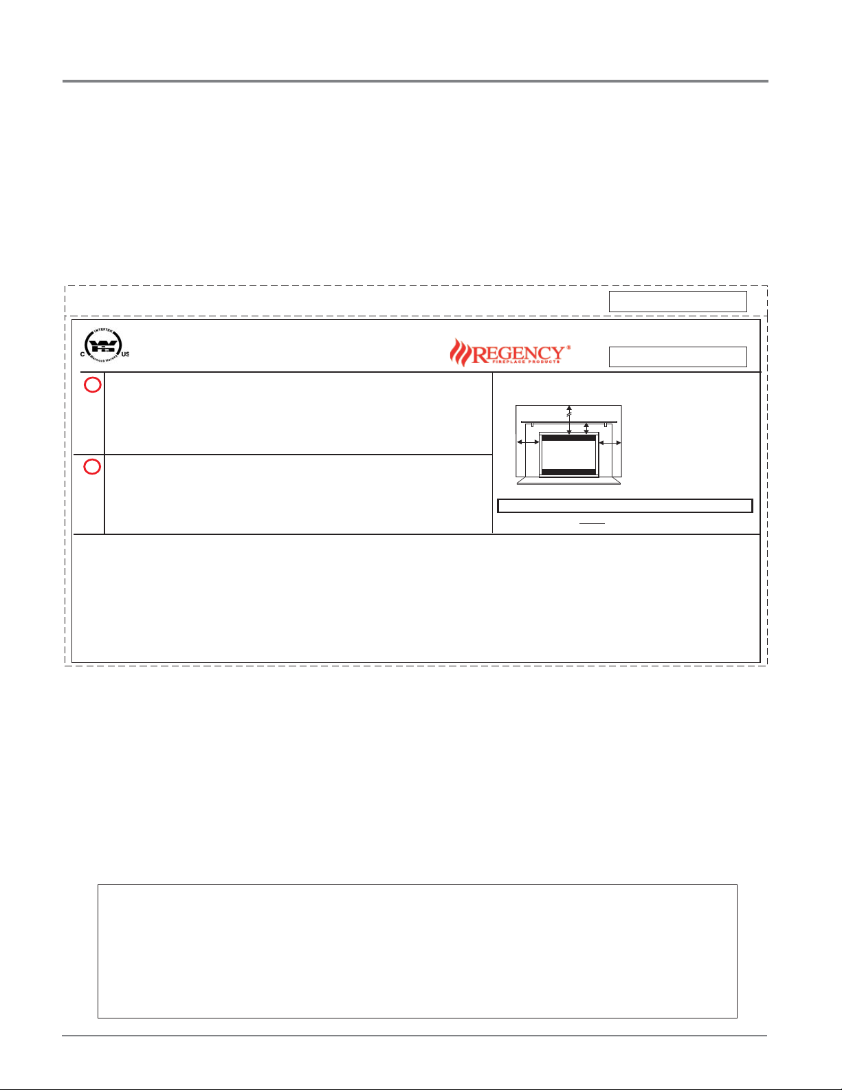
SAFETY LABEL
This is a copy of the label that accompanies each P42 Zero Clearance
Direct Vent Gas Fireplace. We have printed a copy of the contents here
for your review. The safety label is located on the front inside base of
NOTE: Regency® units are constantly being improved. Check the label
on the unit and if there is a difference, the label on the unit is the correct
one.
the unit, visible when the bottom louver is open.
COPY OF SAFETY DECAL FOR P42
DUPLICATE SERIAL NO.
Listed:
VENTED GAS FIREPLACE HEATER / FOYER AU GAZ À ÉVACUATION
Certified for/Certifi e pour:
Tested to:
WN# 16461
MAY BE INSTALLED IN MANUFACTURED (MOBILE) HOMES AFTER FIRST SALE.
NATURAL GAS:
L
Minimum supply pressure
Model/Modele:
P42-NG4
Manifold pressure high
Manifold pressure low
Orifice size
Minimum input
Maximum input
Altitude
PROPANE:
L
Model/Modele:
P42-LP4
Minimum supply pressure
Manifold pressure high
Manifold pressure low
Orifice size
Minimum input
Maximum input
Altitude
This appliance must be installed in accordance with local codes, if any; if none, follow the National Fuel Gas Code, ANSI Z223.1, or Natural Gas and Propane Installation Code, CSA B149.1.
This appliancemust be installedin accordancewith the StandardCAN/CSA Z240MH, Mobile Housing,in Canada, orwith theManufactured Home Constructionand Safety Standard,Title 24CFR, Part 3280,in the UnitedStates, or
when sucha standardis not applicable,ANSI/NCSBCSA225.1/NFPA 501A,Manufactured HomeInstallations Standard orANSIA119.2 ouNFPA501C Standard forRecreational Vehicles
This applianceis only foruse with the typeof gas indicatedon the ratingplate and may beinstalled in anaftermarket, permanently located,manufactured (mobile) home wherenot prohibited bylocal codes. Seeowner's manual for
details.
Installer l'appareilselon lescodes ou règlementslocaux, ou,en l'absence detels règlements,selon les codesd'installation ANSIZ223.1, NationalFuel Gas Codeou CSA-B149.1en vigueur.
Installer l'appareilselon la normeCAN/CSA-Z240, Série MM, Maisonmobiles ou CAN/CSA-Z240VC, Véhicules de camping,ou la norme24 CFR Part3280, Manufactured Home Constructionand Safety Standard.Si ces normes
ne sontpas pertinentes,utilisez la normeANSI/NCSBCSA225.1/NFPA 501A,Manufactured HomeInstallations Standard, ouANSIA119.2 ouNFPA501C Standard forRecreational Vehicles.
Cet appareildoit être utilizeuniquement avec letype de gazindiqué sur laplaque signalétique. Cetappareil peut êtreinstallé dans unemaison préfabriquée oumobile (É.-U. seulement)installée à demeuresi les règlementslocaux
le permettent.Voir lanotice del'utilisateur pour plusde renseignements.Cet appareil nepeut pasêtre utilisé avecd'autres gazsauf si unetrousse deconversion certifiée estfournie.
This ventedgas fireplaceheater is notfor usewith air filters. Ne pasutiliser defiltre à airavec cefoyer au gazà évacuation.
For usewith glassdoors certified withthe applianceonly
Fan (Part # 600-915) Optional Bay Window (Part # 603-930) Option: HeatWave Kit # 946-556
Electrical supply / Électrique 115VAC, 1.13 A, 60Hz.
Model P42-LP4
VENTED GAS FIREPLACE HEATER - NOT FOR USE WITH SOLID FUELS. /
é
CGA-2-17-M91, ANSI Z21.88a-2007 / CSA 2.33a-2007
Model P42-NG4
CANADA and U.S.A.
5" (1.25 kPa)
WC
3.8" (0.94 kPa)
WC
0.9" (0.22 kPa)
WC
# 33 DMS
17500 (5.13 Kwh)
B
tu/h
35000 (10.25Kwh)
B
tu/h
0-4500 (0-1372 m)
ft/pi
11" (2.74 kPa)
WC
10" (2.49 kPa)
WC
2.9" (0.72 kPa)
WC
# 50 DMS
17500 (5.13 Kwh)
B
tu/h
35000 (10.25Kwh)
B
tu/h
0-4500 (0-1372 m)
ft/pi
Pour utilisationuniquement avecles portes enverre certifiéesavec l'appareil
APPAREIL FONCTIONNANT AU NATURAL GAZ
CONCU POUR ETRE POELE:
Pression d'allimentation minimum
Pression à la tubulure d' chappement lev e
Pression à la tubulure d' chappement basse
Grandeur de l'injecteur
D bit Calorifique minimum selon
é
D bit Calorifique maximum selon
é
l'altitude
APPAREIL FONCTIONNANT AU PROPANE
CONCU POUR ETRE POELE:
Pression d'allimentation minimum
Pression à la tubulure d' chappement lev e
Pression à la tubulure d' chappement basse
Grandeur de l'injecteur
D bit Calorifique minimum selon
é
D bit Calorifique maximum selon
é
l'altitude
NE PAS UTILISER AVEC DU COMBUSTIBLE SOLIDE.FOYER AU GAZ À ÉVACUATION -
Modéle P42-NG4
ééé
é
Modéle P42-LP4
ééé
é
DO NOT REMOVE THIS LABEL / NE PAS ENLEVER CETTE ÉTIQUETTE
Ceiling
36"
6"
Wall
(See Instruction Manual for Detailed Instructions)
DOOR SEAL: Please check that the door is properly sealed
The "Bay Louvers" be used with the Bay Glass optionMUST
FPI Fireplace Products International Ltd.
Made in Canada/ Fabrique au Canada
307
Serial No./ No de serie
307
Minimum Clearances to Combustibles
/Degagement Minimum
De Materiaux Combustibles
0" clearance to combustibles from:
A
Delta, BC, Canada
Top, sides, bottom and rear of unit
Mantel Clearances from Louver:
Wall
6"
A) Min. 7" (177mm)
Max. Alcove Clearances:
Depth 36" (914mm), Width 52" (1321mm),
Height 90" (2286mm)
918-501a
For the State of Massachusetts, installation and repair must be done by a plumber or gasfi tter licensed in the Commonwealth of
Massachusetts.
For the State of Massachusetts, fl exible connectors shall not exceed 36 inches in length.
For the State of Massachusetts, the appliances individual manual shut-off must be a t-handle type valve.
The State of Massachusetts requires the installation of a carbon monoxide alarm in accordance with NFPA 720 and a CO alarm
with battery back up in the same room where the gas appliance is installed.
4
Regency® P42-4 Zero Clearance Direct Vent Gas Fireplace

REQUIREMENTS
MA Code - CO Detector
(for the State of Massachusetts only)
5.08: Modifications to NFPA-54, Chapter 10
(2) Revise 10.8.3 by adding the following additional requirements:
(a) For all side wall horizontally vented gas fueled equipment installed in every dwelling, building or structure used in whole or in part for
residential purposes, including those owned or operated by the Commonwealth and where the side wall exhaust vent termination is less than
seven (7) feet above finished grade in the area of the venting, including but not limited to decks and porches, the following requirements shall
be satisfied:
1. INSTALLATION OF CARBON MONOXIDE DETECTORS. At the time of installation of the side wall horizontal vented gas fueled
equipment, the installing plumber or gasfitter shall observe that a hard wired carbon monoxide detector with an alarm and battery back-up is
installed on the floor level where the gas equipment is to be installed. In addition, the installing plumber or gasfitter shall observe that a battery
operated or hard wired carbon monoxide detector with an alarm is installed on each additional level of the dwelling, building or structure
served by the side wall horizontal vented gas fueled equipment. It shall be the responsibility of the property owner to secure the services of
qualified licensed professionals for the installation of hard wired carbon monoxide detectors
a. In the event that the side wall horizontally vented gas fueled equipment is installed in a crawl space or an attic, the hard wired carbon
monoxide detector with alarm and battery back-up may be installed on the next adjacent floor level.
b. In the event that the requirements of this subdivision can not be met at the time of completion of installation, the owner shall have a period of
thirty (30) days to comply with the above requirements; provided, however, that during said thirty (30) day period, a battery operated carbon
monoxide detector with an alarm shall be installed.
2. APPROVED CARBON MONOXIDE DETECTORS. Each carbon monoxide detector as required in accordance with the above provisions
shall comply with NFPA 720 and be ANSI/UL 2034 listed and IAS certified.
3. SIGNAGE. A metal or plastic identification plate shall be permanently mounted to the exterior of the building at a minimum height of eight
(8) feet above grade directly in line with the exhaust vent terminal for the horizontally vented gas fueled heating appliance or equipment. The
sign shall read, in print size no less than one-half (1/2) inch in size, "GAS VENT DIRECTLY BELOW. KEEP CLEAR OF ALL
OBSTRUCTIONS".
4. INSPECTION. The state or local gas inspector of the side wall horizontally vented gas fueled equipment shall not approve the installation
unless, upon inspection, the inspector observes carbon monoxide detectors and signage installed in accordance with the provisions of 248 CMR
5.08(2)(a)1 through 4.
(b) EXEMPTIONS: The following equipment is exempt from 248 CMR 5.08(2)(a)1 through 4:
1. The equipment listed in Chapter 10 entitled "Equipment Not Required To Be Vented" in the most current edition of NFPA 54 as adopted by
the Board; and
2. Product Approved side wall horizontally vented gas fueled equipment installed in a room or structure separate from the dwelling, building or
structure used in whole or in part for residential purposes.
(c) MANUFACTURER REQUIREMENTS - GAS EQUIPMENT VENTING SYSTEM PROVIDED. When the manufacturer of Product
Approved side wall horizontally vented gas equipment provides a venting system design or venting system components with the equipment, the
instructions provided by the manufacturer for installation of the equipment and the venting system shall include:
1. Detailed instructions for the installation of the venting system design or the venting system components; and
2. A complete parts list for the venting system design or venting system.
(d) MANUFACTURER REQUIREMENTS - GAS EQUIPMENT VENTING SYSTEM NOT PROVIDED. When the manufacturer of a
Product Approved side wall horizontally vented gas fueled equipment does not provide the parts for venting the flue gases, but identifies
"special venting systems", the following requirements shall be satisfied by the manufacturer:
1. The referenced "special venting system" instructions shall be included with the appliance or equipment installation instructions; and
2. The "special venting systems" shall be Product Approved by the Board, and the instructions for that system shall include a parts list and
detailed installation instructions.
(e) A copy of all installation instructions for all Product Approved side wall horizontally vented gas fueled equipment, all venting instructions,
all parts lists for venting instructions, and/or all venting design instructions shall remain with the appliance or equipment at the completion of
the installation.
Regency® P42-4 Zero Clearance Direct Vent Gas Fireplace 5
INSTALLATION
IMPORTANT MESSAGE
SAVE THESE
INSTRUCTIONS
The P42-NG/P42-LP Direct Vent Fireplace must
be installed in accordance with these instructions.
Carefully read all the instructions in this manual
fi rst. Consult the "authority having jurisdiction" to
determine the need for a permit prior to starting
the installation. It is the responsibility of the
installer to ensure this fi replace is installed in
compliance with manufacturers instructions and
all applicable codes.
BEFORE YOU ST ART
Safe installation and operation of this appliance
requires common sense, however, we are
required by the Canadian Safety Standards
and ANSI Standards to make you aware of
the following:
INSTALLATION AND REPAIR
SHOULD BE DONE BY AN
AUTHORIZED SERVICE PERSON.
THE APPLIANCE SHOULD BE
INSPECTED BEFORE USE AND
AT LEAST ANNUALLY BY A
PROFESSIONAL SERVICE PERSON.
MORE FREQUENT CLEANING MA Y
BE REQUIRED DUE TO EXCESSIVE
LINT FROM CARPETING, BEDDING
MA TERIAL, ETC. IT IS IMPERA TIVE
THAT CONTROL COMP ARTMENTS,
BURNERS AND CIRCULATING
AIR PASSAGEWAYS OF THE
APPLIANCE BE KEPT CLEAN.
DUE TO HIGH TEMPERATURES, THE
APPLIANCE SHOULD BE LOCA TED
OUT OF TRAFFIC AND AW AY FROM
FURNITURE AND DRAPERIES.
WARNING: FAILURE TO INSTALL
THIS APPLIANCE CORRECTL Y WILL
VOID YOUR WARRANTY AND MAY
CAUSE A SERIOUS HOUSE FIRE.
CHILDREN AND ADULTS SHOULD
BE ALERTED TO THE HAZARDS OF
HIGH SURFACE TEMPERATURES,
ESPECIALLY THE FIREPLACE
GLASS, AND SHOULD STAY AWAY
TO AVOID BURNS OR CLOTHING
IGNITION.
YOUNG CHILDREN SHOULD BE
CAREFULLY SUPERVISED WHEN
THEY ARE IN THE SAME ROOM AS
THE APPLIANCE.
CLOTHING OR OTHER FLAMMABLE
MATERIAL SHOULD NOT BE PLACED
ON OR NEAR THE APPLIANCE.
GENERAL SAFETY
INFORMATION
1) The appliance installation must conform
with local codes or, in the absence of local
codes, with the current Canadian or National
Gas Codes, CAN1-B149 or ANSI Z223.1
Installation Codes.
2) The appliance when installed, must be
electrically grounded in accordance with
local codes, or in the absence of local codes
with the current National Electrical Code,
ANSI/NFPA 70 or CSA C22.1 Canadian
Electrical Code.
3) See general construction and assembly
instructions. The appliance and vent should
be enclosed.
4) This appliance must be connected to the
specifi ed vent and termination cap to the
outside of the building envelope. Never vent
to another room or inside a building. Make
sure that the vent is fi tted as per Venting
instructions.
5) Inspect the venting system annually for
blockage and any signs of deterioration.
6) Venting terminals shall not be recessed into
a wall or siding.
7) Any safety glass removed for servicing
must be replaced prior to operating the
appliance.
8) To prevent injury , do not allow anyone who
is unfamiliar with the operation to use the
fi replace.
9) Wear gloves and safety glasses for protection
while doing required maintenance.
10) Be aware of electrical wiring locations in
walls and ceilings when cutting holes for
termination.
11) Under no circumstances should this
appliance be modifi ed. Parts that have to be
removed for servicing should be replaced
prior to operating this appliance.
12) Installation and any repairs to this appliance
should be done by an authorized service
person. A professional service person should
be called to inspect this appliance annually.
Make it a practice to have all of your gas
appliances checked annually.
13) Do not slam shut or strike the glass door.
14) Under no circumstances should any solid
fuels (wood, paper, cardboard, coal, etc.)
be used in this appliance.
15) The appliance area must be kept clear and
free of combustible materials, (gases and
other fl ammable vapours and liquids).
Emissions from burning wood or gas could
contain chemicals known to the State of
California to cause cancer, birth defects or
other reproductive harm.
INSTALLATION
CHECKLIST
1) Locate appliance, refer to the following
sections:
a) Locating Your Gas Fireplace
b) Clearances
c) Mantels
d) Mantels Legs Clearance
e) Framing and Finishing
2) Assemble Top Facing Support and Side
Nailing Strips, see the "Top Assembly
& Nailing Strips" section. NOTE: must
be done before installing unit into
fi replace.
3) Install venting, refer to the "Venting"
section.
4) Make gas and electrical connections. Test
the pilot. Must be as per diagram. See the
"Pilot Adjustment" section.
5) Test Gas Pressure. Refer to the "Gas Pipe
Pressure Testing" section.
6) Install standard and optional features.
Refer to the following sections where
applicable:
a. Brick Panels
b. Log Set
c. Standard Flush Door
d. Flush Louvers
e. Double Screen Door
f. Bay Door
g. Bay Louvers
h. Full Screen Front
i. Remote Control
j. Wall Switch
k. Wall Thermostat
11) Final check.
Before leaving this unit with the customer,
the installer must ensure that the appliance is
fi ring correctly and operation fully explained
to customer.
6
Regency® P42-4 Zero Clearance Direct Vent Gas Fireplace
INSTALLATION
This includes:
1) Clocking the appliance to ensure the correct
fi ring rate (rate noted on label 35,000 Btu/h)
after burning appliance for 15 minutes.
2) If required, adjusting the primary air to
ensure that the fl ame does not carbon.
First allow the unit to burn for 15-20 min.
to stabilize.
CAUTION: Any alteration to the product that
causes sooting or carboning that results
in damage is not the responsibility of the
manufacturer.
MANUFACTURED
MOBILE HOME
ADDITIONAL
REQUIREMENTS
1) Ensure that structural members are not cut
or weakened during installation.
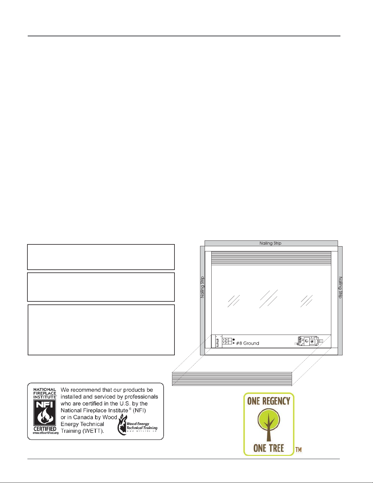
2) Ensure proper grounding using the #8
ground lug provided. See the "Wiring
Diagram" section.
LOCATING YOUR
GAS FIREPLACE
1) When selecting a location for your stove,
ensure that the clearances outlined on this
page are met.
2) Provide adequate clearances for
servicing.
3) The appliance must be installed on a fl at,
solid, continuous surface (e.g. wood, metal,
concrete). This may be the fl oor, or raised up
on a platform to enhance its visual impact.
If the appliance is going to be installed
on carpeting, combustible linoleum tile or
other combustible material other than wood
fl ooring, the appliance must be installed on a
metal or wood panel extending the full width
and depth of the appliance.
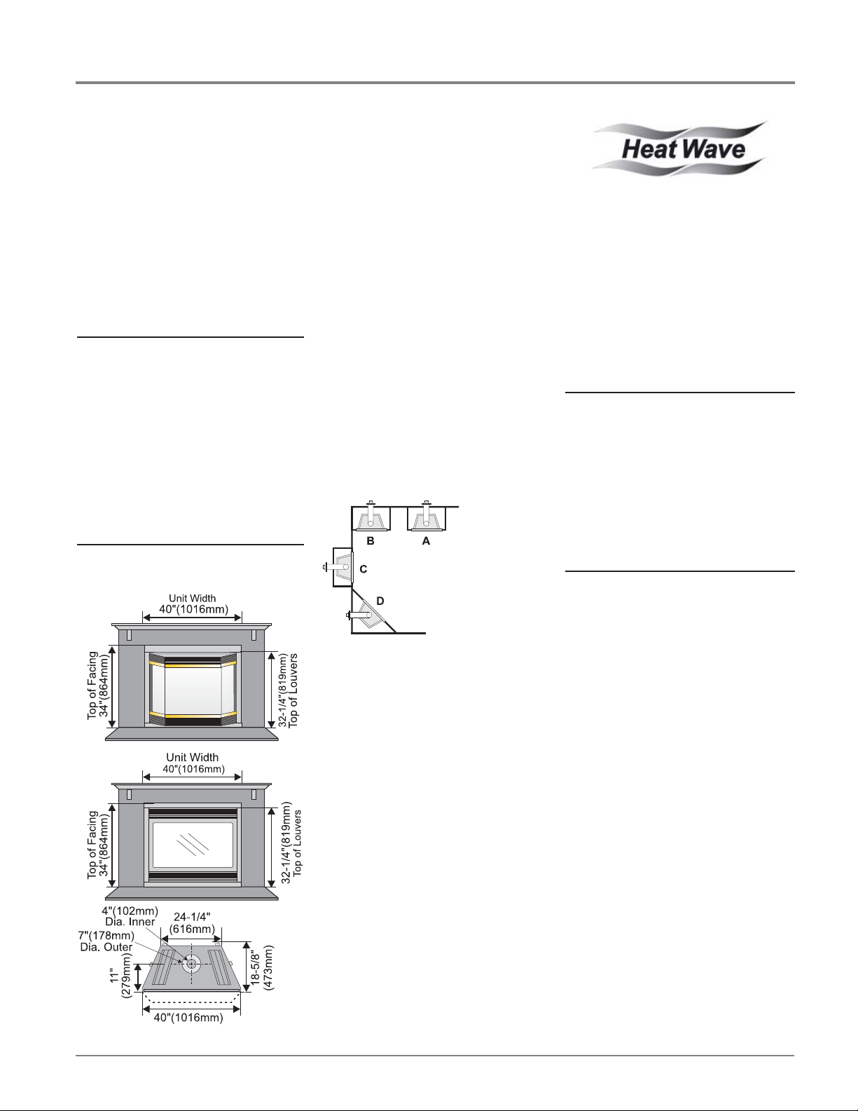
4) The P42 Direct Vent Gas Fireplace can be
installed in a recessed position or framed out
into the room as in A, B, C, D. See Diagram
1.
Diagram 1
HEATWAVE
OPTIONAL DUCT
SYSTEM KIT
#946-556
The HeatWave Air Duct Kit increases the
effectiveness of your fi replace by dispersing
warm air from the fi replace to remote locations in
the same room or other rooms in your home.
Up to two kits may be installed on the fi replace.
Please Note: Only 1 HeatWave kit may be
operated at one time. This includes the internal
blower option as well.
OPTIONAL
HEAT RELEASE KIT
#946-570
The Heat Release Kit expels warm air from
the fi replace to the outside of the building,
allowing the fi replace to be operated with less
heat entering the room. The kit may be used on
either the left or right side.
UNIT SPECIFICATIONS
A) Flat on Wall
B) Flat on Wall Corner
C) Recessed into
Wall/Alcove
D) Corner
5) This appliance is Listed for bedroom
installations when used with a Listed Millivolt
Thermostat. Some areas may have further
requirements, check local codes before
installation.
6) The P42 Direct Vent Gas Fireplace is
approved for alcove installations, which
meet the clearances listed on this page.
7) We recommend that you plan your installation
on paper using exact measurements for
clearances and fl oor protection before
actually installing this appliance. Have an
authorized inspector, dealer, or installer
review your plans before installation.
Note: For vent terminations see the
"Exterior Vent T ermination Locations"
section.
HEARTH
A hearth is not mandatory , but is recommended
for aesthetics and for added safety.
Regency® P42-4 Zero Clearance Direct Vent Gas Fireplace 7
INSTALLATION
CLEARANCES
The clearances listed below are Minimum
distances unless otherwise stated:
A major cause of chimney related fi res is
failure to maintain required clearances (air
space) to combustible materials. It is of the
greatest importance that this fi replace and
vent system be installed only in accordance
with these instructions.
Clearance to Combustibles from:
Back 0" (0mm)
Side 0" (0mm)
Floor 0" (0mm)
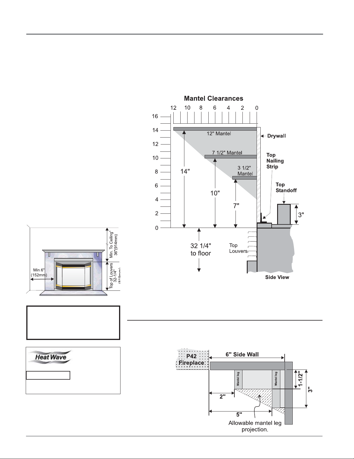
Minimum Clearance from Louver to:
Mantel min. 7" (177mm)
Ceiling 36" (914mm) from top
of louvers
Side Wall 6" (152mm)
Vent 1-1/2" (38mm) Flex
1-1/4" (32mm) Rigid Pipe
Alcove Clearances:
Max. Depth 36" (914mm)
Min. Width 52" (1321mm)
Min. Height 90" (2286mm)
MANTELS
Because of the extreme heat this fi replace emits, the mantel clearances are critical.
Combustible mantel clearances from louver are shown in the diagram below.
Note: A non-combustible mantel may be installed at a lower height if the framing is made
of metal studs covered with a non-combustible board.
WARNING
Fire hazard is an extreme risk
if these clearances are
not adhered to.
The HeatWave Duct Kit
and the Heat Release
Kit have different
clearance and framing
Heat Release Kit
8
requirements, check
the HeatWave and Heat
Release manual for
details.
This drawing is to scale at 1:6 (one inch = 6 inches)
Mantel can be installed anywhere in shaded area using the above scale for units with the Flush
Front and with the optional Bay Front.
Note: Ensure the paint that is used on the mantel and the facing is "heat resistant" or the
paint may discolour.
MANTEL LEG CLEARANCES
Combustible mantel leg clearances as per diagram below:
Maximum
1-1/2" projection at 2"
minimum clearance.
Regency® P42-4 Zero Clearance Direct Vent Gas Fireplace
Position of Top Facing Support
for material depth of 3/4” to 1-1/2"
Top Facing
Support
INSTALLATION
FRAMING AND
FINISHING
1) Determine the total thickness of facing
material (ie. drywall plus ceramic tiles) to
allow the fi nished surface to be fl ush with
the front of the unit. Total facing thickness
can vary from 1/2" (13mm) to 1-1/4" (32mm)
thick.
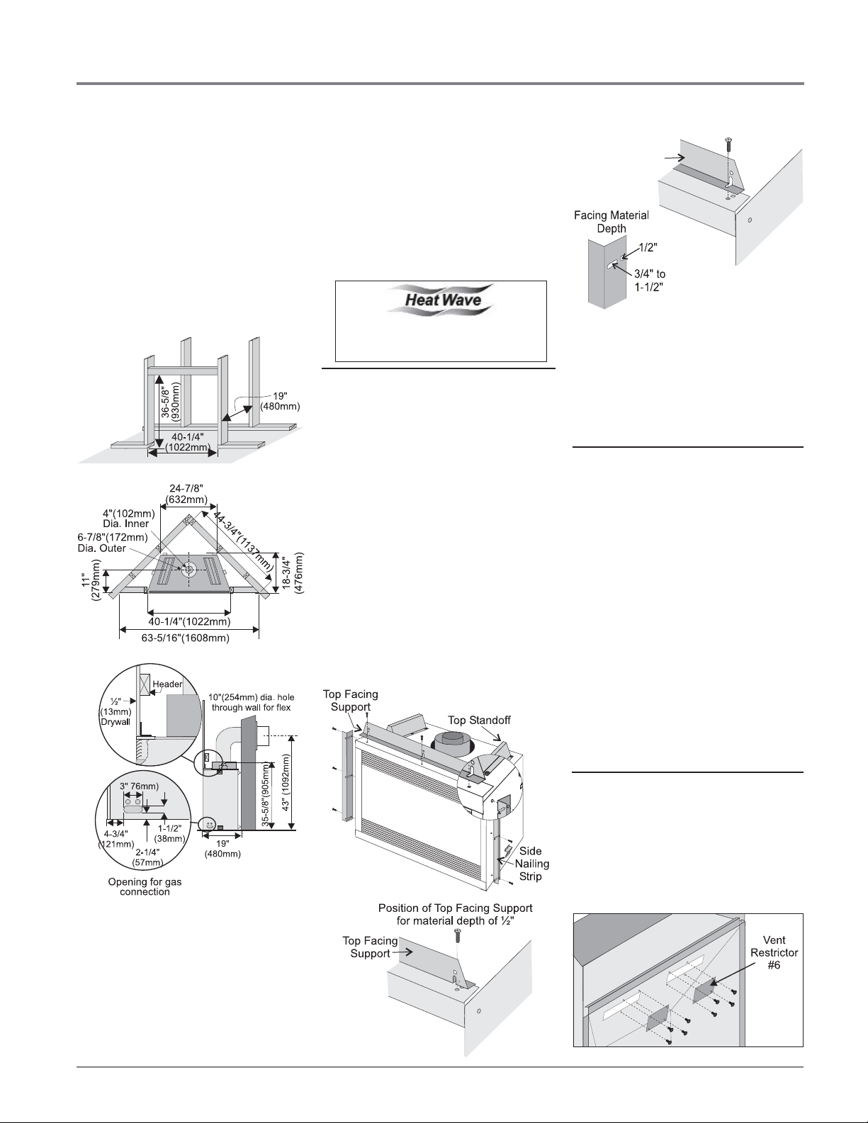
2) Frame in the enclosure for the unit with
framing material. The framed opening for
the assembled kit is 36-5/8" high x 40-1/4"
wide x 19" deep (930mm H x 1022mm W
x 483mm D). See Diagram 1.
Diagram 1
5) The unit does not have to be completely
enclosed in a chase. The clearance on top
of the unit from the top standoffs is 0" so
combustible building materials can be laid
directly on top of the standoffs. You must
maintain these clearances from the vent
to combustible materials: Flex Termination
clearance 1-1/2" (38mm), Simpson Dura-Vent
clearance or (1-1/4" (32mm). Combustible
materials can be laid against the side and
back standoffs and the fi replace base.
The HeatWave Duct Kit has different
clearance and framing requirements,
check the HeatWave manual for details.
TOP ASSEMBLY &
NAILING STRIPS
The T op Facing Support and Side Nailing Strips
must be correctly positioned and attached before
the unit is slipped into position.
1) The top standoffs are shipped installed.
2) The Top Facing Support and the 2 Side
Nailing Strips can be installed at different
depths depending on the width of your facing.
Match the depths of the top facing support
and the side nailing strips.
a) Mount Top Facing Support using the 3
supplied screws into the 3 pre-punched
screw holes on the top front of the unit.
See Diagrams 2 & 3 for the proper
position of the Top Facing Support for
the various material depths.
Diagram 3
Diagram 4
b) Mount the Side Nailing Strip using the 3
supplied screws into the 3 screw holes
or slots (diagram 4) on the side of the
unit and repeat for the other side. Use
the hole for a 1/2" (13mm) thick facing
material and the slot for a range of
thickness from 3/4" to 1-1/2" (25mm to
38mm).
VENTING
INTRODUCTION
The P42 uses the "balanced fl ue" technology
Co-Axial system. The inner liner vents products
of combustion to the outside while the outer
liner draws outside combustion air into the
combustion chamber thereby eliminating the
need to use heated room air for combustion and
losing warm room air up the chimney.
Note: These flue pipes must not be
connected to any other appliance.
The gas appliance and vent system must be
vented directly to the outside of the building,
and never be attached to a chimney serving a
separate solid fuel or gas burning appliance.
Each direct vent gas appliance must use it's own
separate vent system. Common vent systems
are prohibited.
Note: 43" (1092mm) is the minimum height
for fl ex termination and Rigid Pipe
terminations.
3) For exterior walls, insulate the enclosure to
the same degree as the rest of the house,
apply vapour barrier and drywall, as per
local installation codes. (Do not insulate
the fi replace itself.)
4) The top louvers must not be closer than
36" (914mm) to the ceiling.
Regency® P42-4 Zero Clearance Direct Vent Gas Fireplace 9
Diagram 1
Diagram 2
VENT RESTRICTOR
A vent restrictor may be required. Check
the diagrams in the "Rigid Pipe Venting
Arrangements" section to determine if the #6
restrictor is needed for your vent confi guration.
If required, attach the 2 piece #6 restrictor
using 4 screws per piece to the inside top of
the fi rebox.
INSTALLATION
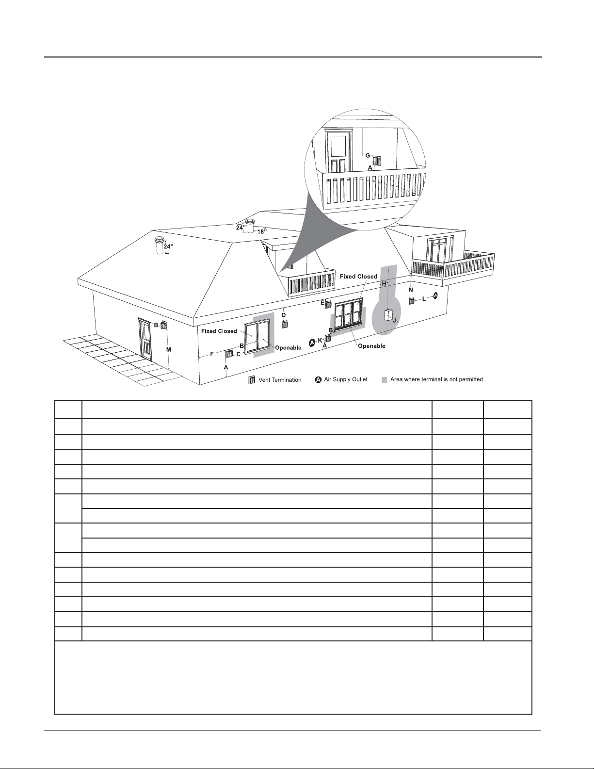
EXTERIOR VENT TERMINATION REQUIREMENTS
1
Minimum Clearance Requirements
A Clearance above grade, veranda, porch, deck, or balcony 12"(30cm) 12"(30cm)
B Clearance to window or door that may be opened 12"(30cm) 9" (23cm)
C Clearance to permanently closed window **
D Vertical clearance to ventilated soffi t located above the terminal within a horizontal distance of 2 feet (61cm) 18"(46cm) 18"(46cm)
E Clearance to unventilated soffi t 15"(38cm) 15"(38cm)
F Clearance to outside corner: with AstroCap Termination Cap. 6"(15cm) 6"(15cm)
Clearance to outside corner: with all other approved Termination Caps. 13"(33cm) 13"(33cm)
G Clearance to inside corner: with AstroCap Termination Cap 6"(15cm) 6"(15cm)
Clearance to inside corner: with all other approved Termination Caps. 12"(30cm) 12"(30cm)
H Clearance to each side of center line extended above meter/regulator assembly 36"(90cm)
J Clearance to service regulator vent outlet 36"(90cm) *
K Clearance to non-mechanical air supply inlet to building or the combustion air inlet to any other appliance 12"(30cm) 9" (23cm)
L Clearance to a mechanical air supply inlet 72"(1.8m) 36"(90cm)
M Clearance above paved sidewalk or a paved driveway located on public property 84"(2.1m)
N Clearance under veranda, porch, deck, or balcony 12"(30cm)
1
In accordance with current CSA B149.1, Natural Gas and Propane Installation Code
2
In accordance with the current ANSI Z223.1/NFPA 54, National Fuel Gas Code
┼
A vent shall not terminate directly above a sidewalk or paved driveway which is located between two single family dwellings and serves both dwellings.
‡ Permitted only if veranda, porch, deck, or balcony is fully open on a minimum of two sides beneath the fl oor.
Clearance in accordance with local installation codes and the requirements of the gas supplier
*
a
3 feet (91cm) within a height of 15 feet (4.5m) above the meter / regulator assembly
b
3 feet (91cm) above - if within 10 feet (3m) horizontally
Canada
a
┼
‡
USA
*
*
*
2
b
10
Regency® P42-4 Zero Clearance Direct Vent Gas Fireplace
INSTALLATION
VENTING
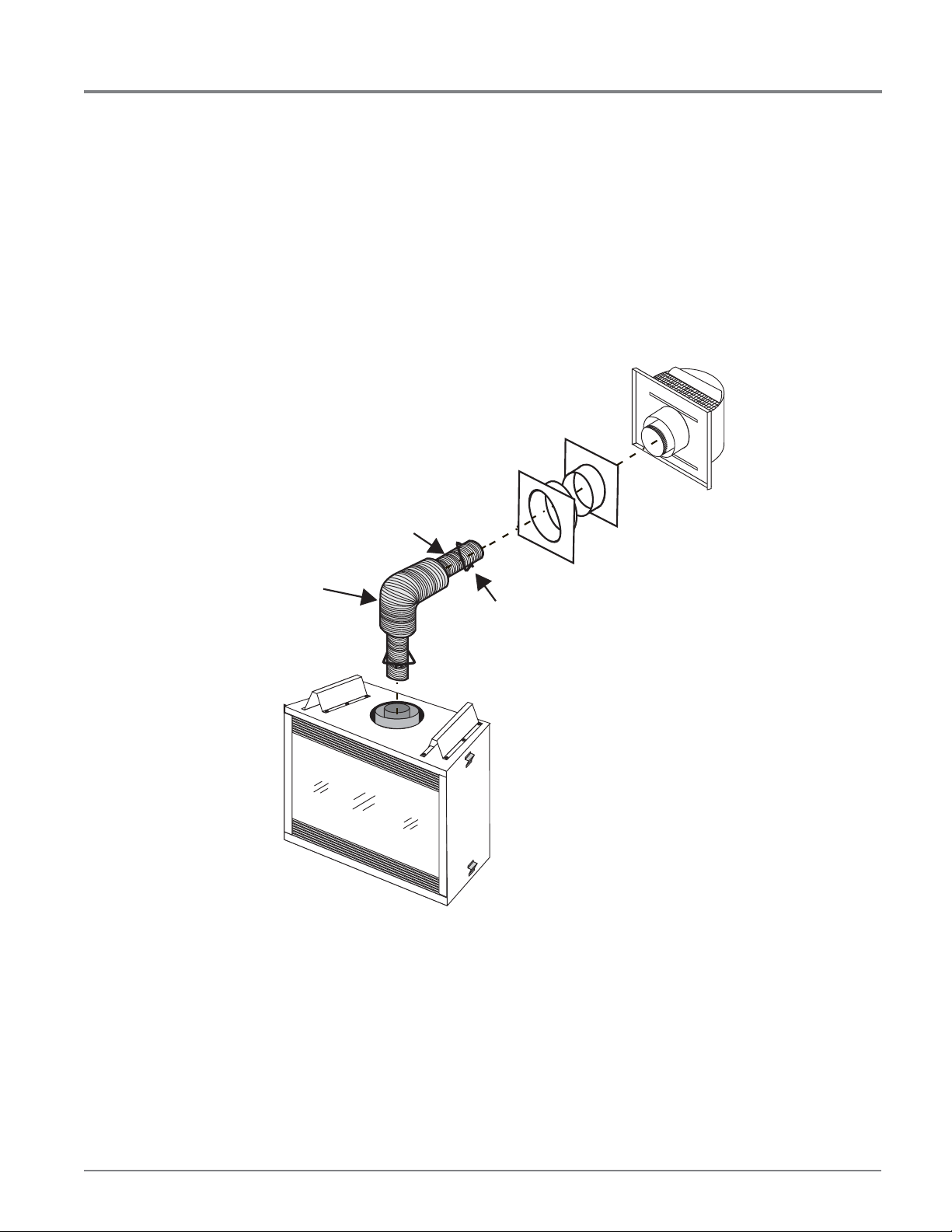
Regency® Direct Vent System (Flex) Horizontal Terminations Only
These venting systems, in combination with the P42 Direct Vent Gas
Fireplace, have been tested and listed as a direct vent heater system
by Warnock Hersey . The location of the termination cap must conform to
the requirements in the Vent Terminal Locations diagram in the "Exterior
Vent Termination Locations" section.
Regency® Direct Vent (Flex) System T ermination Kit (Part # 946-515)
includes all the parts needed to install the P42 with a maximum
run of 4 feet.
Wall Thimble (2 pc)
4" (102mm)
dia. flue pipe
6-7/8"
(173mm) dia.
Flue pipe
1) 6-7/8" dia. fl exible liner (4 ft. length)
2) 4" dia. fl exible liner (4 ft. length)
3) spring spacers (4)
4) thimble (2)
5) AstroCap termination cap (1)
6) screws (12)
7) tube of Mill Pac (1)
8) plated screws (8)
9) screws #8 x 1/2" Drill Point, stainless steel (4)
AstroCap
Termination Cap
Part #946-523/P
spring
spacer
®
If longer runs are needed, the Regency
# 946-516 includes all the parts needed to install the P42 with a
maximum 10' run.
1) 6-7/8" dia. fl exible liner (10 ft. length)
2) 4" dia. fl exible liner (10 ft. length)
3) spring spacers (7)
4) thimble (2)
5) AstroCap termination cap (1)
6) screws (12)
7) tube of Mill Pac (1)
8) plated screws (8)
9) screws #8 x 1/2" Drill Point, stainless steel (4)
Regency® P42-4 Zero Clearance Direct Vent Gas Fireplace 11
Direct Vent system (Flex)
Note:
a) Liner sections should be continuous without any joints or seams.
b) Only Flex pipe purchased from Regency® may be used for Flex
Installations.
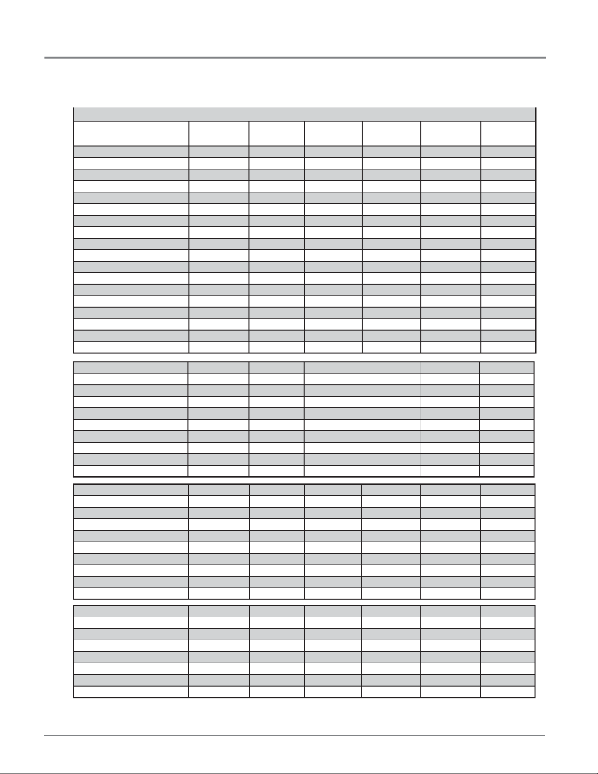
4 X 6 5/8 RIGID PIPE CROSS REFERENCE CHART
INSTALLATION
4” X 6-5/8” RIGID PIPE CROSS REFERENCE CHART
Components from different Manufacturers may not be mixed. Not All Rigid Pipe components are available directly from FPI.
Components from different Manufacturers may not be mixed. Not all rigid pipe components are available directly from Regency.
Description
6” Pipe Length-Galvanized 46DVA-06 4DT-6 N/A 4D6 SV4L6 TC-4DL6
6” Pipe Length-Black 46DVA-06B 4DT-6B N/A 4D6B SV4LB6 TC-4DL6B
7” Pipe Length-Galvanized N/A N/A 4D7 N/A N/A N/A
7” Pipe Length-Black N/A N/A 4D7B N/A N/A N/A
9” Pipe Length-Galvanized 46DVA-09 4DT-9 N/A N/A N/A N/A
9” Pipe Length-Black 46DVA-09B 4DT-9B N/A N/A N/A N/A
12” Pipe Length-Galvanized 46DVA-12 4DT-12 4D12 4D12 SV4L12 TC-4DL1
12” Pipe Length-Black 46DVA-12B 4DT-12B 4D12B 4D12B SV4LB12 TC-4DL1B
18” Pipe Length-Galvanized 46DVA-18 4DT-18 4D18 4D18 SV4LA TC-4DL18
18” Pipe Length-Black 46DVA-18B 4DT-18B 4D18B 4D18B SV4LA TC-4DL18B
24” Pipe Length-Galvanized 46DVA-24 4DT-24 4D24 4D24 SV4L24 TC-4DL2
24” Pipe Length-Black 46DVA-24B 4DT-24B 4D24B 4D24B SV4LB24 TC-4DL2B
36” Pipe Length-Galvanized 46DVA-36 4DT-36 4D36 4D36 SV4L36 TC-4DL3
36” Pipe Length-Black 46DVA-36B 4DT-36B 4D36B 4D36B SV4LB36 TC-4DL3B
48” Pipe Length-Galvanized 46DVA-48 4DT-48 4D48 4D48 SV4L48 TC-4DL4
48” Pipe Length-Black 46DVA-48B 4DT-48B 4D48B 4D48B SV4LB48 TC-4DL4B
60” Pipe Length-Galvanized 46DVA-60 4DT-60 N/A N/A N/A N/A
60” Pipe Length-Black 46DVA-60B 4DT-60B N/A N/A N/A N/A
Simpson
Direct Vent Pro
®
Selkirk
Direct Temp™
American Metal
Products®
Amerivent Direct
Metal-Fab™
Sure Seal
Security
Secure- Vent®
ICC Excel
Direct
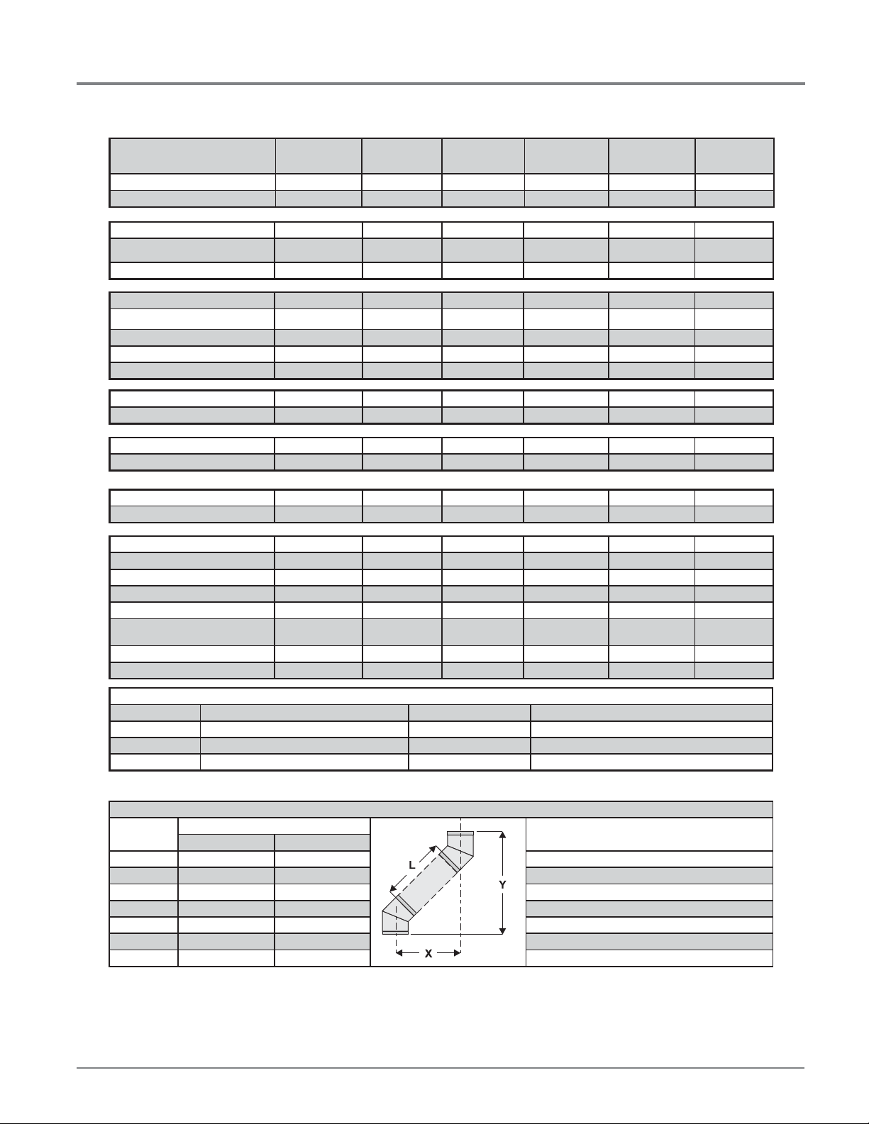
Adjustable Length 3”-10”-Galvanized N/A N/A N/A 4DAL N/A TC-4DLT
Adjustable Length 3”-10”-Black N/A N/A N/A 4DALB N/A TC-4DLTB
Adjustable Length 7”-Galvanized N/A N/A 4D7A N/A N/A N/A
Adjustable Length 7”-Black N/A N/A 4D7AB N/A N/A N/A
Extension Pipe 8-1/2”-Galvanized 46DVA-08A N/A N/A N/A N/A N/A
Extension Pipe 8-1/2”-Black 46DVA-08AB N/A N/A N/A N/A N/A
Adjustable Length 12”-Galvanized N/A N/A 4D12A N/A SV4LA12 N/A
Adjustable Length 12”-Black N/A N/A 4D12A N/A SV4LBA12 N/A
Extension Pipe 16”-Galvanized 46DVA-16A N/A N/A N/A N/A N/A
Extension Pipe 16”-Black 46DVA-16AB N/A N/A N/A N/A N/A
45º Elbow-Galvanized 46DVA-E45 4DT-EL45 4D45L N/A N/A TE-4DE45
45º Elbow-Black 46DVA-E45B 4DT-EL45B 4DT-EL45B N/A N/A TE-4DE45B
45º Elbow Swivel-Galvanized See 46DVA-E45 N/A N/A 4D45L SV4E45 N/A
45º Elbow Swivel-Black See 46DVA-E45B N/A N/A 4D45LB SV4EB45 N/A
90º Elbow-Galvanized 46DVA-E90 4DT-EL90S 4DT-EL90S N/A N/A TE-4DE90
90º Elbow-Black 46DVA-E90B 4DT-EL90SB 4DT-EL90SB N/A SV4EBR90-1 TE-4DE90B
90º Elbow, Swivel-Galvanized See 46DVA-E90 N/A N/A 4D90L SV4E90-1 N/A
90º Elbow, Swivel-Black See 46DVA-E90B N/A N/A 4D90LB SV4EB90-1 N/A
90º Starter Elbow, Swivel-Galvanized N/A N/A N/A 4D90A N/A N/A
Adaptor* N/A N/A N/A 4D90L N/A N/A
Ceiling Support N/A 4DT-CS 4DFSP 4DSP SV4SD TE-4DE45
Cathedral Support Box 46DVA-CS 4DT-CSS 4DRSB 4DRS SV4CSB TE-4DE45B
Wall Support/Band 46DVA-WS 4DT-WS/B 4DWS 4DWS SV4BM N/A
Offset Support
Wall Thimble-Black 46DVA-WT 4DT-WT 4DWT 4DWT SV4RSM TE-4DE90
Wall Thimble Support/Ceiling Support 46DVA-DC N/A N/A N/A SV4PF TE-4DE90B
Firestop Spacer 46DVA-FS 4DT-FS 4DFSP 4DFS SV4BF N/A
Trim Plate-Black N/A 4DT-TP 4DFPB 4DCP SV4LA N/A
46DVA-ES (N/A - FPI)
4DT-OS N/A N/A SV4SU N/A
12
Regency® P42-4 Zero Clearance Direct Vent Gas Fireplace
INSTALLATION
Description
Attic Insulation Shield 12” 46DVA-IS N/A@ FPI N/A 4DAIS12 N/A SV4RSA N/A
Attic Insulation Shield -
Basic Horizontal Ter mination Kit (A) Disc. 4DT-HKA 4DHTK2 4DHTKA SV-SHK N/A
Horizontal Ter mination Kit (B) 46DVA-KHA
Vertical Termination Kit Disc. 4DT-VKC 4DHTK 4DHTK SV-FK N/A
High Wind Vertical Cap 46DVA-VCH N/A N/A N/A N/A TM-4VT
High Wind Horizontal Cap 46DVA-HC N/A N/A N/A N/A TM-4DHT
Horizontal Square Ter mination Cap See
Vertical Termination Cap N/A 4DT-HVC 4DVC 4DVT SV4CGV-1 TM-4VT
Storm Collar 46DVA-08A 4DT-SC 4DSC 4DSC SV4FC TM-SC
Adjustable Flashing 0/12-6/12 N/A 4DT-ST14 4D12S 4DST14 SV4STC14 TF-4FA
Adjustable Flashing 6/12-12/12 N/A 4DT-ST36 4D36S 4DST36 SV4STC36 TF-4FB
Vinyl Siding Standoff 46DVA-VSS 4DT-VS N/A 4DVS SV4VS TM-VSS
Vinyl Siding Shield Plate N/A 4DT-VSP N/A N/A SV4VS N/A
Snorkel Termination 14” 46DVA-VCH N/A N/A N/A N/A TM-4ST14
Snorkel Termination 36” 46DVA-HC N/A N/A N/A N/A TM-4ST36
Restrictor Disk 46DVA-RD N/A N/A N/A N/A TM-4DS
Extended Vertical Termination Cap 46DVA-VCE N/A N/A N/A N/A N/A
Chimney Conversion Kit A (USA only) 46DVA-KCA N/A N/A N/A N/A TM-4CA6
Chimney Conversion Kit B (USA only) 46DVA-KCB N/A N/A N/A N/A TM-4CA7
Chimney Conversion Kit C (USA only) 46DVA-KCC N/A N/A N/A N/A TM-4CA8
Chimney Conversion Kit Masonry
(USA only)
Wall Firestop 46DVA-WFS N/A N/A N/A N/A TM-4TR
Colinear Flex Connectors 46DVA-ADF N/A N/A N/A N/A N/A
Cold Climates 36” N/A N/A 4DAIS12 N/A N/A TM-4AS
Simpson
Direct Vent Pro
(Changed Components)
46DVA-HC 4DT-HHC 4DHC 4DHT SV4CHC-1 TM-4HT
46DVA-KMC N/A N/A N/A N/A N/A
®
Selkirk
Direct Temp™
4DT-HKB 4DHTK1 4DHTKB SV-HK N/A
American Metal
Products®
Amerivent Direct
Metal-Fab™
Sure Seal
Security
Secure- Vent®
ICC Excel
Direct
FPI
946-506/P Vent Guard (Optional) for AstroCap 946-205 Vinyl Siding Shield for Riser Vent Terminal
510-994 Rigid Pipe Adaptor (Must use with all rigid piping) 946-208/P Vent Guard (Optional) for Riser Vent Terminal
640-530/P Riser Vent Terminal 946-523/P AstroCap Horizontal Cap
946-605 Starter Collar Increaser 4” x 6-5/8” to 5” x 8” 946-206 Vinyl Siding Standoff for AstroCap
Note: When using Metal-Fab Sure Seal Rigid Piping - please note that the Adaptor (4DDA) must be used in conjunction with FPI Rigid Pipe Adaptor (510-994).
Offset Pipe Selection: Use this table to determine offset pipe lengths.
Pipe Length
(L)
0” (0mm) 4-7/8” (124mm) 13-7/8” (340mm) Simpson Direct Vent Pro: www.duravent.com
6” (152mm) 8” (203mm) 16-1/2” (419mm) Selkirk Direct-Temp: www.selkirkcorp.com
9” (229mm) 10-1/8” (257mm) 18-5/8” (473mm) American Metal Products: www.americanmetalproducts.com
12” (305mm) 12-1/4” (311mm) 20-3/4” (527mm) Metal-Fab Sure Seal: www.mtlfab.com
24” (610mm) 20-5/8” (524mm) 29-1/8” (740mm) Security Secure Vent: www.securitychimneys.com
36” (914mm) 29” (737mm) 37-1/2” (953mm) Industrial Chimney Company: www.icc-rsf.com
48” (1219mm) 37-7/16” (951mm) 45-15/16” (1167mm)
Note: Horizontal runs of vent must be level, or have a 1/4” rise for every 1 foot of run towards the termination.
Never allow the vent to run downward - this could cause high temperatures and may present a possible fi re hazard.
4” x 6-5/8” Venting For specifi c instructions on venting components - visit the
Run (X) Rise (Y)
manufacturers website listed below.
Regency® P42-4 Zero Clearance Direct Vent Gas Fireplace 13
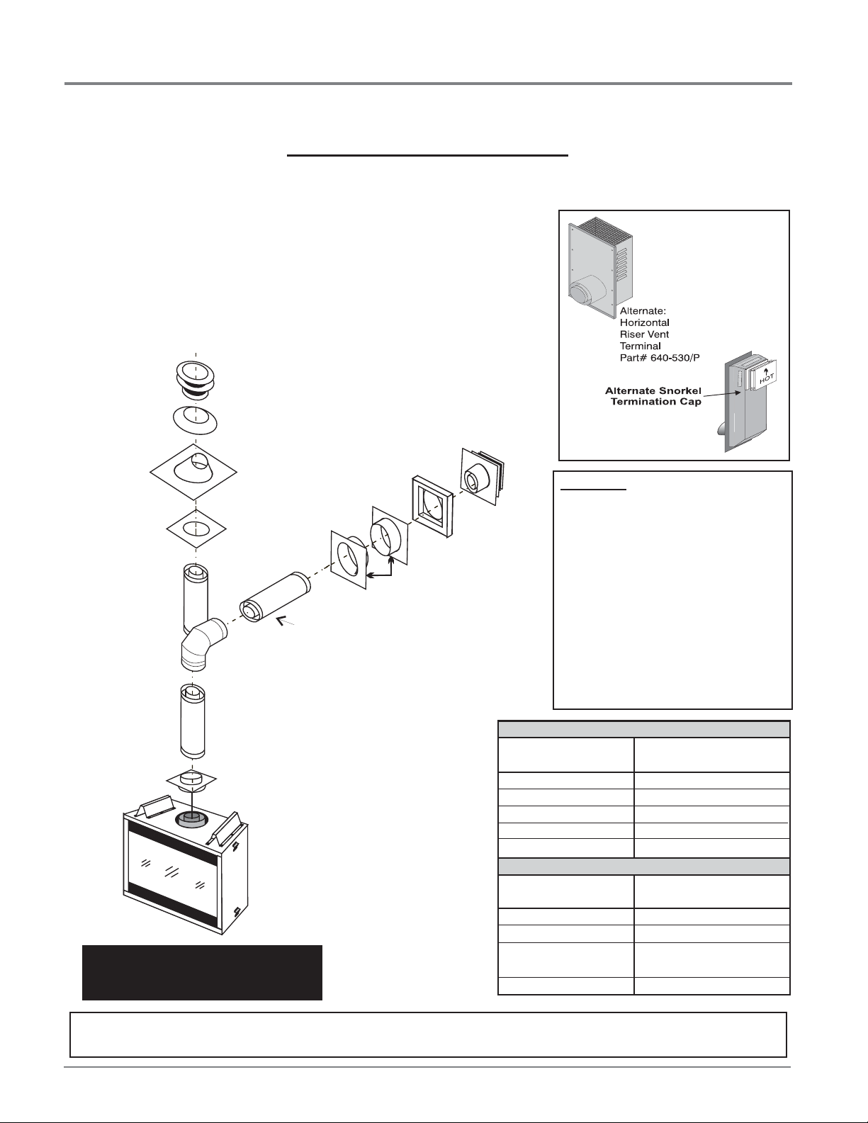
Rigid Pipe Adaptor
(Part# 510-994)
Pipe Length
Vertical
Terminal
Storm Collar
Part # 953
Flashing
943 or 943S
Ceiling Firestop
(Part # 963)
24" Pipe
Length
Adj.Pipe Length
11" - 14-5/8"
90 Elbow
o
Horizontal
Termination
Cap
Wall Thimble
Part # 942
Vinyl Siding
Standoff (Optional)
Part #950
INSTALLATION
RIGID PIPE VENTING
Horizontal or Vertical Terminations
The Rigid Pipe Venting System offers a complete line of component parts for installation of both horizontal and vertical installations. Many items are
offered in decorative black, as well as galvanized fi nish. We recommend using the galvanized fi nish for installation with the P42.
The minimum components required for a basic
horizontal termination are:
1 Horizontal Termination Cap
1 90
1 Flue Adaptor
1 Wall Thimble
1 Length of pipe to suit wall thickness
(see chart)
o
Elbow
When using Rigid Vent other than
Simpson Dura-Vent, 3 screws must be
used to secure rigid pipe to adaptor.
Wall thickness is measured from the back
standoffs to the inside mounting surface of
termination cap. For siding other than vinyl
furring strips may be used, instead of the vinyl
siding standoff, to create a level surface to
mount the vent terminal. The Terminal must
not be recessed into siding. Measure the wall
thickness including furring strips.
If a Vinyl Siding Standoff is required (it must
be used with vinyl siding), measure to outside
surface of wall without siding and add 2
inches.
Wall Thickness Vent Length
(inches) Required (inches)
4" - 5-1/2" 6"
7" - 8-1/2" 9"
10" - 11-1/2" 12"
9" - 14-1/2" 11" - 14-5/8" Adj. Pipe
15" - 23-1/2" 17" - 24" Adj. Pipe
Wall Thickness Vent Length
(inches) Required (inches)
3-1/4" - 6-3/4" 11" - 14-5/8" Adj. Pipe
7-3/4" - 16-1/4" 17" - 24" Adj. Pipe
7-1/4" - 8-3/4" 6" + 12"
9" + 9"
4-1/4" - 5-3/4" 6" + 9"
Alternate
Horizontal
Termination Caps
WARNING:
Do not combine venting components from
different venting systems.
However use of the the AstroCapTM and FPI
Riser is acceptable with all systems.
This product has been evaluated by Intertek for
using a Rigid Pipe Adaptor in conjunction with
Duravent Direct-Vent GS, Selkirk Direct-T emp,
Ameri Vent Direct venting and Security Secure
Vent systems. Use of these systems with the
Rigid Pipe adaptor is deemed acceptable
and does not affect the Intertek WHI listing of
components.
Flat Wall Installation
Corner Installation
The FPI AstroCap
American Metal Products Ameri Vent Direct Vent, Security Secure Vent®, Selkirk Direct-Temp. AstroCapTM is a proprietary trademark of FPI Fireplace
Products International Ltd. Dura-Vent® and Direct Vent are registered and/or proprietary trademarks of Simpson Dura-Vent Co. Inc.
14
TM
and FPI Riser Vent terminal are certifi ed for installations using FPI venting systems as well as Simpson Dura-Vent® Direct Vent,
Regency® P42-4 Zero Clearance Direct Vent Gas Fireplace
 Loading...