

Page 1
Gas Fireplaces
P36 - P36D Gas Fireplace
P36 - P36D Zero Clearance Direct Vent Gas Fireplace
Model P36-NG4 P36-LP4 P36D-NG1 P36D-LP1
Fuel Type Natural Gas Propane Natural Gas Propane
Minimum Supply
Pressure
Manifold
Pressure - High
Manifold
Pressure - Low
Orifi ce Size #37 DMS #52 DMS #37 DMS #52 DMS
Minimum Input
Maximum Input
Vent Sizing
5” W.C.
(1.25 kPa)
3.8” W.C.
(0.95 kPa)
1.1” W.C.
(0.27 kPa)
15,500 BTU/h
(4.54 kW)
30,000 BTU/h
(8.79 kW)
4” Inner / 6 5/8”
Outer
12” W.C.
(3.00 kPa)
11” W.C.
(2.74 kPa)
2.9” W.C.
(0.72 kPa)
15,000 BTU/h
(3.96 kW)
30,000 BTU/h
(8.79 kW)
4” Inner / 6 5/8”
Outer
5” W.C.
(1.25 kPa)
3.8” W.C.
(0.95 kPa)
1.1” W.C.
(0.27 kPa)
15,500 BTU/h
(4.54 kW)
30,000 BTU/h
(8.79 kW)
4” Inner / 6 5/8”
Outer
12” W.C.
(3.00 kPa)
11” W.C.
(2.74 kPa)
2.9” W.C.
(0.72 kPa)
15,000 BTU/h
(3.96 kW)
30,000 BTU/h
(8.79 kW)
4” Inner / 6 5/8”
Outer
Approved Venting Systems
Flex Vent Systems: FPI AstroCap™ Flex Vent
Rigid Pipe Vent Systems: Simpson Dura-Vent® Direct Vent GS
American Metal Products Ameri Vent
Security Secure Vent®
Selkirk Direct-Temp.
B
Gas Fireplaces
A
D
C
A
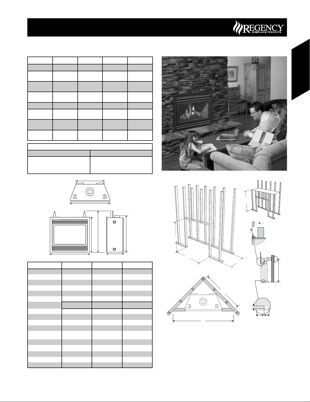
Unit Dimensions Description P36 P36D
A Front Face Width 36” (914mm) 36” (914mm)
B Rear Firebox Width 33-1/4” (838mm) 33-1/4” (838mm)
C Front Face Height 30-1/2” (775mm) 30-1/2” (775mm)
D Height w/ Standoff 36” (914mm) 37” (940mm)
E Unit Depth 12-3/4” (324mm) 17-1/8” (435mm)
F Height to Vent 32-1/2” (826mm) 32-1/2” (826mm)
Framing Dimensions Description P36 P36D
G Framing Width* 36-1/4” (921mm) 36-1/4” (921mm)
H*** Framing Height* *** 36-1/4” (921mm)*** 37-1/4” (946mm)***
I Framing Depth* 12-3/4” (324mm) 17-1/8” (435mm)
J Corner Wall Length 42-7/16” (1078mm) 48” (1219mm)
K
L Framed Chase Ceiling 46” (1168mm) 46-1/2” (1181mm)
M Vent Centerline Height 40-1/2” (1029mm) 40-1/2” (1029mm)
N Gas Connection Height 2” (51mm) 2” (51mm)
O Gas Connection Inset 3-1/2” (89mm) 3-1/2” (89mm)
P Gas Connection Width 4” (102mm) 4” (102mm)
Important: Framing height requires consideration of the hearth
***
depth. Dimension H = H + the thickness of installed hearth.
Corner Facing Wall
Width
60” (1524mm) 68” (1727mm)
F
E
L
Top Header
Drywall
(or other
H
facing)
10" (254mm)
dia. Hole through
wall Vent.
G
I
M
J
N
O
K
If using the Barcelona Surround, Kensington, Balmoral, or
*
Tripoli Screen Door please note that framing and facing must
P
Opening for gas
connection
be non combustible (12” on top and 6” on both sides) and that
the Barcelona is only approved for installation with a single
sidewall.
Please refer to Page 11 (Exterior Vent Terminations)
for additional guidelines on vent locations.
35June 2007 Regency Product Specifi cations Book
Page 2
P36 - P36D Gas Fireplace
Framing and Finishing
1) Determine the total thickness of facing material (e.g. drywall plus
ceramic tiles) to allow the fi nished surface to be fl ush with the front
of the unit. Total facing thickness can vary from 1/2” (13mm) to
1-1/4” (32mm) thick.
2) Frame in the enclosure for the unit with framing material.
Gas Fireplaces
Note: Header for the P36 must be installed vertically to maintain
clearances to combustible materials. Non combustible header may
be installed horizontally.
3) For exterior walls, insulate the enclosure to the same degree as
the rest of the house, apply vapor barrier and drywall, as per local
installation codes. (Do not insulate the fi replace itself.)
4) The top of the unit must not be closer than 32” (813mm) to the
ceiling.
5) Combustible material may be brought up to the top and sides of
the unit and be covered with ceramic tiles, bricks, rock or other
suitable combustible fi nishing materials.
If using the Barcelona Surround, Kensington, Balmoral, or
Tripoli Screen Door please note that framing and facing must
be non combustible (12” on top and 6” on both sides) and that
the Barcelona is only approved for installation with a single
sidewall.
Note: The unit does not have to be completely enclosed in a
chase. The clearance on top of the unit is 0” to the standoffs
so combustible building materials can be laid directly on top
of the standoffs. You must maintain proper clearances from
the vent to combustible materials (See Below).
6) Use metal studs for framing where the minimum clearance from
the vent to combustible material cannot be maintained.
Clearance Requirements
Gas Fireplaces
Vent Clearances Clearance Dimension
Horizontal - Top 2” (51mm)
Horizontal - Side 1-1/2” (38mm)
Horizontal - Bottom 1-1/2” (38mm)
Vertical (Flex or Rigid) 1-1/4” (32mm)
Failure to maintain required clearances is a major cause of
chimney related fi res. Installation of this fi replace must comply
with these clearances.
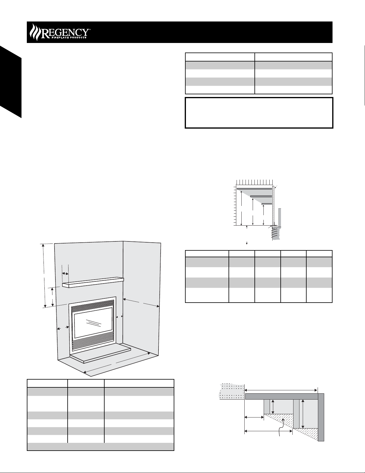
Combustible Mantels
Because of the extreme heat this fi replace emits, the mantel
clearances are critical. Combustible mantel clearances from top of
the louvers are shown in the diagram below. Mantel may be installed
anywhere in the shaded area or higher.
WARNING
Mantel Clearances
B
To base
of Unit
A
64810
12" (305mm)
7-1/2"(191mm)
3-1/2" (89mm)
C
Top of
Unit
12
0
0
2
Drywall
Standoff
D
Side View
C
D
A
F
B
B
E
Clearance: Dimension Measured From:
A: Mantel Height 7” (178mm) Minimum (Additional on this page)
B: Sidewall 6” (152mm) Side of installed front
Sidewall: Barcelona Only
C: Ceiling 32” (813mm) Top of installed unit
D: Mantel Depth 12” (305mm) Maximum (Additional on this page)
E: Alcove Width 48” (1219mm) Sidewall to Sidewall (Minimum)
F: Alcove Depth 36” (914mm) Front to back wall (Maximum)
Top of Hearth must not be higher than the base of the fi rebox.
8” (203mm)
Approved for single sidewall only
Mantel Clearances
with Flush Glass or
Hampton Cast
with Bay Option
with Flush Glass and
Barcelona Surround
with Tripoli Screen Door,
Kensington, or Balmoral
Front
ABCD
30-1/2”
(778mm)
30-1/2”
(778mm)
30-1/2”
(778mm)
30-1/2”
(778mm)
14” (356mm) 10” (254mm) 7” (178mm)
13” (330mm) 10” (254mm) 7” (178mm)
17” (432mm) 12” (305mm) 8” (203mm)
20” (508mm) N/A 12” (305mm)
Note: If desired a non-combustible mantel may be installed at a
lower height.
Note: Ensure the paint that is used on the mantel and the facing
is “heat resistant” or the paint may discolour.
Mantel Leg Clearances
Combustible mantel leg clearances as per diagram below:
Clearances are from the fi nished edge of the unit or an installed front.
P36 - P36D
8" Single Sidewall when using the Barcelona Surrround
Maximum
1-1/2” projection at 2”
minimum clearance.
6" Side Wall
Mantel leg
1-1/2"
2"
5"
Allowable mantel leg
projection.
Mantel leg
3"
36 June 2007 Regency Product Specifi cations Book
Page 3
Gas Fireplaces
FPI Direct Vent System (Flex)
Horizontal Terminations Only
These venting systems, in combination with the P36 / P36D Direct Vent
Gas Fireplace, have been tested and listed as a direct vent heater system
by Warnock Hersey. The location of the termination cap must conform
to the requirements in the Vent Terminal Locations diagram.
FPI Direct Vent (Flex) System Termination Kits include all the parts
needed to install the P36 / P36D using a fl exible vent.
FPI Kit # Length Contains:
#946-515 4 Feet 1) 6-5/8” fl exible liner (Kit length)
#946-516 10 Feet
Notes:
1) Liner sections should be continuous without any joints or seams.
2) Only Flex pipe purchased from Regency may be used for Flex
installations.
3) Horizontal sections must be supported every 3 feet.
Wall Thimble (2 pc)
4" (102mm)
dia. flue pipe
6-7/8"
(173mm) dia.
Flue pipe
2) 4” fl exible liner (Kit length)
3) spring spacers (3)
4) thimble (2)
5) AstroCap termination cap (1)
6) screws (12)
7) tube of Mill Pac (1)
8) plated screws (8)
9) S.S. screws #8 x 1-1/2” drill point, (4)
AstroCap
Termination Cap
Part #946-523/P
spring
spacer
Alternate Horizontal
Termination Caps
P36 - P36D Gas Fireplace
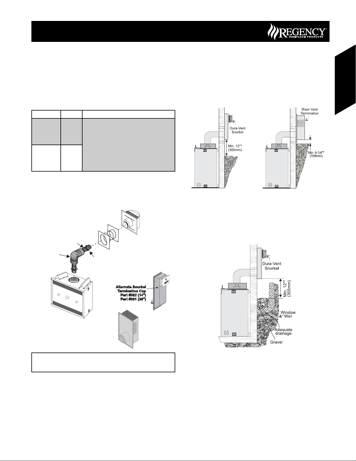
Snorkel Terminations
Gas Fireplaces
Snorkel Terminations:
For installations requiring a vertical rise on the exterior of the building,
14-inch and 36-inch tall Snorkel Terminations and the Riser Vent are
available. Follow the same installation procedures as used for standard
Horizontal Termination. NEVER install the snorkel upside down.
Below Grade Snorkel Installation (Dura-Vent Only)
If the Snorkel Termination must be installed below grade, i.e. basement
application, proper drainage must be provided to prevent water from
entering the Snorkel Termination. Refer to Rigid Pipe Installation
instructions for details. Do not attempt to enclose the Snorkel within the
wall, or any other type of enclosure.
Alternate:
Horizontal
Riser Vent
Terminal
Part# 640-530/P
If required by the external termination location the listed
alternate termination caps may be used. (Refer to Page 11)
37June 2007 Regency Product Specifi cations Book
Page 4
6
8
10
12
10
12
12 16
18
20 26
28
22 24
30
P36 - P36D Gas Fireplace
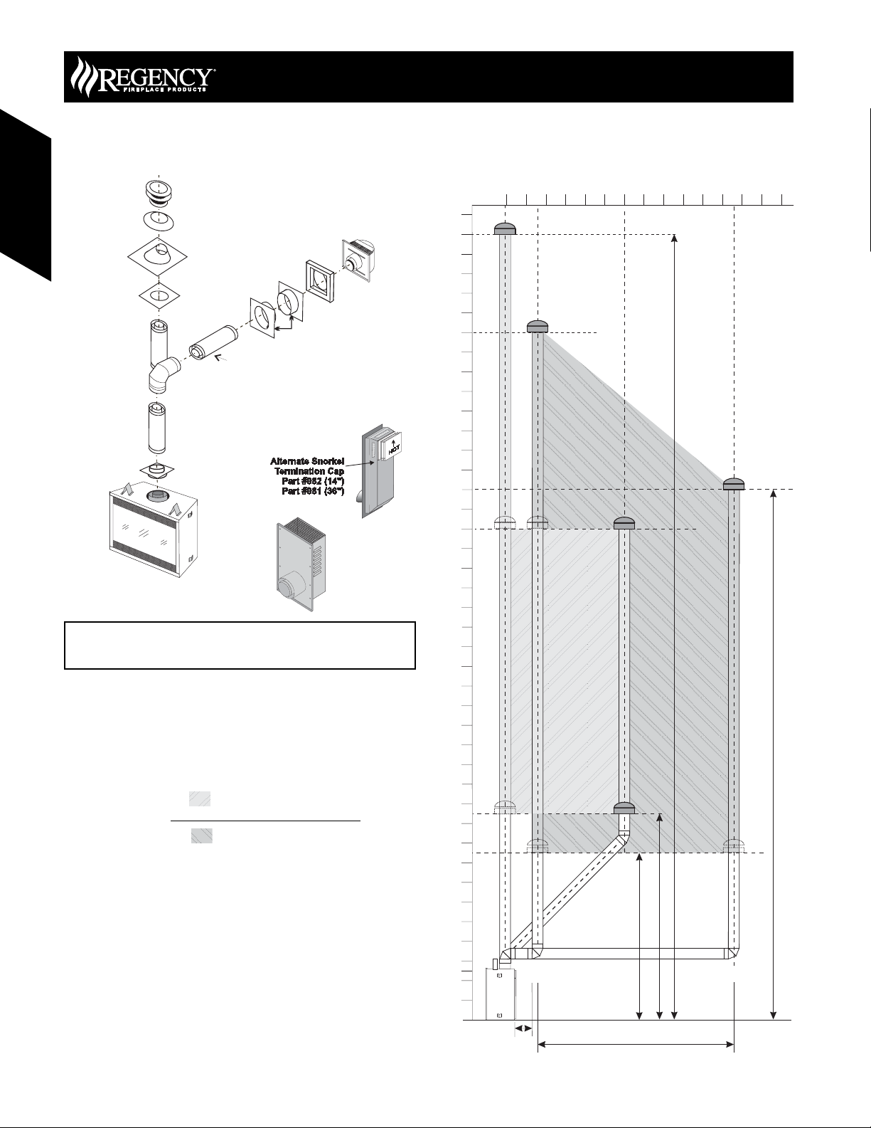
Rigid Pipe Venting
Horizontal or Vertical Terminations
Gas Fireplaces
Gas Fireplaces
Vertical
Terminal
Storm Collar
Part # 953
Flashing
943 or 943S
Ceiling Firestop
(Part # 963)
Pipe Length
Standoff (Optional)
Adj.Pipe Length
o
90 Elbow
11" - 14-5/8"
Pipe
Length
Rigid Pipe Adapter
(Part# 510-994)
Vinyl Siding
Part #950
Horizontal
Termination Cap
(Part #946-523/P)
Wall Thimble
Part # 942
Alternate Horizontal
Termination Caps
Alternate:
Horizontal
Riser Vent
Terminal
Part# 640-530/P
40
38
36
34
32
30
28
26
24
22
0
2
4
8
6
10 12
Maximum: 40 ft. (12.2m)
14
If required by the external termination location the listed
alternate termination caps may be used. (Refer to Page 11)
Venting Arrangements - Vertical
Terminations
Rigid Pipe System
(Propane & Natural Gas)
The P36 / P36D is approved for a maximum 40 ft. straight vertical, with
Rigid Pipe vent systems for Propane and Natural Gas.
The lightly shaded area,
confi gurations with a maximum of two 45° elbows allowed.
The darker shaded area,
confi gurations using two 90° elbows.
• Vent must be supported at offsets.
• Horizontal sections must be supported every 3 feet
• Firestops are required at each floor level and whenever
passing through a wall.
• Maintain clearances to combustible materials.
• Minimum of 1’ pipe section between elbows.
Note: Must use optional fl ue adapter when using Rigid Pipe (Part
# 510-994).
, in the diagram shows allowable venting
, in the diagram shows allowable venting
20
18
Vertical Height (Feet)
16
14
12
10
8
6
4
2
0
Minimum 12” (305mm)
Minimum 8’6” (2.6m)
Minimum 10’6” (3.2m)
Max. 10’ (3m)(centerline to centerline)
Maximum: 27 ft. (8.2m)
38 June 2007 Regency Product Specifi cations Book
Page 5
Gas Fireplaces
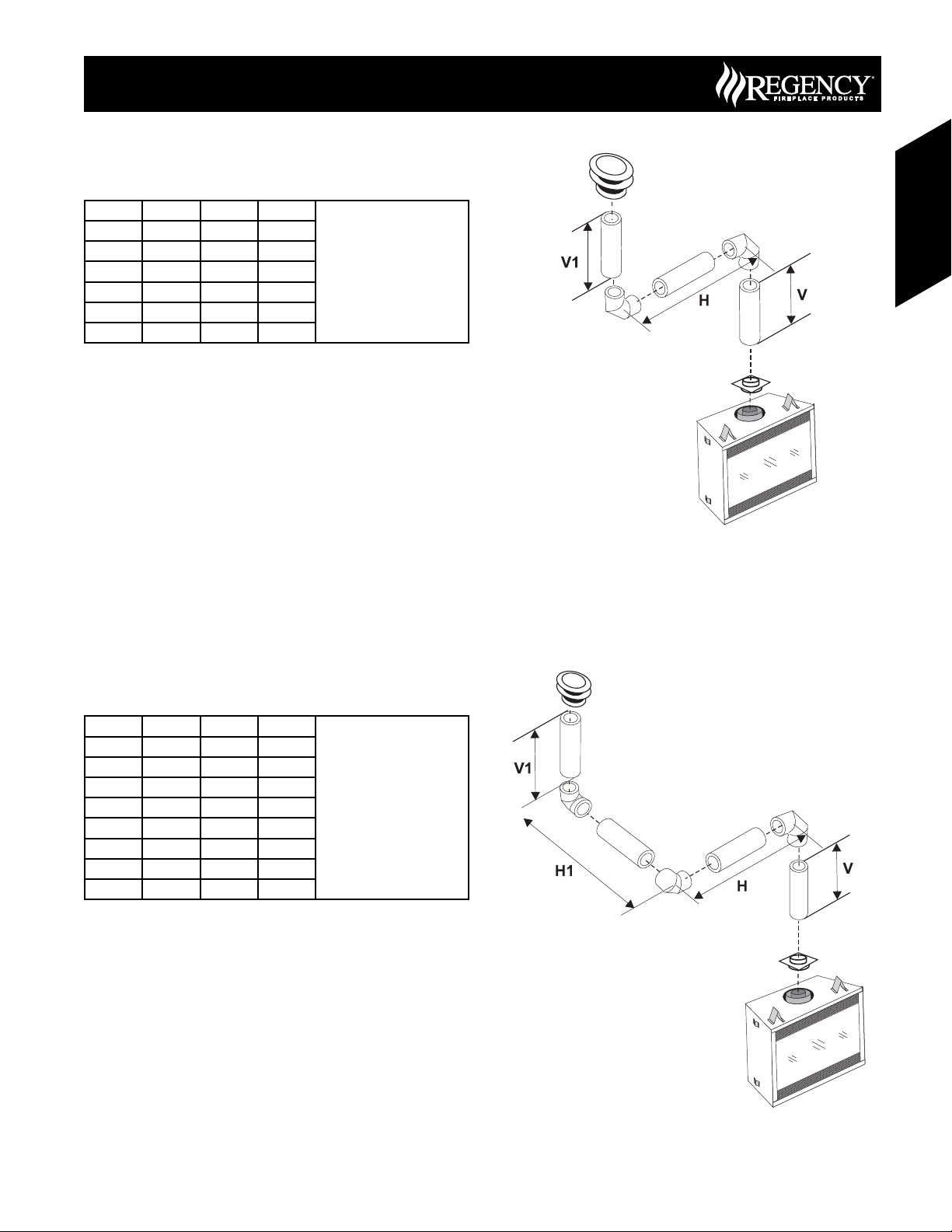
Vertical Venting
with Two (2) 90° Elbows
Two 45° elbows = One 90° elbow
P36 - P36D Gas Fireplace
Gas Fireplaces
Option V H V+ V1 Maximum total pipe: length, of
A) 0’ Min. 2’ Max. 1’ Min.
B) 1’ Min. 4’ Max. 3’ Min.
C) 2’ Min. 5’ Max. 4’ Min.
D) 3’ Min. 6’ Max. 5’ Min.
E) 4’ Min. 7’ Max. 6’ Min.
F) 5’ Min. 8’ Max. 7’ Min.
all sections, must not exceed
30 feet.
Total horizontal sections must
not exceed 8 feet.
Minimum of 1 foot between
90° elbows is required.
Vertical Venting
with Three (3) 90° Elbows
Two 45° elbows = One 90° elbow
Option V H + H1 V+ V1 Maximum total pipe: length, of
A) 0’ Min. 2’ Max. 2’ Min.
B) 1’ Min. 2’ Max. 3’ Min.
C) 2’ Min. 3’ Max. 4’ Min.
D) 3’ Min. 4’ Max. 6’ Min.
E) 4’ Min. 5’ Max. 7’ Min.
F) 5’ Min. 6’ Max. 8’ Min.
G) 6’ Min. 7’ Max. 9’ Min.
H) 7’ Min. 8’ Max. 10’ Min.
all sections, must not exceed
30 feet.
Total horizontal sections must
not exceed 8 feet.
Minimum of 1 foot between
90° elbows is required.
39June 2007 Regency Product Specifi cations Book
Page 6

P36 - P36D Gas Fireplace
6
8
10
12
10
12
Venting Arrangements - Horizontal
Terminations
This diagram shows all allowable combinations of vertical runs with
horizontal terminations, using one 90º elbow (two 45º
one 90º elbow).
Gas Fireplaces
The lightly shaded area,
combinations when installing a P36
The darker shaded area,
combinations when installing a P36D.
18
16
14
, in the diagram shows allowable
, in the diagram shows additional allowable
0
2
elbows equal
4
Gas Fireplaces
Note: Must use optional fl ue adapter (Part # 510-994) when using
• Maintain clearances to combustibles.
• Horizontal vent must be supported every 3 feet.
• Firestops are required at each fl oor level and whenever passing
A vent guard may be required as per local codes, refer to page 11 for
“Exterior Vent Termination Locations”.
Note: FPI Direct Vent System (Flex) is only approved for horizontal
Horizontal (Feet)
6
8
Rigid Pipe.
through a wall.
terminations.
10 14 16
12
18 20
12
10
P36D ONLY
8
Vertical Height (Feet)
6
4
40-1/2"
2
(1029mm)
Minimum
Height
Requirement
0
Please refer to Page 11 (Exterior Vent Terminations)
for additional guidelines on vent locations.
40 June 2007 Regency Product Specifi cations Book
Page 7
Gas Fireplaces
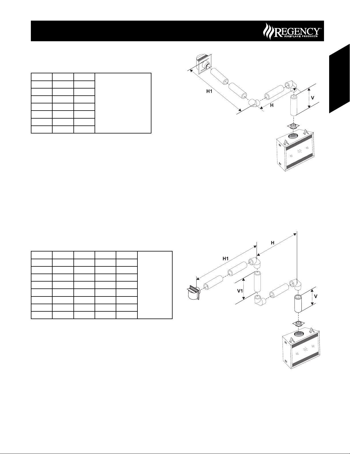
Horizontal Venting
with Two (2) 90° Elbows
Two 45° elbows = One 90° elbow
P36 - P36D Gas Fireplace
Gas Fireplaces
Option V H+ H1 Maximum total pipe: length, of
A) 0’ Min. 2’ Max.
B) 1’ Min. 3’ Max.
C) 2’ Min. 4’ Max.
D) 3’ Min. 5’ Max.
E) 4’ Min. 6’ Max.
F) 5’ Min. 7’ Max.
F) 6’ Min. 8’ Max.
all sections, must not exceed
30 feet.
Total horizontal sections must
not exceed 8 feet.
Minimum of 1 foot between
90° elbows is required.
Horizontal Venting
with Three (3) 90° Elbows
Two 45° elbows = One 90° elbow
Option V H V+ V1 H + H1 Maximum total
A) 0’ Min. 1’ Max. 1’ Min. 2’ Max.
B) 1’ Min. 2’ Max. 3’ Min. 3’ Max.
C) 2’ Min. 2’ Max. 5’ Min. 4’ Max.
D) 3’ Min. 2’ Max. 7’ Min. 5’ Max.
E) 4’ Min. 3’ Max. 9’ Min. 6’ Max.
F) 5’ Min. 4’ Max. 10’ Min. 7’ Max.
G) 6’ Min. 5’ Max. 11’ Min. 8’ Max.
H) 7’ Min. 6’ Max. 12’ Min. 9’ Max.
pipe: length, of
all sections, must
not exceed 30
feet.
Total horizontal
sections must not
exceed 8 feet.
Minimum of 1
foot between
90° elbows is
required.
41June 2007 Regency Product Specifi cations Book
Page 8

P36 - P36D Gas Fireplace
Vertical termination with co-linear
fl ex system
The appliance must not be connected to a chimney fl ue
serving a separate solid fuel burning appliance.
Gas Fireplaces
Masonry chimneys may take various contours which the fl exible liner
will accommodate. However, keep the fl exible liner as straight as
possible, avoid unnecessary bending.
The Air Intake pipe must be attached to the inlet air collar of the
termination cap.
This appliance is designed to be attached to two 3” (76mm) co-linear
aluminium fl ex running the full length of the chimney. See the Venting
Arrangements for minimum and maximum heights.
Gas Fireplaces
Required Parts:
Part # Description
946-529 Co-linear DV Vertical Termination Cap
948-305 3” Flex - 35 ft.
946-563 Coaxial to Co-linear Adapter Kit which contains
510-994 Flue Adapter
945 45º Elbow
Alternate Approved Caps
980 Vertical Termination Cap
991 High Wind Cap
923GK
the following: Co-linear Flex Adapter Outer Pipe
Inner Pipe Adapter
3” Co-linear Adapter with fl ashing
Pipe Length
Rigid Pipe Adapter
# 510-994
Vertical Termination
A maximum
of two certified
joiner kits
may be used
per length.
#948-305 (35 ft)
Exhaust
Outer
Pipe
with Kit#
946-563
90 Degree
Co-linear DV
Cap # 946-529
Flue
Elbow
Inner Pipe
Adapter
with Kit#
946-563
Flex Liner
Air Intake
Co-Linear
Flex
Adapter
with Kit#
946-563
30
30' Max.
Vertical Height (feet)
8' Min.
2’ max.
40-1/2”
Horizontal Distance (Feet)
The shaded area in the diagrams
show the allowable vertical
terminations.
Please refer to Page 11
(Exterior Vent Terminations)
for additional guidelines on
vent locations.
42 June 2007 Regency Product Specifi cations Book
 Loading...