

Regency P36D Installation Manual
P36D Zero Clearance
WARNING:
If the information in these instructions are not followed exactly, a fire or
explosion may result causing property damage, personal injury or loss of
life.
FOR YOUR SAFETY
Do not store or use gasoline or other flammable vapors and liquids in the
vicinity of this or any other appliance.
Installation and service must be performed by a qualified installer, service
agency or the gas supplier.
FOR YOUR SAFETY
What to do if you smell gas:
Do not try to light any appliance
Do not touch any electrical switch: do not
use any phone in your building.
Immediately call your gas supplier from a
neighbour's phone. Follow the gas
supplier's instructions.
If you cannot reach your gas supplier, call
the fire department.
Direct Vent Gas Fireplace
MODELS: P36D-NG Natural Gas P36D-LP Propane
Owners & Installation Manual
Tested by:
918-059g
FPI FIREPLACE PRODUCTS INTERNATIONAL LTD. 6988 Venture St., Delta, BC Canada, V4G 1H4
Installer: Please complete the details on the back cover
and leave this manual with the homeowner.
Homeowner: Please keep these instructions for future reference.
06/15/05
To the New Owner:
Congratulations!
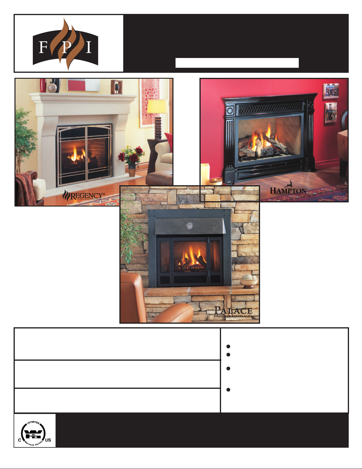
You are the owner of a state-of-the-art Gas Fireplace by FPI FIREPLACE PRODUCTS
INTERNATIONAL L TD. The P36D is a hand crafted appliance and has been designed to provide
you with all the warmth and charm of a wood fireplace at the flick of a switch. The model P36D
has been approved by Warnock Hersey for both safety and efficiency. As it also bears our own
mark, it promises to provide you with economy, comfort and security for many trouble free years
to follow. Please take a moment now to acquaint yourself with these instructions and the many
features of your FPI Fireplace.
INFORMATION FOR MOBILE/MANUFACTURED HOMES AFTER FIRST SALE
This FPI product has been tested and listed by Warnock Hersey to the following standards: VENTED GAS FIREPLACE HEATERS ANSI Z21.88b2003/CSA 2.33b-2003 and GAS-FIRED APPLIANCES FOR USE AT HIGH ATLITUDES CAN/CGA 2.17-M91.
This Direct Vent System Appliance must be installed in accordance with the manufacturer's installation instructions and the Manufactured Home
Construction and Safety Standard, Title 24 CFR, Part 3280, or the current Standard of Fire Safety Criteria for Manufactured Home Installations, Sites,
and Communities ANSI/NFPA 501A, and with CAN/CSA Z240-MH Mobile Home Standard in Canada.
This appliance installation must comply with the manufacturer's installation instructions and local codes, if any. In the absence of local codes follow
the current National Fuel Gas Code, ANSI Z223.1 and the current National Electrical Code ANSI/NFPA 70 in the U.S.A., and the current CAN/CGA
B149 Gas Installation Code and the current Canadian Electrical Code CSA C22.1 in Canada.
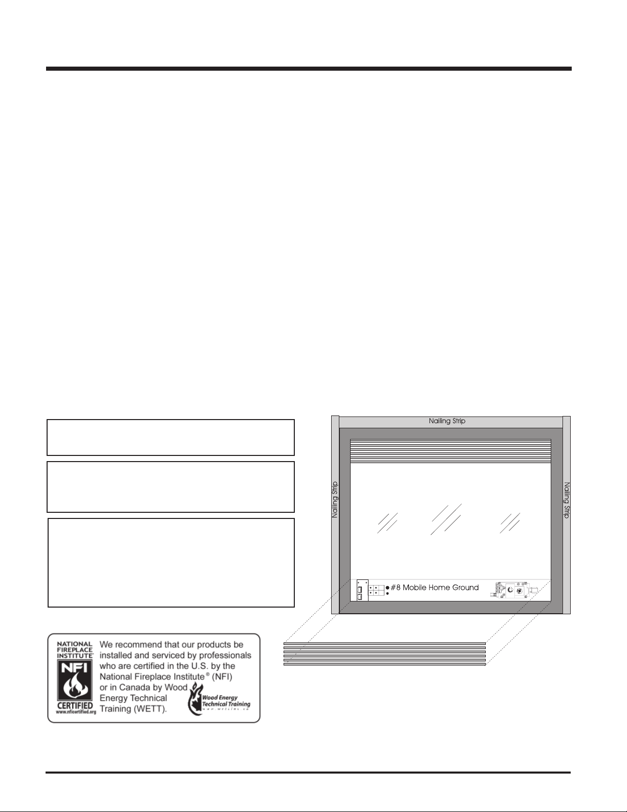
This FPI Mobile/Manufactured Home Listed appliance
comes factory equipped with a means to secure the unit.
This FPI Mobile/Manufactured Home listed appliance comes
equipped with a dedicated #8 ground lug to which an 18
gauge copper wire from the steel chassis ground must be
attached.
This appliance may only be installed in an aftermarket
permanently located, manufactured (mobile) home, where
not prohibited by local codes.
This appliance is only use with the type of gas indicated
on the rating plate. This appliance is not convertible for
use with other gases, unless a certified kit is used.
2
FPI P36D Zero Clearance Direct Vent Gas Fireplace

TABLE OF CONTENTS
SAFETY LABEL
Safety Label .........................................................................5
INSTALLATION
Unit Dimensions .................................................................6
Before You Start...................................................................7
General Safety Information ..................................................7
Installation Checklist ...........................................................7
Locating Your Gas Fireplace ...............................................8
Manufactured Home Additional Requirements .................. 8
HeatWave Duct System (optional) ......................................8
Heat Release Kit (optional) ................................................. 8
Clearances..........................................................................9
Regency Clearances ................................................ 10
Arch Door Clearances ............................................... 10
Hampton Clearances ............................................... 10
Palace Series Clearances........................................ 10
Regency Mantel Clearances ............................................ 11
Hampton Mantel Clearances ........................................... 13
Palace Series Mantel Clearances ................................... 14
Mantel Leg Clearances .................................................... 1 5
Horizontal Venting with Two Elbows ................................ 27
Vertical Venting with Two Elbows .................................... 28
Vertical Terminations - Co-Linear Flex System ............... 2 9
Venting Arrangements - Vertical Terminations ................ 3 0
Venting - Dura-Vent Horizontal Installations .................... 31
Venting - Dura-Vent Vertical Termination......................... 32
Venting - Installation for Direct Vent System (Flex) .......... 3 3
System Data ..................................................................... 3 4
High Elevation .................................................................. 34
Gas Line Installation ........................................................ 34
Pilot Adjustment ............................................................... 34
Gas Pipe Pressure Test .................................................. 3 4
SIT Valve Description ....................................................... 34
Conversion to Propane .................................................... 35
Brick Panels (optional) ..................................................... 3 6
Log Set Installation ........................................................... 36
Flush Door ........................................................................ 38
Remote Wall Switch (optional) ......................................... 39
Remote Control (optional) ............................................... 39
Wall Thermostat (optional) ............................................... 39
Wiring Diagram ................................................................ 40
Fan Installation (optional) ................................................ 41
Framing and Finishing ..................................................... 16
Barcelona & Palace Series Framing Note ....................... 1 7
Arch Door Framing Note .................................................. 1 8
Unit Assembly Prior to Installation
Top Standoff Assembly ............................................. 1 9
Top Facing Suprt & Side Nailing Strip Assembly ..... 19
Venting Introduction .......................................................... 1 9
Exterior Vent Termination Locations ................................ 20
Venting ............................................................................ 21
Direct Vent System (Flex) .......................................... 21
Rigid Pipe Venting Components list ........................ 22
Rigid Pipe Venting Systems ..................................... 23
Venting Arrangements
Horizontal Terminations............................................ 24
Vertical Terminations ................................................ 25
OPERATING INSTRUCTIONS
Operating Instructions...................................................... 42
Lighting Procedure ........................................................... 42
Shutdown Procedure........................................................ 42
First Fire............................................................................ 42
Aeration Adjustment ......................................................... 4 2
Normal Operating Sounds ............................................... 42
Lighting Plate Instructions ............................................... 43
NOTE: All installation instructions apply to
Regency, Hampton & The Palace Series unless otherwise specified.
FPI P36D Zero Clearance Direct Vent Gas Fireplace 3

TABLE OF CONTENTS
MAINTENANCE
Maintenance Instructions ................................................. 43
General Vent Maintenance ............................................... 44
Gold-Plated or Brass Louvers ......................................... 4 4
Gold Plated or Brass Trim ............................................... 4 4
Log Replacement............................................................. 44
Thermopile/Thermocouple .............................................. 44
Glass Gasket.................................................................... 44
Door Glass ....................................................................... 44
Flush Glass Replacement........................................ 44
Bay Glass Replacement ........................................... 4 4
Removing Valve................................................................ 45
Installing Valve ................................................................. 4 5
REGENCY
FLUSH & BAY DOOR OPTIONS
Flush Trim ........................................................................ 47
Louvers - Flush ................................................................. 4 7
Double Screen Door ........................................................ 4 7
HAMPTON
CAST FACEPLATE OPTION
Hampton Cast Faceplate ................................................. 5 4
Hampton Cast Grills ........................................................ 55
PALACE SERIES OPTIONS
The Kensington Front ....................................................... 5 7
The Westminster Front ..................................................... 58
The Balmoral Front ........................................................... 5 9
REPLACEMENT PARTS LIST
Part List ............................................................................ 6 2
WARRANTY
Warranty............................................................................ 71
Bay Front........................................................................... 48
Bay Trim............................................................................ 48
Louvers - Bay ................................................................... 48
Full Screen Front .............................................................. 49
Arch Screen Door ............................................................. 51
4
FPI P36D Zero Clearance Direct Vent Gas Fireplace
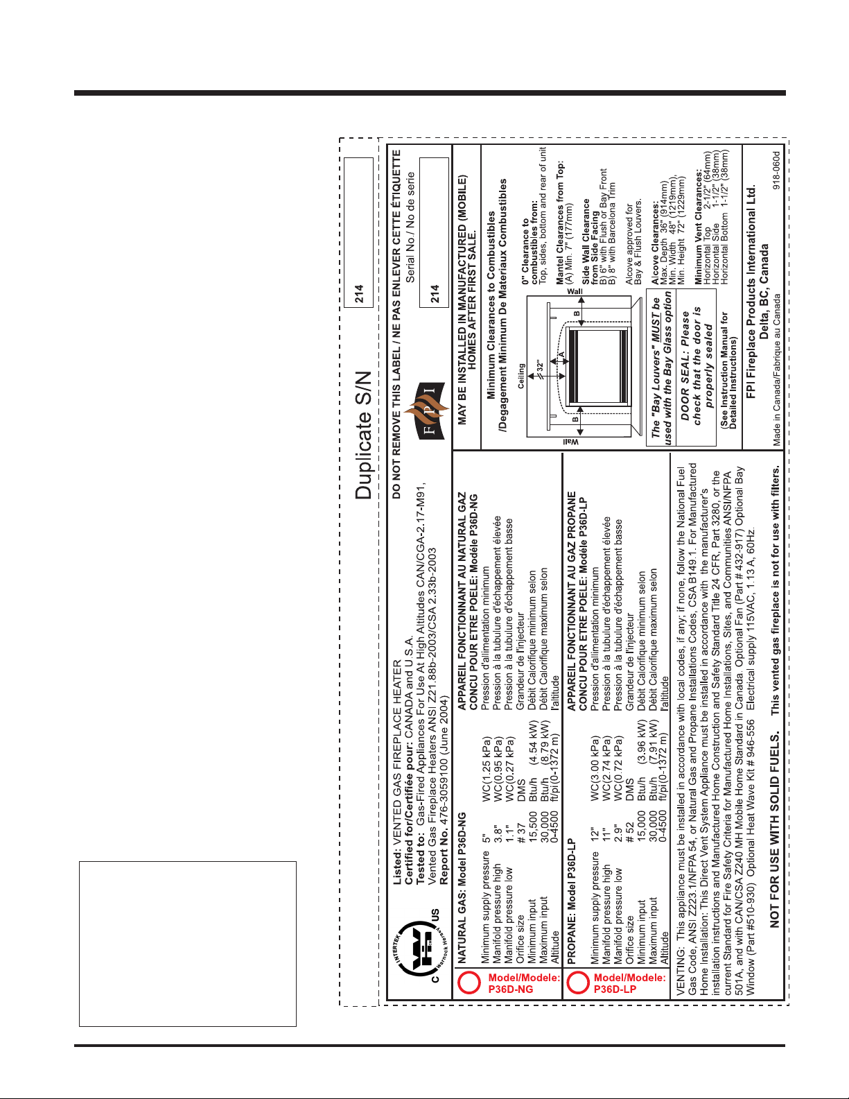
This is a copy of the label that accompanies
each P36D Zero Clearance Direct Vent Gas
Fireplace. We have printed a copy of the
contents here for your review. The safety label
is located on the front inside base of the unit,
visible when the bottom louver is open.
NOTE: FPI units are constantly being improved.
Check the label on the unit and if there is a
difference, the label on the unit is the correct
one.
SAFETY LABEL
For the State of Massachusetts, installation
and repair must be done by a plumber or
gasfitter licensed in the Commonwealth of
Massachusetts.
For the State of Massachusetts, flexible
connectors shall not exceed 36 inches in
length.
For the State of Massachusetts, the appliances individual manual shut-off must be a
t-handle type valve.
Copy of Safety Decal for P36D
FPI P36D Zero Clearance Direct Vent Gas Fireplace 5
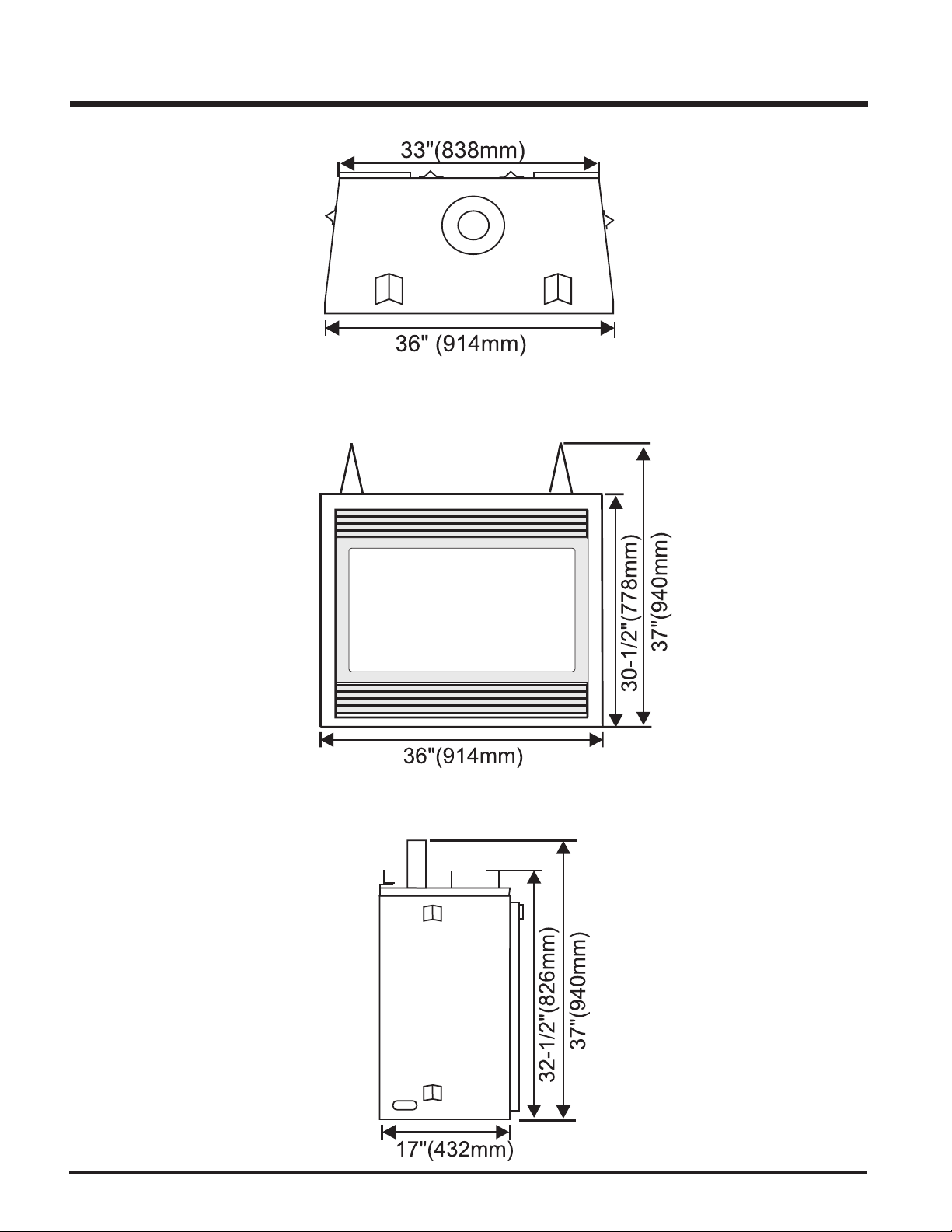
UNIT DIMENSIONS
6
FPI P36D Zero Clearance Direct Vent Gas Fireplace
INSTALLATION
IMPORTANT:
SAVE THESE
INSTRUCTIONS
The P36D-NG or P36D-LP Direct Vent Fireplace
must be installed in accordance with these instructions. Carefully read all the instructions in this
manual first. Consult the "authority having jurisdiction" to determine the need for a permit prior to
starting the installation. It is the responsibility of the
installer to ensure this fireplace is installed in
compliance with manufacturer's instructions and
all applicable codes.
BEFORE YOU START
Safe installation and operation of this appliance
requires common sense, however, we are
required by the Canadian Safety Standards
and ANSI Standards to make you aware of the
following:
INSTALLATION AND REPAIR SHOULD
BE DONE BY A QUALIFIED SERVICE
PERSON. THE APPLIANCE SHOULD BE
INSPECTED BEFORE USE AND AT
LEAST ANNUALLY BY A PROFESSIONAL SERVICE PERSON. MORE FREQUENT
CLEANING MAY BE REQUIRED DUE TO
EXCESSIVE LINT FROM CARPETING,
BEDDING MATERIAL, ETC. IT IS IMPERATIVE THAT CONTROL COMPARTMENTS, BURNERS AND CIRCULATING
AIR PASSAGEWAYS OF THE APPLIANCE BE KEPT CLEAN.
DUE TO HIGH TEMPERATURES, THE
APPLIANCE SHOULD BE LOCATED OUT
OF TRAFFIC AND AWAY FROM FURNITURE AND DRAPERIES.
WARNING: FAILURE TO INSTALL THIS
APPLIANCE CORRECTLY WILL VOID
YOUR WARRANTY AND MAY CAUSE A
SERIOUS HOUSE FIRE.
CHILDREN AND ADULTS SHOULD BE
ALERTED TO THE HAZARDS OF HIGH
SURFACE TEMPERATURES, ESPECIALLY THE FIREPLACE GLASS, AND
SHOULD STAY AWAY TO AVOID BURNS
OR CLOTHING IGNITION.
YOUNG CHILDREN SHOULD BE CAREFULLY SUPERVISED WHEN THEY ARE
IN THE SAME ROOM AS THE APPLIANCE.
CLOTHING OR OTHER FLAMMABLE MATERIAL SHOULD NOT BE PLACED ON
OR NEAR THE APPLI
ANCE.
GENERAL SAFETY
INFORMATION
1) The appliance installation must conform
with local codes or, in the absence of local
codes, with the current Canadian or National Gas Codes, CAN1-B149 or ANSI
Z223.1 Installation Codes.
2) The appliance when installed, must be
electrically grounded in accordance with
local codes, or in the absence of local
codes with the current National Electrical
Code, ANSI/NFPA 70 or CSA C22.1 Canadian Electrical Code.
3) See general construction and assembly
instructions. The appliance and vent should
be enclosed.
4) This appliance must be connected to the
specified vent and termination cap to the
outside of the building envelope. Never
vent to another room or inside a building.
Make sure that the vent is fitted as per
Venting instructions.
5) Inspect the venting system annually for
blockage and any signs of deterioration.
6) Venting terminals shall not be recessed into
a wall or siding.
7) Any safety glass removed for servicing
must be replaced prior to operating the
appliance.
8) To prevent injury, do not allow anyone who
is unfamiliar with the operation to use the
fireplace.
9) Wear gloves and safety glasses for protection while doing required maintenance.
10)Be aware of electrical wiring locations in
walls and ceilings when cutting holes for
termination.
11)Under no circumstances should this appliance be modified. Parts that have to be
removed for servicing should be replaced
prior to operating this appliance.
12)Installation and any repairs to this appliance
should be done by a qualified service person. A professional service person should
be called to inspect this appliance annually.
Make it a practice to have all of your gas
appliances checked annually.
14)Under no circumstances should any solid
fuels (wood, paper, cardboard, coal, etc.)
be used in this appliance.
15)The appliance area must be kept clear and
free of combustible materials, (gases and
other flammable vapours and liquids).
Emissions from burning wood or gas could
contain chemicals known to the State of
California to cause cancer, birth defects or
other reproductive harm.
INSTALLATION
CHECKLIST
1) Locate appliance
a) Room location, page 8.
b) Clearances to Combustibles, pages 9 -
14.
c ) Mantle Clearances, pages 11 - 13.
d) Framing & Finishing Requirements,
page 15.
e) Venting Requirements, pages 21 - 25.
2) Assemble Top Standoffs and Top Facing
Support and Side Nailing Strips, page 19.
(NOTE: must be done before installing unit
into fireplace.)
3) Install vent, pages 30 - 32.
4) Make gas and electrical connections. Test
the pilot. Must be as per diagram. Page 34.
5) Install brick panels (optional), page 36.
6) Install log set where indicated on page 36.
7) Install standard Flush Door, page 35.
8) Install Optional Regency Flush or Bay Fronts.
pages 47 - 51.
9) Install Optional Hampton Cast Faceplate,
page 54.
10)Install Optional Palace Series Fronts, pages
57 - 59.
11)Install optional Wall Switch, Remote Control, or Wall Thermostat, page 39.
12)Install Optional Fan, page 41.
13)Final check.
13)Do not slam shut or strike the glass door.
FPI P36D Zero Clearance Direct Vent Gas Fireplace 7
INSTALLATION
This includes:
1) Clocking the appliance to ensure the cor-
rect firing rate (rate noted on label 30,000
Btu/h) after burning appliance for 15 minutes.
2) If required, adjusting the primary air to
ensure that the flame does not carbon. First
allow the unit to burn for 15-20 min. to
stabilize.
CAUTION: Any alteration to the product
that causes sooting or carboning that
results in damage is not the responsibility of the manufacturer.
LOCATING YOUR
GAS FIREPLACE
1) When selecting a location for your fire-
place, ensure that the clearances outlined
on this page are met.
2) Provide adequate clearances for servicing.
3) The appliance must be installed on a flat,
solid, continuous surface (e.g. wood, metal, concrete). This may be the floor, or
raised up on a platform to enhance its visual
impact. If the appliance is going to be installed on carpeting, combustible linoleum
tile or other combustible material other than
wood flooring, the appliance must be installed on a metal or wood panel extending
the full width and depth of the appliance.
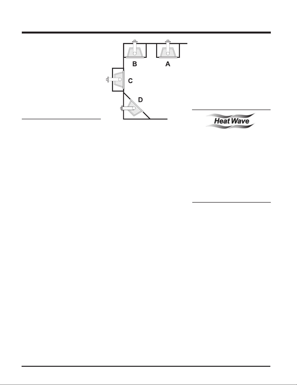
4) The P36D Direct Vent Gas Fireplace can be
installed in a recessed position or framed
out into the room as in A, B, C, D. See
Diagram 1.
Diagram 1
A) Flat on Wall
B) Flat on Wall Corner
C) Recessed into Wall/Alcove
D) Corner
5) This appliance is Listed for bedroom instal-
lations when used with a Listed Millivolt
Thermostat. Some areas may have further
requirements, check local codes before
installation.
6) The P36D Direct Vent Gas Fireplace is
approved for alcove installations, which
meet the clearances listed on this page.
7) We recommend that you plan your installation on paper using exact measurements
for clearances and floor protection before
actually installing this appliance. Have a
qualified inspector, dealer, or installer review your plans before installation.
Note: For vent terminations see page 20.
MANUFACTURED
MOBILE HOME
ADDITIONAL
REQUIREMENTS
1) Ensure that structural members are not cut
or weakened during installation.
2) Ensure proper grounding using the #8
ground lug provided. See page 40.
DUCT SYSTEM
OPTION KIT #946-556
The HeatWave Air Duct Kit increases the
effectiveness of your fireplace by dispersing
warm air from the fireplace to remote locations
in the same room or other rooms in your home.
Up to two kits may be installed on the fireplace.
Please Note: Only 1 HeatWave kit may be
operated at one time. This includes the internal
blower option as well.
OPTIONAL
HEAT RELEASE
KIT #946-570
The Heat Release Kit expels warm air from the
fireplace to the outside of the building, allowing
the fireplace to be operated with less heat
entering the room. The kit may be used on either
the left or right side.
8
FPI P36D Zero Clearance Direct Vent Gas Fireplace
INSTALLATION
CLEARANCES
The clearances listed below are Minimum distances unless otherwise stated:
A major cause of chimney related fires is failure to maintain required clearances (air space) to combustible materials. It is of
the greatest importance that this fireplace and vent system be installed only in accordance with these instructions.
IMPORTANT: See page 17 for framing note on Barcelona Trim and Palace Series Fronts.
Clearance to Combustibles from:
Back 0" (0mm)
Side 0" (0mm)
Floor 0" (0mm)
NOTE: The minimum floor clearance must be maintained from the top surface of the carpeting, tile, etc.
Minimum Clearance from Top of Unit to:
Ceiling from top of unit. 32" (1016mm)
Side Wall Clearances:
Bay or Flush Front 6"* (152mm)
Barcelona Trim 6"* (152mm)
Cast Faceplate 6"* (152mm)
Kensington Front 6"* (152mm)
Balmoral & Westminster Front 6"* (152mm)
* Measured from Surround or Front. See page 14 for dimensions.
Horizontal Vent Clearances:
Top 2" (51mm)
Side 1-1/2"(38mm)
Bottom 1-1/2"(38mm)
Vertical Vent Clearances 1-1/4" (32mm)
Alcove Clearances**:
Max. Depth 36" (914mm)
Min. Width 48" 1219mm)
Min. Height 72" 1829mm)
**Approved for one sidewall installation only when using Barcelona Trim.
WARNING: Fire hazard is an extreme risk if these clearances are not adhered to.
Heat Release Kit
The HeatWave Duct Kit and the Heat
Release Kit have different clearance
and framing requirements, check the
HeatWave and Heat Release manual
for details.
To install the combination of the Barcelona front and screen doors
you must use non-combustible mantel in conjunction with the
already required framing specs for the Barcelona front.
Steel studs and non-combustible material on the facing must be
adhered to.
Barcelona & Double Screen Door Installations
FPI P36D Zero Clearance Direct Vent Gas Fireplace 9
INSTALLATION
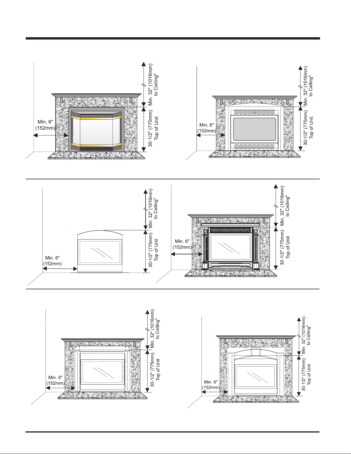
REGENCY CLEARANCES
Clearances for Bay or Flush Front
ARCH DOOR CLEARANCES
PALACE SERIES CLEARANCES
Clearances for Barcelona Trim
HAMPTON CLEARANCES
10
Clearances for The Balmoral &
The Westminster Front
Clearances for The Kensington Front
FPI P36D Zero Clearance Direct Vent Gas Fireplace
INSTALLATION
Diagram 3
framing is made of metal studs covered with a non-combustible board.
Note: A non-combustible mantel may be installed at a lower height if the
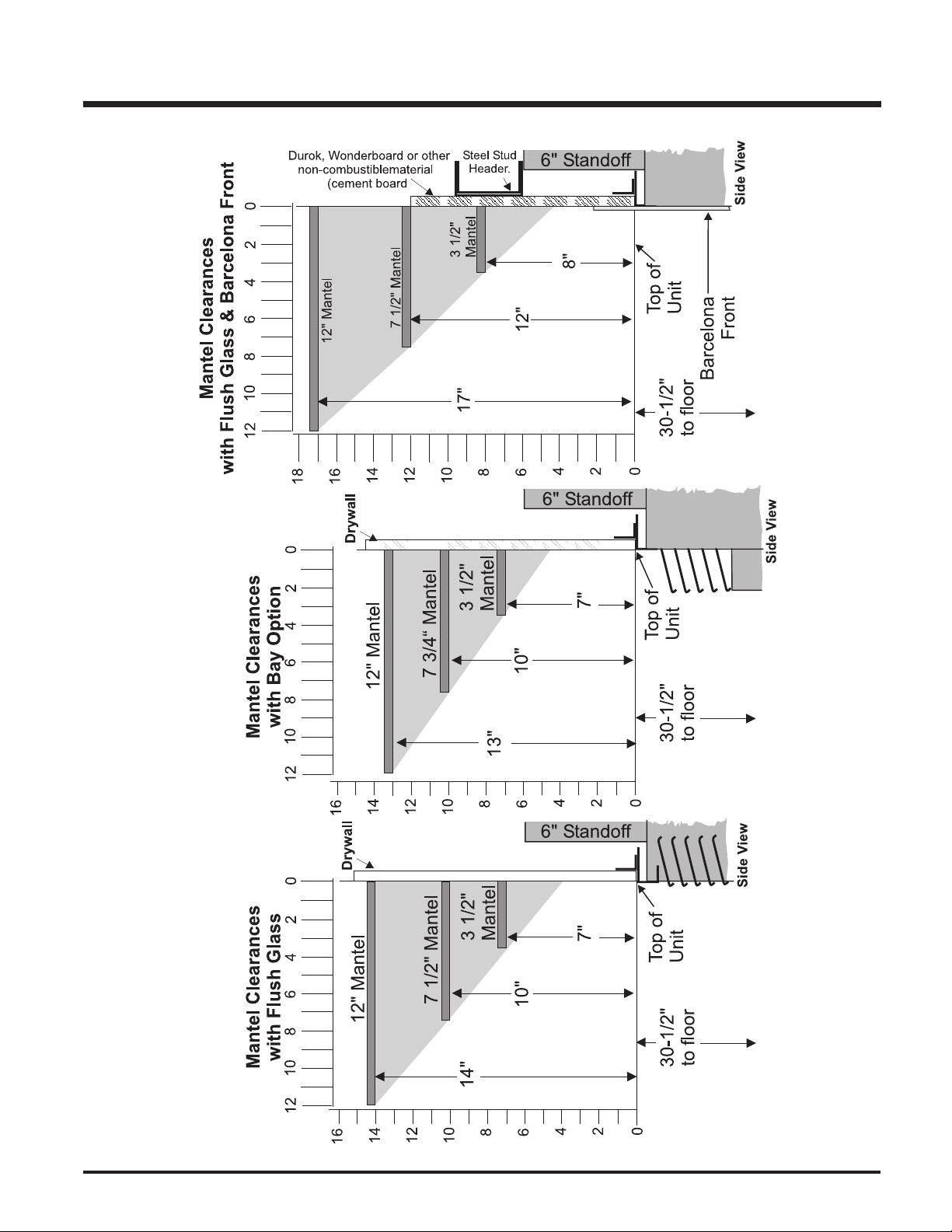
REGENCY COMBUSTIBLE MANTEL CLEARANCES
Diagram 2
Diagram 1
These drawings are to scale at 1:6 (one inch = 6 inches)
Mantel can be installed anywhere in shaded area or higher using the above scale.
Note: Ensure the paint that is used on the mantel and the facing is "heat resistant" or the paint may discolour.
Because of the extreme heat this fireplace emits, the mantel clearances are
critical.
Combustible mantel clearances from top of unit are shown in Diagrams 1, 2, & 3.
FPI P36D Zero Clearance Direct Vent Gas Fireplace 11
INSTALLATION
REGENCY SERIES COMBUSTIBLE MANTEL CLEARANCES
Because of the extreme heat this fireplace emits, the mantel clearances are critical.
Combustible mantel clearances from top of unit are shown in the diagram below.
Note: A non-combustible mantel may be installed at a lower height if the framing is made of metal studs covered with a non-
combustible board.
These drawings are to scale at 1:6 (one inch = 6 inches)
Mantel can be installed anywhere in shaded area or higher using the above scale.
Note: Ensure the paint that is used on the mantel and the facing is "heat resistant" or the paint may discolour.
12
FPI P36D Zero Clearance Direct Vent Gas Fireplace
INSTALLATION
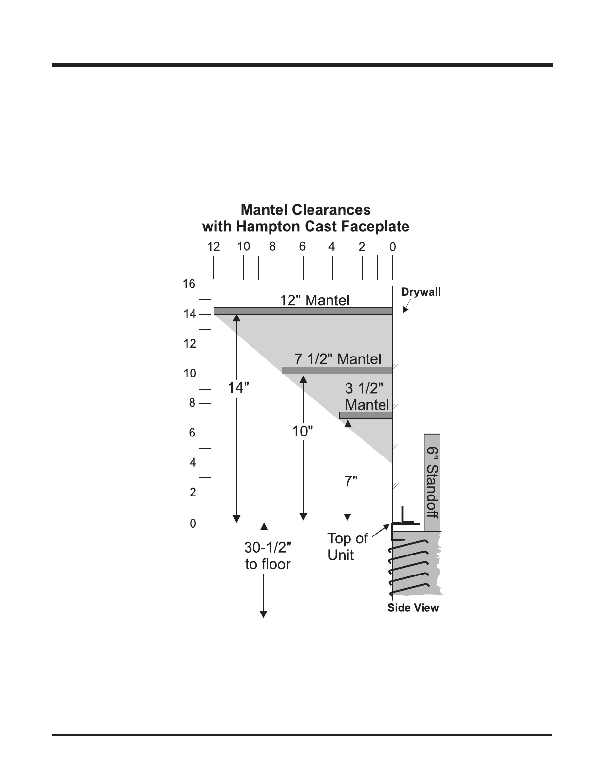
HAMPTON COMBUSTIBLE MANTEL CLEARANCES
Because of the extreme heat this fireplace emits, the mantel clearances are critical.
Combustible mantel clearances from top of unit are shown in the diagram below.
Note: A non-combustible mantel may be installed at a lower height if the framing is made of metal studs covered with a non-
combustible board.
These drawings are to scale at 1:6 (one inch = 6 inches)
Mantel can be installed anywhere in shaded area or higher using the above scale.
Note: Ensure the paint that is used on the mantel and the facing is "heat resistant" or the paint may discolour.
FPI P36D Zero Clearance Direct Vent Gas Fireplace 13
INSTALLATION
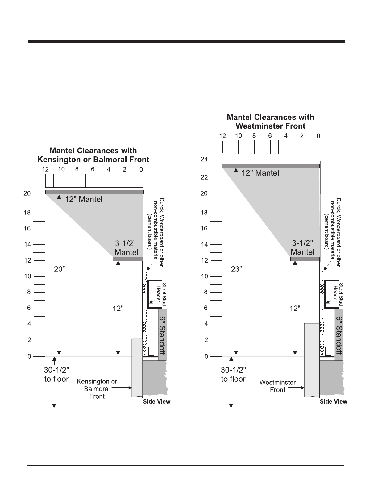
PALACE SERIES COMBUSTIBLE MANTEL CLEARANCES
Because of the extreme heat this fireplace emits, the mantel clearances are critical.
Combustible mantel clearances from top of unit are shown in the diagram below.
Note: A non-combustible mantel may be installed at a lower height if the framing is made of metal studs covered with a non-
combustible board.
These drawings are to scale at 1:6 (one inch = 6 inches)
Mantel can be installed anywhere in shaded area or higher using the above scale.
Note: Ensure the paint that is used on the mantel and the facing is "heat resistant" or the paint may discolour.
14
FPI P36D Zero Clearance Direct Vent Gas Fireplace
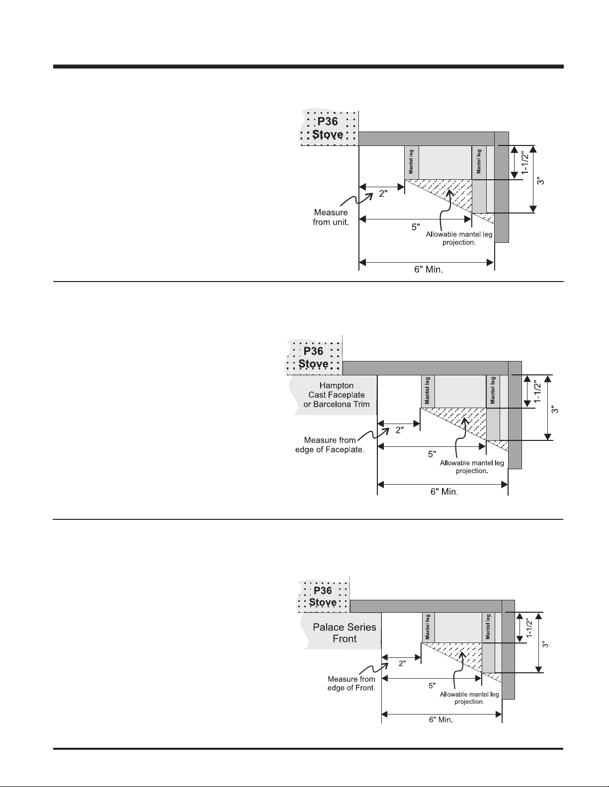
REGENCY MANTEL LEG CLEARANCES
Combustible mantel leg clearances as per diagram:
HAMPTON & BARCELONA TRIM
MANTEL LEG CLEARANCES
INSTALLATION
Maximum 1-1/2" projection
at 2" minimum clearance.
Combustible mantel leg clearances as per diagram:
Hampton Cast Faceplate Width: 43-1/4"
Barcelona Trim Width: 40"
PALACE SERIES MANTEL LEG CLEARANCES
Combustible mantel leg clearances as per diagram:
Kensington Front Width: 42-5/8"
Balmoral Front Width: 40-5/8"
Westminster Front Width: 40-5/8"
Maximum 1-1/2" projection
at 2" minimum clearance.
Maximum 1-1/2" projection
at 2" minimum clearance.
FPI P36D Zero Clearance Direct Vent Gas Fireplace 15
INSTALLATION
17-1/8"
3-1/2"
4"
2"
40-1/2"
36”
32-1/2"
10" dia. hole
through wall
for Flex
or for DuraVent
1/2"
Drywall
Top Header
Opening for gas
connection
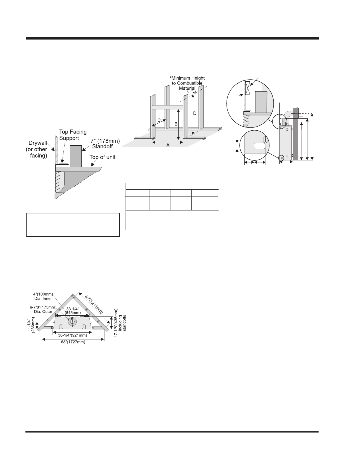
1) Determine the total thickness of facing material (e.g. drywall plus ceramic tiles) to
allow the finished surface to be flush with
the front of the unit. Total facing thickness
can vary from 1/2" (13mm) to 1-1/4" (32mm)
thick.
Install Side Nailing Strips, Top Facing
Support, and Top Standoffs before unit
is slipped into position. See page 17 for
assembly details.
2) Frame in the enclosure for the unit with
framing material. The framed opening is
37-1/4" high x 36-1/4" wide x 17-3/8" deep
(946mm high x 921mm wide x 441mm deep).
FRAMING AND
FINISHING
NOTE: See next page for important
Barcelona and Palace Series framing
note.
Framing Dimensions
A B C D
36-1/4" 37-1/4" 17-3/8" 46-1/2"*
921mm 946mm 441mm 1181mm*
* 'D' is Minimum height to combustible materials
including the Minimum 2-1/2" (64mm) Top
clearance to the Horizontal Vent.
3) For exterior walls, insulate the enclosure to
the same degree as the rest of the house,
apply vapour barrier and drywall, as per
local installation codes. (Do not insulate
the fireplace itself.)
4) The top of the unit must not be closer than
32" (813mm) to the ceiling.
Note: 40-1/2" (1029mm) is the minimum
height for both flex termination or
Simpson Dura-Vent venting.
Note: The unit does not have to be com-
pletely enclosed in a chase. The
clearance on top of the unit is 0" to
the standoffs so combustible
building materials can be laid directly on top of the standoffs. You
must maintain clearance from the
vent to combustible materials for
flex, see Vent Clearances.
5) Use steel studs for framing where the
1-1/2" (38mm) clearance from the vent to
combustible material cannot be maintained,
e.g. front top header.
16
FPI P36D Zero Clearance Direct Vent Gas Fireplace
INSTALLATION
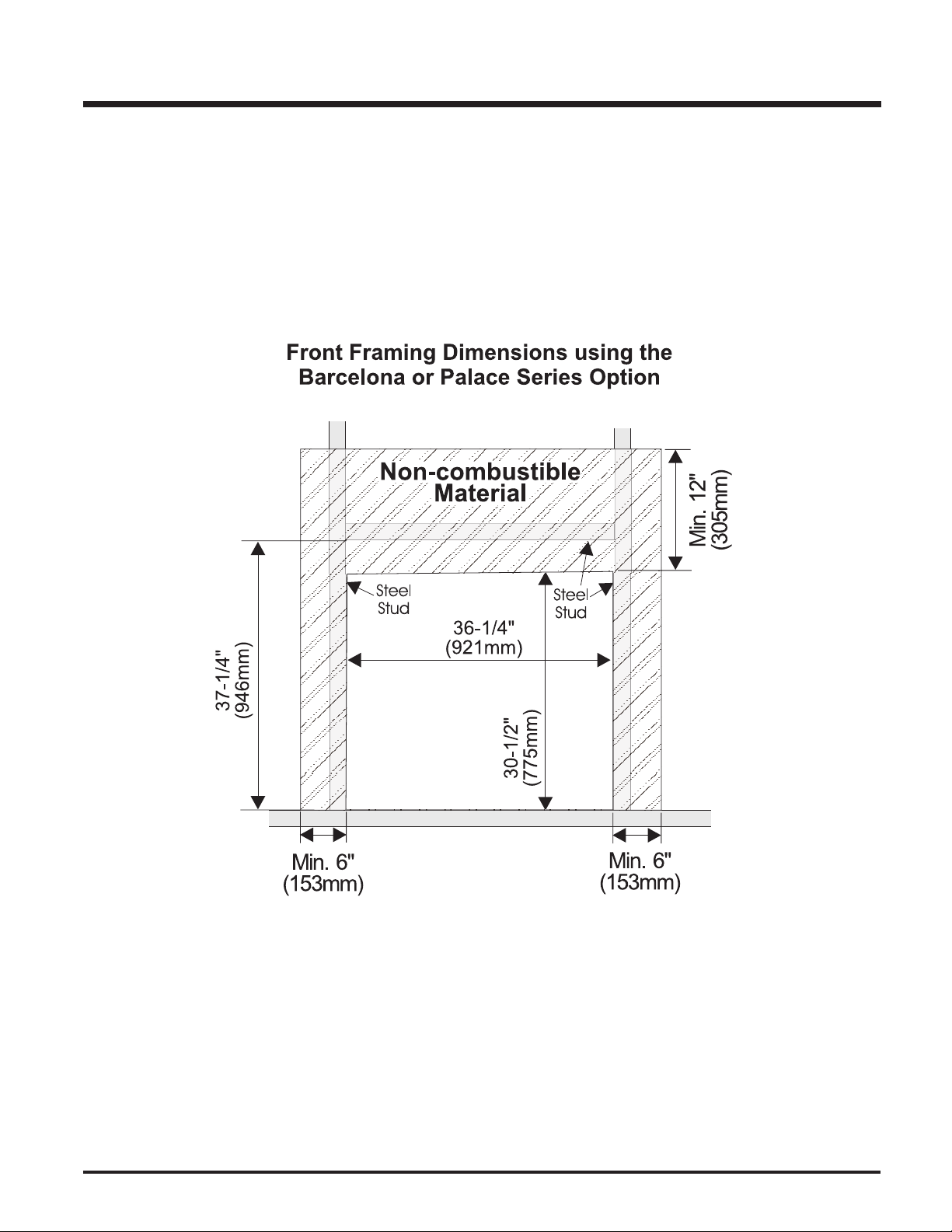
BARCELONA & PALACE SERIES FRAMING NOTE
When installing the optional Barcelona Front or Palace Series, a non-combustible material 12" (305mm) above the unit and 6" (153mm) on each
side must be used. See diagram 1.
The Barcelona Front and Palace Series also requires steel stud framing above and on each side of the unit. See diagram 1.
Diagram 1
FPI P36D Zero Clearance Direct Vent Gas Fireplace 17
INSTALLATION
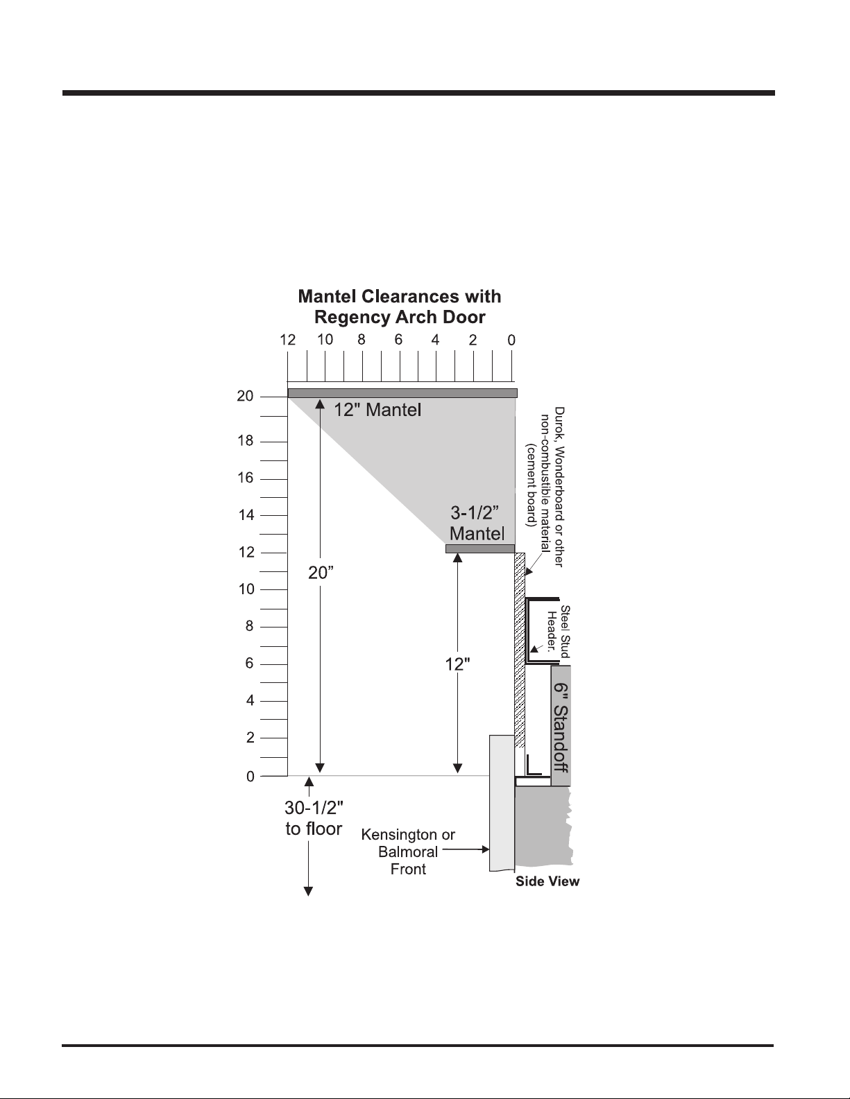
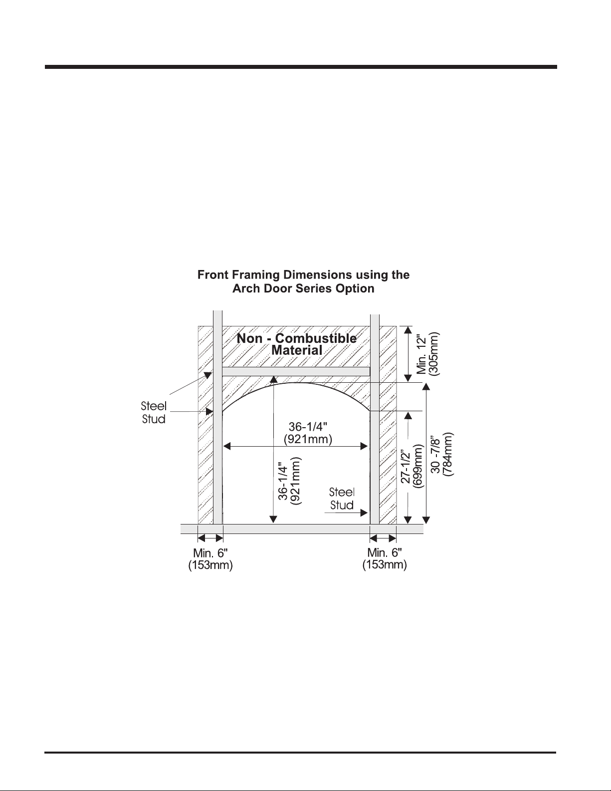
ARCH DOOR SERIES FRAMING NOTE
When installing the optional Arch Door Series, a non-combustible material 12" (305mm) above the unit and 6" (153mm) on each side must be used.
See diagram 2.
The Arch Door Series also requires steel stud framing above and on each side of the unit. See diagram 2.
18
FPI P36D Zero Clearance Direct Vent Gas Fireplace
INSTALLATION
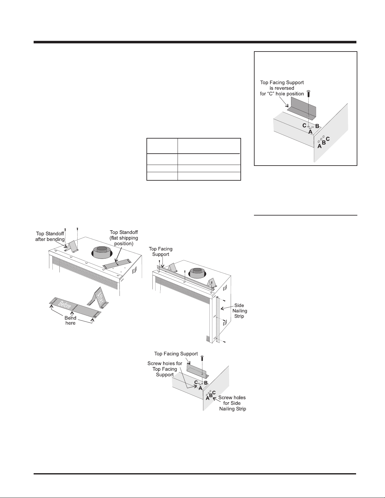
UNIT ASSEMBLY
PRIOR TO
INSTALLATION
The Top Facing Support, the Side Nailing Strips
and the 2 Top Standoffs must be correctly
positioned and attached to the top before unit
is slipped into position.
Top Standoff Assembly
The top standoffs are shipped in a flat position
and must be folded into shape and attached.
1) Remove the standoffs from the fireplace
top.
2) Take each standoff and bend into the correct shape. Bend up at the bend lines until
the screw holes in the standoff and the prepunched screw holes on the fireplace top
line up.
3) Attach the standoff securely to the top with
2 screws per standoff (on opposite corners).
Top Facing Support and
Side Nailing Strips
Determine the total thickness of facing material
(e.g. drywall plus ceramic tiles) to allow the
finished surface to be flush with the front of the
unit. Total facing thickness can vary from 1/2"
(13mm) to 1-1/4" (32mm) thick.
The Top Facing Support & Side Nailing Strips
can be mounted in 3 different positions depending on the thickness of the facing material.
Screw Facing Material
Position Depth
A 1/2" / 13mm
B 7/8" / 22mm
C* 1-1/4" / 32mm
* For "C" screw position the top facing support
is reversed.
1) Mount Top Facing Support using the 3
supplied screws into the three pre-punched
screw holes on the top front of the unit. Use
hole positions A, B, or C depending on your
facing depth.
"C" Screw Position:
For a facing material depth of 1-1/4"
(32mm), the top facing support must be
reversed.
2) Use the same screw hole position for the
Side Nailing Strips as was used for the Top
Facing Support. Attach each side nailing
strip using 3 screws.
VENTING
INTRODUCTION
The P36D uses the "balanced flue" technology
Co Axial system. The inner liner vents products
of combustion to the outside while the outer liner
draws outside combustion air into the combustion chamber thereby eliminating the need to use
heated room air for combustion and losing warm
room air up the chimney.
Not e : These flue pipes must not be con-
nected to any other appliance.
The gas appliance and vent system must be
vented directly to the outside of the building, and
never be attached to a chimney serving a
separate solid fuel or gas burning appliance.
Each direct vent gas appliance must use it's
own separate vent system. Common vent systems are prohibited.
FPI P36D Zero Clearance Direct Vent Gas Fireplace 19
.
B
B
B
B
A
C
V
V
V
V
V
V
V
A
A
V
Fixed
Fixed
Openable
Closed
Closed
Openable
N
L
B
E
B
M
D
F
K
H
j
Vertical
Termination
V
Vent terminal
Area where terminal is not permited
A
Air supply outlet
24"
V
A
G
Inside
corner detail
V
24"
18"
Vertical
Termination
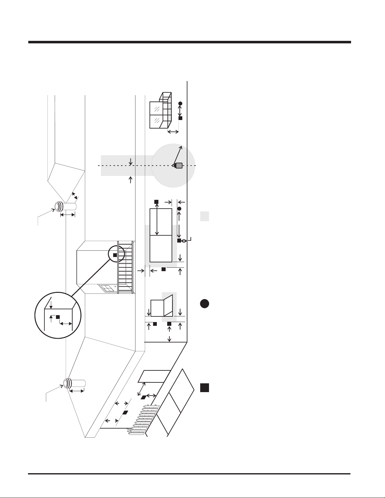
INSTALLATION
EXTERIOR VENT TERMINATION LOCATIONS
the centerline of the regulator.
any other appliance *(12"/30cm)
*(min. 84"/2.1m)
H = Not to be installed above a meter/regulator assembly within (3'/90cm) horizontally from
J= Clearance to service regulator vent outlet *(min. 36"/90cm)
K= Clearance to non-mechanical air supply inlet to building or the combustion air inlet to
L= Clearance to a mechanical air supply inlet *(min. 72"/1.8m)
M= Clearance above paved sidewalk or a paved driveway located on public property
N= Clearance under veranda, porch, deck, or balcony *(min. 12"/30cm)
20
distance of (24"/60cm) from the centerline of the terminal (min. 18"/46cm) check with
local code.
Dura-Vent Termination Cap (14"/36cm)
Vent Termination Cap (12"/30cm)
A= Clearance above grade, veranda, porch, deck, or balcony *(min. 12"/30cm)
B= Clearance to window or door that may be opened *(12"/30cm)
C= Clearance to permanently closed window *(min. 12"/30cm)
D= Vertical clearance to ventilated soffit located above the terminal within a horizontal
E= Clearance to unventilated soffit (min. 15"/38cm)
F= Clearance to outside corner: with AstroCap Termination Cap (min. 6"/15cm), with
G= Clearance to inside corner: with AstroCap Termination Cap (min. 6"/15cm), with Dura-
FPI P36D Zero Clearance Direct Vent Gas Fireplace
Note:
- A vent shall not terminate directly above a sidewalk or paved driveway which is located between two single family dwellings and serves both dwellings.
- Only permitted if veranda, porch, deck, or balcony is fully open on a minimum of two sides beneath the floor.
- If the vent termination is accessible, a certified guard shall be installed.
* As specified in CGA B149 Installation Code. Note: Local codes or regulations may require different clearances.
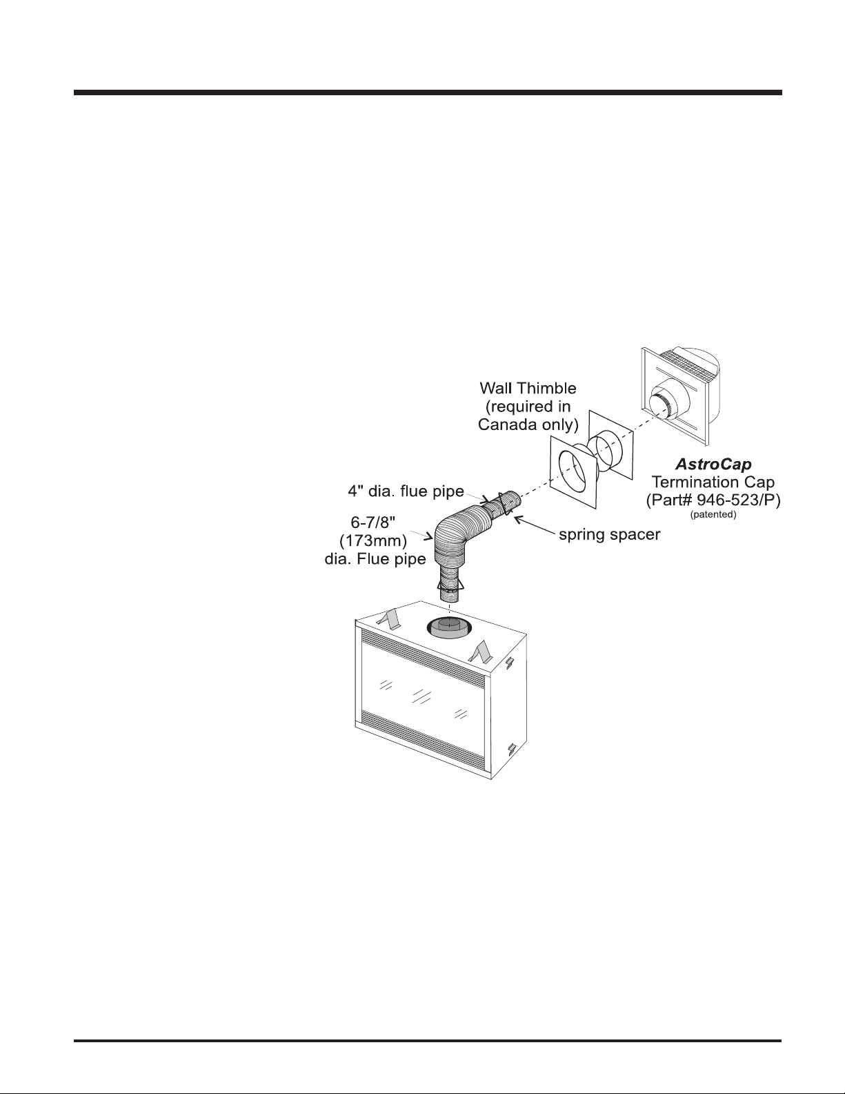
INSTALLATION
VENTING
FPI Direct Vent System (Flex) Horizontal
Terminations Only
These venting systems, in combination with the P36D Direct Vent Gas Fireplace, have been tested and listed as a direct vent heater system by
Warnock Hersey. The location of the termination cap must conform to the requirements in the Vent Terminal Locations diagram on page 20.
FPI Direct Vent (Flex) System Termination Kit (Part # 946-515) includes all the parts needed to install the P36D with a maximum
run of 4 feet.
1) 6-7/8" dia. flexible liner (4 ft. length)
2) 4" dia. flexible liner (4 ft. length)
3) spring spacers (4)
4) thimble (2)
5) AstroCap termination cap (1)
6) screws (12)
7) tube of Mill Pac (1)
8) plated screws (8)
9) screws #8 x 1-1/2" Drill Point, Stainless Steel (4)
If longer runs are needed, the FPI Direct Vent
system (Flex) # 946-516 includes all the parts
needed to install the P36D with a maximum 10'
run.
1) 6-7/8" dia. flexible liner (10 ft. length)
2) 4" dia. flexible liner (10 ft. length)
3) spring spacers (7)
4) thimble (2)
5) AstroCap termination cap (1)
6) screws (12)
7) tube of Mill Pac (1)
8) plated screws (8)
9) screws #8 x 1-1/2" Drill Point, Stainless Steel (4)
Notes:
1) Liner sections should be continuous without any joints or seams.
2) Only Flex pipe purchased from FPI may be used for Flex installations.
FPI P36D Zero Clearance Direct Vent Gas Fireplace 21
INSTALLATION
RIGID PIPE VENTING COMPONENTS LIST
All Simpson Dura-Vent components are available directly from FPI.
Description Simpson Dura-Vent Selkirk Amerivent
Direct VentGS
6" Pipe Length, Galvanized 90 8 4DT-6 N/A
6" Pipe Length, Black 908B 4DT-6B N/A
7" Pipe Length, Galvanized N/A N/A 4 D7
7" Pipe Length, Black N/A N/A 4D7B
9" Pipe Length, Galvanized 90 7 4DT-9 N/A
9" Pipe Length, Black 907B 4DT-9B N/A
12" Pipe Length, Galvanized 906 4DT-12 4D12
12" Pipe Length, Black 906B 4DT-12B 4D12B
18" Pipe Length, Galvanized N/A 4DT-18 N/A
18" Pipe Length, Black N/A 4DT-18B N/A
24" Pipe Length, Galvanized 904 4DT-24 4D2
24" Pipe Length, Black 904B 4DT-24B 4D2B
36" Pipe Length, Galvanized 903 4DT-36 4D3
36" Pipe Length, Black 903B 4DT-36B 4D3B
48" Pipe Length, Galvanized 902 4DT-48 4D4
48" Pipe Length, Black 902B 4DT-48B 4D4B
Adjustable Length, 11"-14", Galv. 911 4DT-AJ N/A
Adjustable Length, 11"-14", Black 911B 4DT-AJB N/A
Adjustable Length, 17"-24", Black 917B N/A N/A
Adjustable Length, 7" Galvinized N/A N/A 4D7A
Adjustable Length, 7" Black N/A N/A 4D7AB
Adjustable Length, 12" Galvinized N/A N/A 4D12A
Adjustable Length, 12" Black N/A N/A 4D12AB
45O Elbow, Galvinized 945 4DT-EL45 4D45L
45O Elbow, Black 945B 4DT-EL45B 4D45LB
45O Elbow, Swivel, Galvinized 945G N/A N/A
45O Elbow, Swivel, Black 945BG N/A N/A
O
Elbow, Galvinized 990 4DT-EL90S 4D90LS
90
90O Elbow, Black 990B 4DT-EL90SB 4D90LBS
90O Elbow, Swivel, Galvinized 990G N/A N/A
90O Elbow, Swivel, Black 990BG N/A N/A
Ceiling Support 949 - n/a from FPI 4DT-CS 4DFSP
Cathedral Support Box 941 4DT-CSS 4DRSB
Wall Support/Band 988 4DT-WS/B 4DWS
Offset Support 989 - n/a from FPI 4DT-OS N/A
Wall Thimble, Black 942 4DT-WT 4DWT
Wall Thimble Support Box/Ceiling Support 940 N/A N/A
Firestop Spacer 963 4DT-FS 4DFSP
Trim Plate, Black N/A 4DT-TP 4DFPB
Brass Trim for Wall Thimble/Ceiling Support 3951 N /A N/A
Attic Insulation Shield 12" N/A N/A 4DAIS12
Attic Insulation Shield - Cold Climates 36" N/A N/A 4DAIS36
Basic Horizontal Termination Kit (A) 970 4DT-HKA 4DHTK2
Horizontal Termination Kit (B) 971 4DT-HKB 4DHTK1
Vertical Termination Kit 978 4DT-VKC 4DVTK
High Wind Vertical Cap 991 N/A N/A
High Wind Horizontal Cap 985 N/A N/A
Horizontal Square Termination Cap 9 84 4DT-HHC 4DHC
Verical Termination Cap 980 4DT-HVC 4DVC
Storm Collar 953 4DT-SC 4DSC
Adjustable Flashing, 0/12-6/12 943 4DT-AF6 4DF
Adjustable Flashing, 6/12-12/12 943S 4DT-AF12 4DF12
Vinyl Siding Standoff 950 4DT-VS N/A
Vinyl Siding Shield Plate N/A 4DT-VSP N/A
Snorkel Termination 14" 982 4DT-ST14 4D12S
Snorkel Termination 36" 981 4DT-ST36 4D36S
R
Direct-Temp
TM
Direct Vent
R
22
946-506/P Vent Guard (Optional)
510-994 Rigid Pipe Adaptor (Must use with all Rigid Piping)
640-994 U37 Rigid Pipe Adaptor
640-530/P Riser Vent Terminal
946-205 Vinyl Siding Shield for Riser Vent Terminal
946-208/P Vent Guard (Optional) - Riser Vent Terminal
946-523/P AstroCap Horizontal Cap
946-206 Vinyl Siding Standoff - AstroCap
FPI P36D Zero Clearance Direct Vent Gas Fireplace
 Loading...