

Page 1
WATERFORD
www.waterfordstoves.com
Owners &
Installation
EMERALD GAS INSERT
ZERO CLEARANCE KIT
KIT # 270-900
Tested by:
PLEASE KEEP THESE INSTRUCTIONS FOR
FUTURE REFERENCE
WARNING:
Improper installation, adjustment,
alteration, service or maintenance
can cause injury or property damage. Refer to this manual. For assistance or additional information consult an authorized installer, service
agency or the gas supplier.
FOR YOUR SAFETY
Do not store or use gasoline or other
flammable vapours and liquids in
the vicinity of this or any other appliance.
Manual
Installation and service must be performed by an authorized installer,
service agency or the gas supplier.
FPI Fireplace Products International Ltd. 6988 Venture St., Delta, B.C. Canada, V4G 1H4
FOR YOUR SAFETY
What to do if you smell gas:
!!
! Do not try to light any
!!
appliance
!!
! Do not touch any electri-
!!
cal switch: do not use
any phone in your building.
!!
! Immediately call your
!!
gas supplier from a
neighbour's phone. Follow the gas supplier's
instructions.
!!
! If you cannot reach your
!!
gas supplier, call the fire
department.
© Copyright 2004, FPI Fireplace Products
International Ltd. All rights reserved.
908-270 01/15/04
Page 2

TABLE OF CONTENTS
General Information ...................................................3
Zero Clearance Kit Specifications..............................3
Listings and Code Approvals .....................................3
Clearances to Combustibles .....................................4
Safety Decal .............................................................5
Framing.....................................................................6
Zero Clearance Kit Assembly....................................6
Assemble the Cabinet ........................................7
Attach Cabinet to Framing ................................10
Install the Insert ................................................11
Venting Introduction ................................................ 11
Simpson Dura-Vent Component List ....................... 11
Venting Arrangements - Horizontal.......................... 13
Venting Arrangements - Vertical..............................13
Horizontal Termination Installation ...........................14
Vertical Termination Installation...............................15
2
Emerald Gas Insert Zero Clearance Kit
Page 3
GENERAL INFORMATION
Using Kit# 270-900 you can convert the Emerald Gas Insert into a highly efficient heat producing Zero Clearance Fireplace.
This kit consists of factory built parts that require minimal assembly to form the Zero Clearance enclosure for the Emer al d
Gas Insert. The enclosure can then be fixed into a framed combustible construction, and a standard Simpson Dura-Vent
Direct Vent GS System installed on the assembly for the required venting. The insert can be installed later. The faceplate
will normally overlap on top of the finished wall.
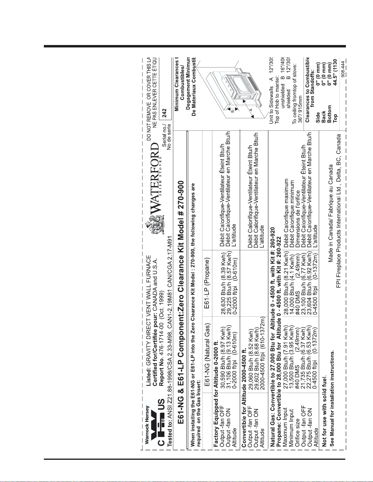
Emerald Insert Zero Clearance Kit Specifications
LISTINGS AND CODE APPROVALS
This gas component has been tested in accordance with National Safety Standards, and has been certified by Warnock Hersey
for installation and operation in the United States, and Canada as described in these Installation and Operating Instructions.
Check with your local building code agency before you begin your installation to ensure compliance with local codes, including
the need for "permits" and follow-up inspections. If any problems are encountered regarding code approvals, or if you wish
clarification on any of the instructions contained here, contact your local dealer.
Emerald Gas Insert Zero Clearance Kit
3
Page 4
INSTALLATION
CLEARANCES TO COMBUSTIBLES
The clearances for the Zero Clearance Kit are 0" to combustibles (back, side and floor) but when planning your installation
review the clearances required for the Insert (see below) after it is installed in the Zero Clearance Kit.
Warning: Combustible facing materials must not extend inside the 1/2" (13mm) lip at the edge of the face panels.
Any non-combustible facing materials (such as ceramic tile or masonry face brick) up to 1-1/2" (38mm) thick may be used
to finish the area inside the 1/2" (13mm) lip on the face panels. Non-combustible tile backer board such as Wonderboard or
Durock , or metal lath or screen may be fastened directly to the front of the face panels to provide a base for attaching facing
materials if needed. The Zero Clearance Kit must be installed on a flat, solid, continuous surface (e.g. wood, metal, concrete).
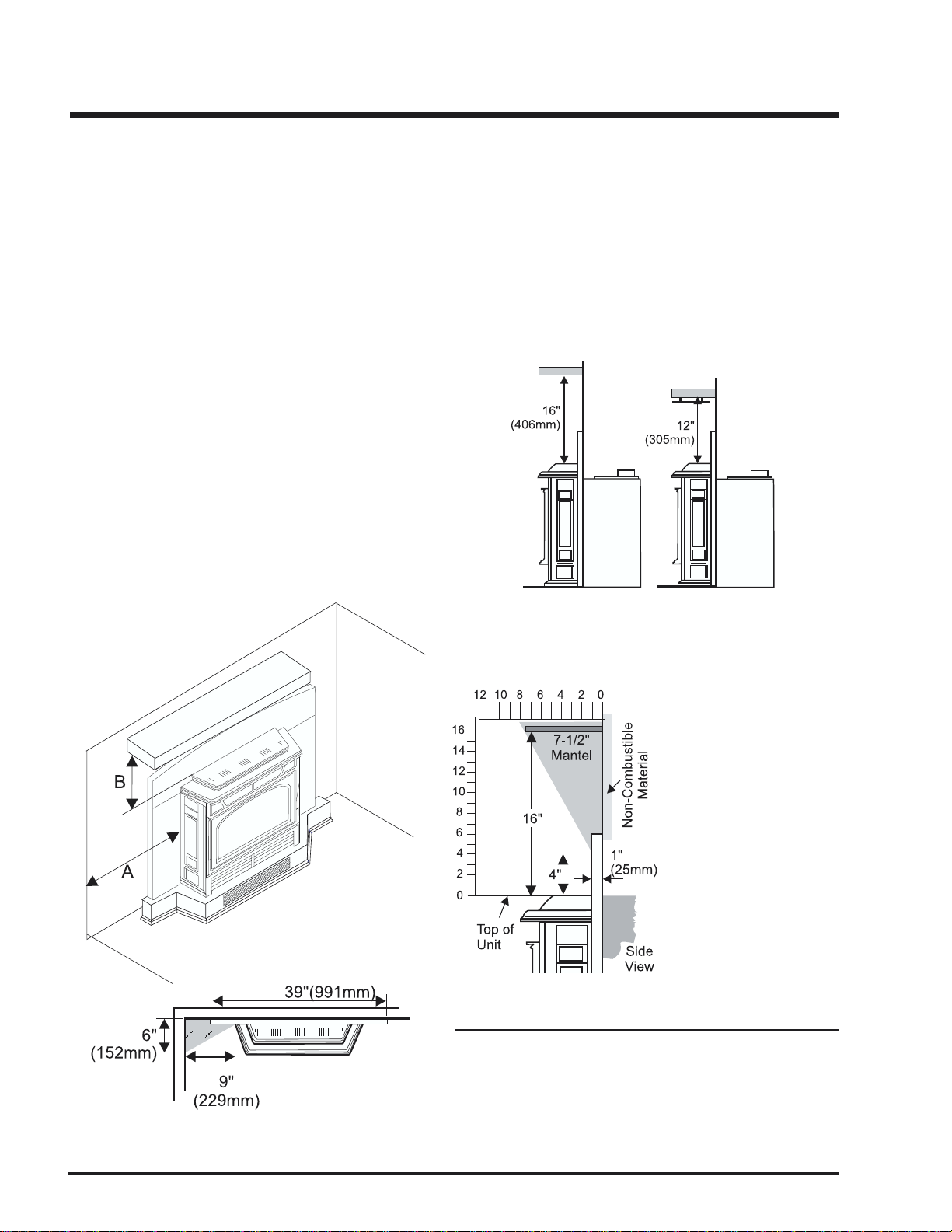
Emerald Insert Clearances to Combustibles:
From Unit
Sides A 12" / 305 mm
Unit to Unprotected Mantel B 16" / 406 mm
(see Mantel clearance diagram below)
Unit to Protected Mantel* C 12" / 305mm
In addition to these clearances, adequate accessibility
clearance for servicing and proper operation must be maintained.
Do not in any way obstruct the combustion air inlets that are
located on the front of the heater.
Clearance from top of hob to
mantel and combustible trim,
unshielded.
Combustibles are permitted within
the shaded area.
Clearance from top of hob to
mantel and combustible trim,
shielded.
*Mantel shield must have a
1" (25mm) air space between the mantel and shield
and a 1" (25mm) gap between on the back of the shield
and the facing.
Floor Protection
If the appliance is installed in a fireplace that is elevated 5"
(127mm) or higher (i.e., a Waterford Zero Clearance Cabinet,
Combustibles are permitted within
the shaded area, on either side.
4
zero clearance fireplace, brick plinth, etc.), no floor protection is
required in front of the appliance.
Emerald Gas Insert Zero Clearance Kit
Page 5
This is a copy of the label that accompanies each Waterford E61 Zero Clearance Kit #270-900. We have printed a
copy of the contents here for your review. The safety label is located on the
top panel.
NOTE: Waterford units are constantly
being improved. Check the label on
the unit and if there is a difference, the
label on the unit is the correct one.
SAFETY LABEL
Emerald Gas Insert Zero Clearance Kit
5
Page 6

INSTALLATION
EXTERIOR VENT TERMINAL LOCATIONS
18"
24"
Vertical
Termination
A
L
V
N
j
H
V
B
V
B
B
Closed
Fixed
Openable
V
A
Area where terminal is not permited
horizontally from the centerline of the regulator.
min 36"/90cm)
air inlet to any other appliance *(12"/30cm)
J= Clearance to service regulator vent outlet *(Canada: min. 72"/1.8m, USA:
K= Clearance to non-mechanical air supply inlet to building or the combustion
property *(min. 84"/2.1m)
L= Clearance to a mechanical air supply inlet *(min. 72"/1.8m)
M = **Clearance above paved sidewalk or a paved driveway located on public
N= Clearance under veranda, porch, deck, or balcony *(min. 12"/30cm)***
A
K
V
B
Air supply outlet
A
Openable
Fixed
Closed
C
V
.
M
V
B
V
F
Vent terminal
V
horizontal distance of (24"/60cm) from the centerline of the terminal (min.
18"/46cm) check with local code.
A = Clearance above grade, veranda, porch, deck, or balcony *(min. 12"/30cm)
B= Clearance to window or door that may be opened *(12"/30cm)
C= Clearance to permanently closed window *(min. 12"/30cm)
D= Vertical clearance to ventilated soffit located above the terminal within a
15cm), with Dura-Vent Termination Cap (min.12"/30cm)
with Dura-Vent Termination Cap (min.12"/30cm)
E= Clearance to unventilated soffit (min. 12"/30cm)
F= Clearance to outside corner: with AstroCap Termination Cap (min. 6"/
G= Clearance to inside corner: with AstroCap Termination Cap (min. 6"/15cm),
H= Not to be installed above a meter/regulator assembly within (3'/90cm)
Note: * As specified in CGA B149 Installation Code. Note: Local codes or regulations may require different clearances.
**A vent shall not terminate directly above a sidewalk or paved driveway which is located between two single family dwellings and serves both dwellings.
***Only permitted if veranda, porch, deck, or balcony is fully open on a minimum of two sides beneath the floor.
Emerald Gas Insert Zero Clearance Kit
G
corner detail
Vertical
Termination
V
A
B
24"
E
V
D
Inside
6
Page 7

INSTALLATION
FRAMING
1) The cabinet face panels have a 1/2" lip to define the zones for combustible
and non-combustible facing materials: outside the lip, any material up
to 1/2" (13mm) may be used; inside the lip, only non-combustible
materials may be used (with a maximum thickness of 1-1/2" (38mm)).
The kit may be installed directly on and/or against standard combustible
building materials.
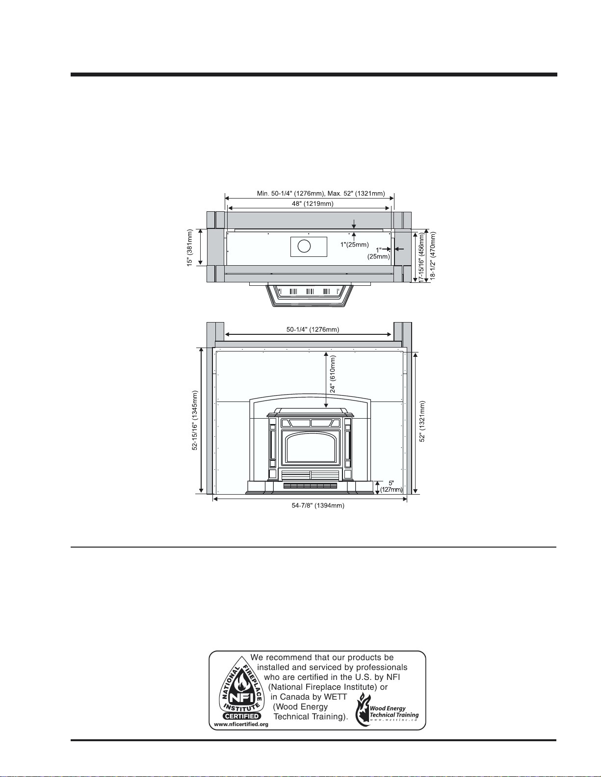
2) Frame in the enclosure for the Kit with framing material. The framed
opening for the assembled kit is 52" (1321 mm) high x 50-1/4" (1276 mm)
wide x 18-1/2" (470 mm) deep. See diagram.
If the interior of the cabinet framing is finished (with sheet rock,
for example), The dimensions given are from the inside of the
finished surfaces. The ceiling inside the framed enclosure
should be a minimum of 55-1/2" (1410mm) from the base of
the plinth.
3) For exterior walls, use a vapour barrier and insulate the
enclosure to the same degree as the rest of the house, or
according to local installation codes. In colder climates, if the heater is to be installed against an exterior wall or
chase, insulate the exterior walls according to local installation codes.
ZERO CLEARANCE KIT ASSEMBLY
Parts Included with Kit:
2 Back sections
2 Side
1 Base
1 Top
2 Front Face Side Panel
1 Front Face Top Panel
2 Top Standoffs
2 Extension Legs
1 Plinth
All pieces join together using the sheet metal screws that are
provided with the kit.
Assemble the Cabinet
1) Assemble the Sides and Base sections. The Side sections fit inside the lip of the Base section. The wider flange
on the Side section is on the front of the kit.
Secure with 2 screws on each side. Leave the 3rd screw
(closest to the rear) until the Back section is attached.
screw
Right Side
screw
Do not install the third screw until
the back panel is installed.
Base
Section
screw
screw
Base
Section
Emerald Gas Insert Zero Clearance Kit
Left Side
7
Page 8

INSTALLATION
2) Set the assembled Side and Base sections upright. Slide
the Lower Back (the section with 4 holes) down the inside
of Side flanges (make sure the 4 holes are closest to the
floor - see photo).
Secure with 2 screws on each side, and 11 screws on the
back.
3) Slide the Upper Back Section down the inside of the Side
flanges.
Secure to the Lower Back Section with 4 screws (from the
inside).
Right
Side
screw
Attach with 2 screws on the side. Repeat for Left Side
Attach with 11 screws on the side.
From the outside, secure with 2 screws on each side.
8
Emerald Gas Insert Zero Clearance Kit
Page 9

INSTALLATION
Secure with 6 screws on the back. Leave the top screw
holes until the top is attached.
4) Install the Top. Hold the top so that the large vertical flange
is at the front of the cabinet and fit it down over the Side/
Back assembly. Secure the top to the assembly using 3
screws on each side and 5 through the back and 8 on top.
5) Assemble the 2 top Standoffs. The Top Standoffs are
shipped flat and must be folded at the bend lines into the
correct shape.
Attach the Right Standoff to the top using the 4 holes at the
front right of the top. Install the Left Standoff to the 4 holes
at the front left.
Emerald Gas Insert Zero Clearance Kit
Left and Right Standoffs in position and
attached with 4 screws each.
6) Assemble the flue adaptor box. Slide the flex vent pipe
over the small vent opening on the base of the adaptor box
and secure with a clamp. Repeat for the 2nd flex vent pipe.
Use silicone to seal the connection.
9
Page 10

INSTALLATION
7) Drop the Flue Adaptor assembly into the hole on the top
section and secure from the top with 4 screws.
8) Assemble the Face Panels (left, right, and top), all 3 Face
panels are installed loosely, and then attached to the
cabinet body.
Secure the Left and Right Panels to the top with 1 screw
each. Make sure that the outside edges are aligned.
Secure the flue adaptor box to the top with
4 screws from the top.
Fit the assembled Side & Top Face Panels to the front of
the cabinet and secure with 19 screws.
10
Emerald Gas Insert Zero Clearance Kit
Page 11

INSTALLATION
Attach the Cabinet to the Framing
Slide the cabinet into the frame constructed previously and
secure with nails or sheet rock screws, installing a fastener
into at least every other hole.
Warning: Combustible materials must not extend inside the
stand-offs on the side, top and rear supports. For safety
reasons do not modify or alter any components of the Kit.
Install the Insert
1) Remove the hob and surround from the top of the unit for
access into the cabinet during installation. Slide the unit
into the cabinet on top of the bottom standoffs.
2) Connect the flue and make all connections according to
the instructions in the Venting section.
Any non-combustible facing materials (such as ceramic tile
or masonry face brick) up to 1-1/2" (38mm) thick may be used
to finish the area inside the 1/2" (13mm) lip on the face panels.
Non-combustible tile backer board such as Wonderboard or
Durock , or metal lath or screen may be fastened directly to the
front of the face panels to provide a base for attaching facing
materials if needed.
If a combustible mantel is desired, it must be above the 1/2"
(13mm) lip on the Top Face panel, a minimum of 24" for the
top of the insert hob. This includes both the mantel itself and
any trim below the mantel. A completely non-combustible
mantel, such as stone, may be placed wherever desired.
3) Re-install the hob and surround.
4) Slide the Plinth into position with about 1/8" (3mm)
clearance to the bottom of the insert front and side
surround panels.
Emerald Gas Insert Zero Clearance Kit
11
Page 12

INSTALLATION
VENTING INTRODUCTION
The E61 Emerald Insert uses the "balanced flue"
technology Co Axial system. The inner liner vents products
of combustion to the outside while the outer liner draws
outside combustion air into the combustion chamber thereby eliminating the need to use heated room air for combustion and losing warm room air up the chimney.
Note: These flue pipes must not be connected to
any other appliance.
These venting systems, in combination with the E61 Insert and the
E61 Zero Clearance Kit # 230-900, have been tested and listed as
a direct vent heater system by Warnock Hersey. The location of the
termination cap must conform to the requirements in the Vent
Terminal Locations diagram on page 6.
The gas appliance and vent system must be vented directly to the outside of the building,
and never be attached to a chimney serving a separate solid fuel or gas burning appliance.
Each direct vent gas appliance must use it's own separate vent system. Common vent
systems are prohibited.
SIMPSON DURA-VENT VENTING
All Simpson Dura-Vent components are available directly from Regency.
All components available directly from Regency.
Part # Description
971 Horiz. Termination Kit includes: 90o black elbow,
wall thimble cover, horiz. square termination
cap, 24" black pipe, 11" -14" 5/8" adjustable
black pipe
970 Basic Horiz. Termination. Kit includes: 90o black
elbow, wall thimble cover, horiz. square termination cap
97 8 Vert. Termination Kit includes 0/12 - 6/12 pitch
adjustable flashing, storm collar, low profile
term. cap
908B 6" Pipe Length - Black
907B 9" Pipe Length - Black
90 6 12" Pipe Length - Galv.
906B 12" Pipe Length - Black
90 4 24" Pipe Length - Galv.
904B 24" Pipe Length - Black
90 3 36" Pipe Length - Galv.
903B 36" Pipe Length - Black
90 2 48" Pipe Length - Galv.
902B 48" Pipe Length - Black
911B 11"-14 5/8" Adjustable Pipe Length - Black
917B 17"- 24" Adjustable Length - Black
COMPONENTS LIST
Part # Description
990 90O Elbow - Galv.
990B 90O Elbow - Black
990G 90O Elbow - Swivel - Galv.
990BG 90O Elbow - Swivel - Black
99 1 High Wind Termination Cap (Vertical)
98 0 Vertical Termination Cap
98 4 Horizontal Square Termination Cap
98 5 Horizontal Square High Wind Termination Cap
94 0 Wall Thimble - Support/Box
94 1 Cathedral/Ceiling - Support/Box
3951 Brass Trim for Cathedral
963 Firestop Spacer
943 Flashing 0/12-6/12
943S Flashing 7/12-12/12
953 Storm Collar
95 0 Vinyl Siding Standoff
98 8 Wall Strap
942 Wall Thimble
Parts not supplied by Dura-Vent
946-506/P Vent Guard (Optional)
946-523 AstroCap Termination Cap
12
Emerald Gas Insert Zero Clearance Kit
Page 13

VENTING ARRANGEMENTS -
HORIZONTAL TERMINATIONS
SIMPSON DURA-VENT DIRECT VENT
GS SYSTEM
Diagram 1 shows allowable combinations of vertical run with
horizontal terminations, using one 90o elbow.
ONLY FOR USE WITH THE REDUCTION KIT TO LOWER BTU
RATING KIT# 260-920 (NATURAL GAS AT 27,000 BTU) OR KIT
# 260-922 (PROPANE AT 29,000).
(Propane & Natural Gas)
INSTALLATION
Diagram 1
Simpson Dura-Vent
4" inner diameter
6-5/8" outer diameter
A vent guard should be used whenever the termination is
lower than the specified minimum or as per local codes.
• Maintain a 1-1/4" clearance to combustibles (1-1/2"
with Flex).
• Firestops are required at each floor level and whenever
passing through a wall.
VENTING ARRANGEMENTS -
VERTICAL TERMINATIONS
SIMPSON DURA-VENT DIRECT VENT GS
SYSTEM (Propane & Natural Gas)
Diagram 2 shows allowable straight vertical with Simpson
Dura-Vent Direct Vent GS vent systems for Propane and
Natural Gas.
• Firestops are required at each floor level and whenever
passing through a wall.
• Maintain a 1-1/4" clearance to combustibles
Diagram 2
Emerald Gas Insert Zero Clearance Kit
13
Page 14

INSTALLATION
HORIZONTAL INSTALLATIONS
Install the vent system according to the manufacturer's
instructions included with the components.
1) Set the unit in its desired location. Check to determine if
wall studs or roof rafters are in the way when the venting
system is attached. If this is the case, you may want to
adjust the location of the unit. Rough in the gas preferably
on the right side of the unit and the electrical (junction
block is on the left side) on the left.
2) Direct Vent pipe and fittings are designed with special
twist-lock connections to connect the venting system to
the appliance flue outlet.
3) Put a bead of silicone inside the outer section of the
adapter and a bead of Mill-Pac on the inner collar. Slip the
adapter over the existing inner and outer flue collar and
fasten to the outer collar only with the 3 supplied screws
(drilling pilot holes will make this easier). Level the
fireplace and fasten it to the framing using nails or screws
through the nailing strips.
4) Assemble the desired combination of pipe and elbow to
the appliance adaptor and twist-lock for a solid connection.
Note:
a)Twist-lock procedure: Four indentations, located on
the female ends of pipes and fittings, are designed to
slide straight onto the male ends of adjacent pipes and
fittings, by orienting the four pipe indentations so they
match and slide in to the four entry slots on the male
ends, Dia. 1. Push the pipe sections completely together, then twist-lock one section clockwise approximately
one-quarter turn, until the two sections are fully locked.
The female locking lugs will not be visible from the
outside, on the Black Pipe or fittings. They may be
located by examining the inside of the female ends.
Dia. 2
Note:
a) The horizontal run of vent must be level, or have a 1/
4 inch rise for every 1 foot of run towards the termination. Never allow the vent to run downward. This could
cause high temperatures and may present the possibility of a fire.
b) The location of the horizontal vent termination on an
exterior wall must meet all local and national building
codes, and must not be blocked or obstructed. For
External Vent Terminal Locations, see diagram in the
manual.
6) The arrow on the vent cap should be pointing up. Insure
that the 1-1/2" clearances to combustible materials are
maintained (Dia. 3). Install the termination cap.
Note: Apply sealant "Mill-
Pac" to inner pipe
and high temperature silicone sealant
to outer pipe on every twist-lock joint.
Dia. 1
b) Horizontal runs of vent must be supported every three
feet. Wall straps are available for this purpose.
5) Mark the wall for a 10" x 10" square hole. The center of the
square hole should line up with the centerline of the
horizontal pipe. Cut and frame the 10 inch square hole in
the exterior wall where the vent will be terminated. If the
wall being penetrated is constructed of non-combustible
material, i.e. masonry block or concrete, a 7"(178mm)
dia. (7-1/2"(191mm) dia. for flex) hole is acceptable.
Diagram 2.
14
Dia. 3
The four wood screws provided should be replaced with
appropriate fasteners for stucco, brick, concrete, or other
types of sidings.
Emerald Gas Insert Zero Clearance Kit
Page 15

INSTALLATION
Note: If installing termination on a siding covered wall, a
vinyl siding standoff or furring strips must be used to
ensure that the termination is not recessed into the
siding.
7) Before connecting the horizontal run of vent pipe to the
vent termination, slide the Wall Thimble (Part # 620-926)
over the vent pipe.
8) Slide the appliance and vent assembly towards the wall
carefully inserting the vent pipe into the vent cap assembly. It is important that the vent pipe extends into the vent
cap sufficient distance so as to result in a minimum pipe
overlap of 1-1/4 inches. Secure the connection between
the vent pipe and the vent cap by attaching the two sheet
metal strips extending from the vent cap assembly into
the outer wall of the vent pipe. Use the two sheet metal
screws provided to connect the strips to the pipe section.
See Dia. 4.
VERTICAL TERMINATION
1) Maintain the 1-1/2" clearances (air spaces) to combus-
tibles when passing through ceilings, walls, roofs, enclosures, attic rafter, or other nearby combustible surfaces. Do not pack air spaces with insulation. Check page
13 for the maximum vertical rise of the venting system.
2) Set the gas appliance in its desired location. Drop a
plumb bob down from the ceiling to the position of the
appliance flue exit, and mark the location where the vent
will penetrate the ceiling. Drill a small hole at his point.
Next, drop a plumb bob from the roof to the hole previously
drilled in the ceiling, and mark the spot where the vent will
penetrate the roof. Determine if ceiling joists, roof rafters
or other framing will obstruct the venting system.
Dia. 4
9) Install wall thimble in the center of the 10" square and
attach with wood screws (Dia 5).
Dia. 5
Emerald Gas Insert Zero Clearance Kit
15
Page 16

Printed in Canada
 Loading...