

Page 1
918-432a
09/06/05
6988 Venture St., Delta, BC
Canada, V4G 1H4
What to do if you smell
gas:
appliance
Do not touch any electri-
cal switch: do not use
any phone in your build-
Immediately call your
ga s supplier fr om a
If you cannot reach your
gas supplier, call the fi re
department.
WARNING:
alteration, service or maintenance
can cause injury or property damage.
or additional information consult an
authorized installer, service agency
or the gas supplier.
fl ammable vapours and liquids in
the vicinity of this or any other ap-
ZERO CLEARANCE KIT
Page 2

2
TABLE OF CONTENTS
GAS INSERT ZERO CLEARANCE KIT
PAGE
..........................................................................
3
.....................................
3
..............................................................
4
........................................................
.............................................................................................
Zero Clearance Kit Assembly
.............................................
Assemble the Cabinet
........................................................
Attach the Cabinet to the Framing
...................................
Install the Insert
.............................................................
Venting Introduction
.......................................................................
Simpson Dura-Vent Components List
............................
Page 3
This kit consists of factory built parts that require minimal assembly to form the Zero Clearance enclosure for the E33 Gas
overlap on top of the fi nished wall.
LIP
Page 4
4
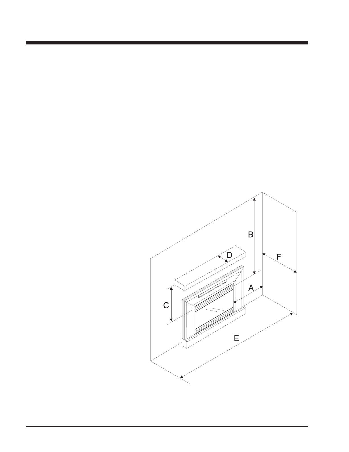
The clearances for the Zero Clearance Kit are 0" to combustibles (back, side and fl oor) but when planning your installation
Warning: Combustible facing materials must not extend inside the 1/2" (13mm) lip at the edge of the face panels.
Any non-combustible facing materials (such as ceramic tile or masonry face brick) up to 1-1/2" (38mm) thick may be used to
fi nish the area inside the 1/2" (13mm) lip on the face panels. Non-combustible tile backer board such as Wonderboard or Durock
From Unit
Sides
12" (305mm)
Ceiling
47" (1194mm)
C
23" (584mm)
3-1/2" (89mm)
Alcove Width
76" (1930mm)
Alcove Depth
36" (914mm)
* Alcove side wall must have a minimum of 12" (305mm)
clearance on one side.
Page 5
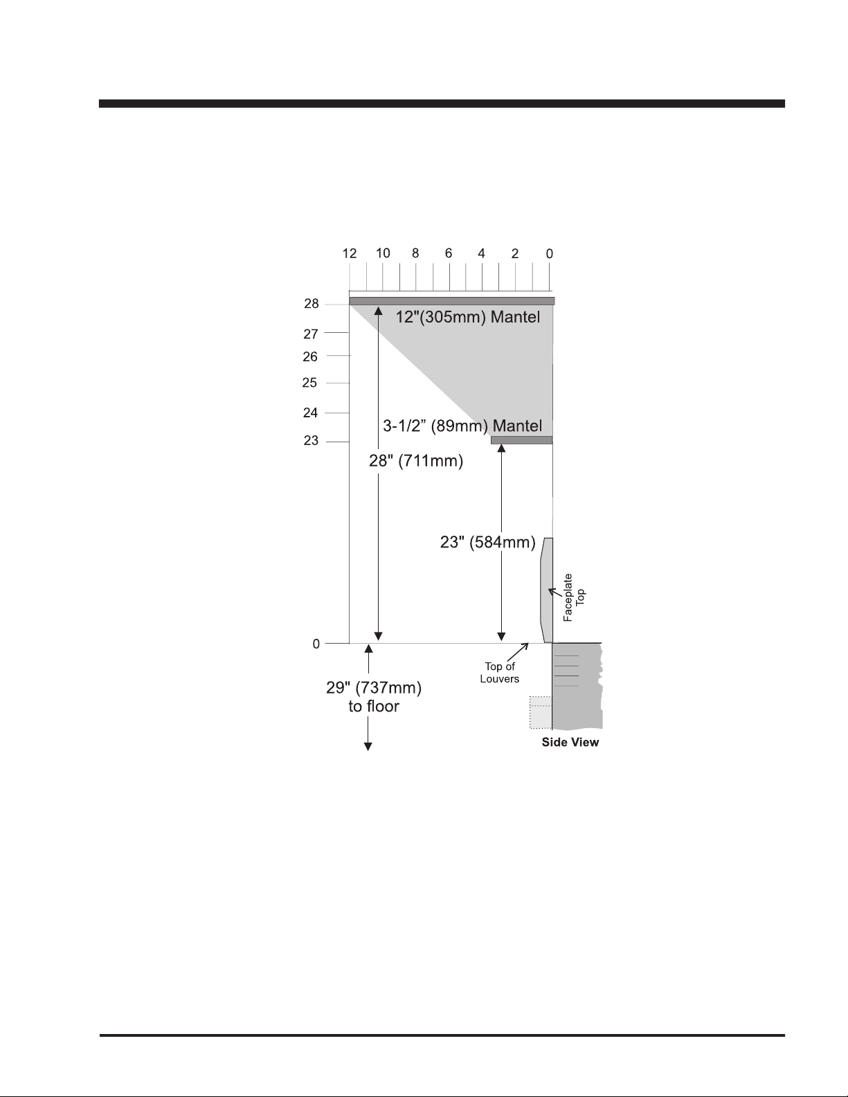
Combustible mantel clearances from top of unit are shown in the above diagrams.
with a non-combustible board.
Page 6

Right Side
Base
screw
screw
Left Side
Base
screw
screw
Do not install the third screw until
The cabinet face panels have a 1/2" (13mm) lip to defi ne the zones for
combustible and non-combustible facing materials: outside the lip, any
tible materials may be used (with a maximum thickness of 1-1/2" (38mm)).
The kit may be installed directly on and/or against standard combustible
2)
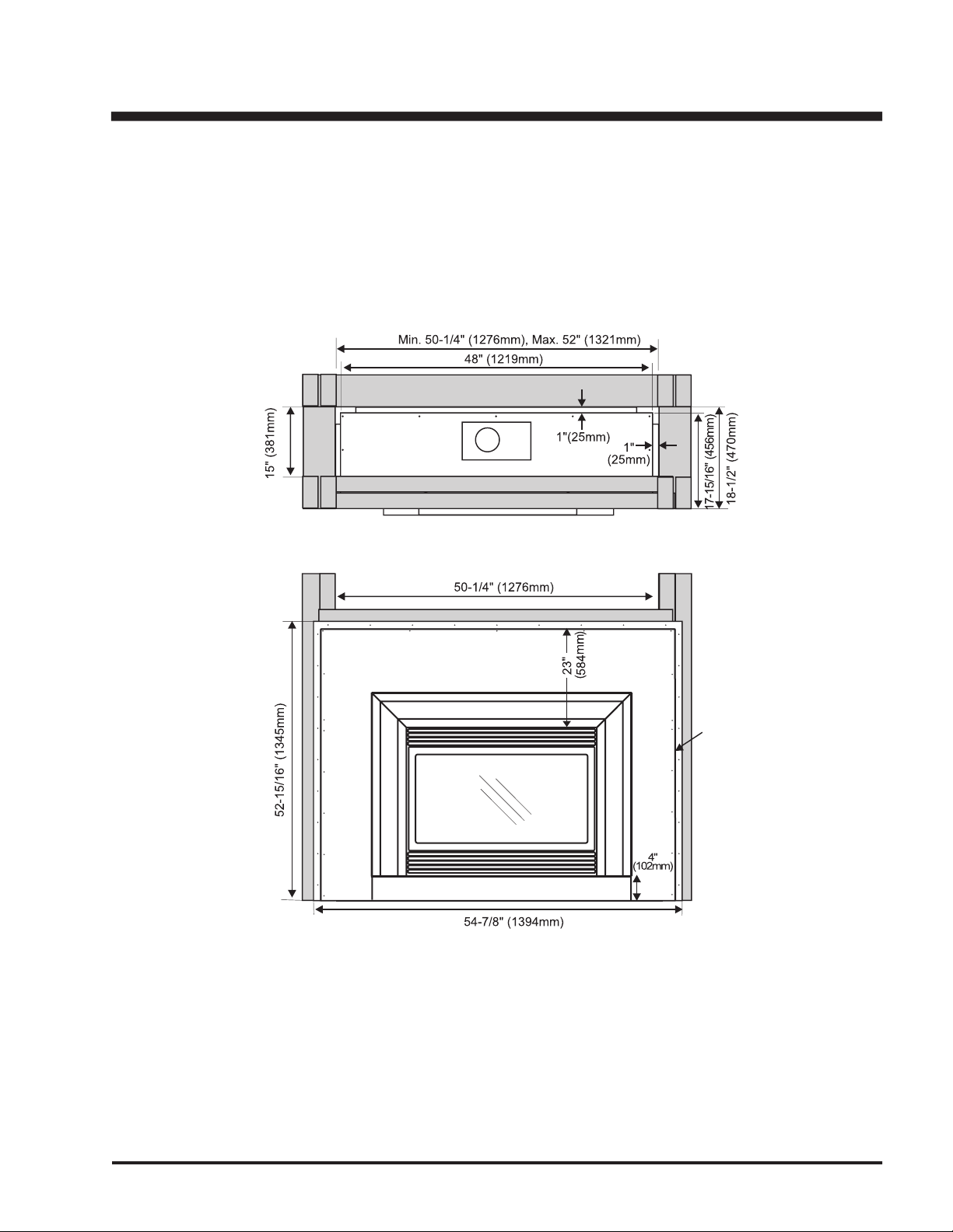
Frame in the enclosure for the Kit with framing material. The framed
opening for the assembled kit is 52" (1321 mm) high x 50-1/4" (1276
If the interior of the cabinet framing is fi nished (with sheet rock,
for example), The dimensions given are from the inside of the
fi nished surfaces. The ceiling inside the framed enclosure
should be a minimum of 55-1/2" (1410mm) from the base.
3)
For exterior walls, use a vapour barrier and insulate the enclo-
sure to the same degree as the rest of the house, or according
to local installation codes. In colder climates, if the heater is
to be installed against an exterior wall or chase, insulate the exterior walls according to local installation codes.
ZERO CLEARANCE KIT ASSEMBLY
2 Back sections
2 Side
2 Front Face Side Panel
2 Top Standoffs
2 Extension Legs
All pieces join together using the sheet metal screws that are
Assemble the Cabinet
fi t inside the lip of the Base section. The wider fl ange on
the Side section is on the front of the kit.
Secure with 2 screws on each side. Leave the 3rd screw
Page 7

7
Secure to the Lower Back Section with 4 screws (from the
From the outside, secure with 2 screws on each side.
See Below.
2) Set the assembled Side and Base sections upright. Slide
the Lower Back (the section with 4 holes) down the
of Side fl anges (make sure the 4 holes are closest to the
fl oor - see photo).
Right
screw
Attach with 2 screws on the side. Repeat for Left Side
Attach with 11 screws on the sides and bottom.
3) Slide the Upper Back Section down the
of the Side
fl anges.
screw
screw
Side
Page 8

5) Assemble the 2 top Standoffs. The Top Standoffs are
shipped fl at and must be folded at the bend lines into the
correct shape.
Attach the Right Standoff to the top using the 4 holes at
the front right of the top. Install the Left Standoff to the 4
Secure with 6 screws on the back. Leave the top screw
4) Install the Top. Hold the top so that the large vertical
fl ange is at the front of the cabinet and fi t it down over
the Side/Back assembly. Secure the top to the assembly
8 on top.
Page 9

8) Assemble the Face Panels (left, right, and top), all 3 Face
cabinet body.
the cabinet and secure with 19 screws.
7) Drop the Flue Adaptor assembly into the hole on the top
section.
4 screws from the top.
a) Secure the Left and Right Panels to the top with 1 screw
each. Make sure that the outside edges are aligned.
6) Assemble the fl ue adaptor box. Slide the fl ex vent pipe
over the small vent opening on the base of the adaptor
EXHAUST
Page 10

offs.
2) Connect the fl ue and make all connections according to
the instructions in the Venting section.
3) Install the Surround and Hearth Trim.
Attach the Cabinet to the Framing
Slide the cabinet into the frame constructed previously and
secure with nails or sheet rock screws, installing a fastener
Warning: Combustible materials must not extend inside
the stand-offs on the side, top and rear sup
ports. For safety reasons do not modify or
alter any components of the Kit.
51-7/8"
(1318mm
)
52-3/4"
(1340mm)
Any non-combustible facing materials (such as ceramic tile
or masonry face brick) up to 1-1/2" (38mm) thick may be
directly to the front of the face panels to provide a base for
attaching facing materials if needed.
wherever desired.
Page 11

All components available directly from Regency.
978 Vert. Termination Kit includes 0/12 - 6/12 pitch
adjustable fl ashing, storm collar, low profi le term.
cap
908B 6" Pipe Length - Black
907B 9" Pipe Length - Black
906 12" Pipe Length - Galv.
906B 12" Pipe Length - Black
904 24" Pipe Length - Galv.
904B 24" Pipe Length - Black
903 36" Pipe Length - Galv.
903B 36" Pipe Length - Black
902 48" Pipe Length - Galv.
902B 48" Pipe Length - Black
911B 11"-14 5/8" Adjustable Pipe Length - Black
917B 17"- 24" Adjustable Length - Black
991 High Wind Termination Cap (Vertical)
980 Vertical Termination Cap
940 Wall Thimble - Support/Box
941 Cathedral/Ceiling - Support/Box
3951 Brass Trim for Cathedral
963 Firestop Spacer
943 Flashing 0/12-6/12
943S Flashing 7/12-12/12
953 Storm Collar
988 Wall Strap
942 Wall Thimble
All Simpson Dura-Vent components are available directly from Regency.
VENTING INTRODUCTION
The E33 Insert uses the "balanced fl ue" technology Co.
Axial system. The inner liner vents products of combustion
to the outside while the outer liner draws outside combustion
air into the combustion chamber thereby eliminating the need
to use heated room air for combustion and losing warm room
air up the chimney.
Note: These fl ue pipes must not be connected to any
The location of the termination cap must conform to the require-
on page 4.
The gas appliance and vent system must be vented directly to
the outside of the building, and never be attached to a chimney
serving a separate solid fuel or gas burning appliance. Each
direct vent gas appliance must use it's own separate vent
system. Common vent systems are prohibited.
Note: The unit cannot be terminated horizontally,
only vertically.
Page 12

_________________________________________________
_________________________________________________
_________________________________________________
_________________________________________________
_________________________________________________
_________________________________________________
_________________________________________________
_________________________________________________
_________________________________________________
_________________________________________________
_________________________________________________
_________________________________________________
_________________________________________________
_________________________________________________
_________________________________________________
_________________________________________________
_________________________________________________
_________________________________________________
_________________________________________________
_________________________________________________
_________________________________________________
_________________________________________________
_________________________________________________
_________________________________________________
Page 13

_________________________________________________
_________________________________________________
_________________________________________________
_________________________________________________
_________________________________________________
_________________________________________________
_________________________________________________
_________________________________________________
_________________________________________________
_________________________________________________
_________________________________________________
_________________________________________________
_________________________________________________
_________________________________________________
_________________________________________________
_________________________________________________
_________________________________________________
_________________________________________________
_________________________________________________
_________________________________________________
_________________________________________________
_________________________________________________
_________________________________________________
_________________________________________________
Page 14

_________________________________________________
_________________________________________________
_________________________________________________
_________________________________________________
_________________________________________________
_________________________________________________
_________________________________________________
_________________________________________________
_________________________________________________
_________________________________________________
_________________________________________________
_________________________________________________
_________________________________________________
_________________________________________________
_________________________________________________
_________________________________________________
_________________________________________________
_________________________________________________
_________________________________________________
_________________________________________________
_________________________________________________
_________________________________________________
_________________________________________________
_________________________________________________
Page 15

_________________________________________________
_________________________________________________
_________________________________________________
_________________________________________________
_________________________________________________
_________________________________________________
_________________________________________________
_________________________________________________
_________________________________________________
_________________________________________________
_________________________________________________
_________________________________________________
_________________________________________________
_________________________________________________
_________________________________________________
_________________________________________________
_________________________________________________
_________________________________________________
_________________________________________________
_________________________________________________
_________________________________________________
_________________________________________________
_________________________________________________
_________________________________________________
Page 16

© Copyright 2005, FPI Fireplace Products International Ltd. All rights reserved.
 Loading...