

Page 1
WARNING:
What to do if you smell gas:
from a neighbour's phone. Follow
E21 Gas Insert
www.regency-fi re.com
Tested by:
Installer: Please complete the details on the back cover
and leave this manual with the homeowner.
Homeowner: Please keep these instructions for future reference.
Page 2
Regency E21 Gas Fireplace Insert
You are the owner of a state-of-the-art Gas Insert by:
has been designed to provide you with all the warmth and charm
Page 3

.................................................
...................................................
......................................................................
Automatic Convection Fan Operation
.........................
.............
............................................
........................................................
.........................................................
............................................
...............................
Warranty
......................................................................
..................................................................
4
............................................................
...........................................
......................................................
.....................................
.............................................................
..................................................................
Wiring
..............................................................
............................................
Venting
........................................................................
.......................................
Aeration
..........................................................
...................................................
......................................................
.........................................................
..............................................................
.....................................................................
..............
.........................................................
....................................................
Wall Thermostat
..........................................................
Page Page
Page 4
Regency E21 Gas Fireplace Insert
Please note that with the addition
t-handle type valve.
/
jurisdiction.ELECTRICAL
Page 5

following:
YOUNG CHILDREN SHOULD BE
AS THE APPLIANCE.
AND AT LEAST ANNUALLY BY
A PR O F ESSI O N AL SERVIC E
AI R PASSAGEWAYS OF THE
APPLIANCE BE KEPT CLEAN.
AWAY FROM FURNITURE AND
WARNING: FAILURE TO INSTALL
WILL VOID YOUR WARRANTY AND
The appliance installation must conform
with local codes or, in the absence of local
The appliance when installed, must be
with the current National Electrical Code,
ANSI/NFPA 70 or CSA C22.1 Canadian
See general construction and assembly
This appliance must be connected to the
vent to another room or inside a building.
Venting instructions.
This appliance may only be installed in a
vented, solid fuel burning masonry, listed
factory built fi replace, or zero clearance kit
This appliance is Listed for bedroom
Th i s a p pli a nce i s L ist e d f or Al c ove
This unit is not approved for installation into
Inspect the venting system annually for
Any safety glass removed for servicing
To prevent injury, do not allow anyone who
fi replace
Wear gloves and safety glasses for protection
while doing required maintenance.
Ensure adequate combustion and ventilation
Und er no cir cum sta nce s s hou ld this
Installation and any repairs to this appliance
A professional service person should be
Do not slam shut or strike the glass door.
Under no circumstances should any solid
fuels (wood, paper, cardboard, coal, etc.)
The appliance area must be kept clear and
free of combustible materials, (gases and
Do not use this appliance if any part has been
WARN I N G: Fa i l ure to posit i on
the parts in accordance with the
with this appliance may result
WA R N I NG : O pe r a ti o n of th i s
venting system or tampering with
the blocked vent shut-off system
Page 6
Regency E21 Gas Fireplace Insert
fi replace into which the gas fi replace insert
fi replace, in which the gas fi replace insert
workmanship like manner. This access hole
4) The fi replace fl ue damper can be fully blocked
fi replace insert.
the gas fi replace insert.
the structural integrity of the factory built.
ventilation openings in the fi replace.
fi replace insert.
4)
Test Gas pressure, page 10, and check
Test for fl ue spillage, page 11.
Install brick panels (optional), page 11.
Install log set, page 11.
Install Faceplate and Trim, page 12.
Install Flush Door Front (Standard), page
Install Optional Bay Front and optional Bay
Install Louvers (Flush or Bay), pages 13 and
Install optional Wall Switch, Remote Control,
Final check, page 20.
the installer must ensure that the appliance is
fi ring correctly and operation fully explained to
Clocking the appliance to ensure the correct
fi ring rate (rate noted on label) after burning
If required, adjusting the primary air to ensure
that the fl ame does not carbon. First allow
the unit to burn for 15-20 min. to stabilize.
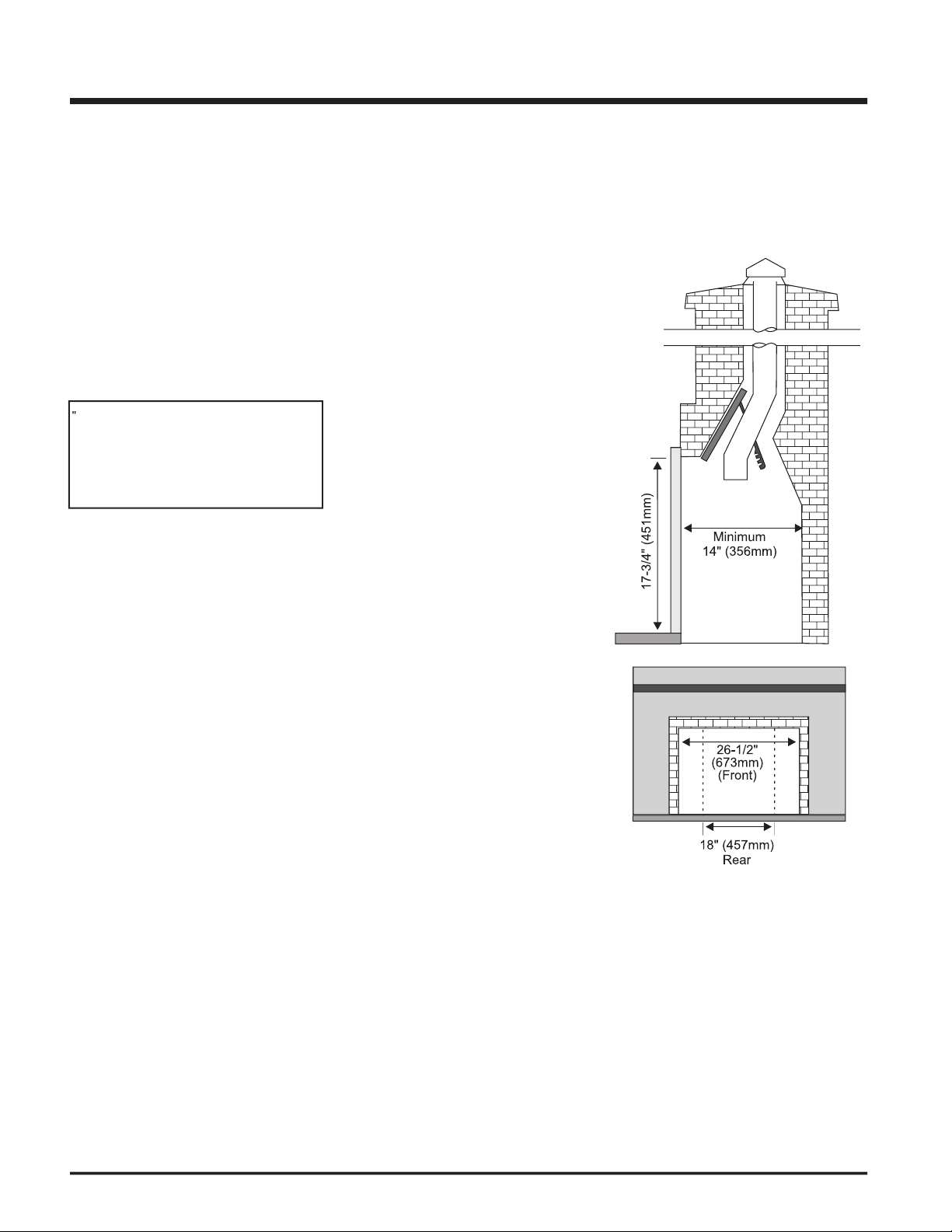
Ensure that the applia nc e i s venting
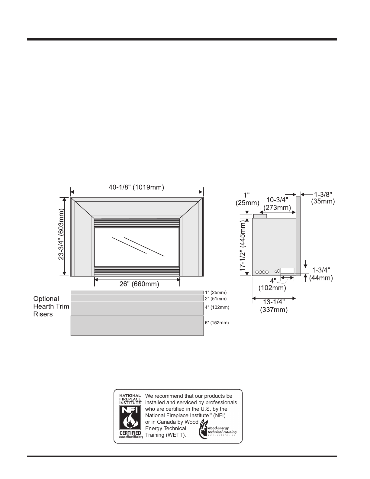
the minimum fireplace dimensions are as
follows:
Width (at front):
29-1/8" (740mm)
15" (381mm)
18-5/8" (473mm)
WARNING
for use with a gas fi replace insert only and
Page 7
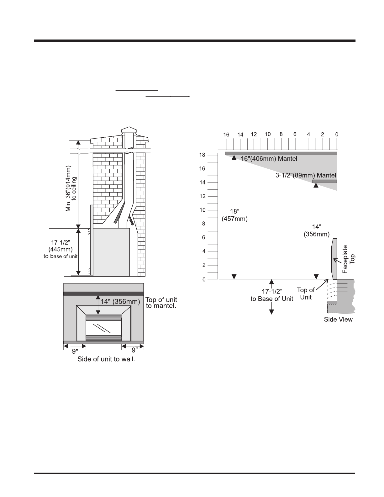
the louver to a combustible mantel is
Page 8
Regency E21 Gas Fireplace Insert
Propane: 0-4500 ft.
Natural Gas Propane
Burner #43 #54
- Natural Gas 23,500 Btu/h
Natural Gas
-Propane +/-5% 11,250 Btu/h
Natural Gas min. 5.0" w.c.
Propane min. 12.0" w.c.
Natural Gas 3.8" +/- 0.2" w.c.
Propane 11" +/- 0.2" w.c.
Variable Speed:
127 CFM, thermally
tude: 2000 ft - 4500 ft.
44 DMS
11,000 Btu/h
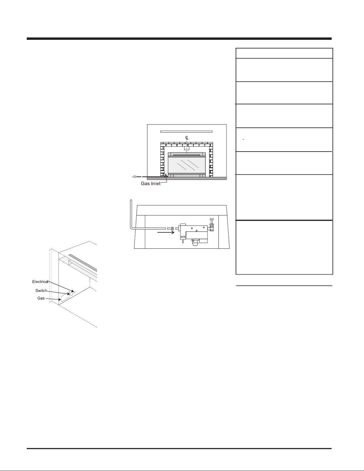
this appliance.
the left side of the unit. The gas line connection
for servicing.) Since some municipalities have
with your local authorities and the CAN/CGA
the current National Fuel Gas Code, ANSI
When using copper or fl ex connectors use only
fl ex connectors are usually considered to meet
this requirement.
with a soap and water solution or gas
for leak testing.
If the appliance is to be installed into an
the masonry fi replace that has been chosen
for the Regency Gas Fireplace.
The appliance is provided with an opening on
the left hand side of the control compartment
for the gas line.
than 1/2 psig are used then this appliance must
testing.
Page 9
fastened in original position.
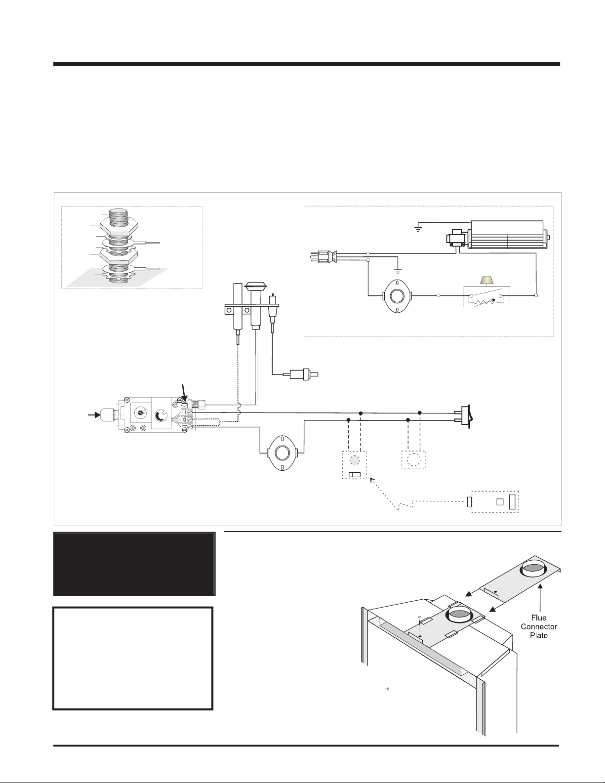
WIRING DIAGRAM FOR THE E21-NG1 AND E21-LP1
WARNING: Electrical Grounding
three pronged (grounding) plug for
your protection against shock hazard
for operation. In case of a power failure, the
thermostat will continue to operate. However,
fan/blower operation.
When connected with 120 volts, the appliance
with local codes or, in the absence of local
with the National Electrical Code ANSI/NFPA
temperature.
Green
Ground
Neutral
Live
Black
Black
Re
d
Black
Fan
Thermodisc
ON OFF
Rotary Speed
Control
120V AC
60 Hz
Ground
Fan
Grounding
Lug Detail
Lockwasher
Fan ground
Power cord
ground wire
St
ar washer
Nut
Nut
#8 Ground Lug
St
ar washer
Gas
Pilot
Thermopile
Electrode
Gas
In
Piezo
Ignitor
Thermocouple
In
Brown
Re
d
White
Pilot
Assembly
"S.I.T" Valve
H
I
L
O
O
F
F
O
N
P
I
L
O
T
Vent Spill
Switch
(Auto Reset)
Burner
ON
OFF
Remote
Transmitter
(Optional)
Thermostat
(Millivolt)
(Optional)
Remote
Receiver
(Optional)
(Millivolt)
ONOFF
Regency
Black
Red
Remove the screw holding the fl ue connector
Slide the plate out and attach to
the fl ue liner inside the fi replace
to the fl ue collar with three sheet
Place the appliance on the hearth.
Replace the screw holding the plate just
the fi replace.
CAUTION: Label all wires prior
to disconnection when servicing
cont r ols . Wi r in g err o rs c an
cause improper and dangerous
operation.
Page 10
Regency E21 Gas Fireplace Insert
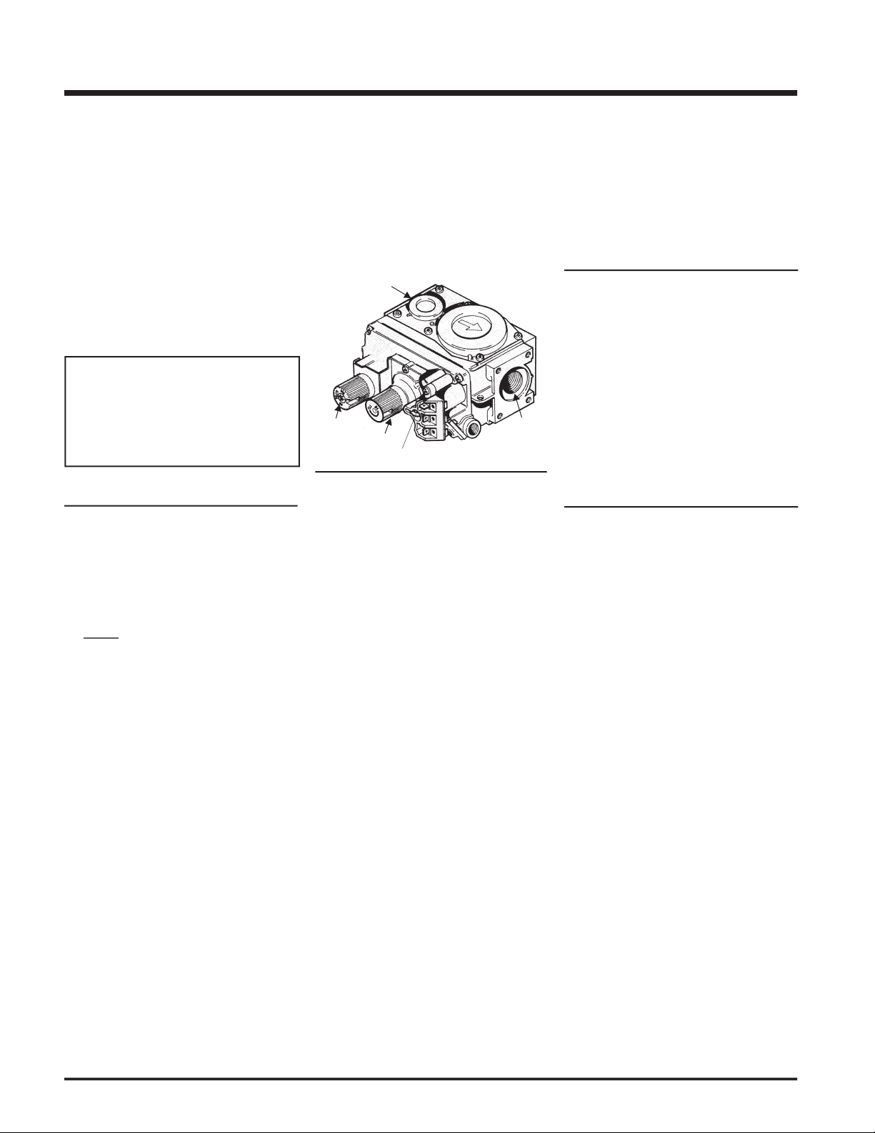
testing of the gas supply piping system at test
Make sure the valve is in the "OFF"
Loosen the "IN" and/or "OUT" pressure
tap(s), turning counterclockwise with a 1/8"
wide fl at screwdriver.
Attach manometer to "IN" and/or "OUT"
Light the pilot and turn the valve to "ON"
The pressure check should be carried out
with the unit burning and the setting should
When fi nished reading manometer, turn
tighten the screw (clockwise) with a 1/8"
fl at screwdriver.
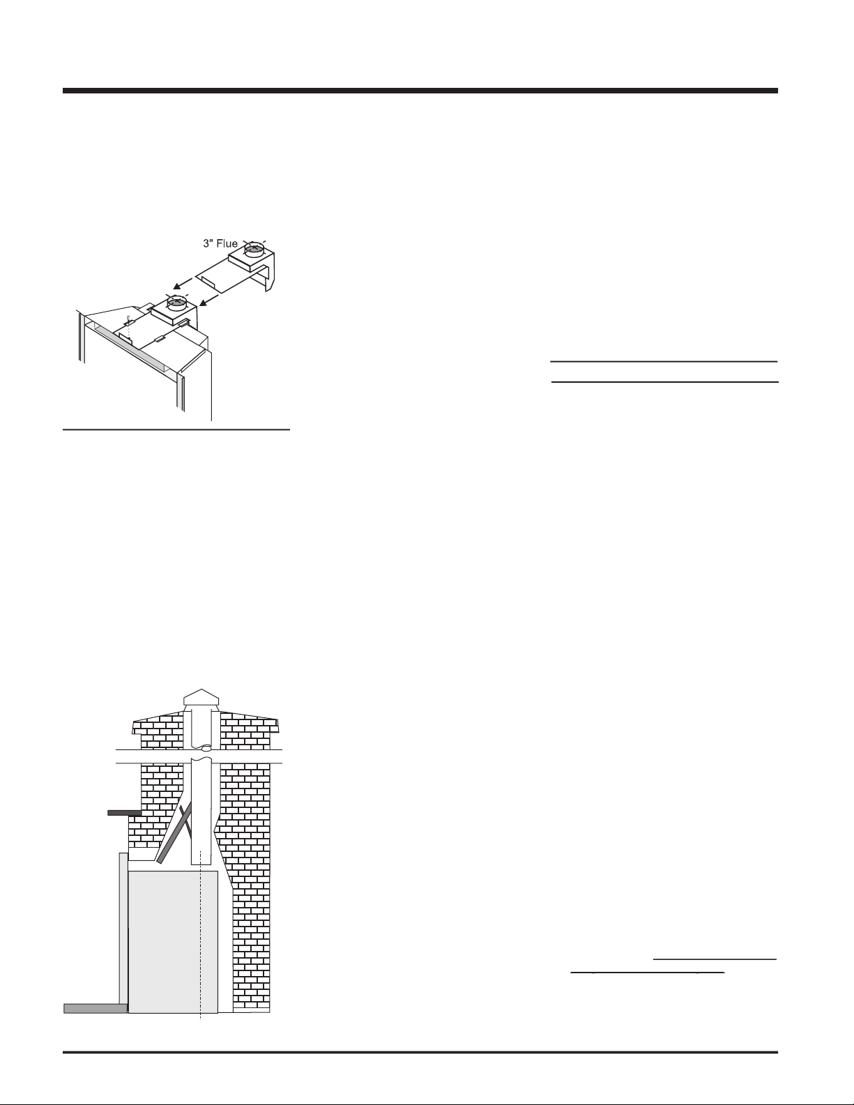
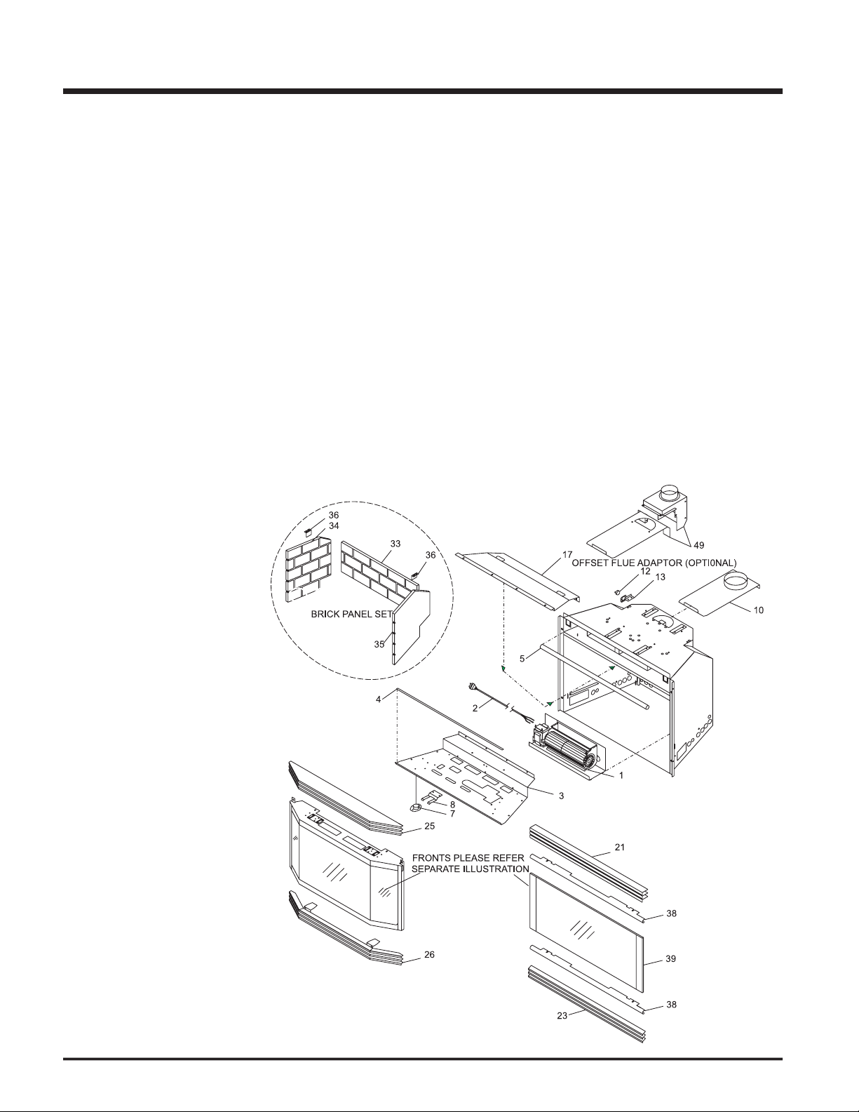
ADAPTOR
A Offset Flue Adaptor Kit,
is
fi replaces.
VENTING
to the vent by sheet metal screw or a B-Vent,
A 3" diameter type B-Vent or approved aluminium
fl ex liner may also be used with a 4" to 3" reduc-
when the unit is in operation.
falling down and crushing the liner.
function without being connected to a proper
WARNING: Operation of this heater
when not connected to a properly
the following venting rules:
Use only certifi ed Type B gas vent or
4)
Use as few elbows as possible.
Keep horizontal lengths as short as possible
Terminate the vent with a suitable certifi ed
vent cap.
VENTILATION AIR
WARNING: This appliance needs fresh air
for safe operation and must be installed
with provisions for adequate combustion
which it is to be operating.
Air for combustion is drawn in through the front
Page 11
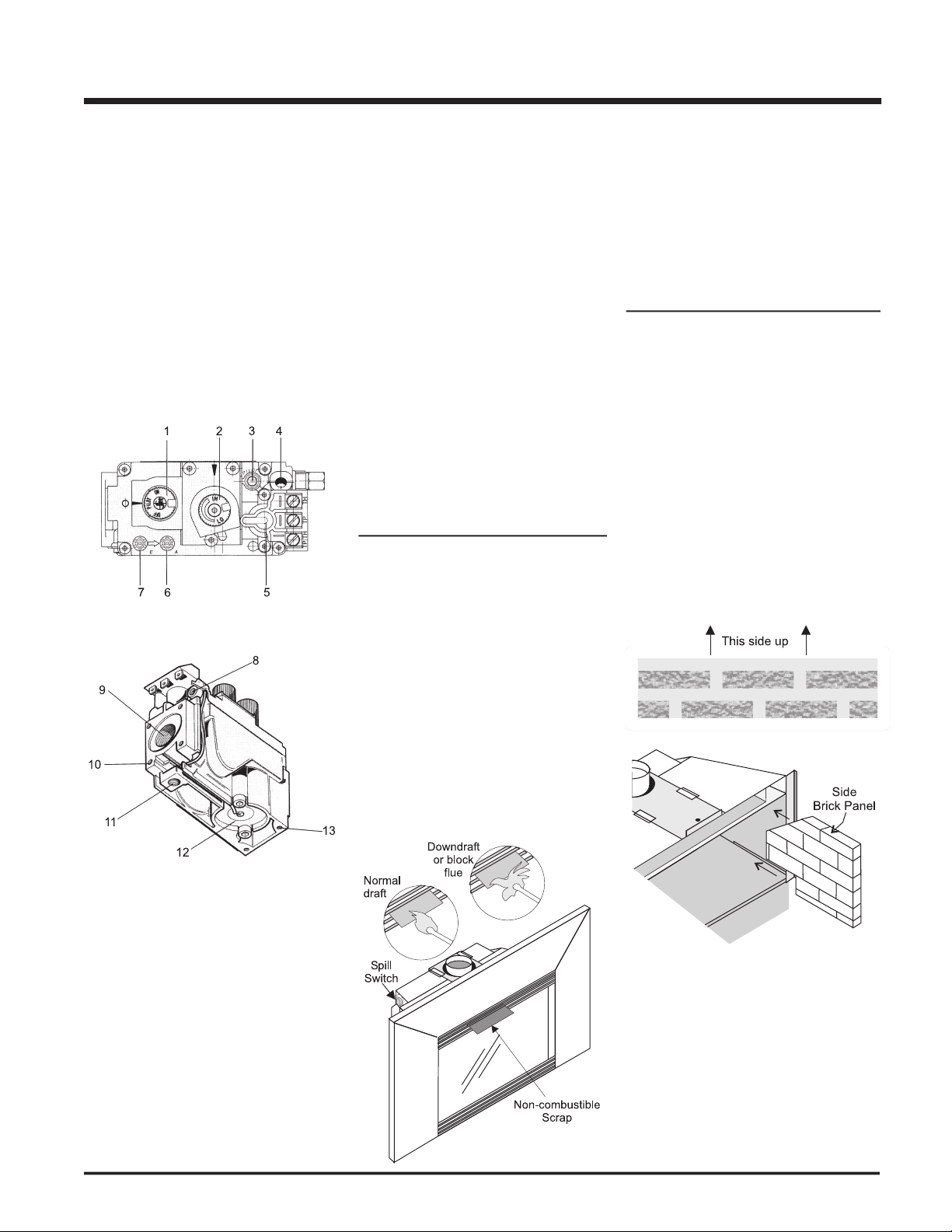
A " spillage" test must be made before
the installed unit is left with the customer.
the house.
Light the unit and set controls to maximum.
After fi ve minutes, test that there is a “pull”
the louver. To ensure a valid test, place
Natural Gas: 1/8" (3.2mm) open
Propane: 3/16" (4.8mm) open
the aeration controls is NOT covered
this will prevent the natural convection of the
Unwrap the brick pattern panels from the
With the glass removed, position the
the side brick panel into place from the front
The brick panels should be tight against
the fi rebox sides and back. The side panels
the brick panel tabs.
Valve Description
Gas cock knob
Manual high/low adjustment
Pilot Adjustment
Thermocouple Connection
Main Operator
Inlet Pressure Tap (Supply Pressure)
Pilot Outlet
Main Gas Outlet
Flange Securing Screw Holes
Alternative TC Connection Point
Thermoelectric Unit
Additional Valve Mounting Hole
Page 12

Regency E21 Gas Fireplace Insert
Place the embers on the front lip of the
Place pieces of rockwool on the front lip of
the burner as shown below.
Place the Front Left Log B) 02-67 on the 2
front pins.
Lay the faceplate panels fl at, face down on
Take the top faceplate and align the holes
the screws provided, attach from the top of
the panel (the holes in the top panel are
Hint:
Don't tighten the trim to
E)02-69
Position the Middle Left Log C) 02-68 onto
the 2 pins as shown below. The left edge
Place the Front Right Log E) 02-69 onto the
front right pin and the cutout on the bottom
the following:
02-66 Rear Log
02-67 Front Left Log
02-70 Middle Right Log
02-69 Front Right Log
f)
Embers
Vermiculite
Rockwool
Carefully remove the logs from the box and
with care -
Sprinkle the vermiculite around the fi rebox
Pla c e th e
A) 0 2 - 66
A)02-66
Place the Middle Right Log D) 02-70 into the
front of Log D)02-70 snugly between Logs
Page 13

Connect the ON/OFF switch wires by taking
the black and red wires with the female
Install the
onto the glass
Slide the glass into the bottom glass trim
Slide the top glass trim by sliding under the
two spring clips.
WARNING
The power cord should be run behind the
faceplate panel.
Attach the brass trim to the faceplate by
the trim to the faceplate panels using the
Using the connectors provided, join the left
top trim. See diagram 2. Connect the right
Place the trim on the assembled faceplate
the switches with the notch on the left side
Connect the fan switch wires by taking the
the grey harness) and connect them with
the wire connectors from the fan speed
Tuck the wires into the faceplate to keep
them away from the insert using the clip
faceplate to ensure that the wires do not
touch the side of the unit. See diagram 3.
Attach the faceplate panels to the insert
Push the logo plate into the two holes in
the bottom left corner of the faceplate. See
Page 14

Regency E21 Gas Fireplace Insert
Install top louver by sliding the two bracket
IMPORTANT
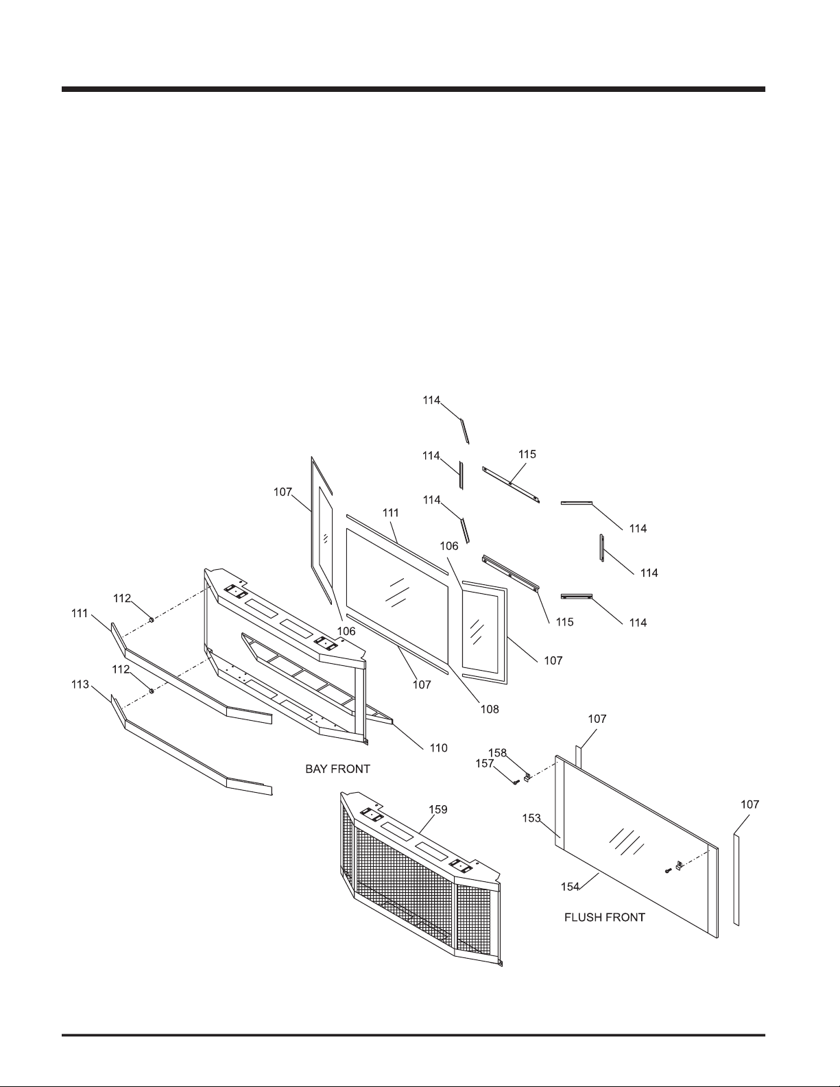
Place the bay door onto the 2 pins on the
top of the unit.
Position 2 magnets on the back of each trim
Install top and bottom louvers.
Install bottom louver by sliding the two
the Bay Front as per diagram 1.
The Top Louver is held in place by Spring
Install the Spring Hinges on the left and right
Place the Bottom Louver near the hinge. Flip
Flush glass must stay in place
when bay option is used. The bay
front is a decorative overlay only.
Page 15

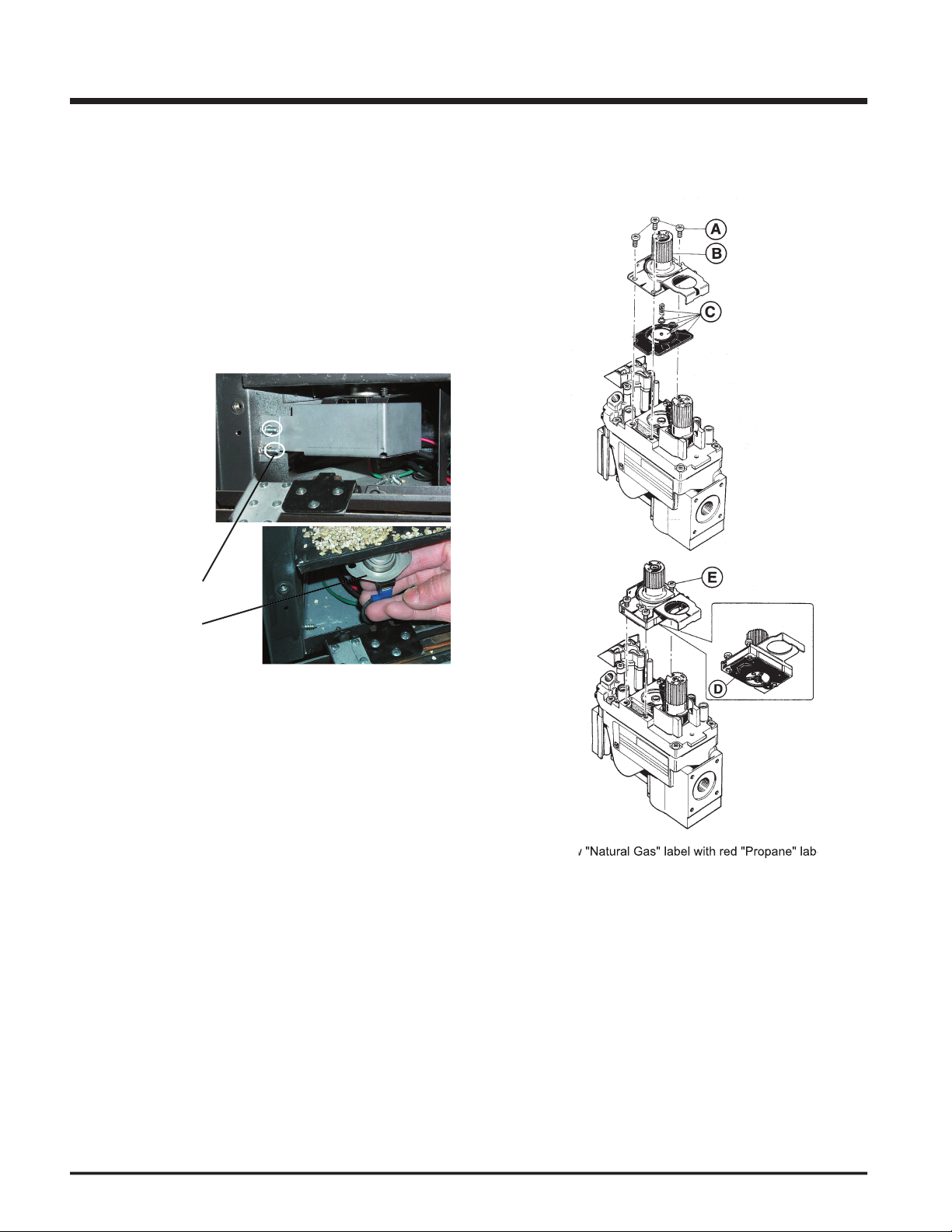
THIS CONVERSION MUST BE DONE BY A QUALIFIED GAS FITTER
Turn the unit off and allow it to cool to room temperature.
Unplug or disconnect power source to stove.
Remove glass front (see manual).
Remove logs and brick panels (if installed).
Remove the Grate by removing the screws on each side of the
Remove the Burner Tray by removing 1 screw on each side of the
tray, then slide the tray to the left and lift out.
Pull off the pilot cap to expose the pilot orifi ce.
Unscrew the pilot orifi ce with the allen key (provided) and replace
with the LP pilot orifi ce in the kit.
Remove burner orifi ce with 1/2" wrench. Use another wrench to hold
push Burner Tray to the left, and lift off.
IF IN DOUBT DO NOT DO THIS CONVERSION !!
Page 16
Regency E21 Gas Fireplace Insert
Attach clear label "This unit has been converted to Propane" near or
from NG to LPG using SIT conversion Kit Code 0.907.202" onto the
valve.
Check for gas leaks.
Check inlet and outlet pressures.
Check operation of fl ame control.
Check for proper fl ame appearance and glow on logs.
Remove and discard the 3 pressure regulator mounting screws (A),
Insure that the rubber gasket (D) is properly positioned and install
the new HI/LO pressure regulator assembly to the valve using the
Replace Burner Tray and reverse steps 6) to 1).
Adjust the burner aeration setting from 1/8" to 3/16" as required for
the best fl ame picture.
Remove the switch cover from the left side of the body base and pull
the thermodisc out of the bracket under the left side of the fi rebox
Page 17

Hold the full screen door up against the unit in order to make the
following wire connections.
Pull the ON/OFF connector wires thru the box and connect them to
the switch.
Connect the fan switch wires with the wire connectors from the fan
Lift the unit up slightly and push down on the corners of the Bottom
Completely secure full screen door to the unit by securing 4 screws
to the Left and Right Side Trim.
Page 18
Regency E21 Gas Fireplace Insert
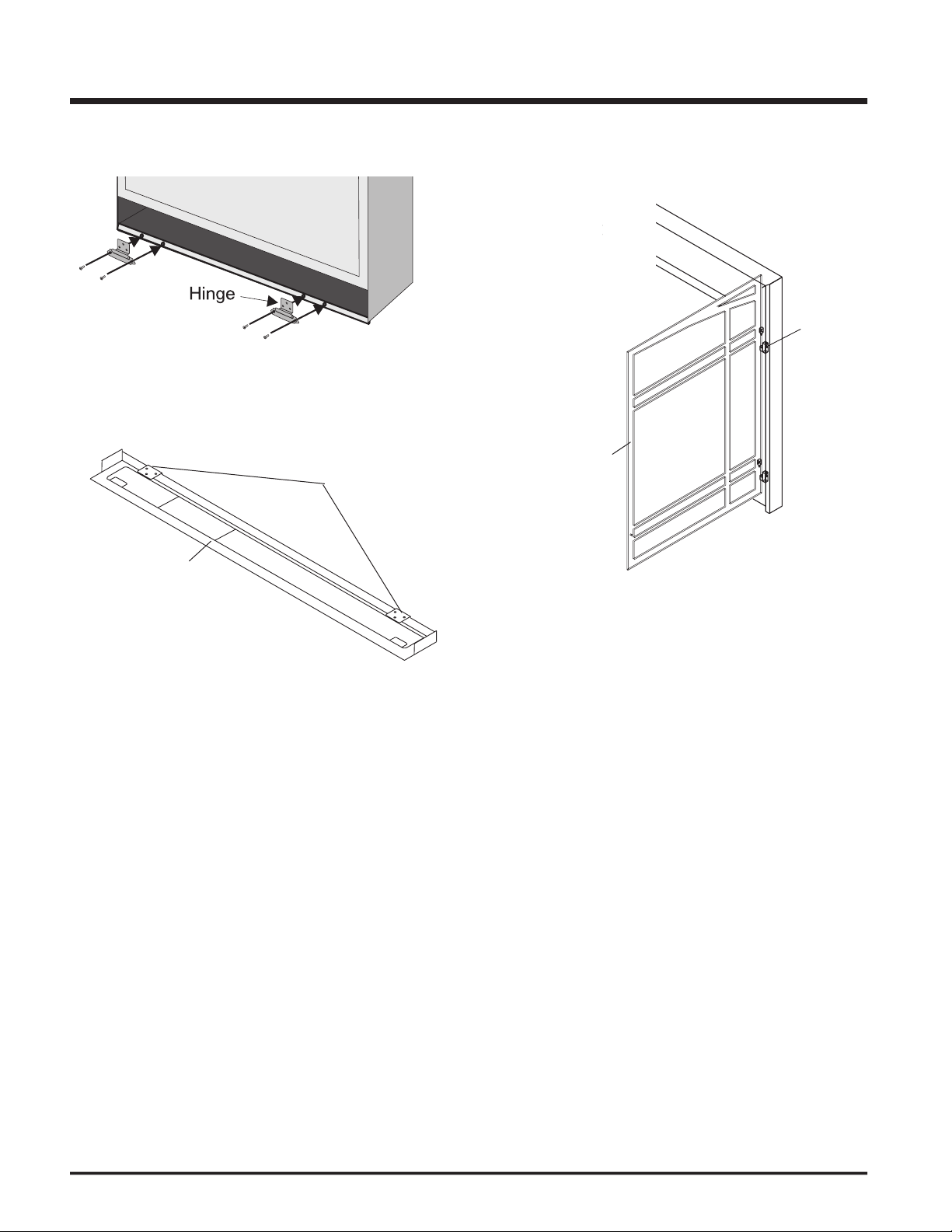
Place Bottom Frame near hinge. Flip hinge over Bottom Frame and
Install Spring Hinges to the Left and Right Side of the bottom of the
fi rebox using 2 screws per hinge.
Install the Left and Right Side Screen Doors by placing over top of
the hinges on the faceplate.
Hold the door at a 45 degree angle to avoid scratching the
faceplate.
Close screen doors.
Page 19

wall thermostat wires
WALL SWITCH
Run the wire through the right or left side
wire.
Connect the wire to the supplied wall switch
wall switch wire
1:
for this unit. Use of other systems may void
your warranty.
transmitter, a receiver and a wall mounting
Choose a convenient location on the wall
to install the receiver and the receptacle
that location. Use Thermostat Wire Table.
Connect the two wires to the gas valve. See
to 120V wire.
Install 3 AAA alkaline batteries in transmitter
3:
WALL THERMOSTAT
A wall thermostat may be installed if desired,
wire length.
thermostat but any 250-750 millivolt rated non-
H
I
L
O
O
F
F
O
N
P
I
L
O
T
TP
TH
To
wall
switch,
remote
control
or
thermost
at
To
thermopile
THTP
Wire Size Max. Length
Page 20
Regency E21 Gas Fireplace Insert
Clocking the appliance to ensure the
If required, adjusting the primary air to ensure
that the fl ame does not carbon. First allow
the unit to burn for 15 min. to stabilize.
Check for proper draft.
Turn gas control knob counter clockwise to
Use the rocker switch to operate main
Rotate the variable fl ame control to adjust
the fl ame height higher or lower.
Close the bottom louver assembly.
Use the rocker switch to turn off the main
Push in the gas control knob slightly and
turn clockwise to "OFF". Do not force.
to the appliance if service is to be
fi rst time you use it with the fan on. When fi rst
WITHOUT THE GLASS FRONT IN
the following check list.
operating this appliance.
Check to see that all wiring is correct and
turned from "PILOT" to "OFF" unless it is
Open the bottom louver assembly
If the control knob is in the "OFF" position
from "PILOT" to "OFF" unless knob is
Wait fi ve minutes to allow gas, that may
this manual. If you don't smell gas continue
Turn the gas control counter clockwise to
Push in control knob all the way and hold
the gas control knob. The pilot fl ame should
Verify log placement. If the pilot cannot be
The unit should never be turned off and on
wait.
When lighting the appliance, the inside of
the glass may fog up, this will burn off after
Make sure the glass door is in place.
Verify that all venting and the cap is
Gas In
Shut Of
f
Hi-Low
Pilot Adjust
Gas Out
TPTH
TP
TH
Any alteration to the product that causes
Page 21

A)
This
which
When
the
these
smell
the
some
than
will
settle
the
WHAT
TO
YOU
try
to
touch
use
your
building.
your
the
supplier’s
you
your
the
your
to
turn
the
use
tools.
the
will
turn
by
try
to
Technician.
use
this
been
water.
technician
to
the
to
the
which
been
under
water.
This
there
ventilation
while
touch.
to
temperatures
vapors
the
this
turn
to
turned
to
Wait
to
you
then
the
this
you
to
the
Turn
to“PILOT”
the
way
the
to
the
the
will
to
when
your
technician
the
will
tries,
turn
the
to
your
technician
Turn
to
to
YOUR
This
be
with
the
ANSI
Z223.1/NFPA
Australia:
AG601,
Zealand:
WARNING:
you
these
tions
to
the
with
this
tional
TO
TURN
APPLIANCE
THIS
the
turn
to
Turn
to
the
to
Page 22

Regency E21 Gas Fireplace Insert
Always turn the gas valve to off before
vacuuming at least once a year.
When cleaning the logs, use a clean soft
Clean (never when unit is hot) appliance,
The heater is fi nished in a heat resistant
Make a periodic check of burner for proper
fl ame of the burner periodically, making sure
the fl ames are steady; not lifting or fl oating.
4)
The appliance and venting system must be
that the fl ow of combustion and ventilation
During the annual service call, the burners
Keep the area near the appliance clear and
free from combustible materials, gasoline
the glass properly secured in place
Verify proper operation after servicing.
Periodically check the pilot fl ames, see
the diagrams on page 11. If you have
the unit’s performance which is not
ACCESSORIES
AUTOMATIC
the side of the faceplate to adjust to the desired
APPLIANCES
from your gas appliance. This is perfectly normal
to push heated air farther into the room. It is not
when ON. This sound will increase or decrease
your fan speed control.
will expand and contract at slightly different
for steel fi reboxes.
When this thermally activated switch turns ON
While the pilot fl ame is on it can make a very
As the gas control valve turns ON and OFF, a
WARNING: CHILDREN AND ADULTS
APPLIANCE MUST BE REPLACED PRIOR
Page 23

ASSEMBLY
Shut off the gas.
Remove top and bottom louvers.
4)
Remove top and bottom trim.
Remove glass.
Remove log set & embers, and brick
Disconnect the gas line.
Remove wires from valve (top and bottom
terminals).
Remove the burner tray by removing the 1
the left and lift out.
IMPORTANT
Shut off the gas.
Remove top and bottom louvers.
Remove top and bottom trim.
Remove glass.
Remove logs, embers, and brick panels.
Remove Burner Tray and Firebox bottom
Assembly.
Remove wires from fan.
Lift fan off of the two pins.
Reverse steps to install fan.
Remove the switch cover from the left side
fi rebox bottom.
Remove valve assembly from stove body
Remove the valve from the bracket and
Your Regency stove is supplied with high
temperature, 5 mm Neoceram ceramic glass that
will withstand the highest heat that your unit will
Remove the nuts holding the glass retainers
Remove the glass retainers (sides, top and
Replace the glass.
Reverse the previous steps, replace the
Replace door on the stove and check the
Remove the 2 screws on each side of the
fi rebox bottom and 4 screws on the rear
wall., and lift out.
Disconnect power supply
before servicing
Page 24
Regency E21 Gas Fireplace Insert
Part # Description Part # Description
530-518/P Fan Assembly
910-752 Wire Harness (Intermediate)
4) 936-238 Soft Fiber Gasket 8mm
910-233 Fan AUTO ON/OFF Thermodisc - LP
532-910 Flush Louver (set)-Black
532-912 Flush Louver (set)-Gold/Black
532-914 Flush Louver (set)-Steel/Black
530-952 Bay Louver (set)-Black
530-954 Bay Louver (set)-Gold/Black
530-955 Bay Louver (set)-Steel/Black
530-945 Brick Panel Set - Standard
532-901 Brick Panel Set - Standard Brown
532-902 Brick Panel Set - Standard Red
532-903 Brick Panel Set - Herringbone Brown
532-904 Brick Panel Set - Herringbone Red
49) 532-920 Offset Flue Adaptor Kit
530-936 Zero Clearance Kit
918-354 E21 Manual
Page 25

Part # Description
533-574/P Valve Assembly- Nat. Gas
533-576/P Valve Assembly - Propane
910-099 Valve SIT - Propane
910-077 Pilot Assembly - SIT - 3 fl ame - Propane
904-162 #43 Orifi ce (NG)
904-163 #54 Orifi ce (LP)
533-969 Conversion to Propane Kit
Page 26
Regency E21 Gas Fireplace Insert
Part # Description Part # Description
530-950 Complete Bay Front c/w Black Trim
402-905 Bay Brick Panel - Standard Brown
402-906 Bay BricK Panel - Standard Red
402-956 Gold Trim Bay Front
402-958 Steel Trim Bay Front
530-547/P Flush Door Assembly Complete
Page 27
Part # Description
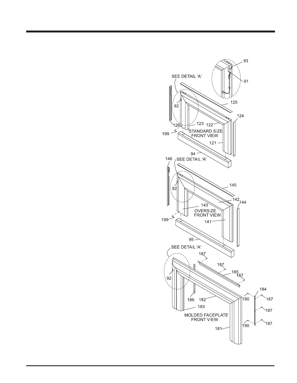
400-950 Hearth Trim 1" Standard
320-940 Hearth Trim 1" Oversize
400-926 Hearth Trim 2" Standard
320-942 Hearth Trim 2" Oversize
400-959 Hearth Trim 6" Standard
320-946 Hearth Trim 6" Oversize
532-918 Faceplate & Trim (Set) - Standard-Contour - Black
532-950 Trim (Set) - Standard - Contour (Brass)
532-919 Faceplate & Trim (Set) - Oversize-Contour - Black
531-933 Molded Faceplate & Trim (Set)
402-918 Faceplate & Trim (Set) - Zero Clearance Kit-Contour
Page 28

Regency E21 Gas Fireplace Insert
___________________________________________________
___________________________________________________
___________________________________________________
___________________________________________________
___________________________________________________
___________________________________________________
___________________________________________________
___________________________________________________
___________________________________________________
___________________________________________________
___________________________________________________
___________________________________________________
___________________________________________________
___________________________________________________
___________________________________________________
___________________________________________________
___________________________________________________
___________________________________________________
___________________________________________________
___________________________________________________
___________________________________________________
___________________________________________________
___________________________________________________
___________________________________________________
Page 29

___________________________________________________
___________________________________________________
___________________________________________________
___________________________________________________
___________________________________________________
___________________________________________________
___________________________________________________
___________________________________________________
___________________________________________________
___________________________________________________
___________________________________________________
___________________________________________________
___________________________________________________
___________________________________________________
___________________________________________________
___________________________________________________
___________________________________________________
___________________________________________________
___________________________________________________
___________________________________________________
___________________________________________________
___________________________________________________
___________________________________________________
___________________________________________________
Page 30

Regency E21 Gas Fireplace Insert
___________________________________________________
___________________________________________________
___________________________________________________
___________________________________________________
___________________________________________________
___________________________________________________
___________________________________________________
___________________________________________________
___________________________________________________
___________________________________________________
___________________________________________________
___________________________________________________
___________________________________________________
___________________________________________________
___________________________________________________
___________________________________________________
___________________________________________________
___________________________________________________
___________________________________________________
___________________________________________________
___________________________________________________
___________________________________________________
___________________________________________________
___________________________________________________
Page 31

thoroughly before it leaves our facility. FPI Fireplace Products International Ltd. is pleased to extend this limited lifetime warranty to the
of a
The Warranty:
Warranty for fi ve (5) years for parts and subsidized labour* and parts only thereafter.
Any part or parts of this unit which in our judgement show evidence of such defects will be repaired or replaced at FPI's option, through an accredited distributor or agent provided
that the defective part be returned to the distributor or agent
Transportation Prepaid,
Transportation Prepaid,
if requested.
for manufacturer defect.
At all times FPI reserves the right to inspect product in the fi eld which is claimed to be defective.
All claims must be submitted to FPI by authorized selling dealers. It is essential that all submitted claims provide all of the necessary information including customer name,
At no time will FPI be liable for any consequential damages which exceed the purchase price of the unit. FPI has no obligation to enhance or modify any unit once manufactured.
Any unit which shows signs of neglect or misuse is not covered under the terms of this warranty policy.
warranty on this product.
Any alteration to the unit which causes sooting or carboning that results in damage to the interior / exterior facia is not the responsibility of FPI.
Page 32

______________________________________________
___________________________________________________________________
___________________________________________________________
___________________________________________________________
______________________________________________________
__________________________________________________________
with reliability and simplicity in mind. In
Fireplace Products International
Fireplace Products International
Fireplace Products International
Fireplace Products International
Fireplace Products International
Regency and energy are trademarks of FPI Fireplace Products International Ltd.
© Copyright 2005, FPI Fireplace Products International Ltd. All rights reserved.
 Loading...