

Page 1
E18 Gas Insert
www.regency-fi re.com
Owners &
Installation Manual
www.regency-fi re.com
MODELS: E18-NG Natural Gas E18-LP Propane
WARNING:
If the information in these instructions are not followed exactly,
a fi re or explosion may result causing property damage,
personal injury or loss of life.
FOR YOUR SAFETY
Do not store or use gasoline or other fl ammable vapors and
liquids in the vicinity of this or any other appliance.
Installation and service must be performed by a qualifi ed
installer, service agency or the gas supplier.
Tested by:
Installer: Please complete the details on the back cover
and leave this manual with the homeowner.
Homeowner: Please keep these instructions for future reference.
919-180d
FPI FIREPLACE PRODUCTS INTERNATIONAL LTD. 6988 Venture St., Delta, BC Canada, V4G 1H4
FOR YOUR SAFETY
What to do if you smell gas:
Do not try to light any appliance
Do not touch any electrical switch:
do not use any phone in your
building.
Immediately call your gas supplier
from a neighbour's phone. Follow
the gas supplier's instructions.
If you cannot reach your gas
supplier, call the fi re department.
12/02/13
Page 2
CONGRATULATIONS!
You are the owner of a state-of-the-art Gas Insert by:
FPI FIREPLACE PRODUCTS INTERNATIONAL LTD.
The Regency® Gas Fireplace Series has been designed to provide you with all the warmth and
charm of a fi replace, at the fl ick of a switch. The models E18-NG and E18-LP of this series have been
approved by Warnock Hersey for safety. As it also bears our own mark, it promises to provide you with
economy, comfort and security for many trouble free years to follow. Please take a moment now to
acquaint yourself with these instructions and the many features of your Regency® Fireplace.
2
Regency® E18 Gas Fireplace Insert
Page 3
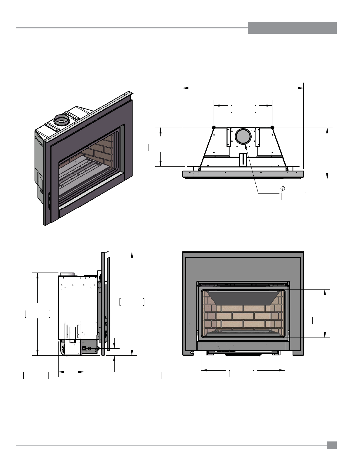
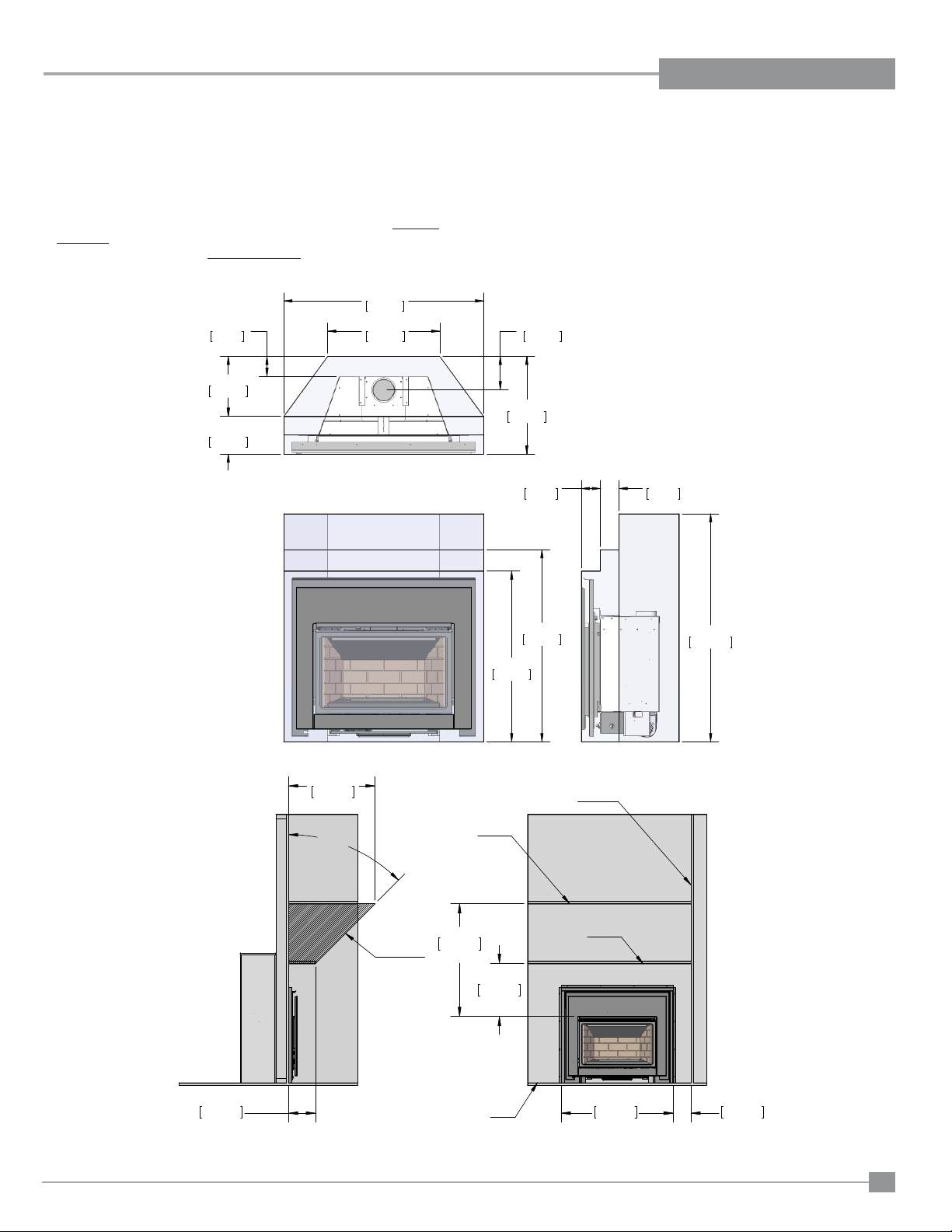
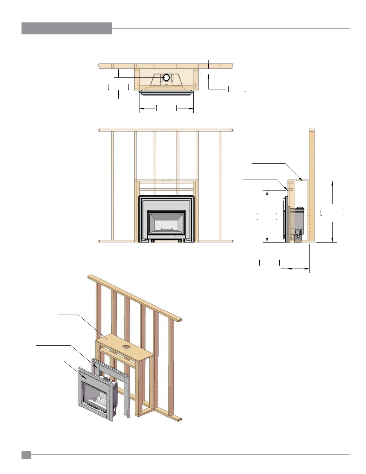
UNIT DIMENSIONS
P
PP
PP
PP
DIMENSIONS
PP
P
PP
PP
PP
PP
PP
PP
Regency® E18 Gas Fireplace Insert
Diagram 1.1
3
Page 4

TABLE OF CONTENTS
DIMENSIONS
Unit dimensions .................................................................. 3
INSTALLATION
Before You Start .................................................................. 7
Important Message ........................................................... 7
Save these instructions ...................................................... 7
General Safety Information ................................................. 7
Installation Checklist ........................................................... 8
High Elevation ..................................................................... 8
Air Shutter Adjustment ........................................................ 8
Gas Pipe Pressure Testing ................................................. 9
Gas Connection .................................................................. 9
Installation Checklist ......................................................... 10
Materials required ............................................................. 10
Minimum Fireplace Opening for ....................................... 10
Masonry and factory built fi replaces ................................. 10
Venting .............................................................................. 10
Minimum Fireplace Clearances ........................................ 11
Zero Clearance framing .................................................... 12
Venting Confi gurations ..................................................... 12
EP28-4/EP28-5 Installation Specifi cations ....................... 19
ZERO CLEARANCE KIT INSTALLATION
ZC kit installation ............................................................... 13
STEPS REQUIRED TO PREPARE THE E18 FOR
INSTALLATION
Required steps and procedure for the E18 install ..............17
Tools required .....................................................................17
Separating the Outer Firebox Shell from the Inner Firebox
18
Step #4: Surround Installation ....................................... 40
Remote control Installation ............................................41
Conversion from NG to LP.............................................41
Glass Burner Installation ...............................................44
Enamel panel Installation ..............................................45
Glass crystal and stone install .......................................46
Optional Spa or volcanic stones Installation ................. 46
Brick panel Installation ...................................................47
Log Tray Installation ......................................................48
Log Set Installation ........................................................48
Optional Log Set Installation ..........................................50
Glass Door Installation ..................................................52
Safety Screen Replacement .......................................... 52
Drafthood check ............................................................53
Remote Control .............................................................53
Wall Switch ....................................................................53
Wall Thermostat ............................................................ 53
Safety Switches .............................................................54
Operation Controls ........................................................54
Fireplace Controls .........................................................54
Final Check ....................................................................55
Operating Instructions ..................................................55
Lighting Procedure ........................................................55
Shutdown Procedure .....................................................55
Pilot Adjustment .............................................................56
Copy of Lighting Plate Instructions ...............................56
First Fire ........................................................................56
Operation ....................................................................... 56
Normal Operating Sounds of Gas Appliances ............... 57
Maintenance Instructions .............................................. 57
Log Replacement ..........................................................57
Glass Gasket .................................................................57
Valve replacement ......................................................... 58
Installing Valve ...............................................................58
Removing the Fan ......................................................... 59
Wiring Diagrams ............................................................60
PARTS LIST
INSTALLING THE E18 INTO THE EXISTING ZC
BOX
Modifi cation of Montigo EP28-S2 ......................................21
Modifi cation of Montigo 28F-2 or 28-F ...............................23
28 F / 28 F2 Installation Specifi cations ..............................26
Modifi cation of Montigo 36SR ............................................27
Modifi cation of Firesong 220N ...........................................31
Modifi cation of Firesong 120N ...........................................33
INST ALLATION AND OPERATION
Installation of the E18 into Existing Units .......................... 38
Step #1: Vent Connection Type A ...................................... 38
Step #1: Vent Connection Type B ...................................... 38
Step #2: Outer Shell Installation ........................................ 39
Step #3: Firebox Installation .............................................. 39
4
Main Assembly ..............................................................61
Montigo EP28 Installation Kit .........................................62
Montigo 28-F and 28F-2 Installation Kit .........................63
Montigo 36SR Installation Kit ........................................65
Firesong 220N Installation Kit ........................................65
Firesong 120N Installation Kit ........................................66
WARRANTY
Warranty ........................................................................67
Regency® E18 Gas Fireplace Insert
Page 5
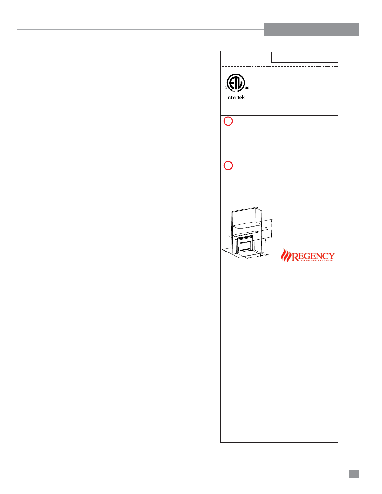
This is a copy of the label that accompanies each Regency® Gas Insert. We have
printed a copy of the contents here for your review. The safety label is located on the
front inside base of the unit visible when the bottom louver is open.
®
Note: Regency
units are constantly being improved. Check the label on the
unit and if there is a difference, the label on the unit is the correct one.
Please note that with the addition of thermostat control and outside
combustion air supply, this unit is approved for bedroom installations.
For the State of Massachusetts, installation and repair must be done by a plumber
or gasfi tter licensed in the Commonwealth of Massachusetts.
For the State of Massachusetts, fl exible connectors shall not exceed 36 inches
in length.
For the State of Massachusetts, the appliances individual manual shut-off must
be a t-handle type valve.
The State of Massachusetts requires the installation of a carbon monoxide alarm
in accordance with NFPA 720 and a CO alarm with battery back up in the same
room where the gas appliance is installed.
SAFETY LABEL
415
DO NOT REMOVE THIS LABEL / NE PAS ENLEVER CETTE ETIQUETTE
Listed:
VENTED GAS FIREPLACE HEATER
/ FOYER AU GAZ À ÉVACUATION
4001172
Model: E18-NG
Model: E18-LP
F
Certified for/Certifi e pour:
Tested to:
Conforms to: ANSI Z21.88a-2012
Certified to: CSA 2.33a-2012
NATURAL GAS FIREPLACE INSERT: MODEL E18-NG
Factory Equipped For Altitude 0-4500ft. (0- m)1370
Min. supply pressure 5" WC (1.25kPa)
Low Setting Man. pressure 1.6" WC (0.40kPa)
Max. Manifold pressure 3.5" WC (0.87kPa)
Orifice size 44 DMS (2.64mm)
Minimum input 15,000 Btu/h (4.40kW)
Altitude 0-4500ft (0-610m)
Maximum input 21,600 Btu/h (6.33kW)
PROPANE FIREPLACE INSERT: MODEL E18-LP
Factory Equipped For Altitude 0-4500ft. (0-1370m)
Min. supply pressure
Low Setting Man. pressure
Max. Manifold pressure
Orifice size
Minimum input
Altitude
Maximum input
A
Duplicate Serial number
415
Serial No. / No de serie
é
CAN/CGA-2.17-M91(R2009)
12" WC (2.99 kPa)
6.4" WC (1.59 kPa)
10" WC (2.49 kPa)
55 DMS (1.6mm)
17,000 Btu/h (4.98kW)
0-4500ft (0-610m)
20,500 Btu/h (6.01kW)
Minimum Clearances to Combustibles:
Degagement Minimum Des Materiaux
Combustibles:
Min. Mantel Height A 17-7/8"(453mm)
B
Min. Ceiling B 37-7/8"(961mm)
Side wall E 6" (152mm)
Max. Mantel Depth F 9" (229mm)
CANADA and U.S.A.
Height
D
37-1/2"(953mm)
E
D
This appliance must be installed in accordance with local codes, if any; if none,
follow the National Fuel Gas Code, ANSI Z223.1, or Natural Gas and Propane
Installation Code, CSA B149.1.
This appliancemust be installed in accordancewith the Standard CAN/CSA Z240
MH, Mobile Housing, in Canada, or with the Manufactured Home Construction
and SafetyStandard, Title24 CFR,Part 3280, inthe UnitedStates, orwhen sucha
standard is not applicable, ANSI/NCSBCS A225.1/NFPA 501A, Manufactured
Home Installations Standard or ANSI A119.2 ou NFPA 501C Standard for
Recreational Vehicles
This applianceis onlyfor use with thetype of gas indicated on the ratingplate and
may be installed in an aftermarket, permanently located, manufactured (mobile)
home wherenot prohibitedby local codes.See owner'smanual for details.
WARNING. This fireplace has been converted for use with a gas fireplace insert
only and cannot be used for burning wood or solid fuels unless all original parts
have been replaced, and the fireplace re-approved by the authority having
jurisdiction.
Installer l'appareil selonles codes ou règlements locaux,ou, en l'absencede tels
règlements, selon les codes d'installationANSI Z223.1, National Fuel Gas Code
ou CSA-B149.1en vigueur.
Installer l'appareil selonla norme CAN/CSA-Z240, Série MM,Maison mobiles ou
CAN/CSA-Z240 VC, Véhicules de camping, ou la norme 24 CFR Part 3280,
Manufactured Home Construction and Safety Standard. Si ces normes ne sont
pas pertinentes, utilisez la norme ANSI/NCSBCS A225.1/NFPA 501A,
Manufactured Home Installations Standard, ou ANSI A119.2 ou NFPA 501C
Standard forRecreational Vehicles.
Cet appareil doit être utilizeuniquement avec le typede gaz indiqué surla plaque
signalétique. Cet appareil peut être installé dans une maison préfabriquée ou
mobile (É.-U. seulement) installée à demeure si les règlements locaux le
permettent. Voir la notice de l'utilisateur pour plus de renseignements. Cet
appareil ne peut pas être utilisé avec d'autres gaz sauf si une trousse de
conversion certifiéeest fournie.
AVERTISSEMENT: Ce foyer a été converti pour utilisation avecun foyer au gaz
encastrable et ne peut être utiliser pour brûler du bois ou d'autres combustibles
solides à moins que toutes les pièces d'origine aient été remplacées et que le
foyer aitété approuvéde nouveau parl'autorité compétente.
This ventedgas fireplaceheater is notfor usewith air filters.
Ne pasutiliser defiltre à airavec cefoyer au gazà évacuation.
For usewith glassdoors certified withthe applianceonly
Pour utilisationuniquement avecles portes enverre certifiéesavec l'appareil
VENTED GAS FIREPLACE HEATER - NOT FOR USE WITH
SOLID FUELS. / NE PAS
UTILISER AVEC DUCOMBUSTIBLE SOLIDE.
Electrical supply / Électrique 115VAC, 2.5 A, 60Hz,
Less than 10A Fan Part # 911-071
FPI Fireplace Products International Ltd.Delta BC, CANADA
FOYER AU GAZ À ÉVACUATION -
MADE IN CANADA / FABRIQUE AU CANADA
919-179a
Regency® E18 Gas Fireplace Insert
5
Page 6

REQUIREMENTS
5.08: Modifications to NFPA-54, Chapter 10
(2) Revise 10.8.3 by adding the following additional requirements:
(a) For all side wall horizontally vented gas fueled equipment installed in every dwelling, building or structure used in whole or in part for
residential purposes, including those owned or operated by the Commonwealth and where the side wall exhaust vent termination is less than
seven (7) feet above finished grade in the area of the venting, including but not limited to decks and porches, the following requirements shall
be satisfied:
1. INSTALLATION OF CARBON MONOXIDE DETECTORS. At the time of installation of the side wall horizontal vented gas fueled
equipment, the installing plumber or gasfitter shall observe that a hard wired carbon monoxide detector with an alarm and battery back-up is
installed on the floor level where the gas equipment is to be installed. In addition, the installing plumber or gasfitter shall observe that a battery
operated or hard wired carbon monoxide detector with an alarm is installed on each additional level of the dwelling, building or structure
served by the side wall horizontal vented gas fueled equipment. It shall be the responsibility of the property owner to secure the services of
qualified licensed professionals for the installation of hard wired carbon monoxide detectors
a. In the event that the side wall horizontally vented gas fueled equipment is installed in a crawl space or an attic, the hard wired carbon
monoxide detector with alarm and battery back-up may be installed on the next adjacent floor level.
b. In the event that the requirements of this subdivision can not be met at the time of completion of installation, the owner shall have a period of
thirty (30) days to comply with the above requirements; provided, however, that during said thirty (30) day period, a battery operated carbon
monoxide detector with an alarm shall be installed.
2. APPROVED CARBON MONOXIDE DETECTORS. Each carbon monoxide detector as required in accordance with the above provisions
shall comply with NFPA 720 and be ANSI/UL 2034 listed and IAS certified.
MA Code - CO Detector
(for the State of Massachusetts only)
3. SIGNAGE. A metal or plastic identification plate shall be permanently mounted to the exterior of the building at a minimum height of eight
(8) feet above grade directly in line with the exhaust vent terminal for the horizontally vented gas fueled heating appliance or equipment. The
sign shall read, in print size no less than one-half (1/2) inch in size, "GAS VENT DIRECTLY BELOW. KEEP CLEAR OF ALL
OBSTRUCTIONS".
4. INSPECTION. The state or local gas inspector of the side wall horizontally vented gas fueled equipment shall not approve the installation
unless, upon inspection, the inspector observes carbon monoxide detectors and signage installed in accordance with the provisions of 248 CMR
5.08(2)(a)1 through 4.
(b) EXEMPTIONS: The following equipment is exempt from 248 CMR 5.08(2)(a)1 through 4:
1. The equipment listed in Chapter 10 entitled "Equipment Not Required To Be Vented" in the most current edition of NFPA 54 as adopted by
the Board; and
2. Product Approved side wall horizontally vented gas fueled equipment installed in a room or structure separate from the dwelling, building or
structure used in whole or in part for residential purposes.
(c) MANUFACTURER REQUIREMENTS - GAS EQUIPMENT VENTING SYSTEM PROVIDED. When the manufacturer of Product
Approved side wall horizontally vented gas equipment provides a venting system design or venting system components with the equipment, the
instructions provided by the manufacturer for installation of the equipment and the venting system shall include:
1. Detailed instructions for the installation of the venting system design or the venting system components; and
2. A complete parts list for the venting system design or venting system.
(d) MANUFACTURER REQUIREMENTS - GAS EQUIPMENT VENTING SYSTEM NOT PROVIDED. When the manufacturer of a
Product Approved side wall horizontally vented gas fueled equipment does not provide the parts for venting the flue gases, but identifies
"special venting systems", the following requirements shall be satisfied by the manufacturer:
1. The referenced "special venting system" instructions shall be included with the appliance or equipment installation instructions; and
2. The "special venting systems" shall be Product Approved by the Board, and the instructions for that system shall include a parts list and
detailed installation instructions.
(e) A copy of all installation instructions for all Product Approved side wall horizontally vented gas fueled equipment, all venting instructions,
all parts lists for venting instructions, and/or all venting design instructions shall remain with the appliance or equipment at the completion of
the installation.
6
Regency® E18 Gas Fireplace Insert
Page 7
INSTALLATION
BEFORE YOU ST ART
Safe installation and operation of this appliance
requires common sense, however, we are required
by the Canadian Safety Standards and ANSI
Standards to make you aware of the following:
INSTALLATION AND REPAIR SHOULD
BE DONE BY AN AUTHORIZED
SERVICE PERSON. THE APPLIANCE
SHOULD BE INSPECTED BEFORE
USE AND AT LEAST ANNUALLY BY A
PROFESSIONAL SERVICE PERSON.
MORE FREQUENT CLEANING MAY
BE REQUIRED DUE TO EXCESSIVE
LINT FROM CARPETING, BEDDING
MATERIAL, ETC. IT IS IMPERATIVE THAT
CONTROL COMPARTMENTS, BURNERS
AND CIRCULATING AIR PASSAGEWAYS
OF THE APPLIANCE BE KEPT CLEAN.
DUE TO HIGH TEMPERATURES, THE
APPLIANCE SHOULD BE LOCATED
OUT OF TRAFFIC AND AWAY FROM
FURNITURE AND DRAPERIES.
WARNING: FAILURE TO INSTALL THIS
APPLIANCE CORRECTLY WILL VOID
YOUR WARRANTY AND MAY CAUSE A
SERIOUS HOUSE FIRE.
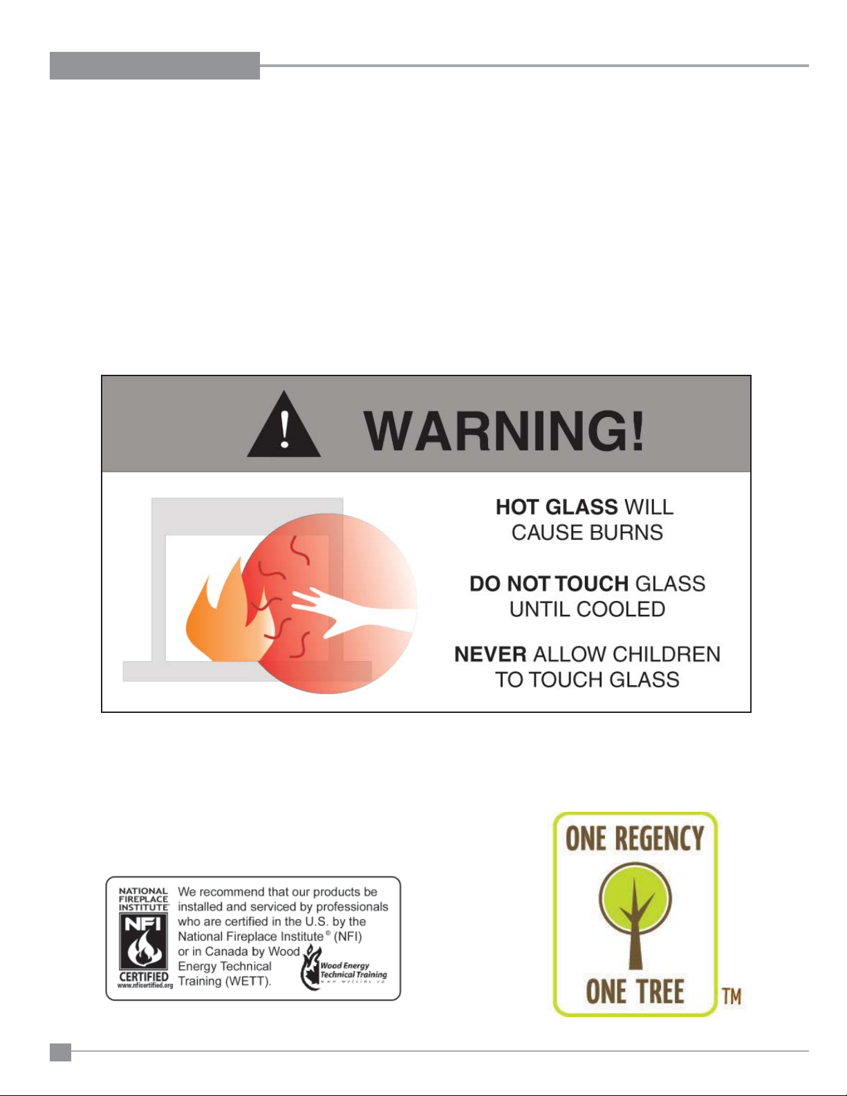
CHILDREN AND ADULTS SHOULD BE
ALERTED TO THE HAZARDS OF HIGH
SURFACE TEMPERATURES, ESPECIALLY THE FIREPLACE GLASS, AND
SHOULD STAY AWAY TO AVOID BURNS
OR CLOTHING IGNITION.
CLOTHING OR OTHER FLAMMABLE
MATERIAL SHOULD NOT BE PLACED
ON OR NEAR THE APPLIANCE.
IMPORTANT MESSAGE
SAVE THESE
INSTRUCTIONS
The Regency® Gas Fireplace must be installed in
accordance with these instructions. Carefully read
all the instructions in this manual fi rst. Consult the
"authority having jurisdiction" to determine the need
for a permit prior to starting the installation. It is the
responsibility of the installer to ensure this fi replace
is installed in compliance with the manufacturer's
instructions and all applicable codes.
GENERAL SAFETY
INFORMATION
The condition of the appliance, that the E18 is
to be installed into, shall be in accordance with
reasonable concepts of safety, substantiality and
durability. Component parts shall be well fi tted and
not show signs of becoming warped, bent, broken
or otherwise damaged during the installation. Every
part of the appliance shall be secured against
displacement and constructed to maintain a fi xed
relationship between essential parts under normal
and reasonable conditions of handling and usage.
1. The appliance installation must conform with
local codes or, in the absence of local codes,
with the current Canadian or National Gas
Codes, CAN1-B149 or ANSI Z223.1 Installation
Codes.
2. The appliance when installed, must be electrically grounded in accordance with local codes,
or in the absence of local codes with the current
National Electrical Code, ANSI/NFPA 70 or CSA
C22.1 Canadian Electrical Code.
7. This appliance is Listed for Alcove installations,
maintain minimum Alcove clearances as follows,
minimum ceiling height of 37-7/8" from the top
of the glass door, minimum width of 49" and a
maximum depth of 29".
8. Inspect the venting system annually for blockage
and any signs of deterioration.
9. Any safety glass removed for servicing must be
replaced prior to operating the appliance.
10. To prevent injury, do not allow anyone who is
unfamiliar with the operation to use the fi replace
insert.
11. Wear gloves and safety glasses for protection
while doing required maintenance.
12. Ensure adequate combustion and ventilation air.
13. Under no circumstances should this appliance
be modifi ed. Parts that have to be removed for
servicing should be replaced prior to operating
this appliance.
14. Installation and any repairs to this appliance
should be done by a qualifi ed service person. A
professional service person should be called to
inspect this appliance annually. Make it a practice
to have all of your gas appliances checked
annually.
15. Do not slam shut or strike the glass door.
16. Under no circumstances should any solid fuels
(wood, paper, cardboard, coal, etc.) be used in
this appliance.
17. The appliance area must be kept clear and free
of combustible materials, (gases and other fl ammable vapours and liquids).
18. Do not use this appliance if any part has been
under water. Immediately call a qualifi ed service
technician to inspect the appliance and to replace
any part of the electrical control system and any
gas control which has been under water.
YOUNG CHILDREN SHOULD BE CAREFULLY SUPERVISED WHEN THEY ARE
IN THE SAME AREA AS THE APPLIANCE. TODDLERS, YOUNG CHILDREN
AND OTHERS MAY BE SUSCEPTIBLE
TO ACCIDENTAL CONTACT BURNS. A
PHYSICAL BARRIERS IS RECOMMENDED IF THERE ARE AT RISK INDIVIDUAL
IN THE HOUSE. TO RESTRICT ACCESS
TO A FIREPLACE OR STOVE, INSTALL
AN ADJUSTABLE SAFETY GATE TO
KEEP TODDLERS, YOUNG CHILDREN
AND OTHER AT RISK INDIVIDUALS OUT
OF THE ROOM AND AWAY FROM HOT
SURFACES.
Regency® E18 Gas Fireplace Insert
3. See general construction and assembly instructions. The appliance and vent should be
enclosed.
4. This appliance must be connected to the specifi ed vent and termination cap to the outside of
the building envelope. Never vent to another
room or inside a building. Make sure that the
vent is installed as per Venting instructions.
5. This appliance may only be installed in a vented,
solid fuel burning masonry, in any of the approved zero clearance gas appliances listed in
this manual, or as a zero clearance appliance
with the zero clearance kit.
6. This appliance is Listed for bedroom installations
when used with a Listed Millivolt Thermostat.
Outside combustion air supply is also required.
Some areas may have further requirements,
check local codes before installation.
19. WARNING: Failure to position the parts
in accordance with the diagrams in
this manual or failure to use only parts
specifi cally approved with this appliance
may result in property damage or
personal injury.
20. WARNING: Operation of this appliance
when not connected to a properly
installed and maintained venting system
or tampering with the blocked vent shutoff system can result in carbon monoxide
(CO) poisoning and possible death.
Emissions from burning wood or gas could
contain chemicals known to the State of
California to cause cancer, birth defects or
other reproductive harm.
7
Page 8

INSTALLATION
POLICY FOR SOLID FUEL
BURNING &
FACTORY BUILT
FIREPLACES
The Regency® E18 may be installed and vented
into any solid fuel fi replace that has been installed
in accordance with the National, Provincial and
local building codes and is constructed of noncombustible materials.
1. Installer must mechanically attach the supplied
label to the inside of the fi rebox of the fi replace
into which the gas fi replace insert is installed.
"WARNING: This fi replace has been converted
for use with a gas fi replace insert only and
cannot be used for burning wood or solid fuels
unless all original parts have been replaced,
and the fi replace re-approved by the authority
having jurisdiction."
2. If the factory-built fi replace doesn't have gas
access hole(s) provided, an access hole of
1-1/2" (37.5mm) or less may be drilled though
the lower sides or bottom of the fi rebox in a
proper workmanship like manner. This access
hole must be plugged with a non-combustible
insulation after the gas supply line has been
installed.
3. The fi replace fl ue damper can be fully blocked
open or removed for installation of the gas
fi replace insert.
4. The fi replace and fi replace chimney must be
clean and in good working order and constructed of non-combustible materials.
5. The chimney cleanouts must fi t properly.
6. Refractory (fi rebricks), glass doors, screen
rails, screen mesh and log grates can be
removed from the fi replace before installing
the gas fi replace insert.
7. Smoke shelves, shields and baffl es may be
removed if attached by mechanical fasteners.
If any part is removed it must not weaken the
structural integrity of the factory built.
8. Trim panels or surrounds shall not seal ventilation openings in the fi replace.
9. Do not cut any sheet-metal parts of the fi re-
place, in which the gas fi replace insert is to
be installed.
INSTALLATION
CHECKLIST
1. Locate your appliance. Refer to the "Clear-
ances to Combustibles" and "Minimum
Fireplace Clearances" sections.
2. Make gas and electrical connections. Refer
to the "Gas Connection" section.
Test the pilot. Must be as per diagram in the
"Valve Description" section.
3. Install Flue Connector. Refer to the "Flue
Connector Installation" section.
4. Install vent. Refer to the "Venting" section.
5. Test Gas pressure. Refer to the "Gas Pipe
Pressure Testing" section.
Check aeration. Refer to the "Gas Insert
Aeration System" section.
6. Test for fl ue spillage. Refer to the "Test for
Flue Spillage" section.
7. Install standard and optional features. Refer
to the following sections where applicable:
a. Brick or Enamel Panels
b. Faceplate & Trim
c. Circulation Fan
d. Remote Control
e. Wall Switch
f. Wall Thermostat
8. Final check. Refer to the "Final Check"
section.
Before leaving this unit with the customer,
the installer must ensure that the appliance is
fi ring correctly and operation fully explained to
customer.
This includes:
1. Clocking the appliance to ensure the correct
fi ring rate (rate noted on label) after burning
appliance for 15 minutes.
2. If required, adjusting the pr imary air to ensure
that the fl ame does not carbon. First allow
the unit to burn for 15-20 min. to stabilize.
3. Ensure that the appliance is venting correctly.
CAUTION: Any alteration to the product that
causes sooting or carboning that results
in damage is not the responsibility of the
manufacturer.
Specifi cations
For Altitude: Natural Gas 0-4500 ft.
Propane: 0-4500 ft.
Burner Orifi ce Sizes:
Natural Gas Propane
Burner #44 #55
Max. Input Rating
- Natural Gas 21,600 Btu/h
- Propane 20,500 Btu/h
Min. Input Rating
- Natural Gas +/-5% 15,000 Btu/h
-Propane +/-5% 17,000 Btu/h
Supply Pressure
Natural Gas min. 5.0" w.c.
Propane min. 12.0" w.c.
Manifold Pressure (High)
Natural Gas 3.5" +/- 0.2" w.c.
Propane 10" +/- 0.2" w.c.
Circulation Fan: 120 VAC, 60 Hz
Variable Speed: 127 CFM, thermally
actived
AIR SHUTTER
ADJUSTMENT
The aeration adjustment rod is attached to the
air shutter which is located just above the orifi ce
bracket. The rod is used to adjust the aeration
on the main burner without having to take the
appliance apart.
The burner aeration is factory set but may need
adjusting due to either the local gas supply, air
supply or altitude.
Natural Gas: 3/16" open
Propane: Fully Open
Note: Any damage due to carboning
resulting from improperly setting
the aeration controls is NOT covered
under warranty.
Note: Aeration Adjustment should only be
performed by an authorized Regency®
Installer at the time of installation or
service.
HIGH ELEVATION
This unit is approved in Canada for altitude
0 to 4500 ft. (CAN/CGA 2.17-M91)
8
Regency® E18 Gas Fireplace Insert
Page 9
INSTALLATION
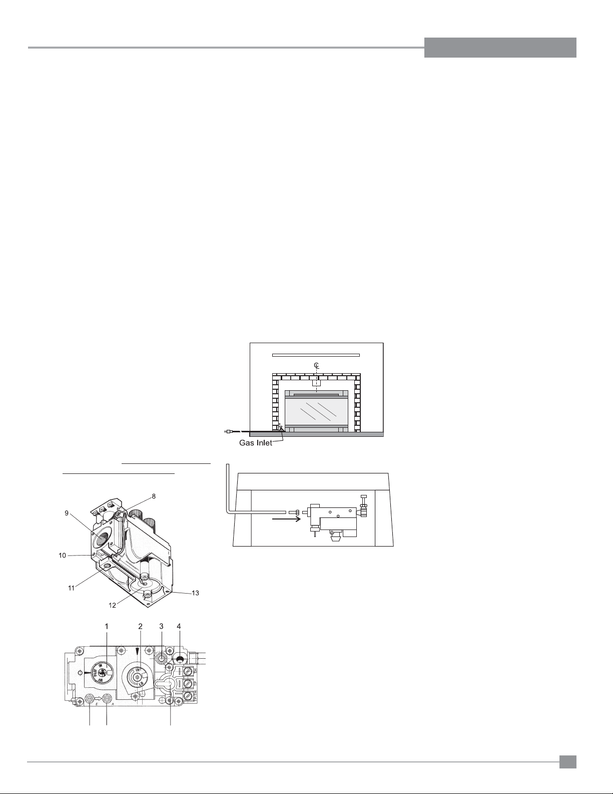
GAS PIPE
PRESSURE TESTING
The appliance must be isolated from the gas
supply piping system by closing its individual
manual shut-off valve during any pressure
testing of the gas supply piping system at test
pressures equal to or less than 1/2 psig. (3.45
kPa). Disconnect piping from valve at pressures
over 1/2 psig.
The manifold pressure is controlled by a
regulator built into the gas control, and should
be checked at the pressure test point.
Note: To properly check gas pressure, both
inlet and manifold pressures should
be checked using the valve pressure
ports on the valve.
1. Make sure the valve is in the "OFF" position.
2. Loosen the "IN" and/or "OUT" pressure
tap(s), turning counterclockwise with a 1/8"
wide fl at screwdriver.
3. Attach manometer to "IN" and/or "OUT"
pressure tap(s) using a 5/16" ID hose.
4. Light the pilot and turn the valve to "ON"
position. Read manometer.
5. The pressure check should be carried out
with the unit burning and the setting should
be within the limits specifi ed on the safety
label.
For minimum and maximum supply pressure
see the Specifi cations table.
1. If the appliance is to be installed into an
existing chimney system, thoroughly clean
the masonry fi replace that has been chosen
for the Regency
2. The appliance is provided with an opening
on the left hand side of the control
compartment for the gas line.
Note: During any pressure testing of the
gas supply piping system that exceeds test
pressures of 1/2 psig, this appliance and its
individual shut-off valve must be disconnected
from the piping system. If test pressures equal
to or less than 1/2 psig are used then this
appliance must be isolated from the piping
system by closing its individual manual shut-off
valve during the testing.
CAUTION: If the glass is removed for
servicing, it must be replaced prior to
operating the appliance. The glass must be
fi xed in the closed position when operating.
®
Gas Fireplace.
GAS CONNECTION
Only persons licensed to work with gas piping
may make the necessary gas connections to
this appliance.
The gas connection is a 1/2" NPT accessible on
the left side of the unit. The gas line connection
may be made of rigid pipe, copper pipe or an
approved fl ex connector. (If you are using rigid
pipe, ensure that the valve can be removed
for servicing.) Since some municipalities have
additional local codes it is always best to consult
with your local authorities and the CAN/CGA
B149 installation code.
For USA installations follow local codes and/
or the current National Fuel Gas Code, ANSI
Z223.1.
When using copper or fl ex connectors use only
approved fi ttings. Always provide a union so that
gas lines can be easily disconnected for burner
or fan servicing. Flare nuts for copper lines and
fl ex connectors are usually considered to meet
this requirement.
Important: Always check for gas leaks
with a soap and water solution or gas
leak detector. Do not use open fl ame
for leak testing.
6. When fi nished reading manometer, turn
off the gas valve, disconnect the hose and
tighten the screw (clockwise) with a 1/8"
fl at screwdriver. Note: Screw should be
snug, but do not over tighten.
Diagram 2.2
Diagram 2.3
Diagram 2.1
Regency® E18 Gas Fireplace Insert
9
Page 10
INSTALLATION
INSTALLATION CHECKLIST
1. Verify the model of the existing appliance you
are installing into is one of the following approved units:
Montigo EP28-2
Montigo EP28-4
Montigo EP28-5
Montigo EP28-S2
Montigo 36SR (Non powervent unit)
Montigo 28F-2
Montigo 28-F
Firesong 220N
Firesong 120N
2. Verify all clearances are at least the specifi ed
clearances.
3. Inspect existing venting and appliance for signs
of wear and durability.
4. Determine the route for the electrical for
the circulation fan. The circulation fan is not
optional.
5. Determine the route for the gas supply. The valve
has a 1/2" Male Flare on the left side of the E18.
Some modifi cation may need to be made to a
hard lined gas supply to connect to the E18.
6. Clean out the existing appliance of all dust and
debris.
7. Make the appropriate modifi cations to the existing
appliance specifi ed in the "Existing Appliance
Modifi cation" section of the manual. Make sure
when done there are no sharp edges exposed
to a person during operation of the unit.
8. Unpack the E18 from the box and disassemble.
9. Install the E18 into the existing unit as per
instructions.
10. Connect Gas Supply.
11. Connect Circulation Fan Power Cord.
12. Test Fire the E18 and check gas pressures
and confi rm Circulation Fan begins operation
with 10 minutes of fi ring the unit.
13. Check draft hood for spillage as per instructions.
14. Install Trim Kit as per instructions.
MATERIALS REQUIRED
Electrical power supply is required for the circulation
fan A 120 Volt AC power cord is hooked up to the
fan. Plug the 3 wire cord into a suitable receptacle. Do not cut the ground terminal off under any
circumstances. When connected with 120 volts,
the appliance must be electrically grounded in accordance with local codes, or in the absence of local
codes, with the current Canadian Electrical Code
CSA C22.1 (in Canada) or with the current National
Electrical Code ANSI/NFPA 70-1987 (in U.S.A.).
NOTE: This unit is equipped with a heat sensor
thermodisc which will prevent the blower
from operating until the unit reaches the
correct temperature.
MINIMUM FIREPLACE
OPENING FOR
MASONRY AND F ACTOR Y
BUILT FIREPLACES
The minimum fi replace opening for this Regency
gas insert are listed below.
Height Depth Width
23-3/8" 12-1/2" 32"
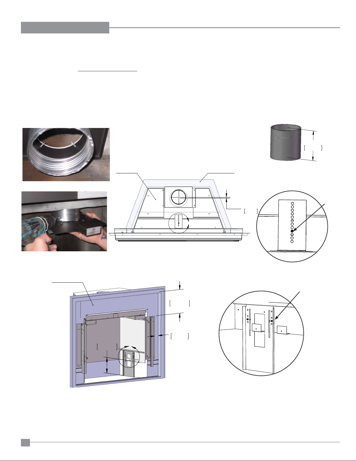
VENTING
THE APPLIANCE MUST NOT BE
CONNECTED TO A CHIMNEY FLUE
SERVING A SEPARATE SOLID FUEL
BURNING APPLIANCE.
This appliance is designed to attach to a 4" diameter
type B-Vent or double thickness approved aluminium
fl ex liner.
The fl ue collar of the appliance will fi t inside a
standard vent and may be fastened directly to the
vent using a minimum of 3 sheet metal screws or
a B-Vent, single wall vent connector.
B-Vent chimneys require a 1" clearance to combustibles.
®
The Regency
draft hood, so no additional external draft hood is
required. Check periodically that the vent is unrestricted and an adequate draft is present when the
unit is in operation.
Before installing the vent system ensure that the
damper plate is locked into the open position and
secure to prevent the damper plate from falling
down and crushing the liner.
The appliance is equipped with a vent safety shutoff
system and a safety control system designed to
protect against improper venting of combustion
products. The appliance will not function without
being connected to a proper system.
Insert incorporates its own internal
WARNING: Operation of this heater when
not connected to a properly installed and
maintained venting system or tampering
with the vent shut-off system can result
in carbon monoxide (CO) poisoning and
possible death.
This appliance must not be connected to a chimney
fl ue serving a separate solid fuel burning appliance.
For best venting performance, we recommend the
following venting rules:
1. Use only certifi ed Type B gas vent or approved
fl ex liner.
2. Follow the vent manufacturer's instructions and
clearance requirements.
3. Observe any local code restrictions, if any,
regarding the installation of gas inserts.
4. Use as few elbows as possible.
5. Keep horizontal lengths as short as possible
and maintain at least an upward slope of 1/4 in.
(6.4mm) for every 12 in. (305mm) of horizontal
run.
6. Terminate the vent with a suitable certifi ed
vent cap.
10
Regency® E18 Gas Fireplace Insert
Page 11
INSTALLATION
MINIMUM FIREPLACE CLEARANCES TO COMBUSTIBLES
Diagram shows the minimum clearances to any combustible material. Installer must check that all installs maintain at least these clearances..
The minimum clearance from the side of the appliance to a combustible
side wall is 6" (229mm). The minimum clearance from the bottom edge
of the front trim above the window to a combustible mantel is 17- 7/8 "
(454 mm). The minimum height from bottom edge of the front trim above
the window to the ceiling is 37-7/8"(962 mm).
PP
PP
PP
PP
PP
Note: A non-combustible mantel and framing may be installed
at a closer tolerance if the framing is made of metal studs
covered with a non-combustible board.
PP
PP
PP
PP
PP
PP
PP
Diagram 3.1
PP
0D[
Diagram 3.2
Regency® E18 Gas Fireplace Insert
PP
GHJ
$OORZDEOH
0DQWOH
DUHD
PP
0LQ
&HLOLQJ
PP
0LQ
)ORRU
6LGHZDOO
0DQWHO
PP
PLQ
PP
0LQ
11
Page 12
INSTALLATION
1. When installing the E18 as a
zero clearance, you will use
the framing clearances in the
following diagrams. Mantel
and inside corner clearances
can be found in Minimum
Clearances to Combustibles.
2. Attach the E18 to the Zero
Clearance Kit.
3. Attach the Zero Clearance Kit
to the Framing.
4. Install the Surround as per
manual.
PP
ZERO CLEARANCE FRAMING
PP
0LQ
PP
0LQ
&HLOLQJ+HLJKW
+HDGHU+HLJKW
7\SLFDO
)UDPLQJ
=HUR&OHDUDQFH
.LW6XUURXQG
)UDPLQJ
(,QVHUW
Diagram 4.1
PP
0LQ
PP
0LQ
&KDVH
'HSWK
PP
0LQ
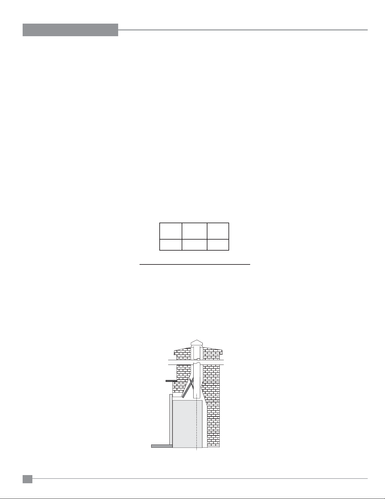
VENTING CONFIGURATIONS
The E18 is approved to be attached to any of the approved appliances listed
in the Installation Checklist. The existing unit must be connect to B-Vent Pipe
having at least 8 feet of vertical venting and can having a maximum of 6 feet
horizontal venting with two 90 degree elbows. The venting must terminate
vertically with an approved B-Vent Cap.
When Installing the E18 as a Zero Clearance Unit, the E18 will connect to
4" B-Vent only. You must use a minimum of 8 feet of vertical pipe and you
may use up to a maximum of 6 feet of horizontal pipe with two 9 degree
elbows. The venting must terminate vertically with an approved B-Vent Cap.
12
All horizontal runs must maintain a 1/4" of rise for every foot of horizontal run.
Diagram 4.2
Regency® E18 Gas Fireplace Insert
Page 13
ZERO CLEARANCE KIT INSTALLATION
INSTALLATION
616-900 E18 ZC Kit contains the following:
1 ZC Left Section
1 ZC Right Section
1 ZC Base Section
1 ZC Back Center Section
1 ZC Trim surround LH
1 ZC Trim surround RH
1 ZC Trim surround Top
1 ZC Lower Trim piece
1 Steel Stud header (required)
26 (904-897) #8 x 9/16" black wafer screws
25 (904-576) #8 x 1/4" Phillips screws
NOTE: Before removing existing unit - ensure ZC kit will fi t.
1. Shut down existing unit and allow to cool to room temperature.
2. Turn off gas supply and disconnect electrical.
3. Remove all accessories from existing unit, ie. glass doors, louvers, etc.
4. Remove any tiles, hearth or surround from existing unit (if required).
5. Disconnect gas supply from existing unit.
6. Cut away a perimeter of drywall around the existing unit to expose the
framing. See example below.
8. Disconnect venting from existing unit - remove carefully to avoid damage.
9. Remove existing unit from framed opening.
10. Measure framed opening and compare to dimension requirements
for ZC kit (noted below).
Remove existing wood header and replace with supplied steel
stud. Supplied stud will be longer than framed opening, adjust to fi t
before installing.
Additional adjustments to framed opening may be required.
35-9/16"
(903mm)
14-1/2"
(369mm)
41"
(1042mm)
Framed opening - Top View
7. Uninstall existing unit from framing.
Remove unit from framing
Regency® E18 Gas Fireplace Insert
Cut drywall
36"
(914mm)
32-1/2"
(825mm)
(961mm)
37-13/16"
Framed opening - Side View
11. Bend ZC kit side pieces as shown and remove knockouts (if required)
before installation.
Bend to 90º
Bend to 90º
secure in place to
supplied steel stud
Remove knockouts
(if required)
Side pieces
13
Page 14
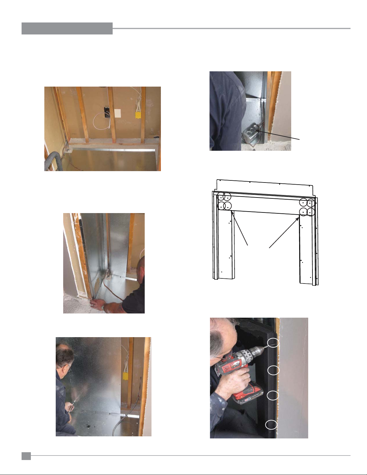
INSTALLATION
12. When framing is complete, ensure wiring is installed by an electrician
prior to installing ZC kit.
13. Install the base of the ZC kit fi rst. Knockout may need to be removed
to accommodate gas line - see below for example.
Base install
14. Install one side section of the ZC kit. Fasten side and back with
(904-576) screws provided. Fasten the header tab (folded in Step
11 to the 2"X4" with 1 screw.
NOTE: Side/back sections–fi t inside base section.
16. Install the remaining side of the ZC kit. Bring the electrical box to the
inside of the ZC kit. Fasten side and back sections with (904-576)
screws provided.
17. Assemble ZC kit surround with 8 (904-897) screws provided in locations shown below.
Sides/Back install
15. Install the back section of the ZC kit. Fasten bottom, back and side
sections with (904-576) screws provided.
Assemble the
ZC box surround
with 4 screws on
each side.
18. Secure surround and outside fl ange of ZC sides to the stud on each side
with (904-897) screws provided.
14
Fasten ZC box sections with provided screws.
Use 4 screws on each side to secure surround
and ZC box to studs.
Regency® E18 Gas Fireplace Insert
Page 15
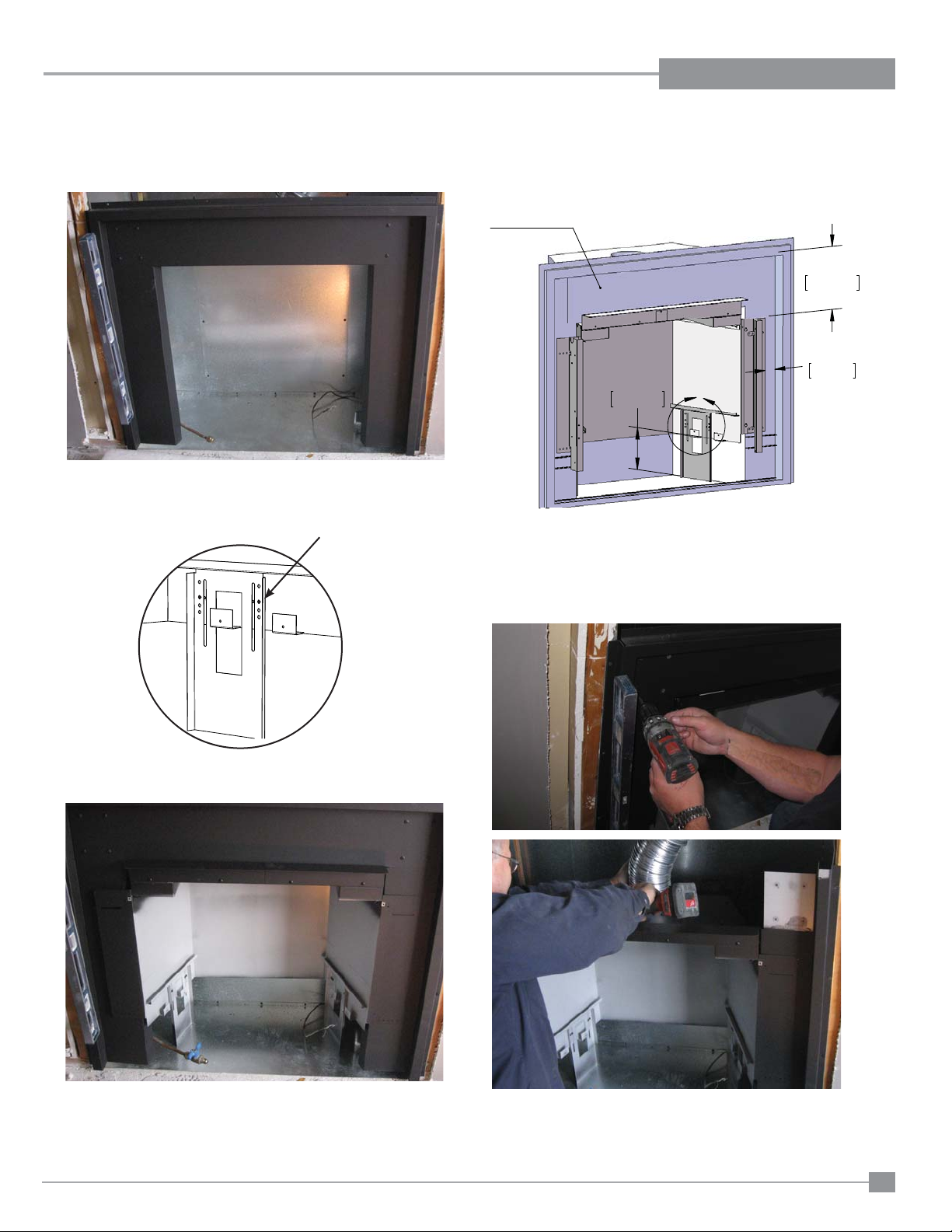
INSTALLATION
J
19. ZC box and surround installed into framed opening.
20. Separate E18 inner and outer fi reboxes - see E18 installation manual
for details.
21. Set E18 outside fi rebox legs as shown below.
Set to this
hole
22. Follow instructions in the manual for installation into a EP28-2 for exact
measurements for installation of the outside fi rebox to the surround.
(3)LUHER[
PP
PP
23. The top panel of the ZC surround may be removed to ease the in-
stallation of the venting - reinstall top panel after venting is installed.
* Extra venting may be required to get inside the ZC box. A 4" fl ex can
be used if required (not provided), if inside ZC shell.
$
PP
/H
Right side shown
Outside fi rebox shown in position - refer to
measurements (Step 22) before securing to surround.
Regency® E18 Gas Fireplace Insert
24. Follow instructions in the E18 installation manual to complete the
install of inner fi rebox.
Follow Step 25 before installing faceplate.
15
Page 16
INSTALLATION
25. Install lower trim piece with 2 (904-897) screws to the bottom of the
ZC surround before installing faceplate.
16
Regency® E18 Gas Fireplace Insert
Page 17
INSTALLATION
REQUIRED STEPS AND PROCEDURES FOR E18 INSTALLATION
1. Locate model on existing ZC box - locate corresponding section in this manual.
2. Make necessary alteration to the ZC fi rebox as per manual.
3. Separate inner and outer fi re box (see procedure in manual).
4. Remove fl ue adaptor for outer fi rebox.
5. Make necessary adjustment to fl ue adapter mounting plate as per manual.
6. Cut fl ex to required length and secure to top plate using 3 screws and washers.
7. Secure top plate fl ue adapter to ZC box.
8. Secure fl ue adapter to fl ex using 3 screws/washers.
9. Slide outer fi rebox into place, be sure fl ue adapter mounting screw doesn't hold unit up on installation.
10. Adjust left and right side lgs on outer shell (depends on ZC box it is being intalled in) - See details in manual.
11. Measure and align outer fi rebox as per manual, secure each corner using self tapping screws.
12. Install inner fi rebox into outer fi rebox, ensure draft hood bottom fi ts on top of draft hood slides, left side, right side and rear.
13. Secure inner fi rebox - 2 screws on top left and right side - using existing holes.
14. Secure inner fi rebox on bottom inside - 2 screws on each side. Be sure to re install panel brackets, and line up with existing holes.
15. Reinstall burner.
16. Make gas connection - check for leaks.
17. Install enamel panels.
18. Install Faceplate
19. Install Glass Crystals on burner.
20. Light pilot.
21. Install glass door.
22. Install thermostat.
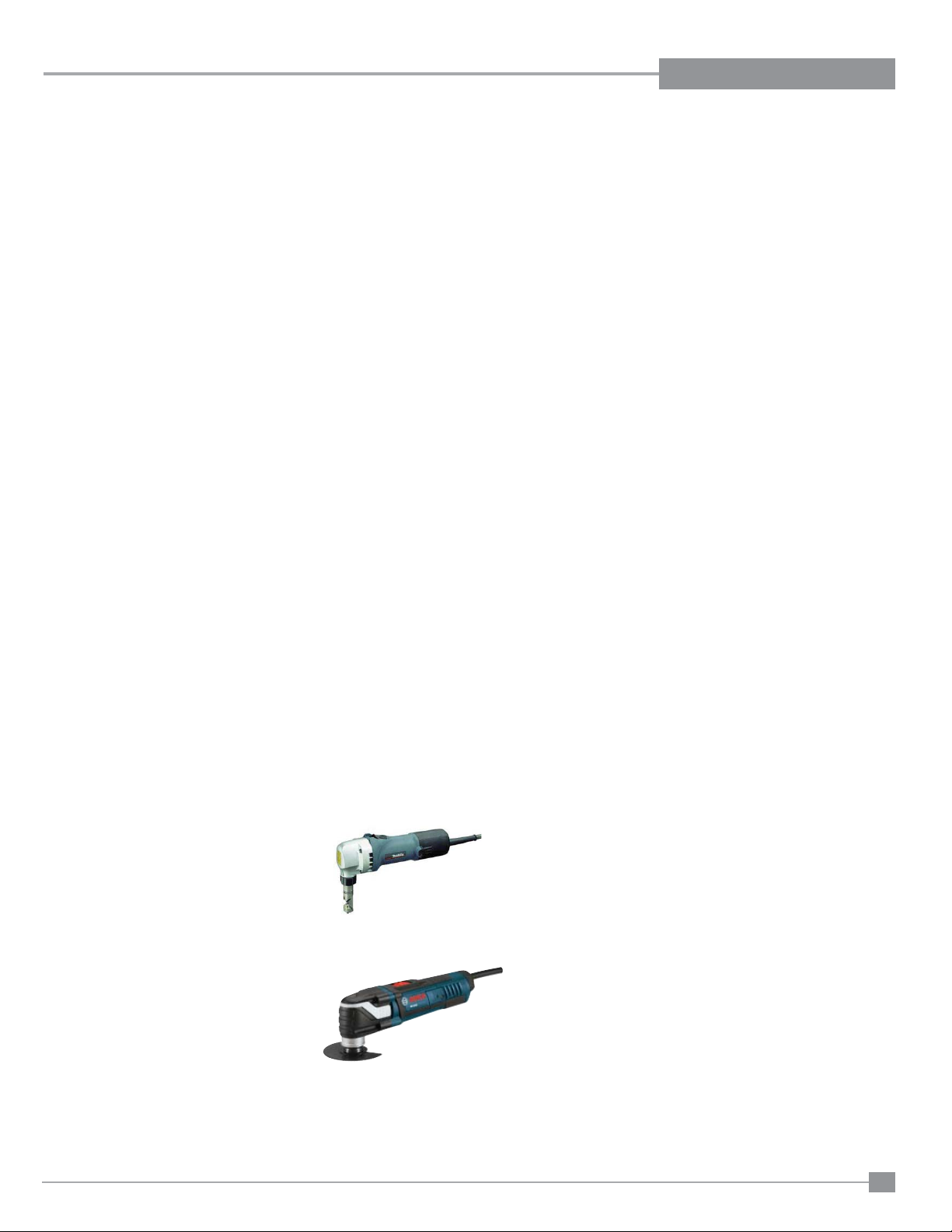
TOOLS REQUIRED (SUGGESTED)
• Nibbler
• Oscillating tool / metal blades
• Tin snips
• Uni Bit/Step Drill
• Black high temp paint
• Drill/ ¼” bit – Phillips bit
• Measuring tape
• Level
• Sharpie
• Shop vacuum
Optional:
• Plasma cutter
• Fibre drop sheet
• Fire extinguisher
Nibbler
Regency® E18 Gas Fireplace Insert
Oscillating tool
17
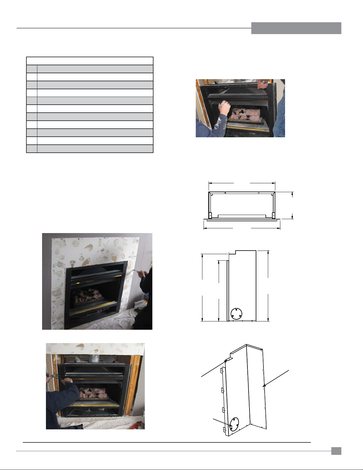
Page 18
INSTALLATION
E18
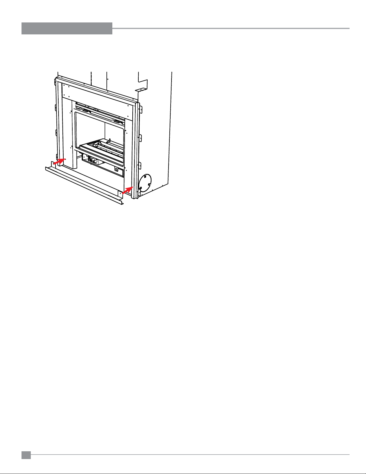
SEPARATING THE OUTER FIREBOX SHELL FROM INNER FIREBOX
1. Lay fi replace insert on fl at surface (use a drop sheet to protect surface).
2. Remove Glass Door by removing 2 x Phillips screws at the bottom of Glass Door Frame.
3. Remove burner by removing 2 x Phillips screws, take note of how aeration adjustment rod is routed.
Burner
4. Remove 2 Phillip screws from top left and right side (Thermodisc bracket).
Remove 2 x 1/4" Hex head screws from top left side and right side of inner fi rebox.
Phillips
Screws
Hex Head
Screws
Aeration adjustment Rod
Remove screws from these locations
5. Remove 4 Phillips crews - 2 per side, located on the bottom base of the fi rebox. Place
screws and panel brackets aside for reinstallation.
6. Carefully lift out the inner fi rebox and set aside until required. Use caution with sleeved
wires on the left side, place inner fi rebox aside.
7. Outer fi rebox shell is ready for installation.
Refer to particular approved appliance in which the E18 is being installed into for the
following:
Existing unit modifi cations
Adaptor setting
Required fl ex length
Leg setting / outer shell position both need to be exact as measurements indicated.
18
Outer shell
Before separating Outer Shell and
Unit—Clear wire harness
Regency® E18 Gas Fireplace Insert
Page 19
INSTALLATION
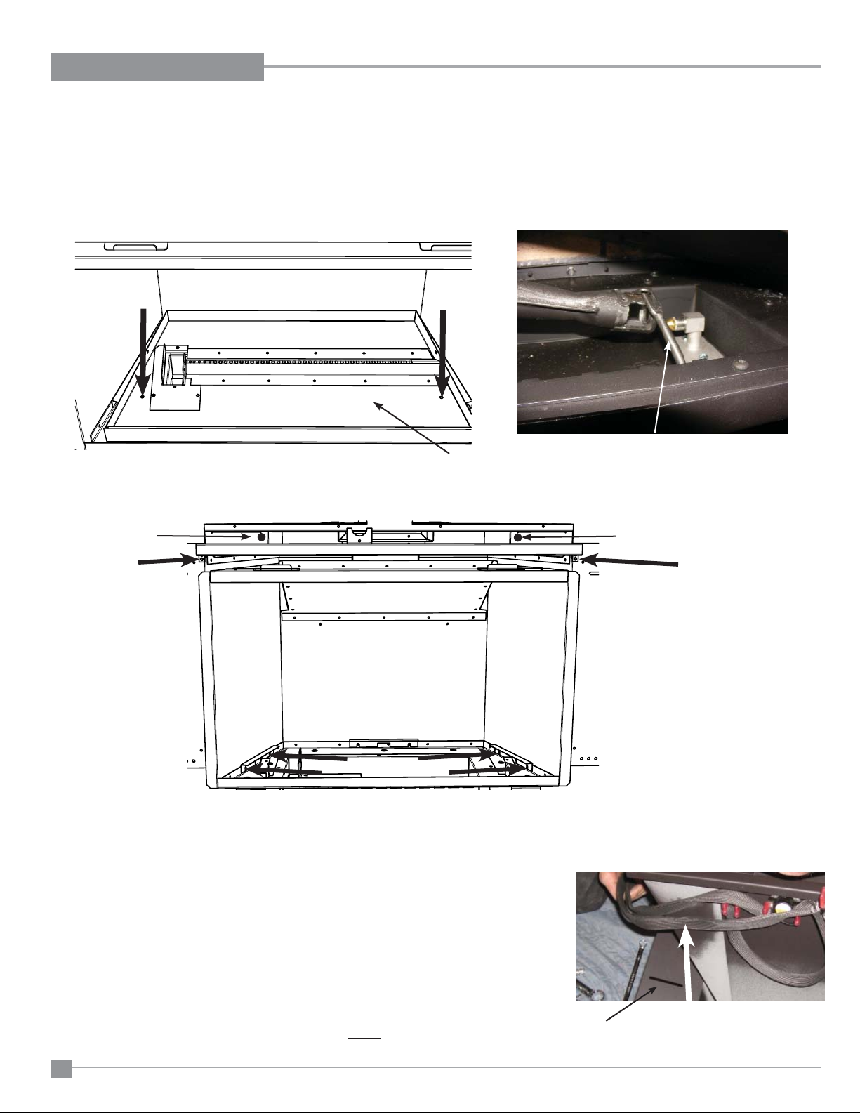
MODIFICATION OF MONTIGO EP28-2, EP28-4
OR EP28-5
*Units could have any of the following Log Sets Installed: 2LB (2 Log Set),
MB (2 Log Set), 4LB (4 Log Set)
1. Turn off unit, disconnect Gas and Power.
2. Remove Upper and Lower Louvers.
3. Remove Optional Doors or Screen Mesh.
4. Remove Logs.
5. Remove Bottom Door Rail (See Diagram 5.1).
6. Remove Burner Assembly (See Diagram 5.1).
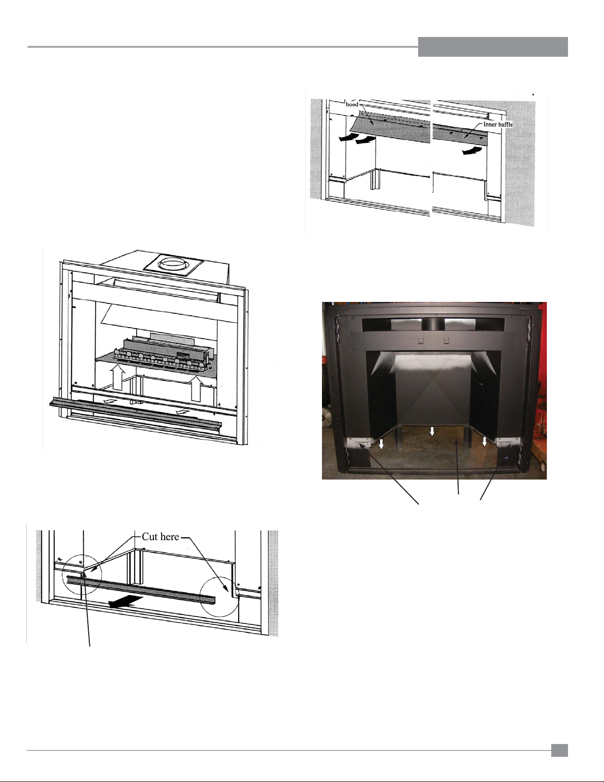
8. Remove Hood and Inner Baffl e (See Diagram 5.3).
Diagram 5.3
9. Bend Down the Three Flanges at the Bottom of the Firebox or cut them
off (See Diagram 5.4).
Diagram 5.1
7. Cut the Front Bar Out on the left and right Sides of the Firebox. (See
Diagram 5.2). Grind the corners smooth on the left side - to reduce the
risk of wires being cut. Alternate method is to cut front bar in the center
and break off each side spot weld completely.
Grind corners
Diagram 5.2
Diagram 5.4
Modidfi ed edges must be fl ush to allow proper seating of the E18
outer shell.
Regency® E18 Gas Fireplace Insert
19
Page 20
INSTALLATION
J
E18 INSTALLATION SPECIFICATIONS
See Installation of E18 into Existing Units for General Installation Guidance - for vent connection confi guration.
This install of the E18 uses
Vent Connection Type A.
The length of 4" Flex needed is 4 -1/8" semi-expanded.
Secure fl ue adapter top plate to under side of existing fi rebox using 4 self tapping screws.
The height of the unit installed is shown below.
EP28-4 / EP28-5 INSTALLATION SPECIFICATIONS
(,QVHUW
Secure top plate to fi rebox w/4 screws.
%
(3)LUHER[
)OH[$GDSWRU/HQJWK
PP
PP
$GDSWRU3ODWH
Set to this
IDVWHQHUVHWWLQJ
'(7$,/%
6&$/(
hole
Secure vent slide plate to fl ex pipe with 4
&ROODU3ODWH6HWWLQJ9HQWSRVLWLRQ
screws
(3)LUHER[
PP
PP
$
PP
/H
Right side shown
1. Loosen 2 x Phillips screws on both right and left legs.
2. See above diagram below for required leg setting.
3 Install with supplied Phillips screws to pre-punched holes and tighten previous screws that were loosened in Step 1.
Set to this
hole
4. Keep left side leg loose until outer fi rebox is in position in ZC box - to allow adjustment of gas line.
20
Regency® E18 Gas Fireplace Insert
Page 21
INSTALLATION
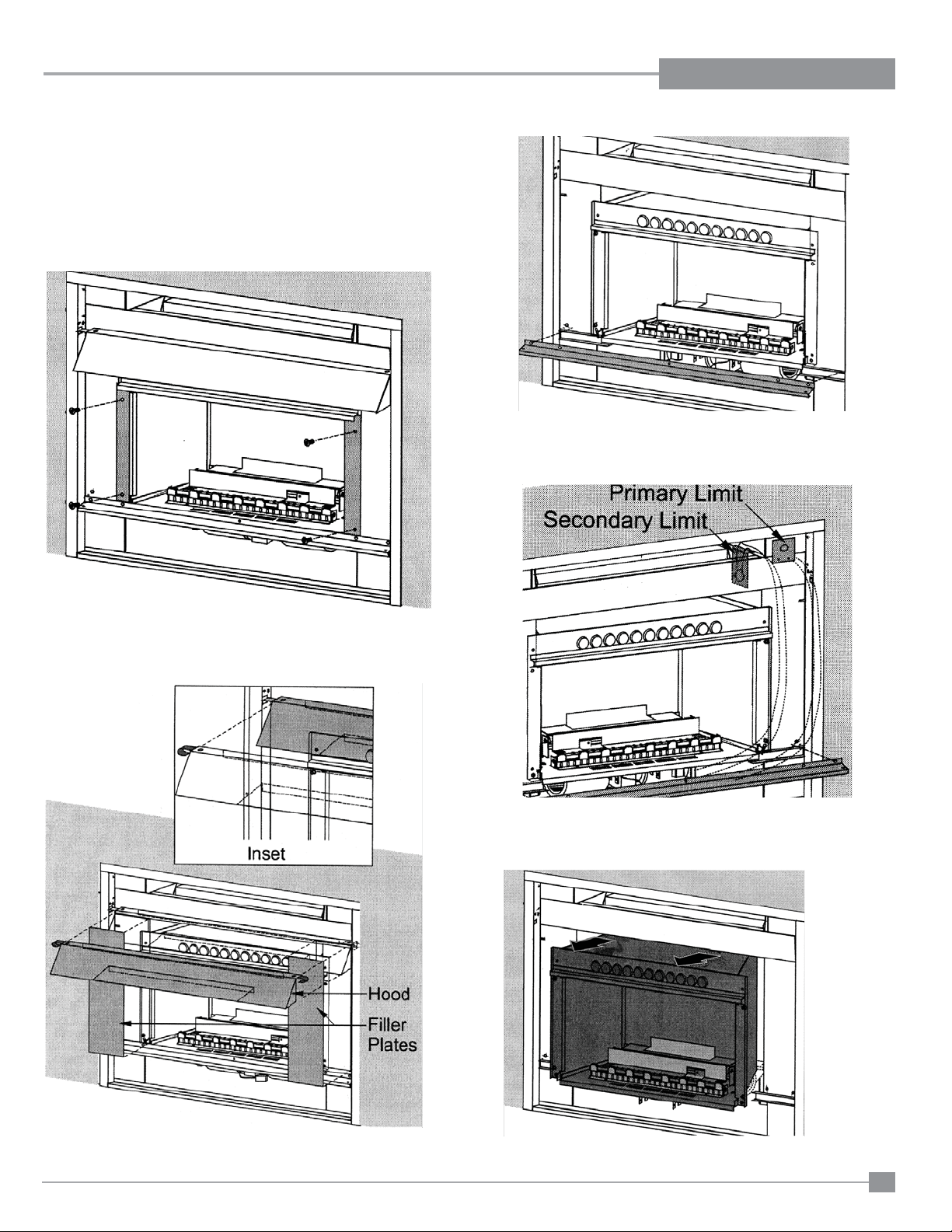
MODIFICATION OF MONTIGO EP28-S2
*S2 Comes with a 6 piece Log Set.
1. Turn off unit and Disconnect Gas.
2. Remove Top and Bottom Louvers.
3. Remove Glass Door (See Diagram 6.1).
5. Remove Front Bar (See Diagram 6.3).
Diagram 6.3
6. Remove Primary and Secondary Limit Switches (See Diagram 6.4).
Diagram 6.1
4. Remove Side Filler Plates and Front Hood (See Diagram 6.2).
Diagram 6.4
7. Remove Insert (See Diagram 6.5).
Diagram 6.2
Regency® E18 Gas Fireplace Insert
Diagram 6.5
21
Page 22

INSTALLATION
8. Remove Effi ciency Collar (See Diagram 6.6).
Diagram 6.6
9. Remove Fan (See Diagram 6.7).
11. Bend Down the Three Flanges at the Bottom of the Firebox or Cut them
Off (see Diagram 6.9).
Diagram 6.9
Edges must be fl ush to allow proper seating of the E18 outerbox.
E18 INSTALL SPECIFICATIONS
Diagram 6.7
10. Remove the leftover ends of the front bar on the Left and Right sides so
that they are fl ush with the sides of the fi rebox. (See Diagram 6.8)
See Installation of E18 into Existing Units for General Installation Guidance.
This install of the E18 uses Vent Connection Type A.
The Length of 4" Flex needed is approximately 4-1/8" semi-expanded.
From this point installation is the same as the EP28-5.
22
Diagram 6.8
Regency® E18 Gas Fireplace Insert
Page 23

INSTALLATION
MODIFICATION OF MONTIGO 28F-2 OR 28-F
1. Turn off unit, disconnect gas and power.
2. Remove Top and Bottom Louvers.
3. Remove Screen Mesh (See Diagram 7.1) or Bifold Doors.
6. Disconnect Pilot Gas Line and Pilot Thermopile from the Valve.
Disconnect Thermostat wires from valve.
Diagram 7.3
7. Disconnect Valve from the Main Burner Line (See Diagram 7.3).
Diagram 7.1
4. Remove Logs and Sand from Sand Pan.
5. Remove Front Bar. (See Diagram 7.2).
Diagram 7.2
Diagram 7.4
8. Unscrew left and right side nuts, under the fi rebox, holding down
the Sand Pan. (see Diagram 7.5)
Regency® E18 Gas Fireplace Insert
Diagram 7.5
23
Page 24

INSTALLATION
9. Remove Sand Pan and Pilot Assembly.
Diagram 7.6
10. Cut out the Bottom of the Firebox (See Diagram 7.7)
Cut must be clean - with Max. 1/4" of material left.
12. Bend Top Face Down (See Diagram 7.9).
Diagram 7.9
13. Measure and draw a line 1" the bottom of the exhaust collar
(See Diagram 7.10).
Diagram 7.10
Diagram 7.7
11. Cut the Sides of the Top Face (See Diagram 7.8).
14. Cut the Sides of the Top of the Firebox Flush with the Sides of
the Firebox and Cut the Top of the Firebox 1” below the bottom of the Exhaust Collar (See Diagram 7.11 and 7.12).
Diagram 7.11
24
Diagram 7.8
Diagram 7.12
Regency® E18 Gas Fireplace Insert
Page 25

INSTALLATION
14. Bend the Louver Mounts Flat. (See Diagram 7.13)
Diagram 7.13
15. Final Firebox Should Look Like Diagram 7.14.
Diagram 7.14
Modifi ed edges must be fl ush to allow proper seating of the E18
outerbox.
Regency® E18 Gas Fireplace Insert
25
Page 26

INSTALLATION
g
e
28 F / 28 F2 INSTALLATION SPECIFICATIONS
E18 INSTALL SPECIFICATIONS
See Installation of E18 into Existing Units for General Installation Guidance for Vent Confi guration.
This install of the E18 uses Vent Connection Type A.
The Length of 4" Flex needed is 2-5/8" semi-expanded. Secure fl ue adapter top plate to under side of existing fi rebox using 4 self taping
screws.
2 5/8"
66mm
Secure top plate to fi rebox w/4 screws.
Secure vent slide plate to fl ex pipe with 4
screws
28-F / 28F-2 Firebox
6 1/16"
155mm
E18 Insert
A
28-F / 28F-2 Firebox
B
Collar Plate Setting / Vent position
7 3/16"
183mm
1 1/2"
39mm
Set to this
hole
Flex Adaptor Length
Set to this
Adaptor Plate
hole
fastener settin
DETAIL B
SCALE 1 : 4
L
Right side shown
1. Loosen 2 x philips screws on both right and left legs.
2. See above diagram below for required leg setting.
3. Install with supplied phillips screws to prepunched holes and tighten previous screws that were loos-
ened in Step 1.
4. Keep left side leg loose until outer fi rebox is in position in ZC box - to allow adjustment of gas line.
26
Regency® E18 Gas Fireplace Insert
Page 27

INSTALLATION
MODIFICATION OF MONTIGO 36SR
1. Turn off and Disconnect Gas and Power.
2. Remove Top and Bottom Louvers.
3. Remove Glass Doors and Screen Mesh (See Diagram 8.1).
Diagram 8.1
6. Remove Air Inlet Strip (See Diagram 8.3).
Diagram 8.3
7. Remove Brick Liner Panels (See Diagram 8.4).
4. Remove Logs and Sand from Sand Pan.
5. Remove Top Rail securing the Bifold Doors (See Diagram 8.2).
Diagram 8.4
8. Unscrew and Remove Trim Around Sand Pan (See Diagram 8.5).
Diagram 8.2
Regency® E18 Gas Fireplace Insert
Diagram 8.5
27
Page 28

INSTALLATION
9. Disconnect Pilot Gas Line and Pilot Thermopile from Valve.
10. Disconnect Valve from Main Burner Gas Line.
11. Remove Plate On the Bottom of the Firebox where Pilot Enters.
(See Diagram 8.6)
Diagram 8.6
12. Unscrew Left and Right Nuts Underneath the Firebox Holding
Down the Sand Pan. (See Diagram 8.7)
14. Unscrew the Bottom of the Firebox. (See Diagram 8.8)
Diagram 8.8
15. Unscrew the Firebox Top Front Flange, making sure to place the
Top Left and right corner screws back in (See Diagram 8.9 and
8.10).
13. Remove Sand Pan and Pilot Assembly.
Diagram 8.7
Diagram 8.9
28
Diagram 8.10
Regency® E18 Gas Fireplace Insert
Page 29

INSTALLATION
16. Remove Louver Supports in all 4 corners of the Appliance (See
Diagram 8.11).
Diagram 8.11 Diagram 8.12
17. Final fi rebox should look like Diagram 8.12.
Modifi ed edges must be fl ush to allow proper seating of the E18
outerbox.
Regency® E18 Gas Fireplace Insert
29
Page 30

INSTALLATION
E18 INSTALL SPECIFICATIONS
See Installation of E18 into Existing Units for General Installation Guidance.
This install of the E18 uses Vent Connection Type A.
The Length of 4" Flex needed is 3" semi-expanded. Secure fl ue adapter top plate to under side of existing fi rebox using 4 self taping
screws.
/HJ6HWWLQJ2XWHU6KHOO3RVLWLRQ
PP
Secure top plate to fi rebox w/4 screws.
Secure vent slide plate to fl ex pipe with 4
screws
65)LUHER[
(,QVHUW
65)LUHER[
%
&ROODU3ODWH6HWWLQJ9HQWSRVLWLRQ
PP
PP
)OH[$GDSWRU/HQJWK
$GDSWRU3ODWH
IDVWHQHUVHWWLQJ
'(7$,/%
6&$/(
Set to this
hole
Set to this
hole
PP
$
PP
/HJK
Right side shown
1. Loosen 2 x philips screws on both right and left legs.
2. See above diagram below for required leg setting.
3. Install with supplied phillips screws to prepunched holes and tighten previous screws that were loosened in Step 1.
4. Keep left side leg loose until outer fi rebox is in position in ZC box - to allow adjustment of gas line.
30
Regency® E18 Gas Fireplace Insert
Page 31

INSTALLATION
MODIFICATION OF FIRESONG 220N
1. Turn off and Disconnect Gas and Power.
2. Remove Valve Cover (See Diagram 9.1).
4. Unscrew and Remove Front Inner Baffl e (See Diagram 9.3).
Diagram 9.3
5. Cut the Sides of the Rear Inner Baffl e at the Back of the Firebox
(See Diagram 9.4).
Diagram 9.1
3. Remove the Bottom of the Firebox and Sand Pan in one assembly (See Diagram 9.2).
Diagram 9.4
6. Bend the Inner Rear Baffl e up so it is fl ush with the back of the
Firebox or cut off the Baffl e if it will not bend fl at with the back of
the Firebox.
Diagram 9.2
Regency® E18 Gas Fireplace Insert
31
Page 32

INSTALLATION
7. Cut The Top Front Flange of the Firebox (See Diagram 9.5).
Diagram 9.5
8. Cut off support tab at the top of the fi rebox and fi nal fi rebox
should look like Diagram 9.6.
Diagram 9.6
Modifi ed edges must be fl ush to allow proper seating of the
E18 outerbox.
32
Regency® E18 Gas Fireplace Insert
Page 33

INSTALLATION
g
Q
E18 Install Specifi cations
See Installtion of E18 into Existing Units for General Installation Guidance.
This install of the E18 uses Vent Connection Type A..
The Length of 4" Flex needed is 1-15/16" semi-expanded. Secure fl ue adapter top plate to under side of existing fi rebox using 4 self tap-
ing screws.
PP
/HJ6HWWLQJ2XWHU6KHOO3RVLWLRQ
PP
Secure top plate to fi rebox w/4 screws.
Secure vent slide plate to fl ex pipe with 4
screws
Firesong 220N Firebox
5 - 3/16"
[132mm]
5 1/4"
133mm
(,QVHUW
E18 Insert
C
)LUHVRQJ1)LUHER[
9HQWVRQFHQWHU
'
&ROODU3ODWH6HWWLQJ9HQWSRVLWLRQ
Firesong 22N faceplate is an outside fi t, if the front metal face
8 3/16"
208mm
of the 220N is covered with stone or tile - a custom faceplate
will be required.
The following measurements of the 220N metal face will be
visible if no stone or tile is covering it. If this metal face is visible, the standard Faceplate (6161-920) will fi t.
Set to this
hole
)OH[$GDSWRU/HQJWK
'(7$,/'
6&$/(
Firesong 220N
Front Facing measurements
Set to this
hole
$GDSWRU3ODWH
)DVWHQHU6HWWL
3"
(76mm)
Note: this measurement
is above lower area
Leg hei
2 1/8"
54mm
1. Loosen 2 x philips screws on both right and left legs.
Leg Setting / Outer Shell Position
Right side shown
2. See above diagram below for required leg setting.
3. Install with supplied phillips screws to prepunched holes and tighten previ-
ous screws that were loosened in Step 1.
4. Keep left side leg loose until outer fi rebox is in position in ZC box - to allow
adjustment of gas line.
Regency® E18 Gas Fireplace Insert
1"
(25mm)
3"
(76mm)
33
Page 34

INSTALLATION
MODIFICATION OF FIRESONG 120N
1. Turn off gas supply, if unit has a fan - turn off and disconnect power.
2. Remove Top Trim Pieces and Glass Doors- if installed (See
Diagram 1.1).
Diagram 1.1
3. Remove Lower Trim piece and Bottom Panel. (See Diagram 1.2).
5. Shut off and disconnect gas line from valve.
6. Unscrew and Remove Trim Around Sand Pan (See Diagram
1.4).
Diagram 1.4
7. Remove Logs (See Diagram 1.5).
Diagram 1.2
4. Remove Top Rail securing Mesh. (See Diagram 1.3).
Diagram 1.5
8. Remove screw on right side to remove sand pan and base.
(See Diagram 1.6).
Diagram 1.6
9. Remove Valve.
10. Make 2 vertical cuts on Top Facing. (See Diagram 1.7).
34
Diagram 1.3
Diagram 1.7
Regency® E18 Gas Fireplace Insert
Page 35

INSTALLATION
11. Remove Top Front Flange of Firesong fi rebox. (See Diagram 1.8).
Remove tabs on right and left side of fi rebox.
Diagram 1.8
12. Cut out mid section of Firesong fi rebox . (See Diagram 1.9).
Cut off bar at back of fi rebox.
14. Cut out right side of existing Firesong fi rebox. (See
Diagrams1.11,1.12 and 1.13). Left and right cutout begins on
front face - see diagram 1.12
IMPORTANT: Cut out Firesong fi rebox and install support one side
at a time.
Diagram 1.11
Back bar
Diagram 1.9
13. Remove 6 screws, one at a time, and replace with pan head
(wafer screws) - in locations shown below.
Diagram 1.12
Diagram 1.10
Regency® E18 Gas Fireplace Insert
Diagram 1.13
35
Page 36

INSTALLATION
15. Install supplied support section with 8 screws to reinforce
Firesong fi rebox. (See Diagram 1.13).
Diagram 1.13
18. Final modifi ed fi rebox should look like Diagram 1.15
NOTE: Shown with fl ue collar and 6" fl ex installed.
Firesong decal affi xed
Diagram 1.15
IMPORTANT NOTE:
Separate inner and outer fi rebox on E18 (see instructions in this
manual) Before installing outer fi rebox - lay on a fl at surface and
trim off 1-1/4" of each fi rebox fastening fl ange as shown below.
16. Repeat Steps 14 & 15 on left side.
17. Remove existing Firesong rating plate from cut out fi rebox.
This rating plate must be retained and affi xed to the unit. (See
Diagram 1.14 and 1.15).
Diagram 1.14
36
Regency® E18 Gas Fireplace Insert
Page 37

INSTALLATION
g
E18 INSTALLATION SPECIFICATIONS
See Installation of E18 into Existing Units for General Installation Guidance - for vent connection confi guration.
The length of 4" Flex needed is 6" semi-expanded.
Remove top fl ue adaptor from unit by removing 1 Philips screw and slide backward. Adjust fl ue adaptor length by resetting screw from Set 4 to Set 8 - see
Diagram below. Attach 4" fl ex to fl ue adaptor and insert into existing 5" vent - shown below.
Procedure to adjust the height of the outer fi rebox installed is shown below.
FIRESONG 120N INSTALLATION SPECIFICATIONS
6"
PP
(152mm)
Firesong 120 fi rebox
(,QVHUW
(3)LUHER[
)OH[$GDSWRU/HQJWK
Secure vent slide plate to fl ex pipe with 4
screws
Firesong 120 Firebox
Firesong 220N Firebox
4-5/8"
5 - 3/16"
[132mm]
[117mm]
5 1/4"
133mm
%
&ROODU3ODWH6HWWLQJ9HQWSRVLWLRQ
E18 Insert
8 3/16"
6-1/8"
208mm
[156mm]
C
PP
$GDSWRU3ODWH
Set to this
IDVWHQHUVHWWLQJ
'(7$,/%
6&$/(
hole
Flue adaptor
setting
Set to this
hole
Leg hei
1/2"
2 1/8"
[13mm]
Right side shown
1. Loosen 2 x Phillips screws on both right and left legs.
2. See above diagram below for required leg setting.
3 Install with supplied Phillips screws to pre-punched holes and tighten previous screws that were loosened in Step 1.
4. Keep left side leg loose until outer fi rebox is in position in ZC box - to allow adjustment of gas line.
See Step #2: Outer Shell installation for procedure.
Regency® E18 Gas Fireplace Insert
37
Page 38

INSTALLATION
INSTALLATION OF THE E18 INTO EXISTING UNITS
STEP #1: VENT CONNECTION TYPE A
1. Attach the Flex Vent Section to the Adaptor Plate using a
Ring Clamp and/or 3 self drilling sheet metal screws.
2. Using 4 Sheet Metal Screws, attach the Adaptor Plate,
Vent Section and Adaptor Plate Gasket to the top of the
existing Fire Box.
See specifi c instructions to your installation to determine what
position the Adaptor Plate should be located.
3. Attach the Slide Plate Retainer to the Vent Slide Plate using the
setting outlined in your unit specifi c installation guide.
4. Using the a ring clamp and/or 3 self drilling sheet metal screws,
attach the Vent Slide Plate to the Flex Vent Section
THE APPLIANCE MUST
NOT BE CONNECTED TO A
CHIMNEY FLUE SERVING
A SEPARATE SOLID FUEL
BURNING APPLIANCE.
Adaptor Plate Gasket
Adaptor Plate
Sheet Metal
Screws
Flex Vent Section
Vent Slide Plate
Slide Plate Retainer
Diagram 10.1
STEP #1: VENT CONNECTION TYPE B
1. Remove the 6x #8 sheet metalscrews from the top of the Vent
Slide Plate.
2. Locate the Adaptor Plate on the top of the Slide Plate
Retainer and attach with 4 x #8 screws removed in the
previous step.
3. Place the Adaptor Plate Gasket on the top of the
Vent Slide Plate
4. Using 4x sheet metal screws, locate and fasten the Vent
Slide Plate assembly to the fi rebox top of the existing fi rebox.
Two (2) screws go through the Vent Slide Plate and Adaptor
Plate, two (2) screws go through the Adaptor Plate only.
$GDSWRU3ODWH
6OLGH3ODWH5HWDLQHU
$GDSWRU3ODWH*DVNHWV
6KHHW0HWDO
6FUHZVIURP
9HQW6OLGH
3ODWH
6KHHW0HWDO
6FUHZV
9HQW6OLGH3ODWH
Diagram 10.2
38
Regency® E18 Gas Fireplace Insert
Page 39

INSTALLATION
H
STEP #2: OUTER SHELL INSTALLATION
1. Slide outer shell back into the existing fi rebox, ensure the vent slide
plate is properly engaged with the outer shell.
Move the outer shell back until the left and right fl anges contact
the existing fi rebox.
2. Adjust the outer shell legs to the setting noted for your specifi c
installation. If these settings are not adhered to, the surround will not fi t
correctly.
3. Attach the bent slide plate to the outer shell with one sheet metal
screw as shown in Figure 10.3. Refer to the applicable existing appli-
ance for correct measurements before securing outer shell in position.
4. Ensure the unit is set at the correct height and the outer shell is square
and centered, fasten the outer shell to the existing fi rebox using self
tapping screws.
STEP #3: FIREBOX INSTALLATION
8SSHU'UDIWKRRG
1. Ensure thermodiscs and thermodisc brackets are in
place.
%DIIOH
:LUH+DUQHVV
([LVWLQJ)LUHER[
/HJ+HLJKW
9HQW6OLGH3ODWH
DWWDFKHPHQWVFUHZ
2XWHU6KHOO6FUHZV[
2XWHU6KHOO/HJV[
)DVWHQLQJ6FUHZV
Diagram 10.3
'UDIWKRRG6OLGH
9HQW6OLGH3ODW
'UDIWKRRG
%RWWRP
2. Install the fi rebox into the outer shell by sliding the
drafthood bottom onto the drafthood slide until you are
able to install 4 screws to secure the fi rebox. Use care
to avoid damaging the wire harness.
Note: 2 of the screws along with panel brackets to be
installed on the lower inside of the fi rebox.
3. Unit is installed correctly when the fl anges that se-
cure the fi rebox to the outer shell contact. Ensure the
unit is centered within the existing fi rebox, attach the
outer shell to the existing fi rebox using 4 x sheet metal
screws.
4. Install 2 self tapping screws at the front edge corners of
the drafthood bottom to secure the drafthood.
5. Install 1 x Phillips screw to fasten drafthood. Install 2 x
Phillips screws to secure left and right side of thermo-
disc bracket.
6XUURXQG
0RXQWLQJ
%UDFNHW
/HIW
&RQWURO%R[
6XUURXQG0RXQWLQJ
%UDFNHW5LJKW
Diagram 10.4
ZC box existing Unit Measured from
Top of ZC box
EP28 8-7/16" (215mm) 1-7/16" (37mm)
28F - 28F2 7-3/16" (183mm) 1-1/2" (39mm)
Montigo 36SR 6-3/8" (162mm) 1-9/16" (40mm)
Firesong 220N 8-3/16" (208mm) 2-1/8" (54mm)
Measured from side of
ZC box
Regency® E18 Gas Fireplace Insert
39
Page 40

INSTALLATION
STEP #4: SURROUND INSTALLATION
ONLY TRIM KIT SUPPLIED BY THE MANUFACTURER SHALL BE
USED IN THE INSTALLATION OF THIS APPLIANCE.
1. Remove glass door from unit (see instructions in manual).
2. Remove control box from rear surround by removing 2 screws.
Disassemble control box, insert switches; reassemble.
Control Box
Rear surround
Diagram 10.5
3. Remove left mounting bracket by removing 3 screws.
5. Attach control box to left mounting bracket with 2 screws - reat-
tach mounting bracket.
6. Tuck wire harness on left top groove and secure with wire clips.
7. Feed power cord through left grommet. (If power outlet is on
the right side of the unit, feed power cord through right grommet and use wire clips to secure power cord inside the unit).
8. Secure backing plate with mounting brackets to outer box by
screwing 4 self tapping screws on fl anges.
Diagram 10.8
9. Attach front faceplate with 4 screws (2 on each mounting
bracket). (Touch up screws with provided black paint, after
install.)
Diagram 10.6
4. Run wire from unit through notch in mounting bracket and then
to control box as shown below.
Notch in
mounting
bracket
Diagram 10.7
40
Diagram 10.9
10. Reinstall glass door (see instructions in manual).
11. Install control cover, adjust horizontal alignment by sliding
control cover to ensure even spacing on both sides. Ensure
control cover is seated down all the way.
Diagram 10.10
DRAFT RELIEF OPENINGS MUST NOT BE COVERED OR BLOCKED.
Regency® E18 Gas Fireplace Insert
Page 41

REMOTE CONTROL INSTALLATION
d
w
m
n
s
e
INSTALLATION
Remote controls approved for use with this appliance:
Part # Remote Function
910-368 Basic Remote ON/OFF
910-399 Firegenie Remote ON/OFF + 7 day programmable
thermostat
946-680 GT Profl ame Remote ON/OFF + Thermostat control
NOTE: Remove bottom control panel on the surround prior to installing
the remote control.
1. S hut off gas and electr ical supply, allow unit to cool to room temperature.
2. If using the GT Profl ame remote control, attach the wire labeled
receiver from the wiring harness to the back side of the remote
receiver. See Diagram 1 below.
Receiver wire harness
GT remote
4. Disconnect red wire from TH terminal on valve - see Diagram 3.
Diagram 3 - Red TH wire disconnected
5. Cut the female wire spade from the disconnected red wire at the en
of connector see Diagram 4.
Bare the same red wire using wire strippers in order to connect ne
male connector, see Diagram 4.
Female wire spade
Diagram 4—cut female wire spade
5a. Crimp on new male connector wire using a crimping tool, see Diagram 5.
Diagram 1
3. Install remote receiver (from any of the approved remote controls)
on the far right hand side of the unit. See Diagram 2 (Basic Remote
receiver shown).
Receiver
Diagram 2—Receiver in position
Strip wire—add male
connector
Diagram 5
6a. Basic or FireGenie remote: Attach one of the two black wires fro
the remote receiver and connect it to the red wire disconnected i
the previous steps, see Diagram 5.
6b. GT remote control: Attach the white wire from the wiring harnes
labeled TP/TH and connect it to the red wire disconnected in th
previous steps, see Diagram 6.
Diagram 6
Regency® E18 Gas Fireplace Insert
41
Page 42

INSTALLATION
7a. Basic or FireGenie remote : Attach the other black wire from the
remote receiver to TH on the valve, see Diagram 7.
7b. GT remote control: Attach the green wire from the wiring harness
labeled TH and attach wire to TH on the valve, see Diagram 7.
Diagram 7
8. Tuck all wires neatly into base of the unit.
9. Locate the red and black ON/OFF switch wires from the appliance,
see Diagram 8.
12. Snap ON/OFF switch into position.
Note: Ensure when snapped into position—the empty
terminal on the back side of the switch is facing upward, see Diagram 9.
13. Code remote control. See remote control manual for coding instructions and battery installation.
Important Note: When remote control is coded, ensure that the ON/OFF
switch is in the on position or facing up and the remote
receiver is in the remote position.
TO TH - TP
ON VALVE
BLACK
WHITE
BLACK
THERMODISC
HI LIMIT
SWITCH
FAN WIRING
ROTARY SPEED CONTROL
GREEN
WHITE
VALVE WIRING
ON/OFF switch wires
Diagram 8
10. Locate the ON/OFF switch, packed in the manual package.
11. Connect ON/OFF switch wires to ON/OFF switch, see Diagram 9.
Empty terminal
ON/OFF switch wires
2 WAY
SWITCH
TO TH
ON VALVE
F/M
F=Female
M=Male
REMOTE CONTROL/WALL THERMOSTAT
RED
BLACK
SPILL
SWITCH
CAUTION: Label all wires prior
to disconnection when servicing
controls. Wiring errors can
cause improper and dangerous
operation.
WARNING: Electrical Grounding Instructions
This appliance is equipped with a three pronged
(grounding) plug for your protection against shock
hazard and should be plugged directly into a properly grounded three-prong receptacle. Do not cut
or remove the grounding prong from this plug.
BLACK
42
Diagram 9
Regency® E18 Gas Fireplace Insert
Page 43

INSTALLATION
CONVERSION KIT 616-969 - NATURAL GAS TO PROPANE
THIS CONVERSION MUST BE DONE BY A QUALIFIED GAS
FITTER IF IN DOUBT DO NOT DO THIS CONVERSION !!
This conversion kit shall be installed by a qualifi ed
service agency in accordance with the manufacturer's instructions and all applicable codes and
requirements of the authority having jurisdiction. If
the information in these instructions is not followed
exactly, a fi re, explosion, or production of carbon
monoxide may result causing property damage,
personal injury, or loss of life. The qualifi ed service
agency is responsible for the proper installation of
this kit. The installation is not proper and complete
until the operation of the converted appliance
is checked as specifi ed in the manufacturer's
instructions supplied with the kit.
LP conversion Kit 616-969
1 904-037 LP orifi ce injector #35
1 904-977 orifi ce #55
1 908-528 Propane Label Red
1 918-590 Converted to LPG label
1 904-529 Allen Key
1 919-191 Instruction Sheet
1. Turn the unit off and allow it to cool to room
temperature.
2. Unplug or disconnect power source to unit.
3. Remove glass front (see manual).
4. Remove Log or Glass Burner. (see manual)
5. Unscrew NG burner orifi ce and replace with
LP orifi ce.
.
9. Insert a 5/32” or 4mm Allen
wrench into the hexagonal
key-way of the screw (Fig. 2),
rotate it counter-clockwise
until it is free and extract it.
Fig.2
10. Check that the screw is clean and if necessary
remove dirt.
11. Flip the screw (Fig. 3).
Fig.3
12. Using the Allen wrench as
shown in Fig.4, rotate the
screw clockwise until snug,
do not overtighten.
14. Re-assemble the black protection cap
(Fig. 6).
Fig. 6
15. Pull off the pilot cap to expose the pilot orifi ce.
16. Unscrew the pilot orifi ce with the allen key and
replace with the LP pilot orifi ce in the kit.
Burner Orifi ce
7. Turn control knob to the “OFF” position
8. Remove the black protection
cap by hand from the hi-low
knob (Fig.1).
Fig. 1
Regency® E18 Gas Fireplace Insert
Fig.4
WARNING!
Do not over tighten the screw.
Recommended to
grip the wrench by the short side.
13. Verify that if the conversion is from NG to LPG,
the screw must be re-assembled with the red
o-ring visible (Fig. 5).
Red o-ring visible
Fig.5
LPG Configuration
17. Attach the label “This unit has been converted
to LPG” near or on top of the serial # decal.
18. Replace yellow “NG” label with red “LPG” label.
19. Reverse steps 3 - 1.
20. Check for gas leaks.
21. Check inlet and outlet pressures.
22. Check operation of fl ame control.
23. Adjust the burner aeration setting to Fully Open
and adjust as required for the best fl ame picture.
24. See manual for Gas Pressure Testing instruc-
tions.
43
Page 44

INSTALLATION
GLASS BURNER INSTALLATION
1. Angle the Glass Burner up on left side and slide the mixing tube
over the orifi ce.
Diagram 11.1
2. Make sure to feed the Air Shutter Bar through the lower hole
in the valve tray, just above the ignitor as you place the Glass
Burner in.
3. Screw down the Glass Burner with two screws.
Diagram 11.3
4. Hang the Front Burner Cover on the front edge.
44
Diagram 11.4
Diagram 11.2
Regency® E18 Gas Fireplace Insert
Page 45

INSTALLATION
ENAMEL PANEL INSTALLATION
Black Enamel Panels
• Black Enamel panels must be inspected for scratches and dimples prior to installation. All claims to be recorded at this time.
Claims for damage after installation will not receive consideration.
• Black Enamel panels will discolor a little during normal operation. This is normal and should not be considered a defect.
All hand and fi nger marks MUST be cleaned off with a soft cloth. Use an ammonia based cleaner (ie. glass cleaner) to remove any fi n-
*
gerprints before applying heat to the unit.
Failure to do this will result in burn stains on panels which you will be unable to remove. Not protected by product warranty.
1. Centre back panel on the back wall of the fi rebox.
2. Slide in side panel into place in lower track.
3. Secure panel in position with panel clip - secure panel clip
with one screw (provided).
Panel Clip
4. Repeat steps 2 & 3 on other side.
Regency® E18 Gas Fireplace Insert
Final Install
45
Page 46

INSTALLATION
GLASS CRYSTALS AND OPTIONAL CERAMIC SPA OR VOLCANIC
STONES INSTALLATION ON BURNER AND FIREBOX FLOOR
Evenly spread the Glass Crystals or optional Ceramic Spa Stones over the burner.
Ensure the crystals (or stones) do not overlap too much as this will effect the fl ame pattern.
IMPORTANT NOTE:
Only the supplied approved Glass Crystals and Ceramic Spa Stones are to be used with these fi replaces. Use of any other type of glass crystals or stones
can alter the unit's performance, any damage caused by the use of any unapproved glass or stones will not be covered under warranty.
When using Ceramic Spa Stones DO NOT cover burner ports or pilot light that lead to pilot fl ame. Ensure the crystals or stones do not overlap excessively
as this will effect the fl ame pattern.
BURNER PACKAGES
Unit *Glass Crystals **Ceramic Spa Stones Volcanic Stones
E18 5 lbs 70 spa stones 1 box
NOTE: * Glass Crystals are available in 1lb and 5lb bags.
** Ceramic Spa stone package contains 70 stones
Diagram 12.1
1. Start installing Crystals on back of
3. Spread Crystals evenly over the
NOTE: Correct fi nal glass installation of Crystals shown in step 3 and 4. The Burner and Firebox Floor should not be visible when the fl ame is out.
Diagram 12.4
burner and fi rebox base
4. Ensure Crystals DO NOT block the
front of the pilot hood and fl ame to
Diagram 12.2
Burner and Firebox Floor
Diagram 12.5
light the burner
2. Distribute Crystals evenly towards
front of Burner and Firebox Floor
Glass Crystals shown on Burner and Firebox Floor
Diagram 12.3
Diagram 12.6
OPTIONAL SPA OR VOLCANICSTONES INSTALLATION (AROUND BURNER)
46
Diagram 12.7
Diagram 12.8
NOTE: Spa or Volcanic Stones are NOT to be placed anywhere on the burner tube or Pilot assembly area.
Regency® E18 Gas Fireplace Insert
Page 47

BRICK PANEL INSTALLATION
INSTALLATION
1. Position back brick panel on the back wall of the fi rebox.
2. Slide in side panel.
5. Repeat steps 2-4 on other side.
Final Install
3. Positon panel so that grout line in the panel lines up with
screw in the baffl e.
4. If required, lower screw to secure panel in position.
Regency® E18 Gas Fireplace Insert
Line up screw and grout line.
47
Page 48

INSTALLATION
s
d
LOG TRAY INSTALLATION
1. Remove the Log Burner Tray from the box. Hang the front
burner cover on the front edge of the burner tray. Place the Log
Burner Tray on the Glass Burner Tray.
2. Screw the Log Burner Tray to the Glass Burner Tray.
LOG SET INSTALLATION
Installation of Panels must be completed before
installing the log set.
* Log instructions shown with Black Enamel Panels
Read the instructions below carefully and refer to the images. If the
are broken do not use the unit until they are replaced. Broken log
interfere with pilot operation.
Improper positioning of the logs may create carbon build-up an
alter the unit's performance which is not covered under warranty.
Log Kit #619-935 contains the following pieces:
A Rear Log
B Front Left Log
C Front Right Log
D Left Side Log
E Right Side Log
946-675 2lb Fireglass
946-669 Platinum Embers
946-708 Embaglow Embers
1C Ember Lava
616-515 Log Tray Assembly
Screws x 2
3. Install the Log Burner the same way as the Glass Burner (see
installation manual for instructions).
4. Fill the Log Burner with 2lbs of black glass crystals.
1. Place Log A over the two posts at the back of the log burne
A
2. Place Log B at the front left of the Log Tray.
A
B
48
Regency® E18 Gas Fireplace Insert
Page 49

. Place Log C at the front right of the log tray.
INSTALLATION
6. Place Log E on the right pin on Log A and on top of Log C.
E
C
. Place ember lava, platinum embers, and embaglow on the
burner, being careful not to cover the pilot or the gas ports.
Ember Lava, Embaglow, Platinum Embers
. Place Log D on the left pin of Log A and the groove in Log B.
B
A
A
E
D
C
Final Install
D
B
Regency® E18 Gas Fireplace Insert
A
49
Page 50

INSTALLATION
OPTIONAL LOG SET INSTALLATION
Read the instructions below carefully and refer to the images. If the logs are broken do not use the unit until they are replaced. Broken
logs can interfere with pilot operation.
Improper positioning of the logs may create carbon build-up and can alter the unit's performance which is not covered under warranty.
*Satin black paint is included if touch ups are required.
1 Rear Log
2 Left Log
3 Right Log
4 Front Center Log Piece
5 Front Left Log Piece
Log Brackets x 2
1
2
3
45
1. S hut off gas and electr ical supply, allow unit to cool to room temperature.
6. Install Rear Log (1), center log and rest on both left and right log
brackets with pins facing up.
1
Rear log in position
7. Install Log 2 by matching pin locator on Log 2 with left pin on Log 1
as shown below.
1
2
2. Remove fl ush glass door (see unit manual).
3. Carefully remove the logs from the packaging and unwrap them.
The logs are fragile, handle with care -never force into position.
4. Ensure glass crystals are installed on the burner.
E18 = 5lbs
5. Install log brackets by clipping brackets to back of burner tray - measure
4" from outside edge of the burner tray to outside edge of bracket.
4"
Brackets installed 4" from outside edge of burner
tray
Log 2 pin locator match
with Log 1 pin
8. Log 2 in position, Log 2 should touch lip of burner approximately 4-1/2"
from the left outside edge of burner tray.
1
2
4-1/2"
Log 2 in position
50
Regency® E18 Gas Fireplace Insert
Page 51

1
2
4
10"
Right Log piece(4) positioned on glass
INSTALLATION
1
5
2
10. Install Log 3 by matching pin locator on Log 3 with right pin on Log
1 as shown below.
1
2
3
4
Installing Log 3
11. Installed Log 3 should touch burner position in the location shown below.
* Measurement taken from left edge of burner tray - approximately 18".
1
Log 5 in position
13. Place lava embers/rocks on glass - ensure rocks do not block pilot.
Do not place lava rocks/embers too close to logs as this may cause
carboning.
14. Adjust aeration, see unit manual for setting.
15. Reverse Steps 2 and 1.
E18 fi nal install
2
18"
Installed position of Log 3
Regency® E18 Gas Fireplace Insert
3
4
51
Page 52

INSTALLATION
GLASS DOOR INSTALLATION
1. Hang Glass Door over the Door Frame Tabs.
2. Two Screws tighten the door on the two lower
Glass Door Tabs.
WARNING:
Do not operate appliance with the glass
front removed, cracked or broken.
Replacement of the glass should be done
by a licensed or qualifi ed service person.
'RRU)UDPH7DE
'RRU)UDPH
Diagram 13.1
SAFETY SCREEN
REPLACEMENT
1. Remove Door as per E18 Installation section
of the manual.
2. Remove the 4 screws to remove Safety
Screen from Door.
3. Reverse order to reattach.
4. Install control cover supplied with screen.
52
6DIHW\6FUHHQ
'RRU5HWDLQHUV6FUHZV
&RQWURO&RYHU
Diagram 13.2
:LQGRZ)UDPH
)DVWHQHUVSODFHV
Diagram 13.3
Regency® E18 Gas Fireplace Insert
Page 53

INSTALLATION
DRAFTHOOD CHECK
A "spillage" test must be made before the installed unit is left with the customer. Follow the
procedure below:
1. Start all exhaust fans in the home and then
close all external doors and windows in the
house. Remove the Front Trim from the E18 to
gain better access to the Drafthood Opening.
Make sure the Glass Door is on properly.
2. Light the unit and set controls to maximum.
3. After fi ve minutes, test that there is a “pull” on
the fl ue by placing a smoke match, cigarette or
similar device which gives off smoke, in front of
the spill tube. See diagram 14.1.
Check for proper draft by placing a match close
to the drafthood opening. This should be checked
after the unit has been operating for 15 min.
The smoke should be drawn into the Drafthood. If
the smoke is still not drawn into the Drafthood turn
the unit off and check for the cause of the lack of
draft. If necessary, seek expert advice.
For wind turbulent sites, a wind cap may remedy
the problem.
Note: The thermally activated safety switch will
sense the change in temperature and shut down
the gas valve in the event of a severe downdraft
or a blocked or disconnected vent. The switch
acts as a safety shut-off to prevent a build-up
of carbon monoxide. If the fl ue is blocked or
has no "draw", the switch will automatically
shut off the supply of gas within 5 - 10 minutes.
Tampering with the switch can result in carbon
monoxide (CO) poisoning and possible death.
If the heater turns off because of lack of draft
during the spillage test, check for the cause and
if necessary, seek expert advice.
'UDIWKRRG2SHQLQJ
The thermally actuated safety switch will automatically reset after it has cooled off. The switch
will continue to cycle until the draft problem is
corrected. DO NOT BYPASS OR DISCONNECT
THIS SWITCH.
REMOTE CONTROL
Use the Regency Remote Control Kit approved
for this unit. Use of other systems may void your
warranty.
The remote control kit comes with a hand held
transmitter, a receiver and a wall mounting plate.
1. Choose a convenient location on the wall to
install the receiver and the receptacle box (protection from extreme heat is very important).
Run wires from the fi replace to that location.
Use Thermostat Wire Table.
2. Disconnect the two wires, Red/Black from the
on/off switch. Connect the receiver wires to the
Red/Black wires only.
CAUTION
Do not wire millivolt
wall thermostat wires
to 120V wire.
3. Install 3 AAA alkaline batteries in transmitter
and 4 AA alkaline batteries in the receiver.
Install the receiver and its cover in the wall.
Switch the remote receiver to "remote" mode.
The remote control is now ready for operation.
Note: Transmitter and receiver need to be
programmed.
WALL SWITCH
1) Run the wire through the right or left side inlet
opening. Be careful not to damage the wire.
Note: We recommend a maximum of 15' of wire
but if you wish to go with a longer run,
use the Thermostat Wire Table.
2) Connect the wire to the supplied wall switch
and install into the receptacle box.
CAUTION
Do not wire millivolt
wall switch wire
to 120V wire.
WALL THERMOSTAT
A basic wall thermostat is supplied with the unit,
connect the wires as per the wiring diagram. Use
table below to determine the maximum wire length.
Note: Preferable if the thermostat is installed
on an interior wall.
Regency offers an optional programmable thermostat but any 250-750 millivolt rated non-anticipator
type thermostat that is CSA, ULC or UL approved
may be used.
CAUTION
Do not wire millivolt
wall thermostat wires
to 120V wire.
(6KRZQZLWKIURQWIDFHSODWHUHPRYHG
3URSHU'UDIW
Regency® E18 Gas Fireplace Insert
Diagram 14.1
,PSURSHU'UDIW
Thermostat Wire Table
Recommended Maximum Lead Length
(Two-Wire) When Using Wall
Thermostat (CP-2 System)
Wire Size Max. Length
14 GA. 50 Ft.
16 GA. 32 Ft.
18 GA. 20 Ft.
20 GA. 12 Ft.
22 GA. 9 Ft.
53
Page 54

INSTALLATION
SAFETY SWITCHES
The E18 uses two safety switches to maintain proper operation.
The fi rst is a Spill Switch which will shut off the appliance if continuous spilling of exhaust gas from the drafthood occurs. The spill switch will shut off the
Main Burner but not the Pilot. This switch is resets automatically, if the problem persists the appliance will cycle on and off. If this occurs. shut the unit off and
contact a technician.
The second is a Primary Limit Switch. This switch confi rms that the circulation fan is operating normally. If for any reason the circualtion fan fails, the Primary
Limit Switch will turn off the Main Burner but not the Pilot before the appliance becomes too hot. This switch is automatic resetting, so if the problem persists
you will see your appliance cycling on and off. If this occurs shut the unit off and contact a technician.
OPERATION CONTROLS
FIREPLACE CONTROLS
The E18 has 3 controls for controlling fl ame height, fan
speed and fl ame on/off. The fan on the E18 is designed
to come on once the fi replace has reached a pre-determined temperature, and to go off once the temperature
has dropper following use.
The speed of the fan can be varied by adjusting the Fan
Speed Control dial up or down. These controls are located
to the left side of the Surround Panels.
Providing that the pilot system is in standing mode, the
main burner can be turned on or off by way of a
switch located just below the Fan Speed Control dial.
See the Lighting Instruction section in this manual
for information on lighting the pilot.
The fl ame height can be adjusted from minimum to maxi-
mum by way of an adjustment knob on the Control Valve,
located behind the Access Panel.
The Access Panel is held in place by magnets and can
simply be lifted away from the unit and set aside.
Note: Supplied white cord channel
Use cord channel to obscure cord and keep tidy. The
cord is located on the left hand side of the appliance.
1. Open channel and feed cord through.
2. Peel off backing of cord channel and adhere to hearth.
$FFHVV3DQHO
)DQ6SHHG&RQWURO
2Q2II6ZLWFK
)ODPH&RQWURO
54
Diagram 15.1
Regency® E18 Gas Fireplace Insert
Page 55

OPERATING INSTRUCTIONS
INSTALLATION
FINAL CHECK
Before leaving this unit with the customer, the
installer must ensure that the appliance is fi ring
correctly. This includes:
1. Clocking the appliance to ensure the correct
fi ring rate (rate noted on label) at 15 minutes.
2. If required, adjusting the pr imary air to ensure
that the fl ame does not carbon. First allow
the unit to burn for 15 min. to stabilize.
3. Check for proper draft.
CAUTION
Any alteration to the product that causes
sooting or carboning that results in
damage to the unit is not the responsibility
of the manufacturer and will not be
covered by the warranty.
OPERATING
INSTRUCTIONS
Before operating this appliance, proceed through
the following check list.
1. Read and understand these Instructions
before operating this appliance.
2. Check to see that all wiring is correct and
enclosed to prevent possible shock.
3. Check to ensure there are no gas leaks.
4. Make sure the glass door is in place. Never
operate the appliance with the door glass
removed.
LIGHTING PROCEDURE
NOTE: For all propane units and units
equipped with electric spark boxes, see
"Copy of Lighting Plate Instructions"
section for more details.
IMPORTANT: Gas on/off knob cannot be turned
from "PILOT" to "OFF" unless it is partially
depressed.
1. Open the bottom louver assembly
2. If the control knob is in the "OFF" position
proceed to Step 5.
3. Push in gas control knob slightly and turn
clockwise to "OFF". Knob cannot be turned
from "PILOT" to "OFF" unless knob is pushed
in slightly. Do not force.
4. Wait fi ve minutes to allow gas, that may have
accumulated in the main burner compartment,
to escape. If you do smell gas, follow the
instructions on the front of this manual. If you
don't smell gas continue on to the next step.
5. Turn the gas control counter clockwise to
"PILOT".
6. Push in control knob all the way and hold in.
Continually push and release the black button
on spark igniter until pilot lights. Continue to
hold the control knob in for approximately one
minute, then release the gas control knob. The
pilot fl ame should continue to burn. If the pilot
does not remain lit, repeat operation allowing
a longer period before releasing gas control
knob.
Gas In
7. Turn gas control knob counter clockwise to
"ON".
8. Use the rocker switch to operate main burner.
9. Rotate the variable fl ame control to adjust the
fl ame height higher or lower.
10. Close the bottom louver assembly.
PILOT ADJUSTMENT
Periodically check the pilot fl ames. Correct
fl ame pattern has three strong blue fl ames:
1 fl owing around the thermopile, 1 around
the thermocouple and 1 fl owing across the
burner (it does not have to be touching the
burner).
Note: If you have an incorrect fl ame
pattern, contact your FPI dealer for further
instructions.
Incorrect fl ame pattern will have small,
probably yellow fl ames, not coming into
proper contact with the rear burner or
thermopile or thermocouple.
5. Verify that all venting and the cap is
unobstructed.
6. Verify log placement. If the pilot cannot be
seen when lighting the unit - the logs or the
embers have been incorrectly positioned.
7. The unit should never be turned off and on
again without a minimum of a 60 second
wait.
8. When lighting the appliance, the inside of
the glass may fog up, this will burn off after
a few minutes of operation.
Regency® E18 Gas Fireplace Insert
Shut Off
Hi-Low
Pilot Adjust
TPTH TP TH
Diagram 16.1
Gas Out
SHUTDOWN
PROCEDURE
1. Use the rocker switch to turn off the main burner.
2. Open the bottom louver assembly.
3. Push in the gas control knob slightly and turn
clockwise to "OFF". Do not force.
4. Pilot must be shut off during prolonged non use
periods to conserve fuel.
4. Disconnect all electric power and gas to the
appliance if service is to be performed.
5555
Page 56

OPERATING INSTRUCTIONS
2) Wait fi ve (5) minutes to clear out any gas. If you then smell
gas STOP! follow “B” in the safety information above on
this label. If you don’t smell gas, go to the next step.
3) Turn knob on gas control counterclockwise to
“PILOT”.
4) Push in control knob all the way and hold in. Continually
push and release the black button on spark igniter until
pilot lights. Continue to hold the control knob in for about
1/2 minute after the pilot is lit. Release knob and it will
pop back up. Pilot should remain lit. If it goes out, repeat
steps 1) to 4). If knob does not pop up when released,
stop and immediately call your service technician or gas
supplier. If the pilot will not stay lit after several tries,
turn the gas control knob to “OFF” and call your service
technician or gas supplier.
5) Turn gas control knob counterclock-wise to “ON”.
6) Use rocker switch to operate main burner.
A) This appliance has a pilot which must be lighted by hand.
When lighting the pilot, follow these instructions exactly.
B) BEFORE LIGHTING smell all around the appliance area
for gas. Be sure to smell next to the fl oor because some
gas is heavier than air and will settle on the fl oor.
WHAT TO DO IF YOU SMELL GAS
- Do not try to light any appliance
- Do not touch any electric switch, do not use any phone
in your building.
- Immediately call your gas supplier from a neighbours
phone. Follow the gas supplier’s instructions.
- If you cannot reach your gas supplier, call the fi re
department.
C) Use only your hand to push in or turn the gas control
knob. Never use tools. If the knob will not push in or
turn by hand, don’t try to repair it, call a qualifi ed Service
Technician. Force or attempted repair may result in a fi re
or explosion.
D) Do not use this appliance if any part has been under water.
Immediately call a qualifi ed service technician to inspect
the appliance and to replace any part of the control system
and any gas control which has been under water.
E) This appliance needs fresh air for safe operation and
must be installed so there are provisions for adequate
combustion and ventilation air.
STOP!
Read the safety information above on this label.
LIGHTING INSTRUCTIONS
1) Push in gas control knob slightly and turn clockwise
to “OFF”. Knob cannot be turned from “PILOT” to “OFF”
unless knob is pushed in slightly. Do not force.
FOR YOUR SAFETY READ
BEFORE LIGHTING
This appliance must be installed in accordance with
local codes, if any; if none, follow the National Fuel
Gas Code, ANSI Z223.1/NFPA 54, or Natural Gas and
Propane Installations Codes, CSA B149.1.
Australia: AG601, New Zealand: NZS 5261
WARNING: If you do not follow these instructions
exactly, a fi re or explosion may result causing
property damage, personal injury or loss of life.
Improper installation, adjustment, alteration,
service or maintenance can cause injury or property
damage. Refer to the owner’s information manual
provided with this appliance. For assistance or
additional information consult a qualifi ed installer,
service agency or gas supplier.
TO TURN OFF GAS APPLIANCE
918-475
DO NOT REMOVE THIS INSTRUCTION PLATE
CAUTION: Hot while in operation. Do not touch.
Severe Burns may result. Due to high surface
temperatures keep children, clothing and
furniture, gasoline and other liquids having
fl ammable vapors away. Keep burner and control
compartment clean. See installation and operating
instructions accompanying appliance.
FOR UNITS NOT EQUIPPED WITH ELECTRIC
SPARK BOXES:
FOR ALL PROPANE UNITS AND UNITS EQUIPPED
WITH ELECTRIC SPARK BOXES:
1) Push in gas control knob slightly and turn to “PILOT”
position.
2) Push in control knob all the way and hold in until the pilot
lights up. Continue to hold the control knob in for about
20 seconds after the pilot is lit. Release knob.
3) Push in gas control knob slightly and turn to "ON"
position.
4) Turn ON the fl ame switch.
1) Turn off the fl ame switch.
2) Push in the gas control knob slightly and turn clockwise
to “OFF”. Do not force.
3) Turn off all electric power to the appliance if service is to
be performed.
Pilot must be shut off during prolonged non use periods
to conserve fuel.
FIRST FIRE
The fi rst fi re in your stove is part of the paint curing
process. To ensure that the paint is properly cured,
it is recommended that you burn your fi replace for at
least four (4) hours the fi rst time you use it with the
fan on. When fi rst operated, the unit will release an
odour caused by the curing of the paint, the burning off of any oils remaining from manufacturing.
Smoke detectors in the house may go off at this
time. Open a few windows to ventilate the room for
a couple of hours.
The glass panel may require cleaning after the unit
has cooled down.
DO NOT ATTEMPT TO CLEAN THE
GLASS WHILE IT IS HOT.
Do not use abrasive cleaners on the
glass.
Note: When the glass is cold and the appliance
is lit, it may cause condensation and fog
the glass. This condensation is normal
and will disappear in a few minutes as
the glass heats up.
DO NOT BURN THE APPLIANCE WITHOUT THE GLASS FRONT IN PLACE.
COPY OF LIGHTING PLATE INSTRUCTIONS
56
56
as Inlet
Regency® E18 Gas Fireplace Insert
Page 57

MAINTENANCE
OPERATION
The fan operates automatically, turn the knob on
the side of the faceplate to adjust to the desired
speed. The fan will turn on as the stove comes up
to operating temperature. After the unit has been
turned off and the unit cooled to below a useful heat
output range the fan will shut off automatically. This
fan is required for normal operation, If the fan stops
working at anytime the unit will automatically turn
off after a delay of approximately 15-30 minutes.
NORMAL OPERATING
SOUNDS OF GAS
APPLIANCES
It is possible that you will hear some sounds from
your gas appliance. This is perfectly normal due to
the fact that there are various gauges and types
of steel used within your appliance. Listed below
are some examples. All are normal operating
sounds and should not be considered as defects
in your appliance.
Blower:
Regency® gas appliances use high tech blowers
to push heated air farther into the room. It is not
unusual for the fan to make a "whirring" sound
when ON. This sound will increase or decrease
in volume depending on the speed setting of your
fan speed control.
Burner Tray:
The burner tray is positioned directly under the
burner tube(s) and logs and is made of a different
gauge material from the rest of the fi rebox and body.
Therefore, the varying thicknesses of steel will
expand and contract at slightly different rates which
can cause "ticking" and "cracking" sounds. You
should also be aware that as there are temperature
changes within the unit these sounds will likely
re-occur. Again, this is normal for steel fi reboxes.
Blower Thermodisc:
When this thermally activated switch turns ON
it will create a small "clicking" sound. This is the
switch contacts closing and is normal.
Pilot Flame:
While the pilot fl ame is on it can make a very slight
"whisper" sound.
Gas Control Valve:
As the gas control valve turns ON and OFF, a
dull clicking sound may be audible, this is normal
operation of a gas regulator or valve.
Unit Body/Firebox:
Different types and thicknesses of steel will expand
and contract at different rates resulting in some
"cracking" and "ticking" sounds will be heard
throughout the cycling process.
MAINTENANCE
INSTRUCTIONS
1. Always turn the gas valve to off before cleaning.
For relighting, refer to lighting instructions. Keep
the burner and control compartment clean by
brushing and vacuuming at least once a year.
When cleaning the logs, use a clean soft paint
brush as the logs are fragile and easily damaged.
2. Clean (never when unit is hot) appliance, door
and louvers with a damp cloth. Never use an
abrasive cleaner. The gold louvers (and optional
gold door) may be scratched if abrasives are
used to clean them.
The heater is fi nished in a heat resistant paint
and should only be refi nished with heat resistant paint (not with wall paint). Regency® uses
StoveBrite Paint - Metallic Black #6309.
3. Make a periodic check of burner for proper position and condition. Visually check the fl ame of
the burner periodically, making sure the fl ames
are steady; not lifting or fl oating. If there is a
problem, call a qualifi ed service person.
4. The appliance and venting system must be
inspected before use, and at least annually,
by a qualifi ed fi eld service person, to ensure
that the fl ow of combustion and ventilation air
is not obstructed.
During the annual service call, the burners
should be removed from the burner tray and
cleaned. Replace the embers but do not block
the pilot.
5. Keep the area near the appliance clear and
free from combustible materials, gasoline and
other fl ammable vapours and liquids.
6. Each time the appliance is lit, it may cause
condensation and fog the glass. This condensation and fog is normal and will disappear in
a few minutes as the glass heats up.
Never operate the appliance without
the glass properly secured in place or
with the door open.
7. Verify proper operation after servicing.
8. Periodically check the pilot fl ames, see the
diagrams in the "Valve Description" section.
If you have an incorrect fl ame pattern, contact
your Regency® dealer for further instructions.
WARNING: CHILDREN AND
ADULTS SHOULD BE ALERTED TO
THE HAZARDS OF HIGH SURFACE
TEMPERATURE AND SHOULD STAY
AWAY TO AVOID BURNS OR CLOTHING
IGNITION. YOUNG CHILDREN SHOULD
BE CAREFULLY SUPERVISED WHEN
THEY ARE IN THE SAME ROOM AS
THE APPLIANCE.
CAUTION: ANY SAFETY SCREEN OR
GUARD REMOVED FOR SERVICING AN
APPLIANCE MUST BE REPLACED PRIOR
TO OPERATING THE APPLIANCE.
CLOTHING OR OTHER FLAMMABLE
MATERIAL SHOULD NOT BE PLACED
ON OR NEAR THE APPLIANCE.
LOG REPLACEMENT
The unit should never be used with broken logs. Turn
off the gas valve and allow the unit to cool before
opening door to carefully remove the logs. The pilot
light generates enough heat to burn someone. If
for any reason a log should need replacement, you
must use the proper replacement log. The position
of these logs must be as shown in the diagram
under Log Installation.
NOTE: Improper positioning of logs may create
carbon build-up and will alter the unit’s
performance which is not covered under
warranty.
GLASS GASKET
If the glass gasket requires replacement use Part
# 936-155 to order new gasket.
DOOR GLASS
Your Regency® fi replace is supplied with high
temperature 5mm-Ceramic glass. If your glass
requires cleaning, we recommend using an
approved glass cleaner available at all authorized
dealers. Do not use abrasive materials.
CAUTION & WARNINGS:
* Do not clean when the glass is hot.
* The use of substitute glass will void all
product warranties.
* Care must be taken to avoid breakage of
the glass.
* Do not strike or abuse the glass.
* Do not operate this fi replace without the
glass front or with a cracked or broken
glass front.
* Wear gloves when removing damaged or
broken glass.
* Replacement of the glass panels should be
done by a licensed or qualifi ed service per
son.
GLASS REPLACEMENT
In the event that you break your glass by impact,
purchase your replacement from an authorized
Regency dealer only. Replacement glass (Part
#616-040/P) is shipped already installed into the
door frame. Reinstall as per Glass Door Installation
in the "Glass Door Removal" section.
Regency® E18 Gas Fireplace Insert
57
Page 58

MAINTENANCE
VALVE REPLACEMENT
1. Shut off the gas and electrical supply.
2. Remove Faceplate Control Cover (see instructions in manual).
3. Remove Glass Door (see instructions in manual).
4. Remove Log Set and Embers or crystals and stones (if installed).
5. Remove Burner and Panels (see instructions in this manual).
6. Unplug the TH and TN/TP wires on the front of the Valve.
Diagram 17.1
INSTALLING VALVE
1. Place new valve tray and gasket into position.
2. Reverse Steps 10-1.
3. Check for gas leaks.
7. Disconnect piezo wire from piezo ignitor.
8. Unscrew the 8 screws holding down the Valve Tray.
Diagram 17.2
9. Slide the Valve Tray out about half way giving easier access to the gas
connection at the valve.
Diagram 17.3
10. Disconect the gas line and remove the valve tray.
58
Regency® E18 Gas Fireplace Insert
Page 59

REMOVING THE FAN
IMPORTANT
Disconnect power supply
before servicing.
1. Shut off the gas and electrical supply.
2. Remove Control Cover. (see instructions in manual)
3. Remove Glass Door.(see instructions in manual)
4. Remove Log Set and Embers or crystals and stones (if installed).
5. Remove Burner and Panels (see instructions in manual)
6. Remove Valve Tray - see previous page.
7. Disconnect Ground Wires and unclip Safety Circuit Wires and remove
through Grommet .
MAINTENANCE
Diagram 18.1
8. Loosen 4 screws holding in Air Inlet Baffl e and remove it.
9. Loosen 3 screws holding in the Circulation Fan.
10. Disconnect Power Leads on Fan Motor
Diagram 18.2
11. Reverse Steps to reinstall.
Regency® E18 Gas Fireplace Insert
59
Page 60

MAINTENANCE
WIRING DIAGRAMS
This heater requires a 120V A.C. supply for
operation of the circulation fan which is required
for operation of the fi replace. In case of a power
failure, the fi replace can be turned on but a
thermal safety switch will cut out the appliance
before it gets to hot. The unitl will cycle on
and off as required to stay within temperature
specifi cations.
For NATURAL GAS Units and Units NOT Equipped with DC Spark Boxes
ROTARY SPEED CONTROL
GREEN
WHITE
Caution: Ensure that the wires do
not touch any hot surfaces and are
away from sharp edges.
When connected with 120 volts, the appliance
must be electrically grounded in accordance
with local codes or, in the absence of local
BLACK
THERMODISC
WHITE
codes the current CSA C22.1 (in Canada) or
with the National Electrical Code ANSI/NFPA
70-1987 (in USA).
NOTE: This unit is equipped with a heat
sensor thermodisc which will
prevent the blower from operating
until the unit reaches the correct
temperature.
RED
CAUTION: Label all wires prior
to disconnection when servicing
controls. Wiring errors can
cause improper and dangerous
operation.
BLACK
2 WAY
SWITCH
BLACK
SPILL
SWITCH
WARNING: Electrical Grounding Instructions
This appliance is equipped with a three pronged
(grounding) plug for your protection against shock
hazard and should be plugged directly into a properly grounded three-prong receptacle. Do not cut
or remove the grounding prong from this plug.
Diagram 19.1
HI LIMIT
SWITCH
BLACK
Diagram 19.2
60
Regency® E18 Gas Fireplace Insert
Page 61

PARTS LIST
0DLQ$VVHPEO\
Part # Description Part # Description
1 E18 Body 13 911-118 Primary Limit Switch
2 616-047 Surround Bracket R 910-407 Basic Wall Thermostat
3 911-071 Fan 15 911-116 Fan Controller
4 616-043 Fan Mounting Bracket 16 616-071 Control Box
5 616-515 Log Tray 17 910-246 On/Off Switch
6 616-930 Log Set 18 616-901/2 Brick Panels
White cord channel 19 904-943 Orifi ce Mount
8 616-929 Mesh screen 20 910-190 Piezo Ignitor
9 616-040 Glass door 21 904-946 Gas Orifi ce
10 616-048 Surround Bracket L 22 910-034 Pilot Assembly
11 911-119 Spill Switch 23 616-526 Burner
12 W241050 Fan Switch 24 910-568 Gas Valve
Diagram 20.1
Regency® E18 Gas Fireplace Insert
61
Page 62

PARTS LIST
(3,QVWDOODWLRQ.LW
Diagram 21.1
Part # Description Part # Description
1 616-070 Adaptor plate gasket 7 E18 Body
2 616-069 Adaptor plate 8 616-068 Surround Panel Rear
3 9 616-067 Surround Panel Right
4 904-960 Ring clamp -Installer supplied 10 Magnet and Bracket
5 948-338 Flex Vent Section - Installer supplied 11 616-051 Control Cover
6 616-023 Flue Slider Plate 12
62
Regency® E18 Gas Fireplace Insert
Page 63

PARTS LIST
0RQWLJR)),QVWDOODWLRQ.LW
Part # Description Part # Description
1 616-070 Adaptor plate gasket 7 E18 Body
2 616-069 Adaptor plate 8 616-068 Surround Panel Rear
3 9 616-067 Surround Panel Right
4 904-960 Ring clamp -Installer supplied 10 Magnet and Bracket
5 948-338 Flex Vent Section - Installer supplied 11 616-051 Control Cover
6 616-023 Flue Slider Plate 12
Diagram 22.1
Regency® E18 Gas Fireplace Insert
63
Page 64

PARTS LIST
0RQWLJR65,QVWDOODWLRQ.LW
Diagram 23.1
64
Regency® E18 Gas Fireplace Insert
Page 65

PARTS LIST
)LUHVRQJ1,QVWDOODWLRQ.LW
Diagram 24.1
Regency® E18 Gas Fireplace Insert
65
Page 66

PARTS LIST
Firesong 120N Installation Kit
4
11
3
5
6
11
10
Item Part # Description Item Part # Description
3 Ring Clamp 9 Magnet Bracket (not shown)
4 Flex section 10 Control Cover
5 Adaptor Slide Plate 11 Firesong 120N Firebox supports
6 E18 Chassis
7 Faceplate panel Rear
66
8
8 Faceplate panel Front
7
Regency® E18 Gas Fireplace Insert
Page 67

WARRANTY
Regency Fireplace Products are designed with reliability and simplicity in mind. In addition, our internal Quality Assurance Team carefully inspects each unit
thoroughly before it leaves our facility. FPI Fireplace Products International Ltd. is pleased to extend this limited lifetime warranty to the original purchaser of a
Regency Product. This warranty is not transferable.
The Warranty: Limited Lifetime
The combustion chamber, heat exchanger, burner tubes/pans, logs, brick panels and gold plating (against defective manufacture only) are covered under the Limited Lifetime
Warranty for fi ve (5) years for parts and subsidized labour* and parts only thereafter.
Glass is covered for lifetime against thermal breakage only, parts and subsidized labour* for fi ve (5) years and parts only thereafter from date of purchase.
External casting, surrounds and grills are covered against cracks and warps resulting from manufacturer defects, parts and subsidized labour* for three (3) years from the date
of purchase and parts only thereafter.
Special Finishes - One year on brushed nickel and antique copper full screens and doors. You can expect some changes in color as the product "ages" with constant heating
and cooling. FPI warranties the product for any manufacturing defects on the original product. However, the manufacturers warranty does not cover changing colors and marks,
ie. fi nger prints, etc applied after the purchase of the product. Damage from the use of abrasive cleaners is not covered by warranty.
Electrical and mechanical components such as blowers, switches, wiring, thermodiscs, FPI remote controls, spill switches, thermopiles, thermocouples, pilot assembly components,
and gas valves are covered for two years parts and one year subsidized labour* from the date of purchase. Blowers and valves replaced under warranty are considered repairs and
continue as if new with appliance. ie. twelve (12) months from original purchase date of appliance with a minimum of three (3) months coverage from date of replacement.
FPI venting components are covered parts and subsidized labour* for three (3) years from date of purchase.
Simpson Dura-Vent venting components (Direct Vent units) are covered by Simpson Dura-Vent Inc. warranty.
Repair/replacement parts purchased by the consumer from FPI after the original coverage has expired on the unit will carry a 90 day warranty, valid with a receipt only. Any
item shown to be defective will be repaired or replaced at our discretion. No labor coverage is included with these parts.
Conditions:
Any part or parts of this unit which in our judgement show evidence of such defects will be repaired or replaced at FPI's option, through an accredited distributor or agent provided
that the defective part be returned to the distributor or agent Transportation Prepaid, if requested.
Porcelain/Enamel - Absolute perfection is neither guaranteed nor commercially possible. Any chips must be reported and inspected by an authorized dealer within three days of
installation. Reported damage after this time will be subject to rejection.
It is the general practice of FPI to charge for larger, higher priced replacement parts and issue credit once the replaced component has been returned to FPI and evaluated
for manufacturer defect.
The authorized selling dealer is responsible for all in-fi eld service work carried out on your Regency product. FPI will not be liable for results or costs of workmanship from
unauthorized service persons or dealers.
At all times FPI reserves the right to inspect product in the fi eld which is claimed to be defective.
All claims must be submitted to FPI by authorized selling dealers. It is essential that all submitted claims provide all of the necessary information including customer name,
purchase date, serial #, type of unit, problem, and part or parts requested, without this information the warranty will be invalid.
Exclusions:
This limited Lifetime Warranty does not extend to or include paint, door or glass gasketing or trim.
At no time will FPI be liable for any consequential damages which exceed the purchase price of the unit. FPI has no obligation to enhance or modify any unit once manufactured.
ie. as products evolve, fi eld modifi cations or upgrades will not be performed.
FPI will not be liable for travel costs for service work.
Installation and environmental problems are not the responsibility of the manufacturer and therefore are not covered under the terms of this warranty policy.
Embers, rockwool, gaskets, door handles and paint are not covered under the terms of this warranty policy.
Any unit which shows signs of neglect or misuse is not covered under the terms of this warranty policy.
The warranty will not extend to any part which has been tampered with or altered in any way, or in our judgment has been subject to misuse, improper installation, negligence
or accident, spillage or downdrafts caused by environmental or geographical conditions, inadequate ventilation, excessive offsets, negative air pressure caused by mechanical
systems such as furnaces, fans, clothes dryer, etc.
Freight damage to stoves and replacement parts is not covered by warranty and is subject to a claim against the freight carrier by the dealer.
FPI will not be liable for acts of God, or acts of terrorism, which cause malfunction of the appliance.
Performance problems due to operator error will not be covered by this warranty policy.
Products made or provided by other manufacturers and used in conjunction with the operation of this appliance without prior authorization from FPI, may nullify your warranty
on this product.
Regency® E18 Gas Fireplace Insert
67
Page 68

Register your Regency® warranty online
www.regency-fi re.com
Reasons to register your product online today!
• View and modify a list of all your registered products.
• Request automatic email notifi cation of new product updates.
• Stay informed about the current promotions, events, and special
offers on related products.
Installer: Please complete the following information
Dealer Name & Address: ______________________________________________
___________________________________________________________________
Installer: ___________________________________________________________
Phone #: ___________________________________________________________
Date Installed: ______________________________________________________
Serial No.: __________________________________________________________
Regency and Energy are trademarks of FPI Fireplace Products International Ltd.
© Copyright 2013, FPI Fireplace Products International Ltd. All rights reserved.
Printed in Canada
 Loading...