

Regency Ashling Installation Manual
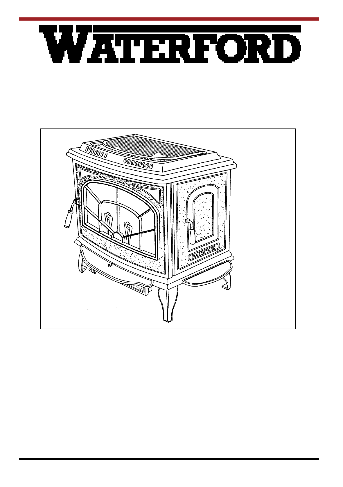
Ashling
WOODBURNING STOVE
SAFETY NOTICE
Please read this entire manual before you install and use your new room heater. Failure to follow instructions may result in property damage, bodily injury or even death.
If this stove is not properly installed, a house fire may result. For your safety, follow the installation directions. Contact local building or fire officials about restrictions and installation inspection requirements in your
area.
Manufactured by Waterford Stanley (Marketing) Limited, Bilberry, Waterford, Ireland.
INSTALLATION & OPERATING INSTRUCTIONS
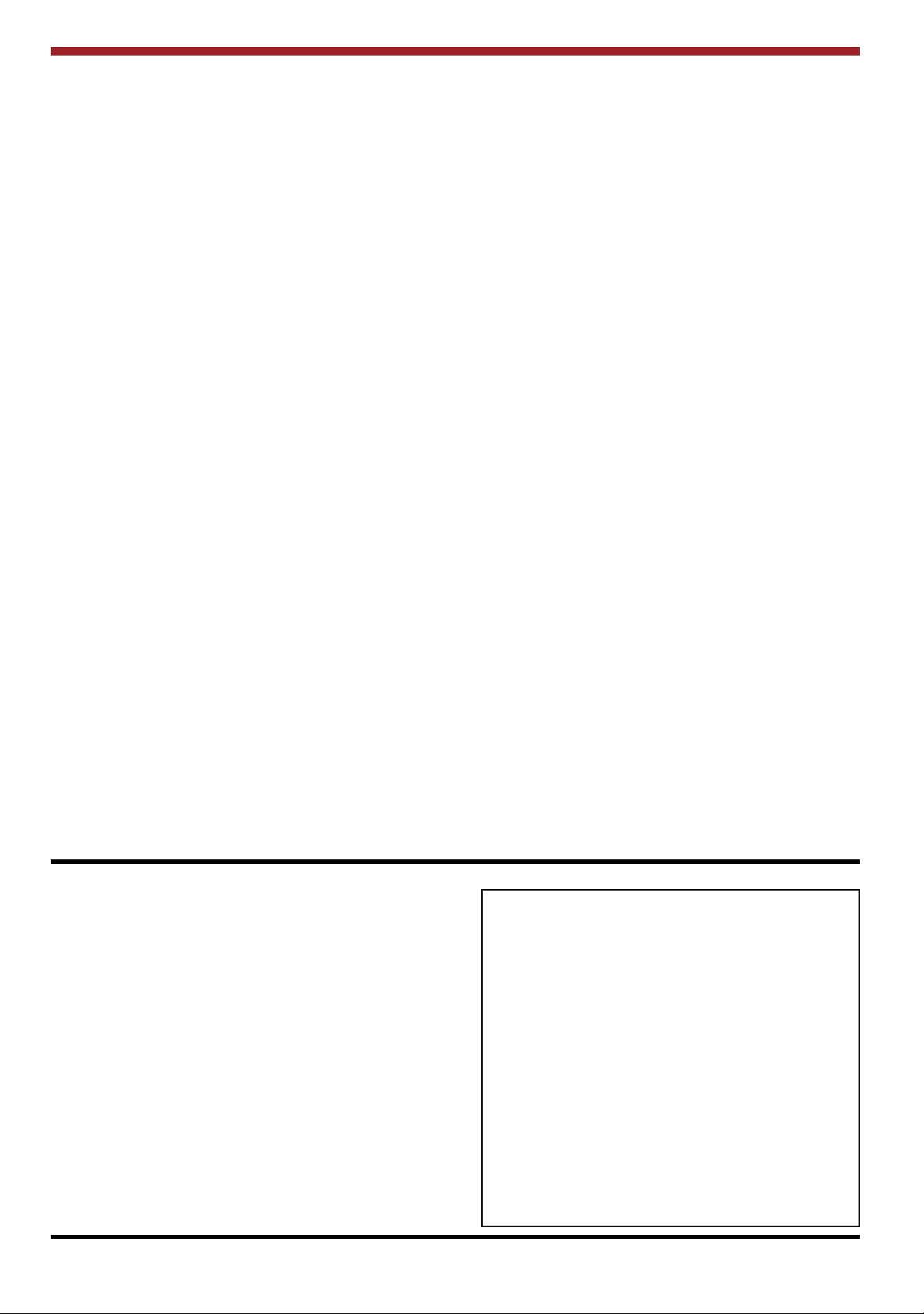
TABLE OF CONTENTS
PAGE NO.
1. Stove Specifications 1
2. General 2
3. Pre-Installation Assembly 2
4. Blower 4
5. Floor Protection 4
6. Location 5
7. Outside Air Connection 5
8. Mobile Home Installation 6
9. Minimum Clearances to Combustibles 7
10. Additional Clearances to Combustibles 8
11. Flooring Requirements 8
12. Exploded View 9
13. Reduced Clearances 10
14. Double Wall Connections 10
15. Wall Heat Shields 10
16. Chimney 11
17. Chimney Types - USA Only 11
18. Chimney Types - Canada Only 11
19. Chimney Connector 11
20. Connecting to Masonry Chimney 11
21. Masonry Fireplace 12
22. Ventilation & Combustion Air Requirements 13
23. Spillage Test 14
24. Primary Air Settings 14
25. Low Overnight Burn 14
26. Lighting 15
27. Important Notes 16
28. Maintenance 17
29. Disposal of Ashes 17
30. Creosote 17
31. Glass Replacement 17
32. Glass Cleaning 18
33. Vitreous Enamel Cleaning 18
34. Fire Safety 18
35. In the Event of a Chimney Fire 18
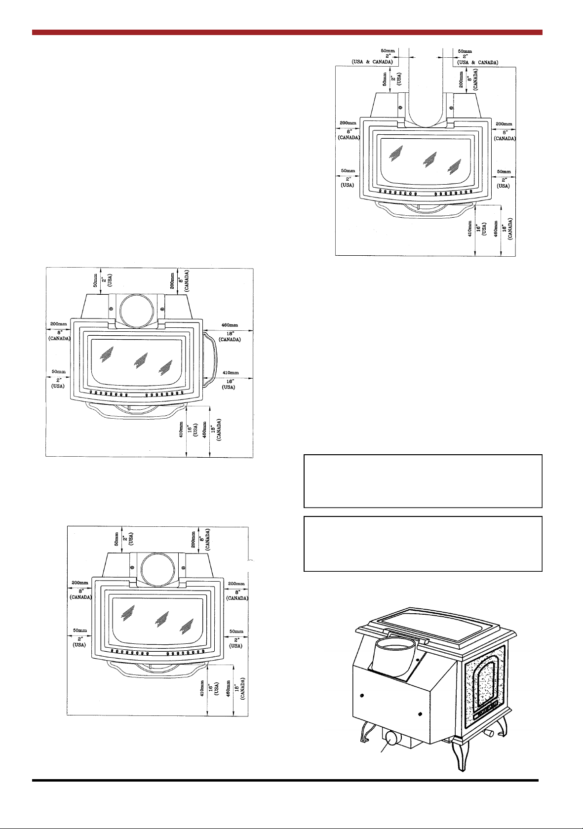
STOVE SPECIFICATIONS
The overall dimensions of the stove are as follows:
LENGTH: 614mm (24.17”)
WIDTH: 650mm (25.58”)
HEIGHT: 669mm (26
FLUE SPIGOT DIAMETER: 152mm (6”)
O.S.A. HOOK UP DIAMETER: 102mm (4”)
HOT PLATE DIMENSIONS: 444mm x 217mm
(17.48” x 8.94”)
HEIGHT TO CENTRE OF FLUE ON REAR
OUTLET CONFIGURATION: 565mm (22.24”)
HEIGHT TO CENTRE OF OSA HOOK UP
CONNECTOR: 109mm (4.25”)
WEIGHT: 432 lbs (196 kgs)
(See Fig.’s 1 through to 4)
1
/3”)
CAUTION:
THIS APPLIANCE IS HOT WHILE IN OPERATION AND RETAINS ITS HEAT FOR A LONG
PERIOD OF TIME AFTER USE. CHILDREN,
AGED OR INFIRM PERSONS SHOULD BE
SUPERVISED AT ALL TIMES AND SHOULD
NOT BE ALLOWED TO TOUCH THE HOT
WORKING SURFACES WHILE IN USE OR
UNTIL THE APPLIANCE HAS THOROUGHLY
COOLED.
DO NOT USE CHEMICALS OR FLUIDS TO
START OR “FRESHEN UP” THE FIRE.
DO NOT BURN GARBAGE OR FLAMMABLE
FLUIDS OR MANUFACTURED LOGS.
1
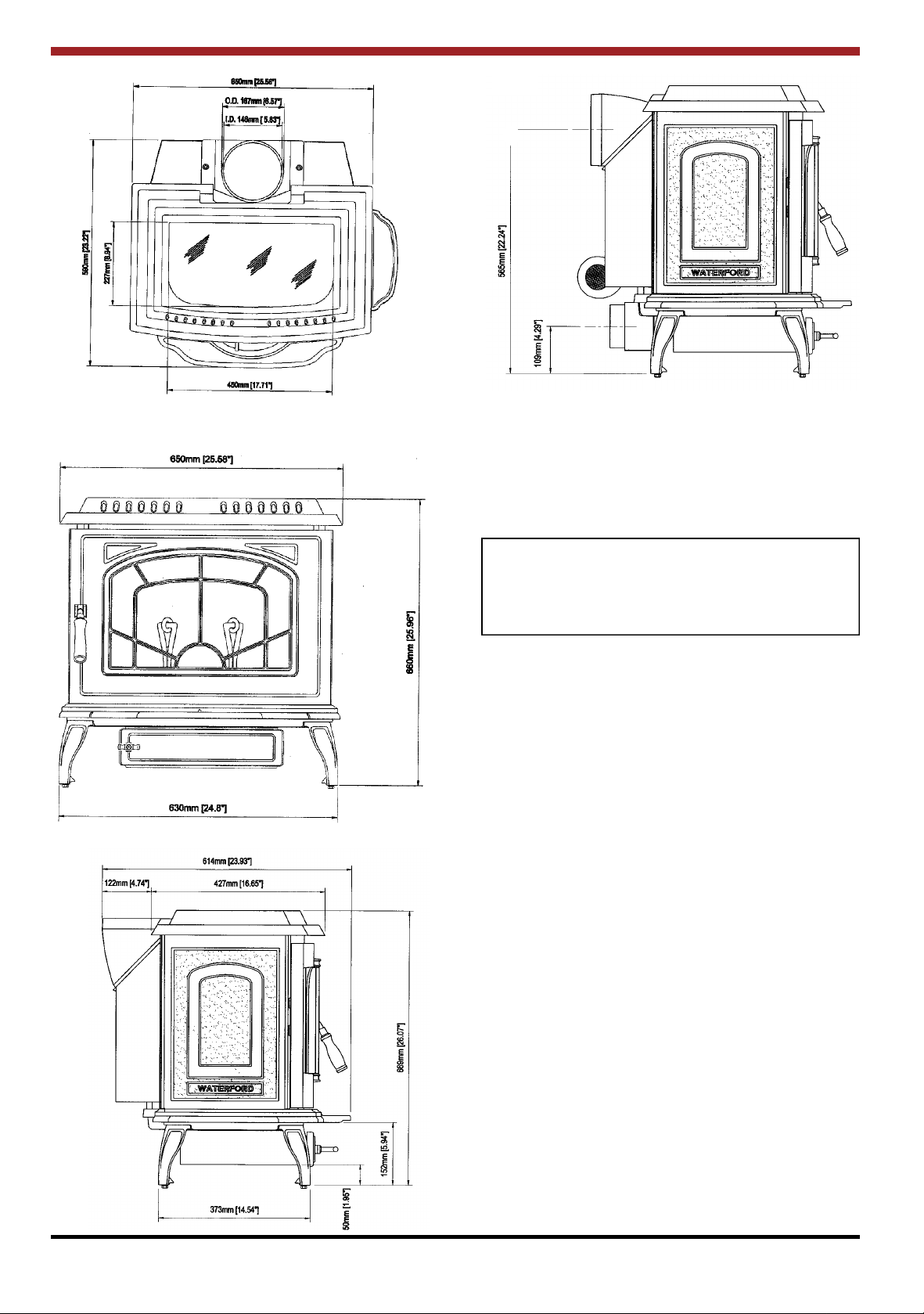
Fig.1
Fig.4
Fig.2
Fig.3
ASHLING WOODBURNING STOVE
INSTALLATION AND OPERATING
INSTRUCTIONS
GENERAL
The complete installation must be done in accordance with current Standards and Local Codes. It
should be noted that the requirements and these
publications may be superseded during the life of
this manual.
The Ashling Wood Stove has been independently
tested by Warnock Hersey in accordance with UL
1482 and ULC S627.
When installing, operating and maintaining your
Ashling Stove respect basic standards of fire safety. Read these instructions carefully before commencing the installation. Failure to do so may
result in damage to persons and property. Consult
your local Municipal office and your insurance representative to determine what regulations are in
force. Save these instructions for further reference.
PRE-INSTALLATION ASSEMBLY
(a) After removing the stove from its packing,
open the ash door (item 18 in exploded
view) and remove the contents.
(b) Open the front door (item 5) and remove
the contents of the firebox, leaving the
bricks in place.
(c) Remove the front ashtray (item 23) from
the rear of the stove if you have not already
done so. Remove the loose fitting hob and
place on a non-abrasive surface.
2
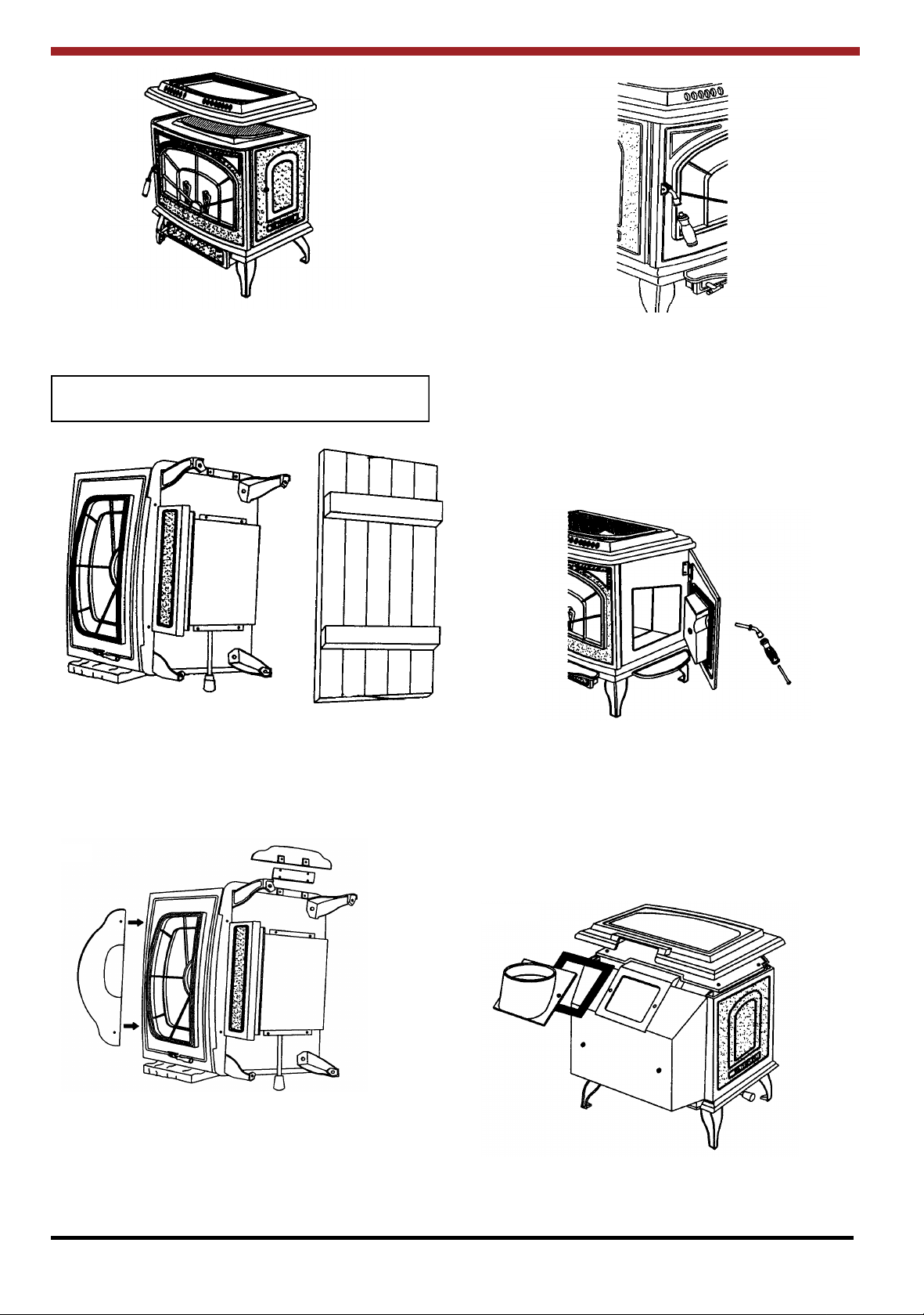
Fig.5
Fig.8
(d) Place the plastic packing on the ground at
the left hand side of the stove.
NOTE: As the stove is very heavy take care when
laying the stove on its side on top of the packing.
Fig.6
(e) Remove the two
1
/4” (6mm) x 1/2” (12mm)
hex head bolts from the base (item 3) and
fit the front ashtray (item 23) using the two
hex head bolts. Stand the stove upright
taking care not to strain the leg bolts.
Fig.7
(g) If the side load door (item 7) is to be used,
fit the side ashtray (item 24) using the side
ashtray fixing plate (item 56) and screw
together using four
1
/4” (6mm) x 1/2”
(12mm) hex head bolts provided. Take out
the chrome locking bolt and fit door latch
(item 52), the side door handle axle (item
51) and the side door handle (item 50).
Fig.9
This stove can be connected to either a top or rear
exit by simply reversing the orientation of the flue
spigot (item 17) on the flue spigot flange.
For either the top or the rear exit option place the
ceramic gasket onto the flue spigot flange - located at the top of the back plate.
(f) Fit the front door handle (item 54) using
the front door handle screw (item 67) to
the front door (item 5).
Fig.10
3
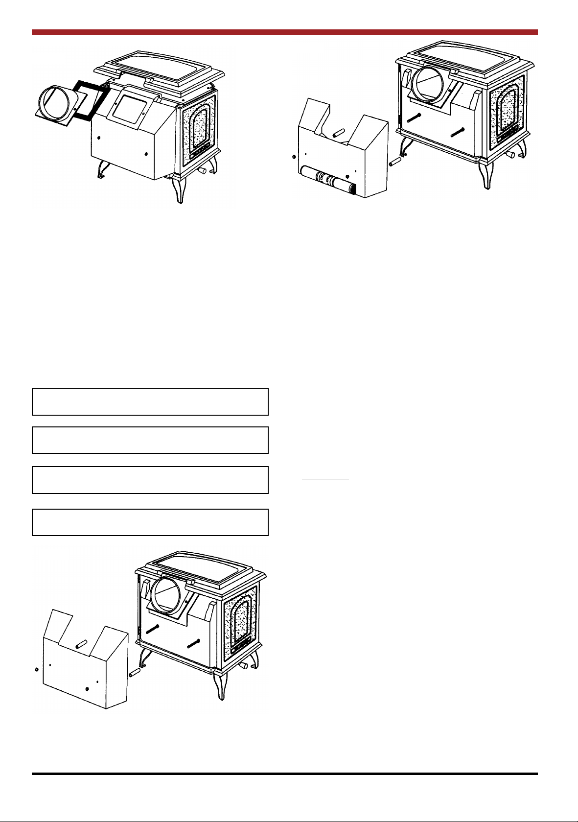
Fig.11
Fig.13
BLOWER
An Optional Blower is available for the Waterford
Ashling. The blower is factory assembled, wired
and ready for attachment to the stove.
This unit must be connected to a grounded, standard 110 volts, 60 Hz electrical outlet. Never route
the power cord under or in front of the unit.
Do not under any circumstances, cut or remove
the grounding prong from the power cord. Do not
use an adaptor plug.
NOTE: For more detailed information see instructions included with the Optional Blower.
CAUTION: Moving parts may cause injury. Do not
operate unit with blower housing removed.
D A N G E R: Risk of electric shock. Disconnect
power before servicing unit.
HOT PARTS: Do not operate unit with blower
housing removed.
Fig.12
FLOOR PROTECTION
When installing this heater on a combustible floor,
a floor protector, is required. The floor protector is
to consist of a layer of non-combustible material
and cover the area under the heater and extend to
the sides and rear. It must also extend beneath a
horizontal chimney connector and 2” (50mm)
beyond each side. The area 16” (410mm) in front
of the fuel door(s) must have a thermal resistance
R value of 1.2.
Note: For use in Canada, the floor protector must
extend to at least 18” (460mm) in front of the fuel
door(s) and to at least 8” (200mm) from the sides
and rear of the stove.
If alternative materials are used the following
equations and information shall be used to calculate the alternative material thickness required:
Example:
The specified floor protector should be
3
/4” (18mm)
thick material with a K - factor of 0.84.
The proposed alternative is 4” (100mm) brick with
a C-factor of 1.25 over
1
/8” (3mm) mineral board
with a K-factor of 0.29.
Step (a): Use formula above to convert
specification to R-value.
R = 1/k x T = 1/0.84 x .75 = 0.893.
Step (b): Calculate R of proposed system.
4” brick of C = 1.25, therefore
Rbrick = 1/C = 1/1.25 = 0.80
1
/8” mineral board of k = 0.29,
therefore Rmin.bd. = 1/0.29 x 0.125
= 0.431.
Total R = Rbrick + Rmineral board =
0.8 ÷ 0.431 = 1.231.
Step (c): Compare proposed system R of
1.231 to specified R of 0.893.
Since proposed system R is
greater than required, the system is
acceptable.
4
Definitions:
Thermal Conductance =
C = Btu = W
Thermal Conductivity =
k = (Btu)(inch) = W = Btu
Thermal Resistance =
R = (ft2)(hr)(oF) = (m2)(K)
Fig.14
Fig.16
(hr)(ft2)(oF) (m2)(K)
(hr)(ft3)(oF) (m)(K) (hr)(ft)(oF)
Btu W
LOCATION
There are several conditions to be considered
when selecting a location for your Ashling Wood
Stove.
(a) Distance from a safe chimney.
(b) Position within the area to be heated - cen-
tral locations are usually best.
(c) Allowances for proper clearances to
combustibles.
(d) Obstruction in the ceiling, upper floor or
roof, for example, ducting, plumbing, electrical fittings and wiring, overhead fixed furnishings etc.
** If the side door is to be used the floor protector
must extend at least 16” from this side.
Fig.15
WARNING:
DO NOT OBSTRUCT FREE AIR SUPPLY TO
THE AIR INLET DUCT LOCATED AT THE BACK
OF THE STOVE.
IMPORTANT: DO NOT CONNECT TO OR USE
IN CONJUNCTION WITH ANY AIR DISTRIBUTION DUCT WORK UNLESS SPECIFICALLY
APPROVED FOR SUCH INSTALLATIONS.
OUTSIDE AIR CONNECTION
Fig.17
Air Inlet Duct
5
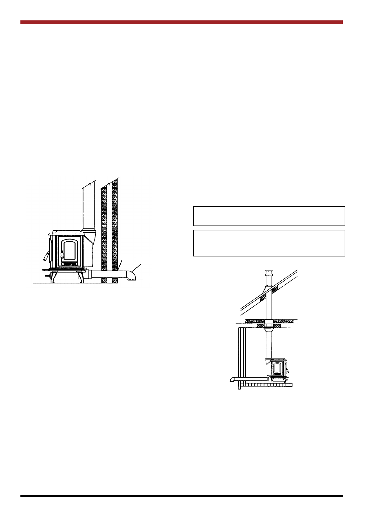
If desired, the air for combustion may be drawn
directly from the outside of the house, as detailed
below. It is not obligatory to do this, but it may help
combustion in small or poorly ventilated house.
Connect a 4” (100mm) diameter stainless steel, or
other non-combustible corrosion resistant material, to the O.S.A hook-up box (item 76). In order to
do this the O.S.A. hook-up box (item 76) must be
connected to the base (item 2) using
1
/4” x 2 1/4”
hex head bolts.
Run the pipe (up to 54” (1370mm) long) to the out-
side avoiding sharp bends and joints within cavity
walls. Turn the end down and fit corrosion resistant mesh to prevent the entry of leaves and
rodents. (See Fig.18). Seal the penetration of the
outside wall with silicon.
Fig.18
6. The chimney shall be attached directly to
the room heater and shall extend at least
3ft. (914mm) above the part of the roof
through which it passes. The top of the
chimney should project at least 2ft.
(610mm) above the highest elevation of
any part of the Mobile Home within 10ft.
(3048mm) of the chimney.
7. The chimney system shall comply with
Local Requirements (see page 7).
8. Any openings in a chimney guard where
required must not permit the entrance of
3
/4” (19mm) diameter rod.
9. CAUTION: THE STRUCTURAL INTEGRITY OF THE MOBILE HOME ROOF,
FLOOR WALLS AND CEILING MUST BE
MAINTAINED.
10. Check any other local building code as
other local codes may apply.
11. WARNING: DO NOT INSTALL IN A
SLEEPING ROOM OF A MOBILE HOME.
CAUTION: Do not obstruct combustion air
opening.
Seal
Air Duct
Wire Mesh
MOBILE HOME INSTALLATION
In addition to standard installation instructions the
following requirements are mandatory for installation in a mobile home.
1. The stove must be permanently bolted to
the floor of the Mobile Home using the floor
screws provided.
2. The stove must have a permanent outside
air source for combustion.
3. The stove must be electrically grounded to
the steel chassis of the Mobile Home.
4. A listed chimney system, roof thimble, spark
arrestor and roof flashing kit suitable for use in
Mobile Homes must be used.
5. If the chimney exits the Mobile Home at a
location other than through the roof, and
exits at a point 7ft. (2130mm) or less above
the ground level on which the Mobile Home
is positioned a guard or method of enclosing
the chimney shall be fitted at the point of exit
for a height up to 7ft. (2130mm)
Note: Listed factory built chimney connectors
including elbows are acceptable for use in Mobile
Home Installations.
Fig.19
6
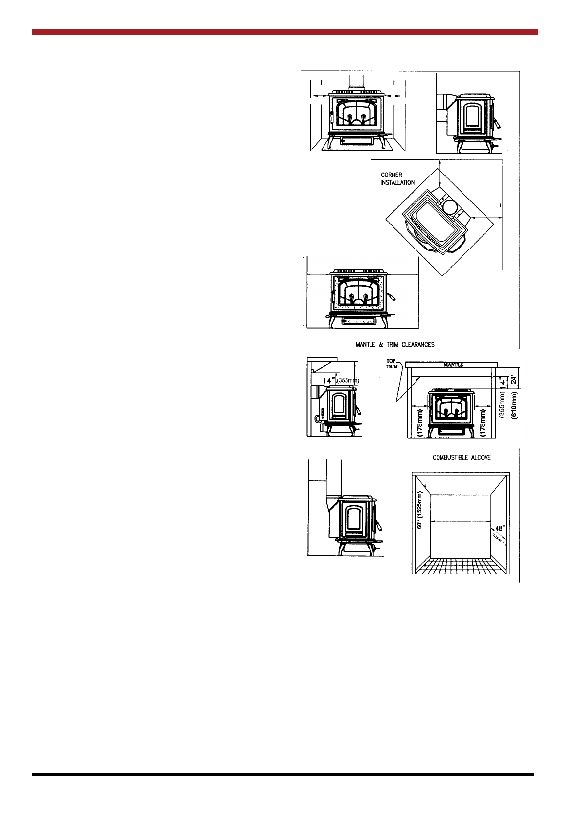
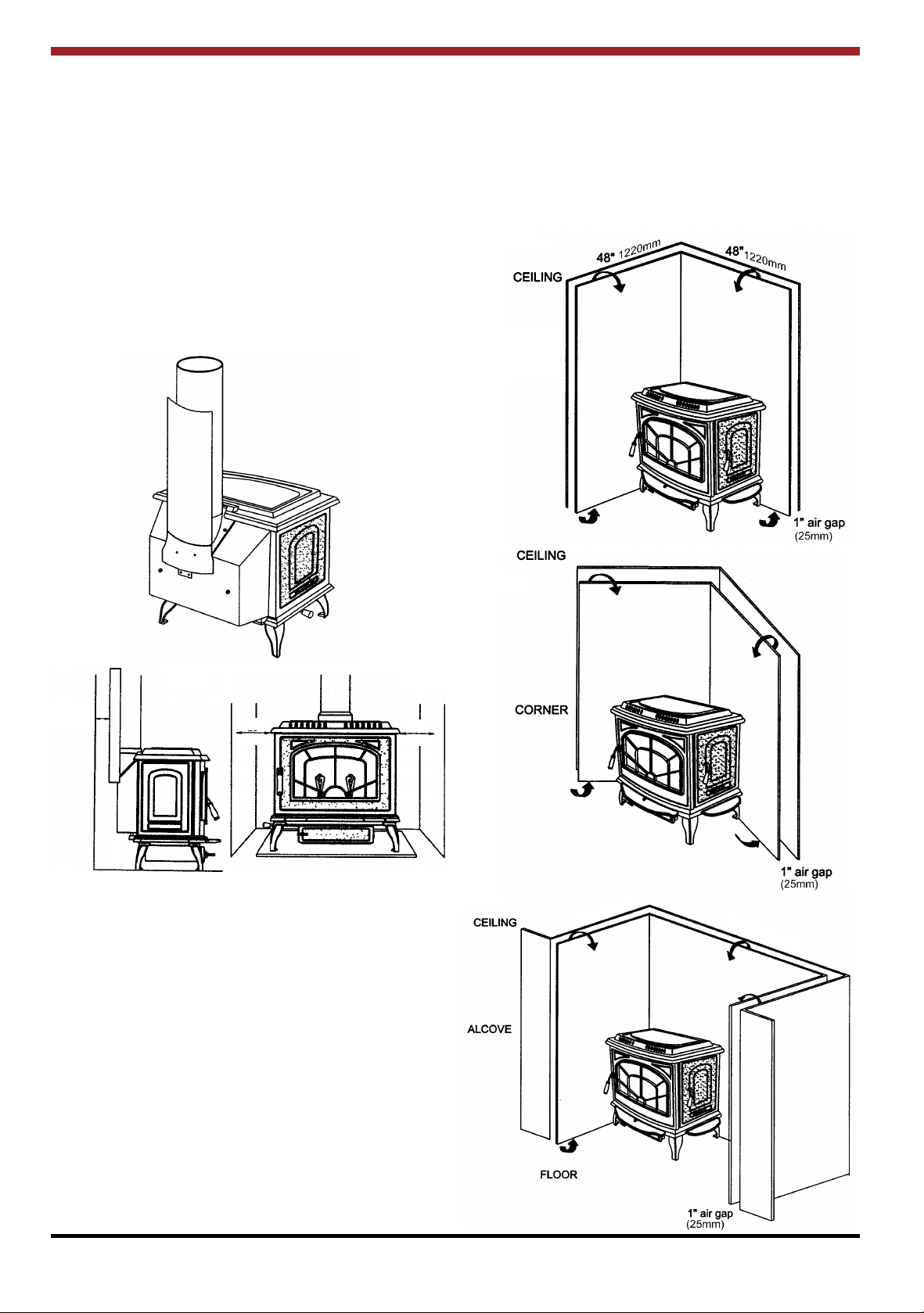
MINIMUM CLEARANCES TO COMBUSTIBLE
MATERIALS
Fig.20
Without Side Load Door
Fig.21
From the front of the stove 36” (915mm)
From the side of the stove 16” (406mm)
From wall when installed at 45
o
across a corner 12” (305mm)
From back of stove 12” (305mm)
From back of stove horizontal
installation only 6” (150mm)
If the side door is to be used the clearance at
this side must be increased to 36” (915mm)
Mantle clearance 24” (610mm)
Top Trim Clearance 14” (335mm)
Side Trim Clearance 7” (178mm)
Vertical single wall flue pipe 12” (305mm)
This stove may be installed in an alcove measuring
at least 60” (1525mm) high x 58” (1475mm) wide
and no greater than 48” (1220mm) deep (See Fig.
22)
16” 16”
(405mm) (405mm)
Fig.22
Fig.23
With Side Load Door
(406mm)
Fig.24
36”16”
(915mm)
150mm
6”
12” (305mm)
Fig.25
(305mm)
12”
Fig.26
12”
24”
(305mm)
610mm
7” 7”
Fig.27
58”
(1475mm)
7
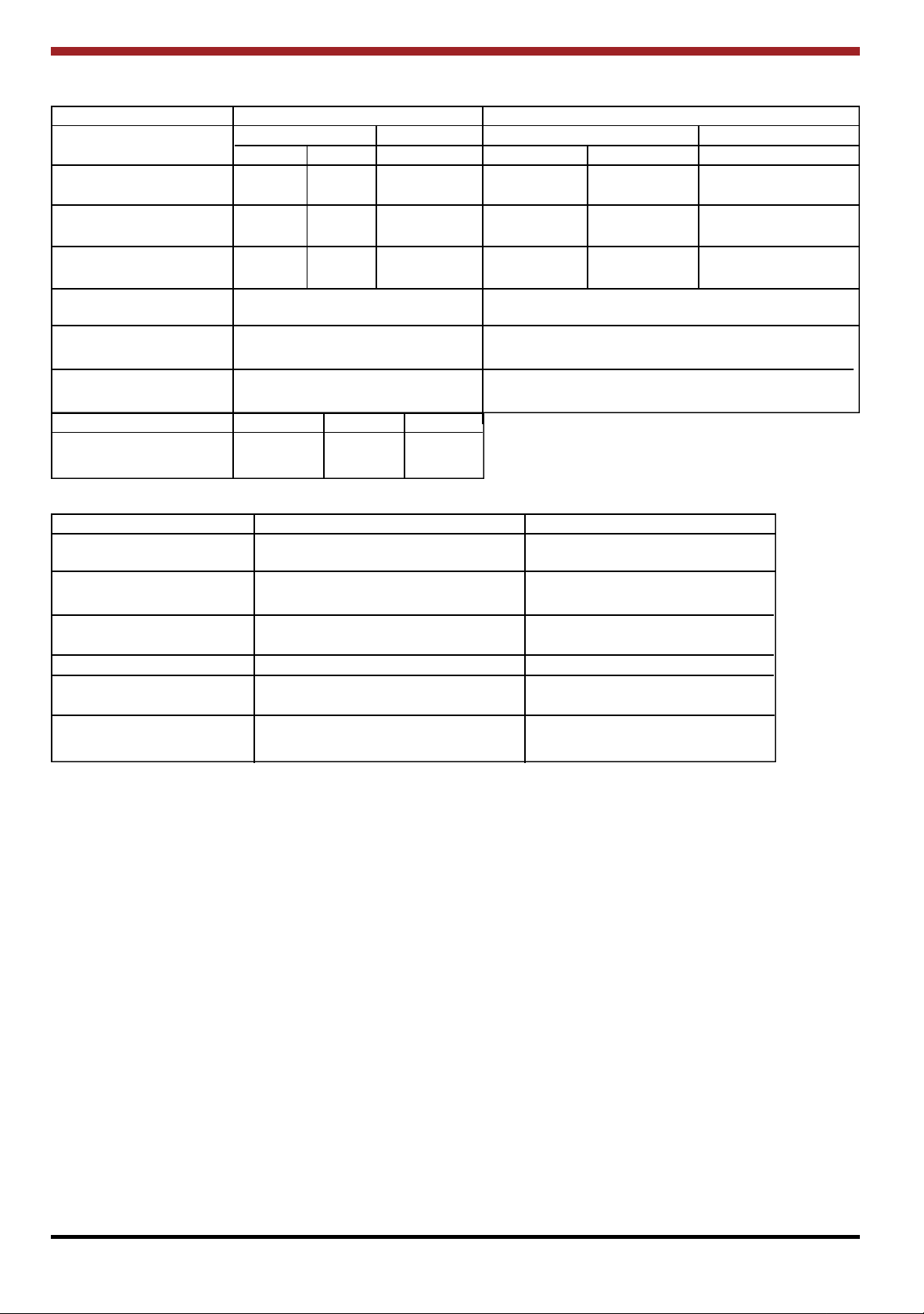
ADDITIONAL CLEARANCES TO COMBUSTIBLES
Appliance Clearances Unprotected Surfaces Protected Surfaces (NFPA - 211)
Parallel Corner Parallel Corner
Side Rear Side Rear
No Heat Shields 16-in 12-in 12-in 7-in 6-in 6-in
405-mm 305-mm 305-mm 180-mm 150-mm 150-mm
Flue Collar and 14-in 6-in 10-in 7-in 6-in 6-in
Connector Shield 355-mm 150-mm 255-mm 180-mm 150-mm 150-mm
Double Wall Connector 14-in 6-in 10-in 7-in 6-in 6-in
355-mm 150-mm 255-mm 180-mm 150-mm 150-mm
Minimum alcove 58-in 40-in
Width 1475-mm 1015-mm
Maximum alcove 48-in 48-in
Width 1220-mm 1220-mm
Alcove Ceiling Above 34-in 12-in
Stove top 865-mm 305-mm
Hearth Mount Side Trim Top Trim Mantle
7-in 14-in 24-in
180-mm 355-mm 610-mm
Chimney Connector Unprotected Surfaces (vert) Protected Surfaces (vert).
No heat shields 12-in 6-in
305-mm 150-mm
Using Connector Shield 6-in 6-in
150-mm 150-mm
Double Wall Connector 6-in 6-in
150-mm 150-mm
Unprotected Surfaces (horiz.) Protected Surfaces (horiz.)
Single Wall Connector 18-in 12-in
460-mm 305-mm
Double Wall Connector 6-in 6-in
150-mm 150-mm
FLOORING REQUIREMENTS
The unit must be placed on non-combustible material extending 2-in (50mm) beyond each side, 2-in (50mm)
beyond the rear, and 2-in (50mm) beyond each side of the chimney connector. If the optional side fuelling
door is used, the floor protection must extend 16-in (410mm) beyond the door. Combustible flooring 16-in
(410mm) beyond the front and 8-in (200mm) beyond each side of the front fuel opening must be protected
by either a listed non-combustible insulative floor protector or a field installed non-combustible insulative floor
protection with an R value of at least 1.2.
For use in Canada, the non-combustible floor protection must be extended to 18-in (460mm) beyond the fire
door(s) and 8-in (200mm) beyond the sides and rear of the stove.
8

9
REDUCED CLEARANCES
Under certain conditions the minimum clearances
may be reduced by means of:
(a) The use of Listed pipe shields, installed in
accordance with the manufacturer’s
instructions.
(b) Shields constructed in accordance with NFPA
211 (USA), CAN3-B365 (CANADA) installation
codes.
(c) When listed pipe shields are used - top exit
option only - the clearances may be reduced
to 6” (150mm) from the pipe shield and 8”
(225mm) from stove back.
Fig.28
All clearances must be measured from the outer
surface of the combustible material to the nearest
point on the surface of the stove disregarding any
intervening protection applied to the combustible
material.
Listed Heat Shields must be installed in accordance with the manufacturer’s instructions.
Fig.31
Parallel side
and back
wall to stove
150mm
Fig.29
6”
7”
178mm
Fig.30
7”
178mm
DOUBLE WALL CONNECTIONS
Double wall chimney connectors may be substituted for the shielded pipe provided it is UL/ULC listed for a 9” (225mm) clearance or less.
WALL HEAT SHIELDS/PROTECTORS
Fig.32
Fig.33
Shields intended to reduce clearance to combustibles must be installed in accordance with the
appropriate codes.
To allow for the circulation of cooling air leave a
space of at least 1” (25mm) between the wall and
the shield. Leave a gap of at least 1” (25mm)
between the top of the shield and the ceiling and
between the bottom of the shield and the floor.
10

CHIMNEY
CHIMNEY CONNECTOR
The Ashling is a radiant room heater and must be
connected to a chimney of the proper size and
type capable of providing an adequate continuous
draught of 0.04” wg - 0.06” wg. A 6” diameter
Factory Built Chimney is ideal. Connection to a
larger size may result in somewhat less draught.
DO NOT CONNECT TO A CHIMNEY SERVING
ANOTHER APPLIANCE.
Minimum chimney height is 15 feet from floor on
which stove is installed. An existing masonry
chimney should be inspected and, if necessary,
repaired by a competent mason or relined using an
approved relining system. The stove must be connected to a chimney with a continuous draught of
0.04” wg - 0.06”wg. Poor draught conditions will
result in poor performance.
Excessive draught can cause overfiring. If any
components start to glow red, the stove is operating in an overfiring condition and the primary air
needs to be reduced to eliminate the overfiring as
overfiring voids the warranty. Warped components
are indicative of overfiring and will not be covered
under warranty.
The chimney connector (smoke pipe) is used to
connect the Ashling Stove to the chimney
described above. The chimney connector must be
made of Corrosion Resistant Steel, 24 gauge or
heavier (black or equivalently treated steel). Be
sure to fasten the chimney connectors together
and also to the flue outlet of the stove through the
two holes provided. Use at least two screws for
each joint/connection. Be sure that the joints are
tight and fully sealed.
A chimney connector shall not pass through an
attic or roof space, closet or similar concealed
space, floor or ceiling.
Where passage through a wall or partition of combustible construction is desired, the installation
shall conform to NFPA 211 or CAN/CSA - B365.
The connector should maintain a pitch or rise of at
1
least
/4” per foot from the stove to the chimney. It
should be installed so as to avoid sharp turns or
other combustion features that would create
excessive resistance to the flow of flue gases. It
should be securely supported. The entire length of
a connector should be readily accessible for
inspection, cleaning and replacement.
The use of a surface mounted thermometer is
recommended to monitor the hotplate centre temperature. If the hotplate exceeds 900oF the stove
is overfiring.
Note: The fitting of a flue damper can help reduce
the draught in chimneys with excessive draught.
CHIMNEY TYPES: USA ONLY
The stove must be connected to a UL 103 Listed
HT Type Factory Built Chimney for Residential
Type and Building Heating Appliances, installed in
accordance with the manufacturer’s instructions or
a masonry chimney constructed in accordance
with NFPA 211 Chimney Vents and Solid Fuel
Burning Appliances.
CHIMNEY TYPES: CANADA ONLY
The stove must be connected to an Underwriters
Laboratories of Canada Labelled factory built
650oC chimney, installed in accordance with the
manufacturer’s instructions or to a lined masonry
chimney acceptable to the authority having jurisdiction.
CONNECTING TO MASONRY CHIMNEY
The connector may pass through walls or partitions constructed of combustible material to a
masonry chimney provided the connector system
selected is installed in accordance with the proper
clearances and conditions. The thimble (breach
pipe) must extend to, but not beyond the inner face
of the masonry chimney liner and be firmly
cemented in place. A fire clay liner (ASTM C315
or equivalent) or stainless steel, at least 24 gauge
may be used.
The following methods may be employed:
Method 1:
Minimum 3
1
/2” (90mm) thick brick masonry wall
framed into combustible wall with a min. of 12”
(300mm) brick separation from clay liner to combustibles.
Method 2:
Solid insulated Listed factory-built chimney length
of the same inside diameter as the chimney connector and having 1” (25mm) or more of insulation
with a min. 9” (228mm) air space between the
outer wall of the chimney length and combustibles.
The inner end of the chimney length shall be flush
11
 Loading...