


Installation Instructions
16K SidewinderTM
DEALER/INSTALLER:
(1) Provide this Manual to end user
Part Numbers:
SW16K, ST100-SW16K. ST200-SW16K, ST300-SW16K, ST400-SW16K, ST500SW16K, ST100-SW16KPOE*, ST200SW16KPOE*, ST400-SW16KPOE*
* = Pre-Assembled
END USER:
(1)Read and follow this Manual every time you use Sidewinder.
(2)Save this Manual for Future Reference.
PIN BOX SHOWN ASSEMBLED
(3) Pass on copies of Manual to any other users or owner.
|
Equipment Required: |
|
|
|
|
|
|
|||
|
|
|
|
Do Not Exceed Lower of Towing Vehicle Manufacturer’s Rating, |
|
|
||||
|
Fastener Kit: ST100F |
|
Trailer Manufacturer’s Rating or |
|
|
|||||
|
|
|
|
|
|
|
|
|||
|
|
|
|
|
|
|
|
|
||
|
Wrenches: 15/16”, 1 1/8” |
|
Max Gross |
|
Max Pin |
|
|
|||
|
|
|
|
|
|
|
|
|||
|
Drill Bits: Not Required |
|
Trailer WT (LB) |
|
WT (LB) |
|
|
|||
|
White Lithium Grease, Torque Wrench |
|
|
|
|
|
|
|||
|
|
16,000 LB |
|
3,200 LB |
|
|
||||
|
|
|
|
|
|
|
|
|
|
|
|
|
|
|
|
|
|
|
|
|
|
|
1 |
Qty. (1) |
Turret (ST100, ST200, ST300, ST400, or ST500) |
|
7 |
|
|
|||
|
|
|
|
|
|
|
|
|
||
|
|
|
|
|
|
|
|
|
|
|
|
2 |
Qty. (1) |
Wear Plate |
|
|
5 |
|
|
||
|
|
|
|
|
|
|
|
|
||
|
3 |
Qty. (1) |
16K SidewinderTM |
|
|
|
|
|||
|
|
|
|
|
|
|
||||
|
|
|
|
|
|
1 |
|
|
|
|
|
4 |
Qty. (1) |
Universal Wedge* |
|
|
|
||||
|
|
|
|
|
|
|
||||
|
|
|
|
|
|
|
|
|
|
|
|
5 |
Qty. (6) |
5/8” Lock Washer |
|
|
|
|
|
|
|
|
|
|
|
|
|
|
|
|
|
|
|
6 |
Qty. (2) |
Wedge Bolt, 5/8”-11 X 1 3/4” Grade 5 Hex Bolt |
|
|
|
|
|
||
|
|
|
|
|
|
|
|
|
|
|
|
7 |
Qty. (4) |
Cap Bolt, 5/8” – 11 X 2” Grade 8 Hex Bolt |
|
|
|
|
|
|
|
|
|
|
|
|
|
|
|
|
|
|
|
8 |
Qty. (2) |
3/4” – 10 Hex Nut** |
|
|
|
|
|
|
|
|
|
|
|
|
|
|
|
|
|
|
|
9 |
Qty. (2) |
3/4” Lock Washer** |
|
|
2 |
|
|
||
|
|
|
|
|
|
|
|
|
||
|
|
|
|
|
|
|
|
|
|
|
|
|
Qty. (4) |
3/4“ Flat Washer** |
|
|
|
|
|
|
|
|
|
Qty. (1) |
Outer Cap |
|
|
|
|
|
|
|
|
|
|
|
|
|
|
|
|
|
|
|
|
Qty. (1) |
Upper Wear Disc |
|
3 |
|
|
|
|
|
|
|
Qty. (1) |
Pivot Bushing |
|
|
|
|
|
|
|
|
|
Qty. (2) |
Convertible Bolts, 3/4” – 10 X 5 ½” ** |
|
|
|
|
|
|
|
|
|
|
|
|
|
|
|
|
|
|
|
*Custom Wedges are available for most fifth wheel hitch applications, to order a custom |
|
|
|
|
|||||
|
wedge |
kit, see your RV Dealer or contact CPP Technical Service: 1-888-521-0510. |
|
|
|
|
||||
|
**Included on OEM installed units only. |
|
|
|
|
|
|
|||
INDEX |
|
|
|
|
|
|
|
|
|
|
1. |
GUIDELINES FOR MATCHING TOW VEHICLE AND TRAILER |
P. 2-3 |
|
|
|
|
||||
2. |
ASSEMBLY INSTRUCTIONS |
P. 4-6 |
|
|
|
|
||||
3. |
OPERATION INSTRUCTIONS |
P. 6-10 |
|
|
|
|
||||
4. |
WEDGE ADJUSTMENT/SELECTION |
P. 7-8 |
|
|
|
|
||||
5. |
HITCHING PROCEDURE, |
P. 9-11 |
5 |
|
|
|||||
|
PULL TEST, UNHITCHING PROCEDURE |
|
|
|
Figure 1 |
6 |
||||
|
|
|
|
|
||||||
6. |
BEFORE EACH TRIP |
P. 11 |
|
|
|
|
||||
7. |
MAINTENANCE |
|
|
P. 11 |
|
|
|
|
||
7. |
NOTES |
|
|
P. 12 |
|
|
|
|
||
8. |
5 YEAR LIMITED WARRANTY |
P. 12 |
|
|
|
|
||||
8**
9**
**
****
4*
WARNING:
Failure to follow all of these instructions may result in death or serious injury!
z 2009 Cequent Performance Products |
Sheet 1 of 12 |
SW16KN |
02-11-09 |
Rev. A |
|
|
|
|
|
Form: F205 Rev A 5-6-05
Installation Instructions
16K SidewinderTM
GUIDELINES FOR MATCHING TOW VEHICLE AND TRAILER
WARNING:
Failure to check and follow tow ratings could result in tow vehicle damage or truck and trailer separation while towing.
•Trailer and its contents together must not exceed truck, hitch and/or trailer tow ratings.
•Towing vehicle must have a manufacturer’s rated towing capacity equal to or greater than the gross trailer weight (dry weight of the trailer plus payload of the trailer). (See Fig. 2)
•Gross weight of trailer must not exceed 16,000 pounds for this product.
•King pin weight must not exceed 3,200 pounds (See Fig. 3). If in doubt have king pin weight measured by qualified facility.
1. Check Tow Ratings:
Vehicle Tow Rating: ________________.
16,000 lbs.
16K Sidewinder Pin Box Rating:________________.
FACTORY TRAILER + FULL WATER TANKS + CARGO, ETC. = GROSS TRAILER WEIGHT
Gross Trailer Weight (Figure 2):________________.
*Trailer weight should be the lowest of these recorded ratings for safe towing conditions.
Figure 2
2. The Sidewinder™ pin box is designed for a maximum of 20% Gross Trailer Weight on the pin (Pin Weight). See Fig. 3
Figure 3
20% MAX. GROSS |
|
TRAILER WEIGHT |
80% GROSS |
|
|
(PIN WEIGHT) |
TRAILER WEIGHT |
|
|
|
|
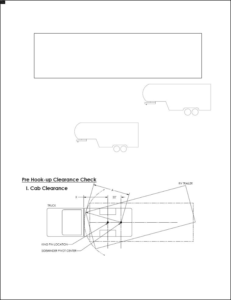
3. Trucks & RV Trailers come in many different configurations; Installations of 5th Wheel Hitches often vary by installer, it is necessary to check the clearances in figures 4 & 5 before hook up and towing with Sidewinder™.
Figure 4
Measure Distance “A”: From Center of Sidewinder™ pivot to farthest point on coach front cap.
Measure Distance “X”: From King Pin to the rear of the truck cab.
If Distance “X” + 24” is Greater Than Distance “A” Towing up to 90º or More is possible.
z 2009 Cequent Performance Products |
Sheet 2 of 12 |
SW16KIN |
02-11-09 |
Rev. A |
|
|
|
|
|
Form: F205 Rev A 5-6-05

Installation Instructions
16K SidewinderTM
GUIDELINES FOR MATCHING TOW VEHICLE AND TRAILER – CON’T
Figure 5
CAUTION: A minimum clearance between the bumper and trailer (Measured at the same height) of 2 ft. is recommended. Due to Vehicle and RV Trailer variations; it is necessary to check this clearance. If the clearance is less than the minimum, this can be done after installation by making a slow turn, in a controlled driving environment (i.e. closed parking lot, grass field, etc.) with the aid of an observer to watch for interference.
4.The Height of the hitch and pin box should be adjusted so the trailer is approximately level as it is towed. Allow approximately 6 in. clearance between the top of the bed and the underside of the front of the trailer for pitch and yaw of the trailer (See Figure 6). For off-road use allow more clearance between pickup walls and trailer.
Figure 6
CAUTION:
The Measurements in figures 4, 5 & 6 are guidelines, If your measurements are close to these numbers, re-check clearances. If vehicle and/or trailer has any added bed vanity accessories (i.e. fairings, air dams, ground effects, bed rails, etc.) additional dimensioning and clearance checks have to be made. CPP is not responsible for damage incurred due to disregarding these clearance checks.
 WARNING:
•Cequent Performance Products does not recommend the use of a Sidewinder™ or 5th Airborne Sidewinder™ with the Curt Q5 Fifth Wheel Hitch.
•B&W 5th Wheel Hitches may only be used with a Sidewinder™ or 5th Airborne SidewinderTM if hardware is added to the bed of the truck and the 5th Wheel Hitch which may void the B&W warranty.
•The Reese Trail Boss 5th Wheel Head, part number 30050 is not compatible with any SidewinderTM products.
•Do not use a lube plate with Sidewinder™ & 5th Airborne Sidewinder™
WARNING:
Avoid putting any part of your body under the trailer or between the truck and trailer. Unexpected or accidental movement of the truck or the trailer can cause serious injury or death
•If you must place any part of your body under the trailer or between the truck and trailer you MUST perform ALL of the following steps:
•Check that the truck transmission is in park
•Check that the emergency brake is set
•Block in front of and behind all trailer tires
•Check that the trailer landing gear are resting on firm ground
z 2009 Cequent Performance Products |
Sheet 3 of 12 |
SW16KIN |
02-11-09 |
Rev. A |
|
|
|
|
|
Form: F205 Rev A 5-6-05

Installation Instructions
16K SidewinderTM
ASSEMBLY INSTRUCTIONS – For Pre-Assembled OEM Models use this section as a point of reference.
1.Before removing the original pin box, take note of the number of bolts used attaching the existing pin box to the mounting wing set. Cequent Performance Products recommends using at least the same number of bolts upon installation as removed from the original pin box. (Figure 7)
Mounting Wing Set
Figure 7
2.Check all boxes for all components listed in figure 1.
3.Remove the existing pin box, taking care to remove any necessary wiring and/or break away switch if attached to the pin box. (If removed, the break away switch must be reinstalled after installation is complete)
4.Install the turret inside the mounting wings (Figure 8). Cequent Performance Products recommends replacing the mounting bolts, nuts, and lock washers with the same size & grade as the bolts removed from the original pin box.
Torque all bolts to the proper value listed in table 1. |
Bolt Diameter |
Torque |
|
|
|
|
|
|
1/2” Bolts |
GR5 |
90 ft-lbs |
|
|
|
|
|
5/8” Bolts |
GR5 |
150 ft-lbs |
|
|
|
|
|
3/4” Bolts |
GR5 |
275 ft-lbs |
|
|
|
|
Table 1
Lowest Point on Wings
Bottom of Turret
Figure 8
Note: Installing the front bolts first may ease alignment. |
Figure 9 |
CAUTION: The bottom of the turret must extend below the lowest point on the wings to allow the arm to clear during pivot. (Figure 9)
4.Install pivot bushing into the turret as shown in figure 10. Applying white lithium grease to the inner tube of the turret may ease assembly. Install wear plate onto sidewinder arm (Figure 11), be sure to place the chamfer facing down
(Figure 12). Apply white lithium grease to the surfaces shown in figure 13, be sure to coat the entire surface.
Apply White
Figure 11 |
Lithium Grease |
|
|
|
|
|
|
Figure 13 |
|
The chamfer on the wear plate Must face down as shown |
|
|
||
Figure 10 |
|
Figure 12 |
|
|
|
|
|
|
|
|
|
z 2009 Cequent Performance Products |
|
Sheet 4 of 12 |
SW16KIN |
02-11-09 |
Rev. A |
|
|
|
|
|
|
Form: F205 Rev A 5-6-05
 Loading...