


OPERATING INSTRUCTIONS
Elite Series
18K & 25K 5TH WHEEL HITCH
DEALER/INSTALLER:
(1)Provide this Manual to end user.
(2)Physically demonstrate hitching and unhitching procedures in this Manual to end user.
(3)Have end user demonstrate that he/she understands procedures.
HITCH HANDLE
END USER:
(1)Read and follow this Manual every time you use hitch.
(2)Save this Manual and Hitch Warning Hang Tag for future reference.
(3)Pass on copies of Manual and Hitch Warning Hang Tag to any other user or owner of hitch.
(4)Never remove hitch warning decals as shown in Figure 33 of this manual. If damaged, contact Cequent Performance Products (1-800-326-1090) for free replacement.
JAW TO HOLD
KING PIN
SKID PLATE
RAMP 
For Installation Assistance or Technical Help, Call 1-800-758-0869
30143IN – 12JAN10A |
PCN12853 |
2010 CEQUENT PERFORMANCE PRODUCTS, INC |
LITHO IN USA |
FOR KITS 30142 & 30143 |
|
|
|
 WARNING:
Failure to follow all of these instructions may result in death or serious injury
INDEX
1. BEFORE EACH TRIP |
P. 2 |
7. HITCHING PROCEDURE |
P. 13 |
2. LUBRICATION |
P. 3 |
8. PULL TEST |
P. 15 |
3. ASSEMBLY / ADJUSTMENT |
P. 4 |
9. UNHITCHING PROCEDURE |
P. 16 |
4. HITCH INSTALLATION |
P. 9 |
10. MAINTENCE |
P. 16 |
5. HITCH REMOVAL |
P. 9 |
11. PARTS EXPLOSION |
P.17 |
6. GUIDELINES FOR MATCHING HITCH |
P. 10 |
12. SEVEN YEAR LIMITED WARRENTY |
P.18 |
GUIDELINES FOR MATCHING HITCH TRUCK AND TRAILER
If preparing to tow a 5th wheel trailer which you have not rating checked previously, please consult (See Section 6) of Elite Series assembly instructions to verify proper ratings.
BEFORE EACH TRIP:
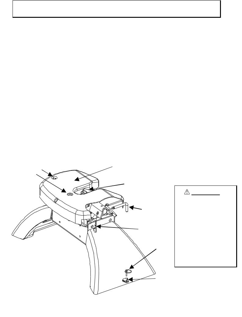
1.Lubricate skid plate surface of the hitch and pivot pin grease fitting (see Figure on cover of Manual) with automotive type chassis grease or use a plastic lube plate to provide a lubricated surface. Use lithium grease to lubricate pivot points of moving parts within the hitch.
2.Plastic lube plates (Towing Products No. 83001/40001) can be used to avoid messy grease. The plastic lube plate must not exceed 3/16 of an inch in thickness to ensure hitch will operate properly. Lube plates must be 12 inches in diameter or larger to properly distribute king pin weight.
3.Before each trip or maneuver, operate the handle and check that the jaw opens and closes freely.
4.See that all hitch pull pins (# 14, Figure 33) are in place and the spring retaining pins (#15, Figure 33) are installed (Figure 1). Note that hitch pull pins used with the Elite Series Hitch are 90 degree bent pins and if replacements are needed, please contact the factory. Check that all four anchor assembly handles are lynch pinned/locked through base arch shell.
Site Holes (2) |
Lube Skid Plate |
Grease Fitting |
(With No Lube Plate) |
|
|
|
Lube Jaw |
Pull Pin
Retaining
Clip
Lynch
Pin
Anchor Handles overlapped and through Arch Shell
Figure 1 : Pins and Clips (Skid Plate cut away view)
30143IN – 12JAN10A |
PCN12853 |
2010 CEQUENT PERFORMANCE PRODUCTS, INC |
LITHO IN USA |
2 |
FOR KITS 30142 & 30143 |
|
|
|
|

LUBRICATION:
1.Lube center section as shown in Figure 2 with lithium grease.
2.Lube pins (2) and slide bar opening as shown in Figure 3 with lithium grease prior to installation/operation.
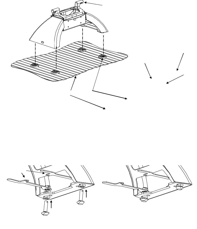
3.Lube feet with lithium grease for easier engagement as shown in Figure 4.
 •Lube 6 places
•Figure 2: Lubrication Points
•Lubricate Pin
•Slide Bar Opening
•Figure 3: Pin/Lube
Points (Bottom View)
•Lubricate Pin  •(Access through jaw opening)
•Figure 4: Lube Points
Lube Points 
Typical on both Arches
30143IN – 12JAN10A |
PCN12853 |
2010 CEQUENT PERFORMANCE PRODUCTS, INC |
LITHO IN USA |
3 |
FOR KITS 30142 & 30143 |
|
|
|
|

Elite Series Fifth Wheel Assembly / Adjustment
TOOLS
7/16”, 9/16” and 15/16" Socket & Open End Wrench 200 lb-ft Torque Wrench
1-1/2” Box End Wrench
1. |
Check box for all components listed in Figure 1 and become familiar with component terminology. Center section, Arches, |
|
and Anchor assemblies may be packed assembled. If already assembled start at Step 7. Use this section if you need to |
|
adjust your assembly in the future. |
2.Loosely assemble the four anchor bushings, less the anchor tee pins and handles, to the base arches using the 1” nuts (Figure 5). Loosely assemble the two base arches to the center section using 5/8-11 hex head bolts and lock washers (Figure 6).
NOTE A : Hole positions used in assembly will need to be chosen based on the head height measurements taken previously. Choose calculated height closest to one of the following height dimensions: 14-1/2”(top holes), 15-3/4”(2nd holes down), 17”(3rd holes down), 18-1/4”(bottom holes on 18K model only).
NOTE B : The fore/aft position of the head relative to the tow vehicle axle can be adjusted by 1-1/2” based on the position of the center section (Figure 6). Choose the position that most closely positions the king pin 2” ahead of tow vehicle axle center and allows for proper towing clearances. See note in figure 6.
NOTE C : Base arch with the larger label must be positioned on the Driver’s side of the vehicle.
Figure 5 :
Anchor Bushing Attachment
1” Jam Nut 
Anchor Bushing
5/8 Lock
Washer(4)
5/8-11 Grade 8
Bolt(4)
Note offset of center section Post toward the front of tow vehicle
Small Label
HITCH
HEIGHT
NOTE:
The model shown is the 18K Elite, the 25K Elite will only have three bolting locations. They both will come preassembled in the 15 ¾” location.
14-1/2”
15-3/4”
17” 18-1/4”
Center Section
Large Label
(Driver Side)
Figure 6 :
Arch and Center Assembly
Base Arch
30143IN – 12JAN10A |
PCN12853 |
2010 CEQUENT PERFORMANCE PRODUCTS, INC |
LITHO IN USA |
4 |
FOR KITS 30142 & 30143 |
|
|
|
|
3.Place assembly into mounting pucks which are installed in truck(see Elite Series Mounting Kit Instructions). (Figure 7). Be sure that base arches are contacting all pucks with bushings slid into puck slots.
4.Tighten 5/8 bolts in center section to 170 ft.lbs. using 15/16 socket. Snug tight(no vertical play in anchor bushing assembly) all (4) 1” jam nuts inside base arches using a 1-1/2” box end wrench, then tighten each jam nut another 1/4 turn for proper torque requirement. Note that the unit is not secured down and should be held while tightening hardware.
Ear
Base Arch
Anchor Bushing
1” Nut
Puck
Truck Bed
Figure 7: Placement in Mounting
Truck Bed
Base Arch contacts Puck and Bushing fits inside Puck
5.Lift unit out of pucks. There should be minimal resistance. If there is some resistance, or you can not drop the unit back into the pucks, the unit should be adjusted; loosen 1” nuts and Center Section bolts and repeat Steps 3 & 4.
6.Insert anchor tee pin through bushing from bottom of base arch and thread into appropriate handle (see Figures 8A and 8B). (With notch in nut facing up and handle pointing toward you, the locking hole is to the right for the left handle and to the left for the right handle.) Keeping the handle in the unlocked position thread the anchor tee pin into handle nut until there is metal to metal contact with the bushing. Back tee pin off until parallel with bushing (less than ½ rotation), then loosen 1 more full rotation for nominal clearance adjustment (see Figures 8C, 8D, and 8E). At this point the slot in the handle nut and the hole in the tee pin should be aligned and the lynch pin needs to be inserted and closed (see Figure 9).
Locking
Holes
8A) Insert |
|
|
|
|
Anchor Tee |
|
|
|
|
Pin through |
|
8B) Thread Tee Pin into handle nut until |
|
|
Bushing |
|
snug, with handle in open position. |
|
|
30143IN – 12JAN10A |
PCN12853 |
2010 CEQUENT PERFORMANCE PRODUCTS, INC |
LITHO IN USA |
5 |
FOR KITS 30142 & 30143 |
|
|
|
|

8C) The pin will snug up at an undetermined angle
8D) Loosen Tee Pin back to first parallel with bushing position(less than ½ rotation)
8E) Loosen Tee Pin 1 additional complete rotation for suggested adjustment.
Figure 8: Anchor Tee Pin and Handle Orientation (all shown in unlocked position)
|
|
|
|
|
|
9A) Hole in top of Tee Pin will |
9B) Lynch Pin inserts through |
9C) When inserted snap Lynch Pin |
align with Handle Nut groove |
grove and hole |
Ring down over Handle Nut |
Figure 9 : Inserting Lynch Pin
WARNING:
Failure to properly install handles could result in tow vehicle damage or truck and trailer separation.
7.Replace unit into pucks with all handles in unlocked position (see Figures 10A and 10B). Rotate handles into locked position. It is normal for some of the handles to have very little or no resistance; while others have a moderate amount of resistance when locking. Should a handle not be able to be locked by hand it needs to be adjusted, see Note D.
NOTE D: To adjust handle tension when locking first remove hitch from pucks. Next, while keeping the handle to tee pin orientation, remove the lynch pin. Rotate the tee pin counterclockwise ½ rotation, and replace lynch pin. Conversely, if there is too much clearance in the attachments when locked, the clearance can be removed by rotating the tee pin clockwise ½ rotation, and replacing the lynch pin.
8.Remove hitch assembly and lube (lithium grease) tee pins in bushings, replace unit in pucks.
9.Lock handles through arches on both sides and place lynch pins through overlapping handle holes (see Figure 11).
30143IN – 12JAN10A |
PCN12853 |
2010 CEQUENT PERFORMANCE PRODUCTS, INC |
LITHO IN USA |
6 |
FOR KITS 30142 & 30143 |
|
|
|
|
 Loading...