


Model No. NFLB09530
Serial No.
Write the serial number in the space above for future reference.
Serial Number Decal (Under Seat)
QUESTIONS?
As a manufacturer, we are committed to providing complete customer satisfaction. If you have questions, or if there are missing or damaged parts, we will guarantee complete satisfaction through direct assistance from our factory.
TO AVOID DELAYS, PLEASE CALL DIRECT TO OUR TOLLFREE CUSTOMER HOT LINE. The trained technicians on our customer hot line will provide immediate assistance, free of charge.
CUSTOMER HOT LINE:
1-800-999-3756
Mon.–Fri., 6 a.m.–6 p.m. MST
 CAUTION
Read all precautions and instructions in this manual before using this equipment. Save this manual for future reference.
USER’S MANUAL

 Visit our website at
www.reebokhomefitness.com
new products, prizes, fitness tips, and much more!
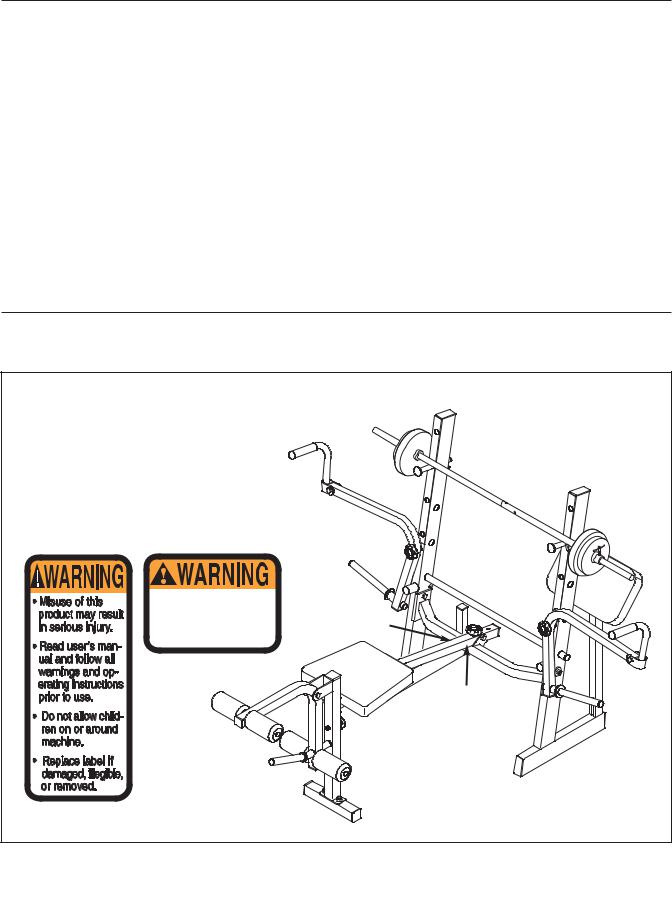
TABLE OF CONTENTS
WARNING DECAL PLACEMENT . . . . . . . . . . . . . . . . . . . . . . . . . . . . . . . . . . . . . . . . . . . . . . . . . . . . . . . . . . 2 IMPORTANT PRECAUTIONS . . . . . . . . . . . . . . . . . . . . . . . . . . . . . . . . . . . . . . . . . . . . . . . . . . . . . . . . . . . . . 3 BEFORE YOU BEGIN . . . . . . . . . . . . . . . . . . . . . . . . . . . . . . . . . . . . . . . . . . . . . . . . . . . . . . . . . . . . . . . . . . . 4 ASSEMBLY . . . . . . . . . . . . . . . . . . . . . . . . . . . . . . . . . . . . . . . . . . . . . . . . . . . . . . . . . . . . . . . . . . . . . . . . . . . 5 ADJUSTMENTS . . . . . . . . . . . . . . . . . . . . . . . . . . . . . . . . . . . . . . . . . . . . . . . . . . . . . . . . . . . . . . . . . . . . . . 10 EXERCISE GUIDELINES . . . . . . . . . . . . . . . . . . . . . . . . . . . . . . . . . . . . . . . . . . . . . . . . . . . . . . . . . . . . . . . 13 ORDERING REPLACEMENT PARTS . . . . . . . . . . . . . . . . . . . . . . . . . . . . . . . . . . . . . . . . . . . . . . . .Back Cover LIMITED WARRANTY . . . . . . . . . . . . . . . . . . . . . . . . . . . . . . . . . . . . . . . . . . . . . . . . . . . . . . . . . . . Back Cover
Note: A PART IDENTIFICATION CHART and a PART LIST/EXPLODED DRAWING is attached in the center of this manual. Remove the PART IDENTIFICATION CHART and PART LIST/EXPLODED DRAWING before beginning assembly.
WARNING DECAL PLACEMENT
The decals shown here have been placed on the weight bench. If a decal is missing or illegible, please call our Customer Service Department toll-free at 1-800-999-3756, Monday through Friday, 6 a.m. until 6 p.m. Mountain Time, to order a free replacement decal. Apply the decal in the location shown.
Keep hands and fingers clear of this area.
Decal 2
Decal 2
Decal 2
Decal 1
Decal 1
REEBOK and the Vector Logo  are registered trademarks and service marks of Reebok. This product is manufactured and distributed under license from Reebok International. NFL and the NFL shield design are registered trademarks of the National Football League.
2

IMPORTANT PRECAUTIONS
 WARNING: To reduce the risk of serious injury, read the following important precautions before using the weight bench.
1.Read all instructions in this manual before using the weight bench. Use the weight bench only as described in this manual.
2.It is the responsibility of the owner to ensure that all users of the weight bench are adequately informed of all precautions.
3.The weight bench is intended for home use only. Do not use the weight bench in any commercial, rental, or institutional setting.
4.Use the weight bench only on a level surface. Cover the floor beneath the weight bench to protect the floor.
5.Make sure all parts are properly tightened each time the weight bench is used. Replace any worn parts immediately.
6.Keep children under 12 and pets away from the weight bench at all times.
7.Keep hands and feet away from moving parts.
8.Always wear athletic shoes for foot protection while exercising.
9.Make sure that the cable remains on the pulley at all times. If the cable binds as you are exercising, stop immediately and make sure that the cable is on the pulley.
10.Always set both weight rests at the same height.
11.When using the backrest in a level or an inclined position, make sure that the support rod is inserted completely through the uprights and turned to the locked position.
12.The weight bench is designed to support a maximum user weight of 300 pounds, and a maximum total weight of 410 pounds. Do not place more than 110 pounds, including the barbell, on the weight rests. Do not place more than 50 pounds on the leg lever or the weight carriage. Do not place more than 30 pounds on either butterfly arm.
13.Always make sure there is an equal amount of weight on each side of the barbell when you are using it. When adding or removing weights, always keep some weight on both ends of the barbell to prevent the barbell from tipping.
14.Always place an equal amount of weight on each side of the weight carriage or on each butterfly arm.
15.Always secure the weights with the weight clips when they are mounted on the weight carriage.
16.When you are using the leg lever, place the barbell with the same amount of weight on the weight rests to balance the bench.
17.Always exercise with a partner. Your partner should be ready to catch the barbell if you cannot complete a repetition.
18.Always disconnect the lat bar from the cable when performing an exercise that does not require it.
19.If you feel pain or dizziness at any time while exercising, stop immediately and begin cooling down.
 WARNING: Before beginning this or any exercise program, consult your physician. This is especially important for persons over the age of 35 or persons with pre-existing health problems. Read all instructions before using. ICON assumes no responsibility for personal injury or property damage sustained by or through the use of this product.
3
BEFORE YOU BEGIN
Thank you for selecting the versatile NFL BY REEBOK® weight bench. The weight bench offers a selection of weight stations designed to develop every major muscle group of the body. Whether your goal is to tone your body, build dramatic muscle size and strength, or improve your cardiovascular system, the weight bench will help you to achieve the specific results you want.
For your benefit, read this manual carefully before using the weight bench. If you have additional questions, please call our Customer Service Department
toll-free at 1-800-999-3756, Monday through Friday,
6 a.m. until 6 p.m. Mountain Time (excluding holidays). To help us assist you, please note the product model number and serial number before calling. The model number is NFLB09530. The serial number can be found on a decal attached to the weight bench (see the front cover of this manual).
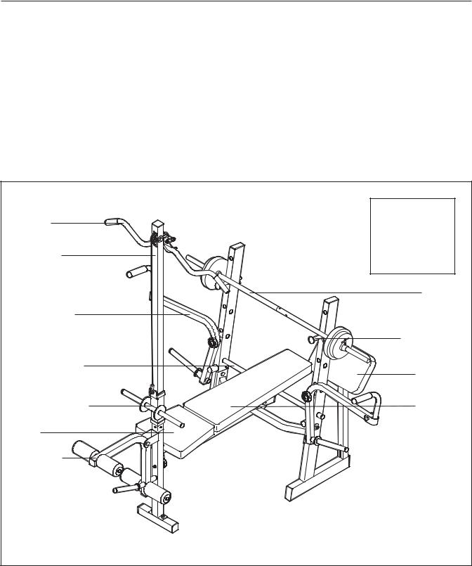
Before reading further, please review the drawing below and familiarize yourself with the parts that are labeled.
Lat Bar
Lat Tower
Butterfly Arm
Right Side
Adjustment Bar
Weight Carriage
Seat
Leg Lever
ASSEMBLED
DIMENSIONS:
Height: 80 in.
Width: 84 in.
Depth: 67 in.
Barbell
Weight Rest
Curl Pad
Backrest
Left Side
Note: The terms “right side” and “left side” are determined relative to a person sitting on the bench; they do not correspond to right and left on the drawings in the manual.
4
ASSEMBLY
Make Things Easier for Yourself
Everything in this manual is designed to ensure that the weight bench can be assembled successfully by anyone. However, it is important to realize that the versatile weight bench has many parts and that the assembly process will take time. Most people find that by setting aside plenty of time, assembly will go smoothly.
Before beginning assembly, carefully read the following information and instructions:
•Assembly requires two people.
•Place all parts in a cleared area and remove the packing materials. Do not dispose of the packing materials until assembly is completed.
•Tighten all parts as you assemble them, unless instructed to do otherwise.
•As you assemble the weight bench, make sure all parts are oriented as shown in the drawings.
•For help identifying small parts, use the PART IDENTIFICATION CHART.
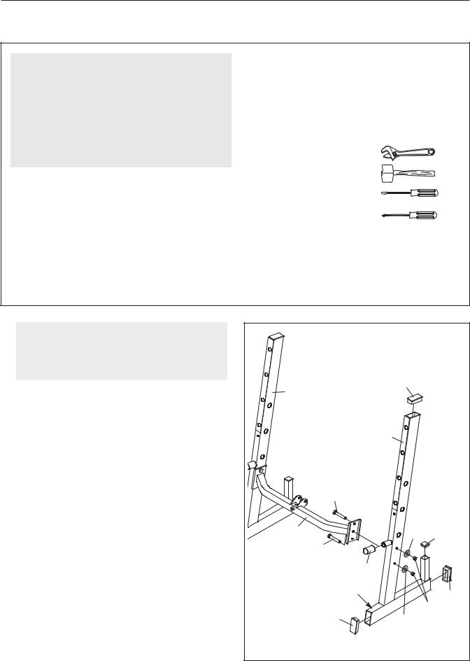
The following tools (not included) are required for assembly:
• Two adjustable wrenches
• One rubber mallet
• One standard screwdriver
• One Phillips screwdriver
•Lubricant, such as grease or petroleum jelly, and soapy water.
Assembly will be more convenient if you have a socket set, a set of open-end or closed-end wrenches, or a set of ratchet wrenches.
1. |
1 |
|
|
|
Before beginning assembly, make sure you |
|
|
|
|
understand the information in the box |
|
|
|
|
above. For help identifying small parts, use |
|
|
|
|
the PART IDENTIFICATION CHART. |
|
|
|
|
|
4 |
|
25 |
|
Press three 38mm x 75mm Inner Caps (25) and a |
|
|
|
|
|
|
|
|
|
35mm Square Inner Cap (32) into an Upright (4). |
|
|
|
|
Press a Rubber Bumper (16) onto the Upright. |
|
|
|
|
Attach the Upright (4) to the Crossbar (3) with two |
|
|
4 |
|
|
|
|
|
|
M10 x 55mm Bolts (48), two M10 Washers (50), |
|
|
|
|
and two M10 Nylon Locknuts (51). Make sure |
|
|
|
|
the warning decal is in the indicated position. |
|
|
|
|
Do not tighten the Locknuts yet. |
|
48 |
|
|
|
|
|
|
|
Repeat this step with the other Upright (4). |
|
|
|
|
|
3 |
|
50 |
32 |
|
|
|
||
|
|
48 |
|
|
|
|
16 |
|
|
|
|
Warning |
|
|
|
|
Decal |
|
25 |
|
|
|
|
|
|
|
25 |
|
51 |
|
|
50 |
|
|
|
|
|
|
5
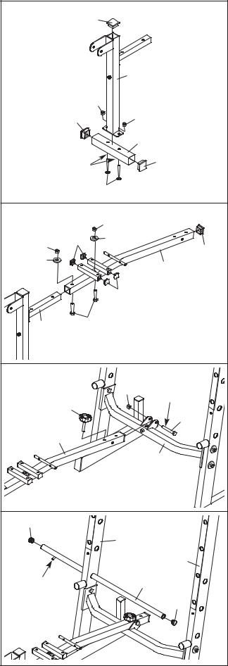
2. Press three 45mm Square Inner Caps (26) into |
2 |
|
|
|
|
the Bench Leg (2) and the Stabilizer (57). |
|
|
26 |
|
|
|
|
|
|
||
Orient the Stabilizer (57) so that the indents |
|
|
|
|
|
around the holes are on the bottom. Attach the |
|
|
|
|
|
Bench Leg (2) to the Stabilizer with two M10 x |
|
|
|
|
|
58mm Carriage Bolts (53) and two M10 Nylon |
|
|
|
|
2 |
Locknuts (51). Do not tighten the Locknuts yet. |
|
|
|
|
|
|
|
|
|
51 |
|
|
|
|
26 |
|
51 |
|
|
|
|
|
|
|
|
|
|
|
57 |
|
|
|
Indents |
26 |
|
|
|
|
|
||
|
|
|
|
53 |
|
3. Press a 38mm Square Inner Cap (27) and four |
3 |
|
|
|
|
25mm Square Inner Caps (24) into the Bench |
|
|
51 |
|
|
|
|
|
|
||
Frame (1). |
|
|
24 |
50 |
|
|
|
51 |
27 |
||
Attach the Bench Frame (1) to the Bench Leg (2) |
|
|
|
||
|
50 |
|
|
||
|
|
|
|
||
with two M10 x 48mm Bolts (52), two M10 |
|
|
|
1 |
|
|
|
|
|
||
Washers (50), and two M10 Nylon Locknuts (51). |
|
|
|
|
|
Do not tighten the Locknuts yet. |
|
|
|
|
24 |
|
|
|
|
|
|
|
|
2 |
|
52 |
|
|
|
|
|
|
|
4. Lubricate an M10 x 57mm Bolt (43) with grease. |
4 |
|
|
|
|
Attach the Bench Frame (1) to the Crossbar (3) |
|
|
|
|
|
|
|
|
|
51 |
|
with the Bolt and an M10 Nylon Locknut (51). Do |
|
|
|
|
|
not overtighten the Locknut; the Bench Frame |
|
|
39 |
|
Grease |
|
|
|
|
||
must be able to pivot easily. |
|
|
|
43 |
|
|
|
|
|
||
|
|
|
|
|
|
Tighten the Long Knob (39) into the Bench Frame |
|
|
1 |
|
|
(1) and the Crossbar (3). |
|
|
|
|
3 |
|
|
|
|
|
|
5. Press two 25mm Round Inner Caps (28) into the |
5 |
28 |
|
|
|
Adjustment Bar (13). |
|
|
|
||
|
|
|
|
|
|
Slide the Adjustment Bar (13) into the Uprights (4) |
|
|
|
|
4 |
|
|
|
|
4 |
|
and turn the Bar so that the locking pin wraps |
|
|
|
|
|
around the Upright. |
|
Locking |
|
|
13 |
|
|
|
|
||
Tighten the M10 Nylon Locknuts (51) used in |
|
Pin |
|
|
28 |
steps 1–3. |
|
|
|
|
|
6
 Loading...