

Redring Hotbox L318, Hotbox LP330 User And Installer Instructions
Page 1 of 13
Redring Hotbox Boiler
Models L318 and LP330
User and Installer Instructions
Please keep these instructions safe, should you move house,
please hand them over to the next occupier.
COMPLIANT TO : BS EN 60335-2, BS EN 55014-2 and BS EN 50081-1

Page 2 of 13
Redring Hotbox Boiler
THE HALOGEN BOILER, L318, LP330
HALOGEN POWERED WALLMOUNTED BOILER
USER&INSTALLERS INSTRUCTIONS
PLEASE KEEP THESE INSTRUCTIONS SAFE. SHOULD YOU MOVE HOUSE, PLEASE
HAND THEM OVER TO THE NEXT OCCUPIER.
1. Introduction
The Halogen Boiler is a wall-mounted appliance, suitable for installation onto small sealed heating systems.
It incorporates all the components for sealed system requirements, these include, pressure gauge, pressure
relief valve, expansion vessel, circulating pump and manual reset overheat thermostat. A manual air vent is
also located on the appliance. There are two controls on the appliance, one adjusts the water flow
temperature, and the other is an on/off switch. A 2 m long electrical flex with integral plug enables the
appliance to be connected into a standard 13A ring main socket or via the 24 hour plug in timer supplied.
2. Technical Specification
Performance Data
L318 LP330
Electrical Input kW 6 x 0.300 10 x 0.300
Heat Output to Water kW 1.71 2.85
Heat Output Convection kW 0.09 0.15
General Specification
L318 LP330
Product Catalogue Number 29-394601 29-394602
Halogen Bulb Heat Source 6 x 300W 10 x 300W
Electricity Supply 220 - 240V ~ 50 Hz 220 - 240V ~ 50 Hz
External Fuse (supplied plug) 10A 13A
Water Connections Flow 22 mm Copper 22 mm Copper
Water Connections Return 22 mm Copper 22 mm Copper
Expansion Vessel Charge 0.5 bar 0.5 bar
Minimum operating flow temp. 20°C 20°C
Maximum operating flow temp. 70°C 70°C
Page 3 of 13
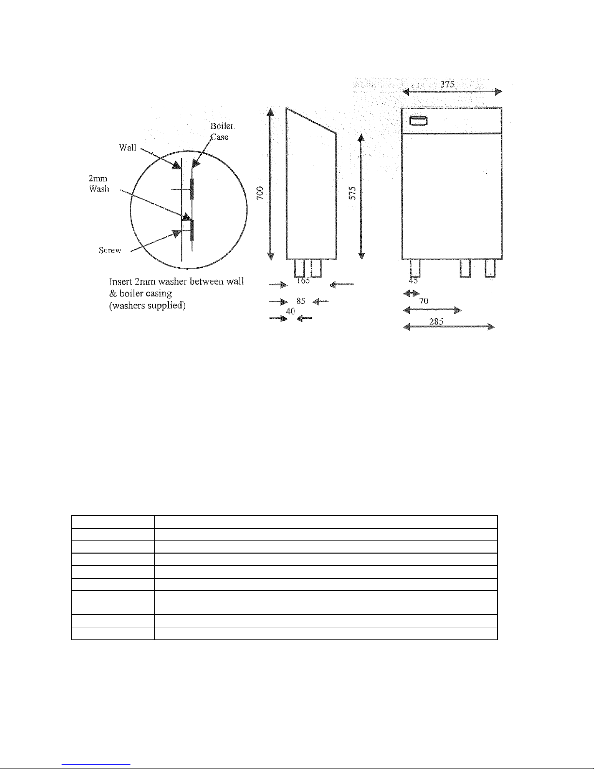
Overall Dimensions & Minimum Clearances
Clearances Operational Maintenance
Side
mm 5 5
Top mm 200 200
Bottom
mm 200 200
Front mm 5 500
3. Installation Requirements
Statutory Requirements
The installation should also be in accordance with the relevant recommendations in the current editions of
the following British Standards:
BS 7074: Pt 1 Expansion vessels and ancillary equipment for sealed water systems
BS 5449 Forced circulation hot water systems for domestic premises
BS 7671 Requirements for Electrical Installations. IEE Wiring Regulations.
BS 4814 Expansion Vessels using an internal diaphragm for sealed hot water systems.
BS 6798 Installation of gas fired boilers of rated input not exceeding 70 kW Net.
BS 6759: Pt 1 Safety valves
BS 1362 General purpose fuse links for domestic & similar purposes. (Primarily for use in
plugs).
BS 5376 Code of Practice for selection & installation of gas space heating
Boiler Location
The boiler is not suitable for external installation. The position selected must be within the building unless
protected by a suitable enclosure. There must be adequate space for installation, servicing and operation of
the boiler as well as adequate air circulation.

Page 4 of 13
If the boiler is to be placed in a cupboard this cupboard should not be used as a storage cupboard. Ventilation
should be provided as detailed below.
Ventilation
This boiler does not require a purpose provided air ventilation in the room, however it does require room air
to circulate through the boiler to ensure the convection heat output performance is maintained.
If the boiler is installed in an enclosure or small cupboard, there must be an equivalent ventilation free area
in the enclosure or small cupboard to that of the boiler.
Upper Ventilation Free Area These should be the same or larger than in the
appliance case mm
2
Lower Ventilation Free Area As above
Electrical Supply
This appliance must be earthed
The appliance is supplied with a 2 m electrical flex with integral fused plug, which requires a standard 220 240V ~ 50Hz supply via a normal ring main socket. If required, the plug connection can be made via the 24
hour plug in timer supplied.
All fuses must be ASTA approved to BS 1362
In the event of an electrical fault after installation of the boiler, preliminary electrical system checks must be
carried out. i.e. earth continuity, short circuit, polarity and resistance to earth.
Central Heating Systems
This boiler is designed specifically for use in small, pressurised, sealed system installations. The installation
must comply with BS 6798.
Safety Valve – The safety valve, which is pre-set at a maximum of 3 bar is an integral part of the boiler and
cannot be adjusted. Its relief outlet must be piped to a suitable outside position.
Pressure Gauge
This indicates the system fill pressure. It will show a higher pressure when the system is hot.
Circulating Pump
The circulating pump is located inside the boiler case. Its performance is suitable for all systems to which
the boiler should be connected.
Expansion Vessel
The expansion vessel, which is located inside the boiler case, has a capacity of 2.0 L, with a pre-charge of
0.5 bar.
The maximum heating system water content using this integral expansion vessel is 24.0 L. This is with a
cold fill of 0.5 bar.
Should the system volume be in excess of that specified, a second expansion vessel must be connected to the
heating system. BS 5449 gives further guidance for expansion vessel sizing.
Vessel Charge and Initial System Fill Pressure Bar 0.5 1.0 1.5
For Expansion Vessel Capacity
(Multiply the system Volume by)
0.0833 0.109 0.156
Total system water capacity using the integral
2.0 L expansion vessel
Litres 25.0
18.4
12.8
 Loading...