


Important Safety Instructions
When using this electrical equipment, basic safety precautions should always be followed, including the following:
1.READ AND FOLLOW ALL INSTRUCTIONS.
2.This appliance must be grounded.
3.Disconnect this product from the electrical supply before cleaning, servicing or removing the
cover.
4.To reduce the risk of injury, close supervision is necessary when the product is used near children or elderly persons.
5.Warning: Mount the unit onto a flat section of wall, well away from any potential splashes of water or spray and away from areas where direct moist or wet contact could occur.
6.Warning: Do not install the heater in a location where it may be subject to freezing.
7.Warning: Do not install a check valve or any other type of back flow preventer within ten feet of the cold water inlet.
8.The electrical installation must conform to current National Electrical Codes.
9.Warning: Do not switch the heater on if you suspect that it may be frozen. Wait until you are sure that it has completely thawed out.
10.The PowerStar is designed to heat potable cold water for domestic purposes. The maximum inlet water temperature it can handle is 86 degrees F. Contact Bosch Water Heating before specifying or installing the appliance in any other application.
11.Additional Canadian safety instructions:
a)As per the Canadian Electrical Code, C22.1-02 Section 26-744, an auxiliary terminal block must be fitted to the unit before connecting to the electrical supply (Kit Part N° “AE Canada Kit”). (See Page 7).
b)A green terminal (or a wire connector marked “G,” “GR,” “GROUND” or “GROUNDING”) is provided within the control. To reduce the risk of electrical shock, connect this terminal or connector to the grounding terminal of the electrical service of supply panel with a continuous copper wire in accordance with the Canadian Electrical Code, Part I.
c)This product shall be protected by a Class A ground fault circuit interrupter.
Contents
Specifications |
3 |
Installing the PowerStar |
3 |
Starting up the PowerStar |
8 |
How the PowerStar works |
9 |
Using the PowerStar |
10 |
Spare Parts |
11 |
Maintenance |
11 |
Troubleshooting |
12 |
Warranty |
15 |
SAVE THESE INSTRUCTIONS
Keep this guide in a safe place once your unit has been installed.
You may need to refer to it for general instructions or future maintenance.
2

Specifications
|
AE115 Unit |
AE125 Unit |
Voltage supply |
2 x 240V AC (Canada 240VAC) |
3 x 240V AC (Canada 240VAC) |
Amperage |
2 x 40 A (Canada 80 A) |
3 x 40 A (Canada 120 A) |
Maximum output |
17.25 kW |
26.85kW |
Temperature control range |
95°F to 131°F |
95°F to 131°F |
Pressure range |
15 psi to 150 psi |
15 psi to 150 psi |
Minimum flow rate |
0.6 US gal / min |
0.8 US gal / min |
Maximum flow rate |
See Graph 1, Page 8 |
See Graph 1, Page 8 |
Dimensions (excl. water couplers) |
15½” H x 151/4” W x 4½” D |
15½” H x 151/4” W x 4½” D |
Weight (without water) |
20 lbs |
22 lbs |
Note: The unit will work at lower supply voltages but the following changes will apply: |
||
Maximum output |
15kW at 220V |
22.5kW at 220V |
|
13kW at 208V |
20kW at 208V |
Temperature control range |
87°F to 116°F at 220V |
87°F to 116°F at 220V |
|
82°F to 108°F at 208V |
82°F to 108°F at 208V |
Maximum flow rate |
84% of maximum at 220V |
84% of maximum at 220V |
(refer to Graph 1, Page 8) |
75% of maximum at 208V |
75% of maximum at 208V |
Installing the PowerStar
WARNING:
If water supply has a high mineral content, a water softening system is strongly recommended. Damage to the water heater resulting from scale or hard minerals will not be covered under warranty.
DISCLAIMER:
In the Commonwealth of Massachusetts a licensed plumber or electrician must perform the installation. (Approval number: P1-09-25).
Locating the Powerstar
WARNING:
Do not install the water heater in an area where there is a chance of freezing. Damage to the water heater as a result of freezing will not be covered under warranty.
∙If being used in a public place, locate the heater out of easy reach to discourage vandalism.
∙Mount the unit onto a flat section of wall, well away from any potential splashes of water or spray and away from areas where direct moist or wet contact could occur.
Should it be necessary to service the Powerstar, observe the following clearances. These are not required clearances, but would facilitate any service work.
Recommended minimum clearances for servicing
Top |
12” |
Bottom |
6” |
Sides |
0” |
Front |
12” |
3
Mounting the Powerstar
WARNING:
The heater must only be installed in the orientation shown in Diagram 1 i.e., mounted in a vertical position with the water fittings located at the bottom of the heater. Under no circumstances should the heater be mounted differently.
∙Undo the retaining screws on the front cover and take the cover off the heater. Hold the back plate in position against the wall and mark the four mounting holes
∙Drill the holes and secure the heater using the four wood screws supplied.
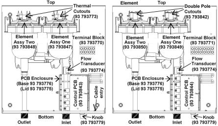
Diagram 1
AE115 Unit |
AE125 Unit |
Water Connections
WARNING:
Do not install a non-return check valve within 10 feet of the inlet.
WARNING:
Do not apply heat or solder to connections or pipe if they are already connected to the unit.
DISCLAIMER:
In the Commonwealth of Massachusetts a pressure relief valve shall be installed on the cold water side by a licensed plumber. (MGL 142 Section 19, Approval number P1-09-25)
∙The heater must be connected directly to the main cold water supply and not to pre-heated water. (The inlet water temperature must not be greater than 86°F.)
∙The heater must be installed with shutoff valves on both the inlet and outlet connections.
∙It is recommended that you use ¾ inch or ½ inch copper or high-pressure flex connections.
4

∙Do not use plastic piping within 3 feet on either side of heater.
∙Use Teflon tape for sealing pipe threads. Do NOT use pipe dope.
∙Remember to keep the hot water pipe runs as short as possible.
∙After the heater has been plumbed, and before you wire it, flush it with water to remove any debris or loose particles. Heater must be full of water and air purged before power is turned on. Failure to do so may make the heater inoperable.
∙The inlet and outlet connections are clearly marked on the heater. They each have a ¾ inch NPT connector.
∙Check the pressure of the main water supply. To operate correctly, the heater needs the following running pressures:
Recommended water pressures
Min water pressure |
15 psi (1 Bar) |
Max water pressure |
150 psi (10 Bar) |
Electrical connections
WARNING
The unit must be wired by a qualified electrician, in accordance with the current version of the National Electrical Code US) or Canadian Electric Code (Canada).
IMPORTANT
When the heater is not within sight of the electrical circuit breakers, a circuit breaker lockout or additional local means of disconnection for all non-grounded conductors must be provided that is within sight of the appliance. (Ref NEC 422.31.)
IMPORTANT
As per the Canadian Electrical Code, C22.1-02 Section 26-744, an auxiliary terminal block must be fitted to the heater before connecting to the electrical supply. This is available as a kit from Bosch Water Heating, Part Number “AE Canada Kit”. (Contact 866-330-2729).
US wiring
∙The minimum recommended wire size is 8 AWG. (The terminal block will accept cables up to 6 AWG size.)
∙The cable entry is via the 1 ¼ inch cable entry hole on the bottom right hand edge of the back plate.
∙Strip back the insulation on the power wires about ½ inch. Connect the live wires to the terminals marked “L1” and “L2.” There are two pairs of live wires in the AE115 and three pairs of live wires in the AE125. (See Diagrams 2 or 3 on page 6).
∙Any insulation on the ground wires should be stripped back about ¾ inch. The ground leads must be connected to the pillar terminal marked “GR”. (See Diagrams 2 and 3, Page 6).
∙Make sure the terminal block screws are tightened securely. Loose connections can cause wires to heat up.
∙Make sure that the ground wires are wrapped around its terminal stud and into the saddle washer. The nut should be tightened securely.
∙Attach the front cover and tighten the retaining screws.
5
 Loading...