


GLOW THERMOSTATIC ELECTRIC SHOWER
Installation and User Guide
(Large Print User Guide)
IMPORTANT:
This booklet should be left with the user after
installation and demonstration
1

Contents
Installation Guide
1 – Pack Contents ························································································································································· 3
2 – Installation Check List ············································································································································· 3
3 – Important Safety Information ································································································································ 4
4 – General Installation Layout Guide ·························································································································· 5
5 – Important Installation Information ························································································································ 6
6 – Fixing the Shower to the Wall ································································································································ 6
7 – Product Positioning Guide ······································································································································ 7
8 – Plumbing Connections ············································································································································ 8
9 – Electrical Connections ······································································································································· 9 - 10
10 – Fitting the Front Cover ··········································································································································· 11
11 – Riser Rail Fitting Instructions ·································································································································· 12
12 – Commissioning the Shower ···································································································································· 13
13 – Troubleshooting Checklist for the Installer ············································································································ 14
User Guide
1 – Important Safety Information ·································································· 15
2 – Operating the Shower ···································································· 16 - 18
3 – How Your Shower Works ································································ 19 - 20
4 – Routine Maintenance ··········································································· 21
5 – Periodical Maintenance ·································································· 21 - 22
6 – Troubleshooting – Self Help & Professional Service ····························· 22 - 24
7 – Spares ······························································································ 25
8 – Energy Related Product Directive (ErP) ··················································· 25
Warranty ····················································································· 27 - 28
IMPORTANT: This appliance can be used by children aged from 8 years and
above and persons with reduced physical, sensory or mental capabilities or lack
of experience and knowledge if they have been given supervision or instruction
concerning use of the appliance in a safe way and understand the hazards
involved.
The shower spray head MUST be cleaned regularly to remove scale and debris.
The frequency of the cleaning will vary according to the local water quality. If the
water outlet temperature becomes hot or the spray pattern becomes noticeably
uneven, immediately check the shower handset for blockage. See User Guide
Section 4 for cleaning instructions.
Do not operate shower if frozen, or suspected of being frozen. It must be
completely thawed out before using.
2

INSTALLATION GUIDE
1. Pack Contents
Please make sure ALL components are included before starting the installation.
□ Shower Unit
□ Shower Handset
□ Riser Rail Tube
□ Riser Rail Brackets x 2
□ Riser Rail Height Adjuster
□ Flexible Shower Hose
□ Soap Dish
□ Screw Pack
□ Installation and User Instructions
2. Installation Check List
□ Check that the water supply will satisfy requirements
□ Check that water and cable entry points of the unit meet requirements
□ Check that the electric supply will satisfy requirements
□ Select a suitable position for the shower
□ Follow plumbing installation section
□ Follow electrical installation section
□ Fit to the wall and connect the shower supplies
□ Commission the shower in the way described
□ Connect the umbilical when re-fitting the front cover
□ Familiarise yourself with the user operating instructions
3

3. Important Safety Information
MAINS SERVICE CONNECTIONS: The shower unit is supplied for right
entry and left entry, please see Section 8 and 9 for “Plumbing
Connections” and "Electrical Connections" for installation information.
IMPORTANT: To comply with water regulations, building regulations or
any specific local water company regulations and in accordance with
BS EN 806, a double check valve should be fitted where it is possible that
the shower head may come into contact with used water, for example in
the bath or a shower tray.
IMPORTANT: Check that there are no hidden cables or pipes before
drilling holes for the wall plugs. Choose a flat piece of wall to avoid the
possibility of distorting the back plate and making the front cover a poor
fit. Exercise great care when using power tools near water. The use of a
residual current device (RCD) is recommended.
IMPORTANT: Before connecting the water supply to the shower unit the
water supply pipe should be flushed out to remove all debris. After
flushing the pipework make the connection to shower inlet and ensure
the shower is positioned squarely on the wall with all fixing screws
tightened.
IT IS VERY IMPORTANT: To ensure that the terminal block screws are
fully tightened and that no cable insulation is trapped under screws, and
tighten periodically in accordance with BS 7671. The earth continuity
conductor of the electrical installation must be effectively connected to
all exposed metal parts of other appliances and services in the room in
which the shower unit is installed to conform with BS 7671. The unused
supply terminal block must not be used for any other purpose.
IMPORTANT: Ensure that the commissioning instructions are followed
before pressing the Start button. The unit MUST be filled with cold water
before the shower is used: Press Cooler button for more than 3 seconds
in order to cold fill the tank. (See Page 13 for details).
IMPORTANT: The shower unit MUST be fitted with a WRAS (Water
Regulations Advice Scheme) listed mains water isolating valve.
All Redring products are safe and without risk provided they are installed, used and
maintained in good working order in accordance with our instructions and
recommendations.
4

4. General Installation Layout Guide
• Plan your installation carefully. Check on the
nearest and most accessible rising main water
supply, this may be beneath the bath or in the
loft, where it feeds the water storage tank. Use
only the cold rising water main.
• If possible, avoid connecting the shower unit
where it will be affected by water drawn off by
another appliance.
• For example, the mains feed to a toilet, as this may
cause a drop in pressure to a level that is too low for the
shower unit to work correctly.
• A WRAS (Water Regulations Advice Scheme) listed
isolating valve must be fitted between the rising main
and the unit to comply with water regulations and to
allow for routine maintenance and servicing.
IMPORTANT!
This appliance can be used by children aged from 8 years and above and persons with reduced physical, sensory or
mental capabilities or lack of experience and knowledge if they have been given supervision or instruction concerning
use of the appliance in a safe way and understand the hazards involved.
5

5. Important Installation Information
• This shower unit is designed to be connected to a
15mm cold water mains supply.
• To enable the heating elements to be activated the
shower must be connected to mains water supply
with a minimum static pressure of 0.1MPa, 15lb/sq.
in, 1bar at a minimum flow rate of 8 litres per
minute. The maximum static pressure is 1MPa,
145lb/sq. in, 10bar.
• The shower unit must not be fitted where it may be
exposed to frost, for example, in an outdoor area.
The shower must not be used if suspected of being
frozen. Frost damage is not covered by the warranty.
• Plumbers jointing compound must not be used. In
instances of difficult joints use P.T.F.E. Tape. The use
of jointing compound will invalidate the product
warranty.
• Do not solder fittings near the shower unit as heat
can travel along pipe work and damage components.
• Complete all plumbing connections before making
the electrical connections.
NOTE: For the 9.5kW model, at the minimum pressure,
the flow rate must be 9 L/min.
• Position the shower on the wall so that it will NOT be
in the direct water spray from the shower handset
when fixed.
• The shower handset must be prevented from being
immersed in the bath or shower tray when hanging
down. The hose retaining ring on the soap dish can
be used for this purpose. (See diagram on Page 7).
• Remove the front cover fixing screws. Carefully
remove the front cover ensuring the flying lead plug
is disconnected from the PCB in the backplate.
• Having decided on the water and cable entry points
and chosen a flat piece of wall, hold the shower
vertically against the wall and mark the top two fixing
holes whilst ensuring the shower is square.
• Carefully drill the two holes as marked using a 5.5mm
masonry drill, after first making certain there are no
pipes or wires behind the proposed holes.
• Insert the wall plugs and screws provided leaving the
screw head proud by approximately 5mm. The
shower can now be hung on these screws.
• Make sure that the shower is positioned vertically
and square, now mark and drill the lower slotted
fixing hole. Then fix the shower to the wall. Do not
fully tighten the screws at this stage.
• The shower back plate and removable corner
mouldings have moulded cut out sections which are
clearly indicated to allow the chosen service entry
option to be cut out prior to final fix.
NOTE: The bottom screw should only be fitted during
final installation.
TIPS
• A piece of insulating or masking tape applied to
the wall before marking out the fixing holes will
help stop the drill from wandering, particularly
on tiled surfaces.
• When working near a basin or bath, insert the
plug in the waste fitting so that small parts
cannot be lost.
• Take care not to drop accessories or tools into
bath or shower tray.
IMPORTANT!
Under no circumstances should this shower unit be recessed (it must be fitted onto the finished wall surface). Do not
tile up to or seal around the unit at this may prevent air circulating and any condensation escaping.
Shower installation must be carried out by a suitably qualified person and be in accordance with BS 7671 (IET wiring
regulations), building regulations, water regulations and / or any specific local water company regulations in force
and should be in accordance with BS EN 806.
6. Fixing the Shower to the Wall
6

7. Product Positioning Guide
7
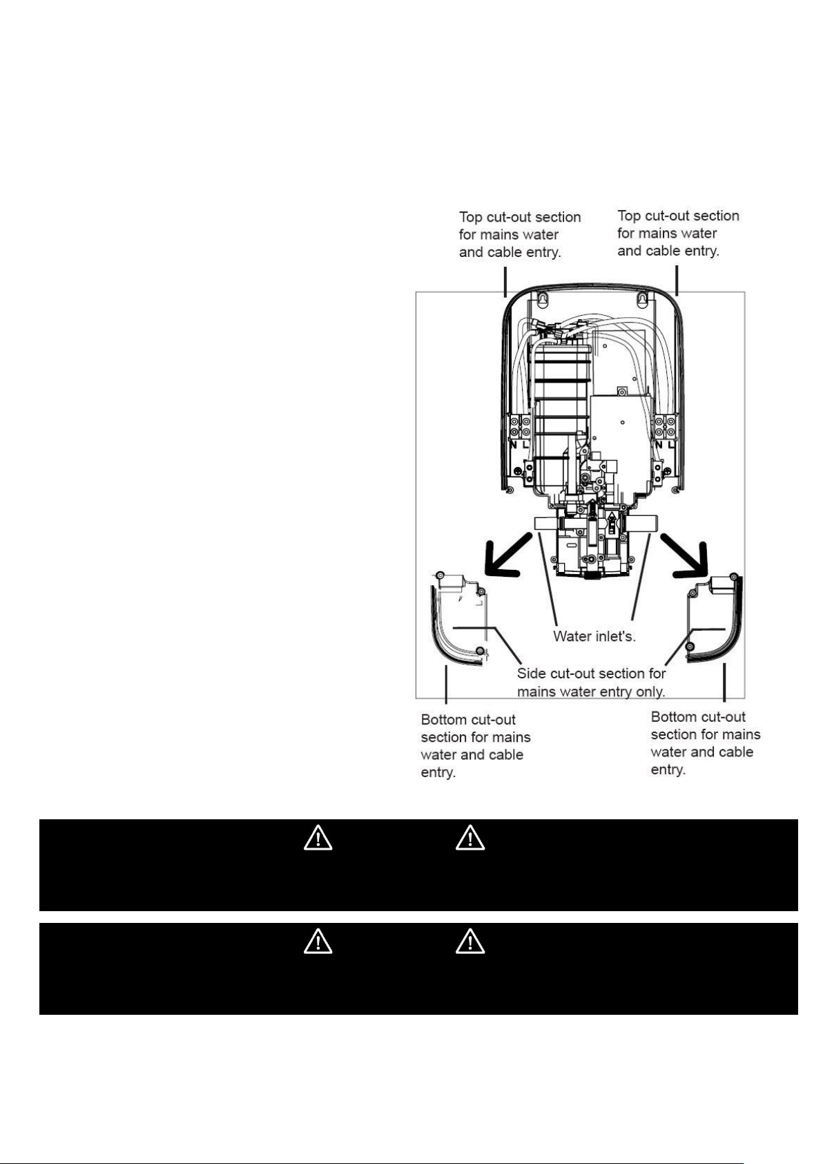
8. Plumbing Connections
The shower back plate incorporates into the lower right
and left side a removable corner section to allow easy
access when deciding on and connecting to the water
mains supply.
1. Remove the bottom right or left hand side corner
section giving access to the water inlet connection
point.
IMPORTANT: Before connecting the mains water supply
to the shower, flush out the pipe work to remove all
swarf and system debris. This is achieved by connecting
a suitable hose (e.g. Garden hose) to the pipe work and
turning on the mains water supply at the isolating stop
tap long enough to clear the debris to waste.
2. Turn off the mains water supply at the isolating tap.
3. Having decided on the direction of the water inlet
supply: Top (falling) Bottom (rising) or rear / side
inlet, it is necessary to remove the appropriate
knock out (thinned out plastic) cross section from
the back plate before commencing with the
installation. The connection to the unit is made
using a 15mm copper, stainless or plastic pipe with a
15mm compression elbow or 15mm push fit elbow.
IMPORTANT: Do not use excessive force when making
the connection to the unit.
4. If left hand water entry is desired, remove spring
clip and then blanking cap. Replace blanking cap
onto right spigot, ensuring it is fully seated, then
snap spring clip back into groove for retainment.
5. Now tighten the back plate fixing screws so the unit
is firmly fixed to the wall.
6. If rear entry pipe work is used we recommend the
use of a suitable sealant to seal around the incoming
pipe work to prevent water entering the wall.
7. Turn on the mains water supply and check for leaks,
paying particular attention to the water inlet
connections. At this stage no water can flow through
the unit.
IMPORTANT: Remember to replace the lower corner
section before refitting the front cover.
IMPORTANT!
Installation must comply with water regulations, building regulations, any specific local water company regulations and
should be in accordance with BS EN 806. A double check valve must be fitted with all flexible shower accessories where
it is possible that the shower handset may come into contact with used water e.g. In the bath or shower tray.
IMPORTANT!
Before turning on the water supply to the shower unit the water supply pipe should be flushed out to remove debris.
After flushing the pipework ensure that the shower unit is positioned squarely on the wall and tighten the screws.
Tighten all plumbing connections and check the pipework for leaks.
8

9. Electrical Connections
The electrical installation must be in accordance with the
current BS 7671 (I.E.T. wiring regulations) and part P of the
building and / or local regulations.
The shower unit is designed for a single phase 50 Hz AC
electrical supply.
1. The incoming cable should be hidden.
Connect as follows:
Earth cable to terminal marked
Neutral cable to terminal marked N
Live cable to terminal marked L
2. The outer sheath of the supply cable must be
stripped back to a suitable length and the
earth conductor must have an earthing
sleeve fitted.
3. Connect the cable to the terminal block.
Ensure that ALL the retaining screws are
VERY tight and that NO cable insulation is
trapped under the screws. Loose connections
can result in cable overheating.
IMPORTANT: Failure to ensure that the retaining
screws are VERY tight could result in a failure of
the terminal block.
IMPORTANT: DO NOT switch on the electricity
supply until the shower cover has been fitted.
IMPORTANT: Ensure front cover umbilical is
connected to the PCB in the backplate.
(See diagram on Page 11).
IMPORTANT: Follow these cut back cable guidelines,
to ensure the product has a
reliable electrical connection.
IMPORTANT: The unused
supply terminal block must not
be used for any other purpose.
Electrical Specifications
Normal Power Rating at
240V
Normal Power Rating at 230V
8.5kW - (40A MCB rating)
7.8kW - (40A MCB rating)
9.5kW - (40A MCB rating)
8.7kW - (40A MCB rating)
IMPORTANT: The heating elements on the UK models are
manufactured to 230-240V specification and will give a lower
kW rating if the voltage supply is below 240V.
The shower unit must be permanently connected to the
electrical supply, direct from the consumer unit via an
electrical isolation switch with a minimum contact gap of 3
mm. The switch must be readily accessible and clearly
identifiable and sited out of reach of a person using the
shower over a fixed bath or shower tray, unless the switch is
pull cord operated. The wiring must be connected to the
switch without the use of a plug or socket outlet.
The supply cable size is determined by the kW rating of the
product (as detailed on the rating plate fixed to the back
plate) and the distance between the shower and the
consumer unit. The table below is for guidance only. You
should always consult a qualified electrician to establish the
correct cable for your installation.
DIRECT CLIPED Cable Run Guide
kW
RATING
NOMINAL
CURRENT
AT 240V
MINIMUM
RATING
ISOLATING
SWITCH
FUSE
RATING
MAX CABLE
RUN
6mm²
10mm²
8.5
35.5A
40 A
40 A
23 m
38 m
9.5
39.6A
40 A
40 A
21 m
32 m
IMPORTANT!
Ensure that the terminal block screws are fully tightened, and that no cable insulation is trapped under the screws.
Terminal block screws should be tighten periodically in accordance with BS 7671.
The earth continuity conductor of the electrical installation must be effectively connected to all exposed metal parts of
other appliances and services in the room in which the shower unit is installed to conform with BS 7671.
9
 Loading...