


IMPORTANT:
This booklet should be left with the user after
installation and demonstration.
Installation and User Guide
EXPRESSIONS REVIVE and
EXPRESSIONS REVIVE-PLUS
SMARTFIT 2 ELECTRIC SHOWERS

2
THIS APPLIANCE CAN BE USED BY CHILDREN AGED FROM 8 YEARS AND
ABOVE AND PERSONS WITH REDUCED PHYSICAL, SENSORY OR MENTAL
CAPABILITIES, OR LACK OF EXPERIENCE AND KNOWLEDGE IF THEY
HAVE BEEN GIVEN SUPERVISION OR INSTRUCTION CONCERNING USE OF
THE APPLIANCE IN A SAFE WAY AND UNDERSTAND THE HAZARDS
INVOLVED.
CHILDREN SHALL NOT PLAY WITH THE APPLIANCE.
CLEANING AND USER MAINTENANCE SHALL NOT BE MADE BY CHILDREN
YOU MUST DESCALE THE SHOWER HANDSET REGULARLY.
DO NOT SWITCH THE APPLIANCE ON IF YOU SUSPECT THE APPLIANCE
OF BEING FROZEN. WAIT UNTIL YOU ARE SURE IT HAS THAWED OUT.
Your shower has been designed for convenience, economy and safety of use, provided that it is
installed, used and maintained in good working order and in accordance with our instructions and
recommendations.
ALL WIRING AND INSTALLATION MUST BE SUPERVISED BY A SUITABLY
QUALIFIED PERSON.
THIS APPLIANCE MUST BE EARTHED.
The installation must be in accordance with the current edition of BS.7671 (
the ‘IET Wiring
Regulations’)
and ‘Part P’ of the ‘
Building Regulations’
in force at the time of installation.
Installations outside England and Wales must also conform to any local regulations in effect
This appliance is intended to be permanently connected to the fixed electrical wiring of the mains
supply with its own dedicated supply.
This appliance must
NOT
be fitted where it may be subjected to freezing conditions.
DO NOT
switch the appliance on if you suspect it of being frozen.
Wait until you are sure it has thawed out.
This appliance is not suitable for mounting into steam rooms or steam cubicles.
Isolate the mains electrical and water supply before removing the appliance front cover.
DO NOT
fit any sort of tap or control on the appliance outlet.
The appliance is designed to have an open outlet and should only be used with the Manufacturer’s
recommended fittings.
THIS SHOWER IS APPROVED (EN-60335) WITH THE HANDSET PROVIDED
AND UNDER NO CIRCUMSTANCES MUST ANY HANDSET THAT IS NOT
APPROVED BY THE MANUFACTURER BE USED WITH THIS PRODUCT.
YOU MUST REGULARLY INSPECT THE HANDSET FOR WEAR AND
DAMAGE AND REPLACE IF NECESSARY, WITH OUR APPROVED PART.
Take care to avoid restricting the outlet of the pressure relief device (fig.19).
If water is discharged from the pressure relief device, maintenance will be required before the
appliance can be safely used.
We
DO NOT
recommend this appliance be used in heavy or unsupervised commercial
applications.
IMPORTANT SAFETY INFORMATION
3
The following points will help you have a greater understanding of how your shower works:
The heating elements operate at a constant rate, dependent on your chosen power setting.
The water temperature is achieved by adjusting the rate of water flow.
The higher the water flow the lower the temperature and vice versa.
The temperature of the water supplied from the mains can vary considerably throughout the year
from 5 to 20°C.
This means that in the winter, flow rate will be less than in the summer to achieve the same outlet
temperature.
In summer the ‘ECO’ power setting may give adequate hot water.
Your shower is designed to stabilise temperature changes caused by water pressure
fluctuations.
These can result from toilets being flushed or taps being turned on and off.
When this happens your showering temperature will be held within a controlled band, provided
that the minimum pressure required by the shower is maintained (see ‘plumbing’ page.5).
If the water pressure falls below the minimum pressure required, it is likely that the pressure
switch will turn off the power to the heating elements, resulting in a cold shower.
WARNING:
ALL WIRING AND INSTALLATION MUST BE SUPERVISED BY A SUITABLY
QUALIFIED PERSON.
DO NOT INSTALL THIS SHOWER WHERE IT MAY BE SUBJECTED TO
FREEZING CONDITIONS.
1
ADVICE TO USERS
HOW TO INSTALL YOUR SHOWER
4
We recommend that the installation is done in the following sequence.
a. Fixing the shower to the wall (see note below) b. Plumbing c. Electrical connections
However, we recommend you determine the best configuration for your water inlet
options before fixing the shower to the wall, as it may be easier to adjust/fit connections
whilst unit is still ‘in-hand’.
a. FIXING THE SHOWER TO THE WALL
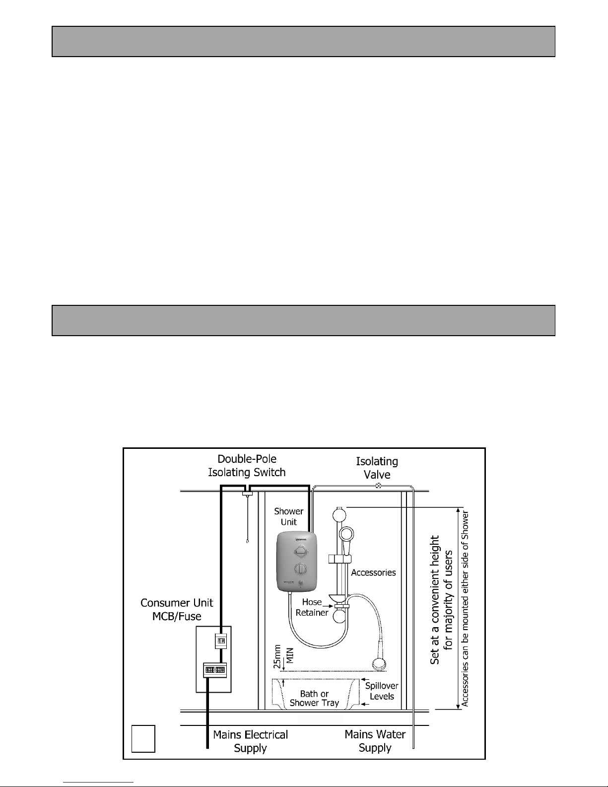
1. Position the riser rail at a convenient height for majority of users (fig.1) and mark its position
(see fig.12 for accessory details).
2. Position the shower unit so that the showerhead cannot be immersed in the bath or shower tray
when hanging down.
Choose a flat piece of wall to avoid the possibility of distorting the backplate thus making the
front cover a poor fit.
3. Adjust the position to get the most convenient arrangement taking the following into account.
DO NOT MOUNT THE UNIT IN THE DIRECT HANDSET SPRAY.
The handset must not be able to come into contact with used water in the cubicle,
bath or basin.
If it can, even after the hose has been retained by hose-retainer (fig.12), a vacuum breaker
must be fitted.
4. Fix the riser rail with screws provided (fig.12)
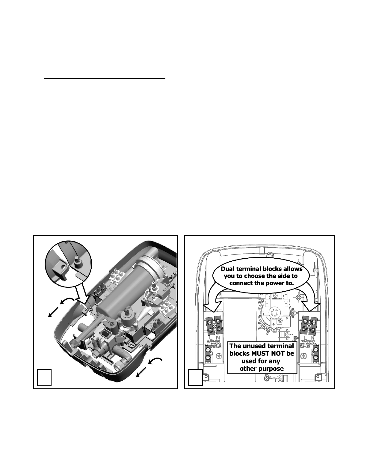
5. Remove the front cover by undoing the retaining screws at the top and bottom of the unit and
lifting the cover off.
6. Decide the position of the electrical cable into the unit.
Your shower offers the ability to have the connections on the right side or the left (see fig.3).
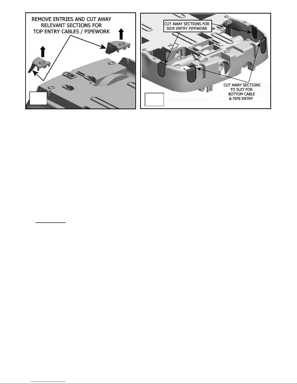
If the top entries are chosen, remove the cable/pipe entry from fixing kit bag and cut away as
shown (fig.4a).
If rear, bottom or side entries are chosen, remove the relevant cable/pipe entry from the
detachable lower section as shown (fig.4b).
2
3
5
7. Your shower is provided with 6 x wall-fixing positions in the backplate (fig.19)
These have been especially designed to match a number of previous ‘Redring Showers’,
as well as providing flexibility for new installations.
The 3 x top-fixing holes are a ‘key-hole’ slot design (‘k’ or ‘l’ fig.19), and the single most
convenient should be marked and drilled first.
Tighten fixing screw with head protruding about 10mm from the wall and hook the backplate
over the screw head. This allows for correct and accurate alignment of your shower before
marking and fixing the bottom positions.
Mark and drill the other 2 x most convenient wall fixing slots (‘m’ fig.19),
ensuring the slot in
the detachable lower section is used.
Remove the detachable lower section by lifting away from the 2 x fixing posts/pegs (fig.2).
Tighten fixing screw in main shower, leaving the detachable lower section screw until later.
You may wish to leave both fixing screws loose at this stage, as the holes are elongated to allow
for adjustment after other connections have taken place.
b. PLUMBING
WARNING:
ENSURE THAT THE MAINS WATER SUPPLY MEETS THE REQUIREMENTS BELOW BEFORE
CONTINUING INSTALLATION.
The shower unit must be connected to the mains cold water supply.
This must have a minimum supply running pressure of 100kPa (1.0 bar, 15 psi) at a minimum
flow rate of 8 litres/minute*.
The maximum static supply pressure must be no greater than 1000kPa (10 bar, 150 psi).
*
Minimum running pressure must be obtained at 9 litres/minute for 9.5kW.
WARNING:
BEFORE CONNECTING THE PIPE WORK TO THE SHOWER, ENSURE THAT THE PIPE WORK
IS FULLY FLUSHED OUT.
1. It is recommended that a WRAS (Water Regulations Advisory Scheme) listed isolating valve is
fitted to the incoming mains cold water before the shower unit.
This will allow the unit to be serviced or exchanged without having to turn off the water at the
water stop valve.
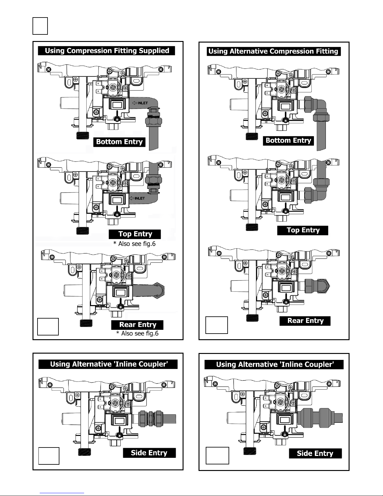
2.
Connect the mains water supply to the shower using Ø15mm copper pipe (BS.EN.1057) or
Ø15mm plastic pipe (with insert).
We recommend the use of copper olives.
If you choose to use a ‘push-fit’ connection rather than the compression elbow supplied (see
fig.5 and details on page.8),
DO NOT
use stainless steel or chrome plated pipe work.
In multiple installations, calculate correct pipe work sizes to maintain adequate flow to each unit.
4b
4a
6
Showing Right Side Entry
Left Side Entry is available for all options by exchanging the fitted end cap (fig.7)
5
5a
5b
5c
5d
 Loading...