

Page 1
Tel +1 (717) 767-6511
+
+
+
+
+
1.25
(31.8)
0.75
0.022
(0.56)
0.05 (1.3)
1.65 (42)
0.08
2.00
1.20
0.13
3.38
2.75
2.00 (50.8)
DIA. MOUNTING
FACE
0.375
(9.53)
DIA. SHAFT
#8-32 UNC
x0.30" (7.6) DP.
4 PL., EQUALLY
SPACED
1.50 (38.1) DIA.
BOLT CIRCLE
0.99 (25.1) DIA
FLANGE
(2)
(19)
(50.8)
(85.8)
(69.9)
(30.5)
(3.3)
Fax +1 (717) 764-0839
www.redlion.net
MODEL ZCH - QUADRATURE OUTPUT ROTARY PULSE GENERATOR
MODEL ZFH and ZGH - QUADRATURE OUTPUT LENGTH SENSORS
(Replaces MODELS RPGQ, LSQS and LSQD respectively)
100, 200 & 500 PULSES PER REVOLUTION
QUADRATURE CURRENT SINKING OUTPUTS TO 50 KHz
For position measurement, bi-directional counting
and systems with mechanical backlash
SEALED PRECISION BALL BEARINGS
RUGGED CAST ALUMINUM HOUSING
3/8" DIA. STAINLESS STEEL SHAFT
WIDE INPUT SUPPLY VOLTAGE RANGE & LOW CURRENT OPERATION
VARIOUS CABLE LENGTHS AVAILABLE
Bulletin No. ZCH/ZFH-A
Drawing No. LP0738
Effective 10/09
DESCRIPTION
The units are rugged, incremental encoders that convert shaft rotation into a
current sinking pulse train.
Internally, a single L.E.D. light source and a photologic sensor in conjunction
with a shaft-mounted, durable, metal-etched encoder disc, provides signal
accuracy and reliability to 50 KHz. The DC input power supply requirement is
a versatile +8 to +28 VDC, and is reverse polarity protected. The NPN Open
Collector Transistor Output is current limited to 40 mA and is compatible with
most RLC counters, rate indicators, controllers and accessories.
All units are packaged in a rugged cast aluminum housing with a gasketed,
rear aluminum cover. The 3/8" (9.53 mm) diameter heavy duty stainless steel
shaft and sealed, lifetime-lubricated precision ball bearings are preloaded for
minimum end play and rated for continuous use up to 6000 RPM. They are
designed to meet NEMA 13/IP54 environmental requirements. All units are
supplied with 10 feet (3M) of PVC jacketed 4-wire, 22 AWG cable with
stranded shield wire and 100% foil shield coverage.
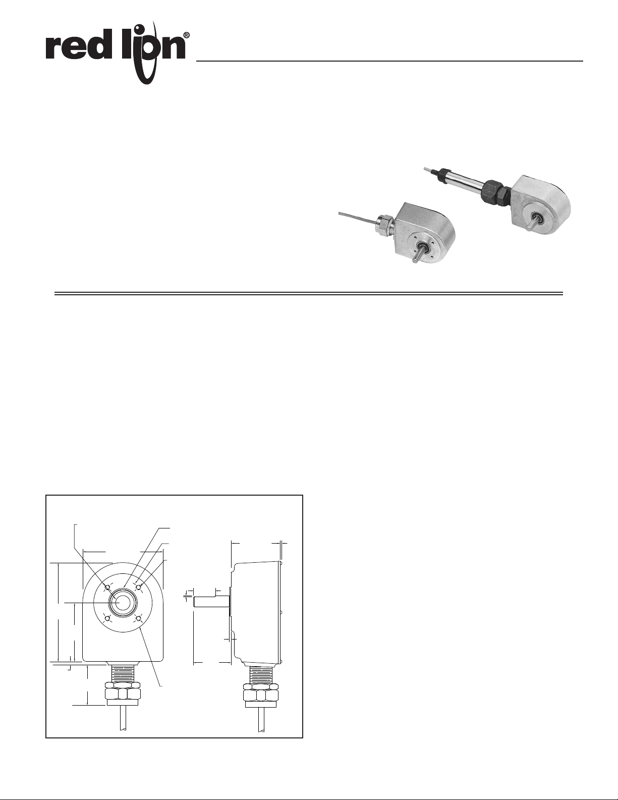
ZCH DIMENSIONS In inches (mm)
ROTARY PULSE GENERATOR
The ZCH can be direct-coupled to a machine shaft by means of a flexible
bellows, spring or rubber sleeve type coupler, etc., that allows for axial and radial
misalignment. They can also be coupled with instrument timing belts and pulleys
or gears. The housing may be rigidly face-mounted with the 4, #8-32 threaded
holes. The 4-wire shielded cable exits through a cord connector.
LENGTH SENSOR
The length sensors are available in both Single Ended Shaft (ZFH) and
Double Ended Shaft (ZGH) versions, both of which include a Stainless Steel
Handle Tube for mounting and 10 feet (3.05 M) of 4-wire shielded cable. When
mounted to a Length Sensor Hinge Clamp Assembly (See Model LSAHC001)
and coupled with one or two Measuring Wheels (See Measuring Wheels), a low
cost, versatile and highly accurate length measurement system can be
configured.
LENGTH SENSOR MEASUREMENT ACCURACY
Factors which affect measurement accuracy include Measuring Wheel
accuracy and wear, and material conditions. Ideally, materials which are hard,
thin and strong provide good readings. Conversely, soft, thick and elastic
materials can present problems in obtaining true readings. Count or Rate
Indicators with “input scaling” can compensate for Measuring Wheel wear and
material elasticity and compliance errors.
LENGTH SENSOR ACCESSORIES
The Length Sensor Hinge Clamp Assembly provides an easy method for
attachment & mounting the Length Sensors and LSCB1 Conversion Bracket.
The removable top on the solid aluminum LSAHC mounting block allows
quick installation of the Length Sensor handle tube and provides secure
clamping retention. The mounting block steel shaft pivots freely in oil
impregnated sintered bronze bushings, and aluminum right angle brackets
allow mounting the assembly via clearance holes for 1/4" (6.35 mm) dia. bolts
(See LSAHC Dimensions & Mounting).
Open Collector Output Wiring
The ZCH, ZFH, and ZGH series of sensors have open collector outputs. An
open collector output brings the uncommitted collector of the encoder switching
device to the external world. Because the collector element is not associated
with the sensor supply voltage, the sensor output collector may be “pulled up”
to external voltages (40 VDC max.) different than the encoder supply voltage .
NPN open collector outputs are current sinking devices. An output signal will
not be generated unless a pull-up resistor is connected from the open-collector
to the positive side of an external supply. The same supply can be used for
powering the unit and for the pull-up resistor.
1
Page 2
1.65
0.08 (2.03)
0.75
0.04
1.20
MAX.
(30.5)
(41.9)
(1.0)
(19.0)
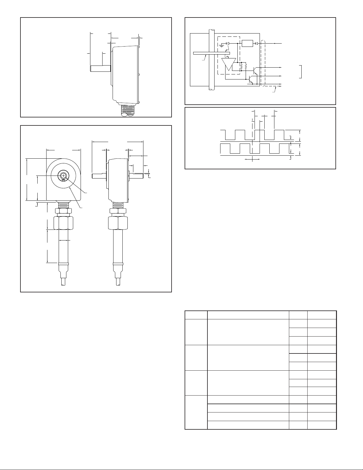
ZFH DIMENSIONS In inches (mm)
.75 (19) DIA.
2.75
(69.8)
2.06
(52.3)
2.00
(50.8)
.13 (3.3)
3.38
(85.8)
2.75 (69.9)
4.00 (101.6)
1.65 (41.9)
0.375 (9.52)
DIA. SHAFT
2.00 (50.8) DIA.
.04
(1.0)
.08
(2.03)
MAX.
USABLE SHAFT
LENGTH
1.08 (27.4)
REF., TYP. 2
.75
(19.0)
TYP. 2
.022 (.56)
TYP. 2
LED
REGU-
LATOR
RED
WHT
BLK
COMMON
8-28VDC @ 30mA
V = 30VDC MAX.
V = 1V MAX. @ 40mA
OL
OH
SHAFT
METAL
ETCHED
OPTICAL
DISC
BARE STRANDED SHIELD WIRE
CONNECTED TO INSTRUMENT
COMMON FOR INCREASED
NOISE IMMUNITY
SENSOR
ARRAY
(TYP.) 50mA MAX.
GRN
CHANNEL A
CHANNEL B
VOLV
OH
COMMON
OH
V
OL
V
COMMON
C.W.C.C.W.
SHAFT ROTATION
(NOTE 1)
CHAN. B
CHAN. A
(NOTE 4)
"c"
"a" "b"
(NOTE 3)
1 CYCLE (360°) (NOTE 2)
This is the side view of the Model
ZFH. All other dimensions (including
the handle tube) are the same as
the Model ZGH. See below.
ZGH DIMENSIONS In inches (mm)
EQUIVALENT CIRCUIT & CONNECTIONS
NOTES:
1. Channel A leads Channel B for clockwise shaft rotation when viewed from
housing front. Conversely, Channel B leads Channel A for Counterclockwise
shaft rotation.
2. The number of lines on the optical disc determines the Pulses Per Revolution
(PPR).
3. Duty Cycle is the relationship of output “High” time, “a”, to output “Low”
time, “b”, and is expressed as a High/Low percentage ratio, ie....% High time
= a/(a+b) x 100; % Low time = b/(a+b) x 100.
4. Quadrature Phase “c” is specified as the lead or lag between Channel A & B
in electrical degrees. Nominally 90° (1/4 cycle).
SPECIFICATIONS
ELECTRICAL SPECIFICATIONS
1. SUPPL Y V OLT AGE: +8 to +28 VDC (including power supply ripple) @ 50
mA max. (30 mA typ.); Reverse polarity protected.
2. OUTPUTS: NPN Open Collector Transistor, VOH = 30 VDC max., VOL = 1
V max @ 40 mA. Output current is limited to 40 mA. Incremental - Two
square waves in quadrature with Channel A leading B for clockwise rotation.
3. OUTPUT FREQUENCY: Up to 50 KHz
4. OUTPUT DUTY CYCLE: Channel A & B: 50/50 nominal. (See Figure 1,
Note 3)
5. QUADRATURE OUTPUT PHASE: 90° ±15° (See Figure 1, Note 3)
6. CABLE CONNECTIONS: RED = +VDC; BLACK = Common;
WHITE = Channel A Output; GREEN = Channel B Output.
MECHANICAL SPECIFICATIONS
1. MAXIMUM MECHANICAL SPEED: 6000 RPM
2. RADIAL SHAFT LOAD: 15 lbs. max. (66.7N)
3. AXIAL SHAFT LOAD: 15 lbs. max. (66.7N)
4. STARTING TORQUE: 3 oz.-in. (21.2N-mm)
5. MOMENT OF INERTIA:
Single Shaft = 1.03 x 10⁻⁴ oz. - in. - sec.2 (7.30 x 10⁻⁴N - mm - sec2)
Dual Shaft = 1.30 x 10⁻⁴ oz. - in. - sec.2 (9.21 x 10⁻⁴N - mm - sec2)
6. OPERATING TEMPERATURE: 0°C to +70°C
7. WEIGHT (LESS CABLE):
ZCH: 14.3 oz (406 g)
ZFH: 22.0 oz (623 g)
ZGH: 22.7 oz (643 g)
LENGTH SENSOR MOUNTING CONSIDERATION
1. Length Sensors should be mounted so measuring wheel(s) contact ribbon,
strip or web as it passes over a roller. As an alternative, wheel(s) can be driven
by roller surface next to material being measured.
2. Note: The weight at the Length Sensor unit provides sufficient traction for
accurate operation when mounted, with arm angle from horizonal not
exceeding ±30o.
3. T ension on signal cable can cause wheel(s) to lift. Make sure cable is clamped
to machine frame near the unit and allow slack.
ORDERING INFORMATION
MODEL NO. DESCRIPTION PPR PART NUMBER
100
ZCH0100C
ZCH
ZFH
ZGH
Rotary Pulse Generator
(Replaces RPGQ)
Length Sensor
Single Shaft
(Replaces LSQS)
Length Sensor
Double Shaft
(Replaces LSQD)
Flexible Coupling (1" Length) 0.250" - 0.375"
RPGFC
Flexible Coupling (1" Length) 0.375" - 0.375"
Flexible Coupling (1" Length) 0.375" - 0.500"
Flexible Coupling (1" Length) 0.375" - 6 mm
Note: For 25 foot cable, replace the last character of the part number (“C”) with “D”.
For 50 foot cable, replace the last character of the part number (“C”) with “E”.
2
200
500
100
200
500
100
200
500
--
--
--
--
ZCH0200C
ZCH0500C
ZFH0100C
ZFH0200C
ZFH0500C
ZGH0100C
ZGH0200C
ZGH0500C
RPGFC002
RPGFC003
RPGFC004
RPGFC006
Page 3

LENGTH SENSOR ACCESSORIES
Cast
Alum.
.376"
(9.6)
Bore
+.001"
-.000"
8-32 UNF
Set Screw
3/8"
(9.5)
Round Section Replaceable
Tire .210" Section Dia.
Black Neoprene
Diamond Knurled Aluminum
Tread
10-32 UNF
Set Screw
1"
(25.4)
Alum.
Cast
.376"
-.000"
+.001"
(9.6)
Bore
.376"
(9.6)
Bore
+.001"
-.000"
Tan, Smooth Polyurethane
Tread
10-32 UNF
Set Screw
Alum.
Cast
1"
(25.4)
SEPARATE LENGTH MEASURING WHEELS - DIMENSIONS In Inches (mm)
WHEEL
CODE
OR
FOR USE ON: Metal, paper,
foil, film and hard plastics.
Line contact on material
being measured,
convenient when available
measuring track is narrow
or for measuring on end of
roller beside passing
material.
Max. Speed: 600 RPM
WHEEL
CODE
OF
FOR USE ON: Soft, smooth
materials such as soft
paper, matting,
cardboard, fine weave
textiles. Broad wheel
tread minimizes contact
pressure and tan
polyurethane tread
minimizes marking.
Max. Speed: 600 RPM
Balanced version of 1ft.
circumference available.
Balanced to ANSI S2.191989 Quality Grade 6.3 @
3000 RPM.
WHEEL
CODE
OK
FOR USE ON: Rubber,
coarse weave fabrics,
rough wood surfaces,
foam, insulation.
Max. Speed: 600 RPM
Balanced version of 1ft.
circumference available.
Balanced to ANSI S2.191989 Quality Grade 6.3
@ 3000 RPM.
SELECTING APPROPRIATE WHEEL SIZE & PPR (Pulses Per Rev.) OF ROTARY PULSE GENERATOR
When the desired output of a length sensor and wheel combination is either
in inches, feet, yards, or meters selection of the proper combination is relatively
straight forward. For example, with a 1-foot wheel circumference, a 1 PPR
Rotary Pulse Generator will deliver 1 pulse/ft, 12 PPR would deliver 12 pulses/
ft (1 pulse/inch); 100 PPR would yield 100 pulses/ft; and 120 PPR would permit
measuring to 1/10th of an inch (1/120th of a foot).
WHEELS & REPLACEMENT TIRES FOR CODE OR WHEELS
ORDERING INFORMATION
WHEEL CODE
OR
OF
BF (Balanced)
CIRCUMFERENCE PART NUMBER
1 foot (1/3 yd) ±0.40% WF1000OR
1/3 meter ±0.40% WM0333OR
4/10ths yard ±0.40% WY0400OR
4/10ths meter ±0.40% WM0400OR
1 foot (1/3 yd) ±0.35% WF1000OF
1/3 meter ±0.30% WM0333OF
4/10ths yard ±0.30% WY0400OF
4/10ths meter ±0.30% WM0400OF
1 foot (1/3 yd) ±0.40% WF1000BF
TOLERANCE
WHEEL CODE CIRCUMFERENCE TOLERANCE PART NUMBER
OK
BK (Balanced) 1 foot (1/3 yd) ±0.35% WF1000BK
Replacement Tires
for OR Wheels
Note: After installation of measuring wheels, ensure guards,shields or other
devices are in place to protect personnel from rotating equipment.
1 foot (1/3 yd) ±0.35% WF1000OK
1/3 meter ±0.30% WM0333OK
4/10ths yard ±0.30% WY0400OK
4/10ths meter ±0.30% WM0400OK
1 foot (1/3 yd) TORF1000
1/3 meter TORM0333
4/10ths yard TORY0400
4/10ths meter TORM0400
3
Page 4

MODEL LSAHC - LENGTH SENSOR HINGE CLAMP ASSEMBLY
The Length Sensor Hinge Clamp Assembly provides an easy method for
attachment and mounting of the Length Sensors and LSCB1 Conversion
Bracket. The removable top on the solid zinc LSAHC mounting block
allows quick installation of the Length Sensor handle tube and provides
secure clamping retention. The mounting block pivots freely in zinc right
angle brackets to allow mounting the assembly via clearance holes for 1/4"
dia. bolts.
The lock washers must be used as indicated (between the bolt head and
the top clamp piece). Assemble the top clamp piece as follows.
1. Tighten both bolts so that the top clamp half draws down evenly on
the sensor tube.
2. Tighten the bolts until both lock washers are flat.
3. Then turn each bolt an additional ½
to ¾ turn.
DIMENSIONS In inches (mm)
FRONT
VIEW
TOP
VIEW
(86.4)
2.5 (63.5)
1.25
(31.8)
3.4
2.9
(73.7)
4X Ø 0.31 (7.9)
Lock washers (2) must be
installed between bolt heads
and top clamp piece.
.25 (6.3)
E-clip retaining ring (2)
must be installed in slots.
.88
(22.4)
SINGLE WHEEL
.85
2.93 (74.4)
(21.6)
DUAL WHEEL 4 (101.6)
Model ZGH Shown
WHEEL
RADIUS
OMITTED ON
SINGLE SHAFT UNITS
THIS WHEEL AND SHAFT
6.9 (175.3)
CAUTION: Downward tension
on signal cable can cause
wheel(s) to lift. Make sure
cable is clamped to
machine frame near
encoder and allow slack.
NOTE: The weight at the
Length Sensor unit
provides sufficient traction
for accurate operation
when mounted as shown,
with arm angle from
horizontal not exceeding
±30°, and with hinge clamp
toward the far extreme of
the extension arm.
1.9
(48.3)
0.75 (19.0)
4.50 (114.3)
5.70 (144.8)
2.00
(50.8)
1.50
(38.1)
0.75
(19.0)
ORDERING INFORMATION
MODEL NO. DESCRIPTION PART NUMBER
LSAHC LSAHC001Length Sensor Hinge Clamp Assembly
The Company warrants the products it manufactures against defects in materials and workmanship
for a period limited to two years from the date of shipment, provided the products have been stored,
handled, installed, and used under proper conditions. The Company’s liability under this limited
warranty shall extend only to the repair or replacement of a defective product, at The Company’s
option. The Company disclaims all liability for any affirmation, promise or representation with
respect to the products.
The customer agrees to hold Red Lion Controls harmless from, defend, and indemnify RLC against
damages, claims, and expenses arising out of subsequent sales of RLC products or products
containing components manufactured by RLC and based upon personal injuries, deaths, property
damage, lost profits, and other matters which Buyer, its employees, or sub-contractors are or may be
to any extent liable, including without limitation penalties imposed by the Consumer Product Safety
Act (P.L. 92-573) and liability imposed upon any person pursuant to the Magnuson-Moss Warranty
Act (P.L. 93-637), as now in effect or as amended hereafter.
No warranties expressed or implied are created with respect to The Company’s products except those
expressly contained herein. The Customer acknowledges the disclaimers and limitations contained
herein and relies on no other warranties or affirmations.
.88 (22.4)
Model ZFH Shown
Length Sensors should be mounted so measuring
wheel(s) contact ribbon, strip or web as it passes over
a roller. As an alternative, wheel(s) can be driven by
roller surface next to material being measured.
LIMITED WARRANTY
Red Lion Controls
Headquarters
20 Willow Springs Circle
York PA 17406
Tel +1 (717) 767-6511
Fax +1 (717) 764-0839
Red Lion Controls
Europe
Printerweg 10
NL - 3821 AD Amersfoort
Tel +31 (0) 334 723 225
Fax +31 (0) 334 893 793
Red Lion Controls
India
54, Vishvas Tenement
GST Road, New Ranip,
Ahmedabad-382480 Gujarat, India
Tel +91 987 954 0503
Fax +91 79 275 31 350
Red Lion Controls
China
Unit 101, XinAn Plaza
Building 13, No.99 Tianzhou Road
ShangHai, P.R. China 200223
Tel +86 21 6113-3688
Fax +86 21 6113-3683
 Loading...