

Page 1
Bulletin No. XCPB-A
Drawing No. LP0657
Released 01/10
Tel +1 (717) 767-6511
Fax +1 (717) 764-0839
www.redlion.net
MODEL XCPB - PROFIBUS OPTION CARD FOR DATA STATION PLUS AND
MODULAR CONTROLLER
ADDS PROFIBUS DP CONNECTIVITY TO THE DATA STATION
PLUS AND MODULAR CONTROLLER SERIES
PROFIBUS DP SLAVE PROTOCOL
EASY INSTALLATION
GENERAL DESCRIPTION
Both the Modular Controller Master (enhanced models) and Data Station
Plus contain a proprietary expansion port which provides a high speed, parallel
architecture that extends the functionality and flexibility of the platform. This
approach allows these products to evolve concurrently with the latest advances
in communications and standards, without sacrificing performance. This high
bandwidth channel has significantly greater throughput when compared to the
traditional (external) serial gateway approach.
The XCPB option card adds PROFIBUS DP connectivity to the series. This
allows a high-speed exchange of blocks of data, at data rates up to 12MBaud,
between the hosting Modular Controller or Data Station and a Master PLC or
PC on a PROFIBUS network. The DP suffix refers to “Decentralized
Periphery”, which is used to describe distributed I/O devices connected via a
fast serial data link with a central controller.
The XCPB communication card is easily installed by removing the blank
expansion port cover of your Modular Controller or Data Station Plus, and
plugging the XCPB card into the expansion port. Configuration is simple using
Red Lion’s free Crimson 2.0 software.
SAFETY SUMMARY
All safety related regulations, local codes and instructions that appear in the
literature or on equipment must be observed to ensure personal safety and to
prevent damage to either the instrument or equipment connected to it. If
equipment is used in a manner not specified by the manufacturer, the protection
provided by the equipment may be impaired.
Do not use the controller to directly command motors, valves, or other
actuators not equipped with safeguards. To do so can be potentially harmful to
persons or equipment in the event of a fault to the controller.
CAUTION: Risk of Danger.
Read complete instructions prior to
installation and operation of the unit.
CONTENTS OF PACKAGE
- XCPB option card
- This hardware bulletin
GSD FILE
The GSD file and associated bitmap are part of the Crimson 2.0 installation.
After installing Crimson 2.0, both files can be found on your PC’s hard drive at
C:\Program Files\Red Lion Controls\Crimson 2.0\Firmware, or on our website
at http://www.redlion.net
SPECIFICATIONS
1. POWER REQUIREMENTS: 24 V @ 70 mA max. Power is supplied to the
option card from the main board of the Modular Controller Master or Data
Station Plus.
2. COMMUNICATIONS:
PROFIBUS Port: FIELDBUS Type : PROFIBUS-DP EN 50 170, I. The
PROFIBUS port has autobaud detect up to 12M baud and is digitally isolated.
3. CERTIFICA TIONS AND COMPLIANCES:
Refer to main unit manual or “Agency Approvals” section of Red Lion’s
website for agency certifications.
ELECTROMAGNETIC COMPATIBILITY
Emissions and Immunity to EN 61326: Electrical Equipment for Measurement,
Control and Laboratory use.
Reference Modular Controller Master or Data Station Plus unit for EMC
specifications
4. ENVIRONMENTAL CONDITIONS:
Refer to the specifications of the Modular Controller Master or Data Station
Plus you are installing this card in.
5. CONSTRUCTION: For indoor use only. Installation Category II, Pollution
Degree 2.
6. INSTALLATION REQUIREMENTS: See “Installing the XCPB Option
card” for more details.
7. WEIGHT: 2.3 oz (65.2 g)
ORDERING INFORMATION
1
PART NUMBER
SFCRM200
MODEL NO. DESCRIPTION
XCPB XCPBDP00
SFCRM2 Crimson 2.0 with G3/Data Station Manual
SFCRM2 Crimson 2.0 with Modular Controller Manual1SFCRM2MC
1
Use these part numbers to purchase Crimson 2.0 on CD with a printed manual,
USB cable and RS-232 cable. Otherwise, download free of charge from www.
redlion.net.
PROFIBUS option card for Modular Controller
or Data Station Plus
1
Page 2
INSTALLING THE XCPB OPTION CARD
Caution: The expansion and main circuit boards contain static
sensitive components. Before handling the cards, discharge static
charges from your body by touching a grounded bare metal object.
Ideally, handle the cards at a static controlled clean workstation.
Also, handle the cards by the edges only. Dirt, oil, or other
contaminants that may contact the cards can adversely affect circuit
operation.
Warning: Risk of Danger: Be sure to remove all power before
removing the expansion port cover
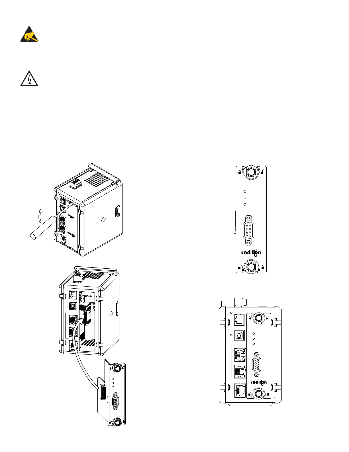
1. Remove power from the unit
2. Insert a flat-bladed screwdriver into the slot at the top of the expansion port
cover. Gently apply pressure on the screwdriver in an upward direction until
the expansion port cover disengages from the unit as shown in Figure 1.
3. Verify that the option card knobs are in the "unlocked" position as shown in
Figure 2.
4. Carefully insert the option card into the expansion port opening while
aligning the card-edge connector on the option card with the main board's
header, as shown in Figure 3. Once aligned, gently press on the front of the
card until it is flush with the front of the case.
5. Turn the option card knobs to the locked position as shown in Figure 4.
XCPB
DP
WD
DATA
Figure 3
Figure 1
XCPB
DP
WD
DATA
Figure 2
XCPB
DP
WD
DATA
Figure 4
2
Page 3

POWER SUPPLY REQUIREMENTS
NEW AND EXISTING INSTALLATIONS
The XCPB option card draws all of its power from the main board of the
Modular Controller master or Data Station Plus. The specifications of the
Modular Controller master or Data Station Plus account for the power needs of
an option card.
COMMUNICATING WITH THE XCPB OPTION CARD
CONFIGURING THE XCPB OPTION CARD
The XCPB is configured using Crimson® software. Crimson is available as a
free download from www.redlion.net, or it can be ordered on CD. Updates to
Crimson for new features and drivers are posted on the website as they become
available. By configuring the XCPB using the latest version of Crimson, you are
assured that your unit has the most up-to-date feature set. Additional information
can be found in your hardware bulletin and also in the Crimson 2.0 user manual.
To enable the option card, click on the left hand pane of the Communications
window in Crimson 2.0 and highlight the icon that represents the master or Data
Station Plus. In the right pane, click the Option Card Selection’s Edit button to
show the selection dialog, and choose the PROFIBUS option card from the list.
The PROFIBUS option card will then appear in the left hand pane, installed in
the tree of available ports.
CONFIGURING THE DRIVER
To select a driver, click on the left hand pane of the Communications window
and highlight the PROFIBUS Interface icon. In the right hand pane, click the
Driver Selection Edit button to show the Driver Selection dialog and select the
PROFIBUS DP driver from the list.
The Station Address of the PROFIBUS node is the only property that needs
to be configured. This should be a unique address on the PROFIBUS Network
in the range 1..125.
SOFTWARE/UNIT OPERATION
LEDS
The card has 3 LEDs visible on the front of the option card that provide status
information, described in Table 1.
DATA (Red) WD (Green) DP (Red) DESCRIPTION
OFF Baud Search
OFF OFF ON Baud Control
OFF SLOW FLASH FAST FLASH
OFF FAST FLASH SLOW FLASH
ON OFF OFF Data Exchange
CRIMSON® SOFTWARE
Crimson 2.0 software is available as a free download from www.redlion.net
or it can be purchased on a CD, see “Ordering Information” for part number.
The latest version of the software is always available from the web site, and
updating your copy is free.
TROUBLESHOOTING YOUR XCPB OPTION CARD
If for any reason you have trouble operating, connecting, or simply have
questions concerning your new XCPB option card, contact Red Lion’s technical
support. For contact information, refer to the back page of this bulletin for
phone and fax numbers.
EMAIL: techsupport@redlion.net
Web Site: http://www.redlion.net
SLOW ALTERNATING FLASH
Waiting for Parameter Telegram
Waiting for Configuration Telegram
CONFIGURING THE DATA TAGS
A PROFIBUS master exchanges data with slaves as separate input and output
blocks. Data transfer direction is described with respect to the PROFIBUS
Network such that input data is transferred to the network, or written by the
Modular Controller/Data Station Plus and output data is transferred from the
network or read by the Modular Controller/Data Station Plus. This is important
when it comes to configuring the data access for each tag mapped to a
PROFIBUS data block.
MAPPING TAGS TO PROFIBUS
PROFIBUS data blocks have no concept or knowledge of data type or
structure – they are described by a size in bytes. Crimson’s tag-based approach
to data allows for data of mixed type, bytes, 16-bit words, 32-bit words and
32-bit floating point numbers to be mapped into a single data block. To map a
data tag to a PROFIBUS data block, click in the left hand pane of the Data T ags
window, highlight the required Data Tag icon. In the right hand pane click the
Data Mapping button and select the PROFIBUS device to show the Select
Address for PROFIBUS DP dialog.
The Block Type defines whether the tag will be read from (Output Block) or
written to (Input Block) the PROFIBUS network
The Data Offset is the byte address of the Data Tag within the Data Block
The Data Type is the actual size in bytes of the data that will be mapped into
the Data Block.
CONFIGURING DATA ACCESS IN CRIMSON 2.0
As described, Data Tags are mapped to either an Input Block
and are Write only, or an Output Block and are Read Only. The
Access must be selected to reflect this.
3
Page 4

The Company warrants the products it manufactures against defects in materials and workmanship
LIMITED WARRANTY
for a period limited to two years from the date of shipment, provided the products have been stored,
handled, installed, and used under proper conditions. The Company’s liability under this limited
warranty shall extend only to the repair or replacement of a defective product, at The Company’s
option. The Company disclaims all liability for any affirmation, promise or representation with
respect to the products.
The customer agrees to hold Red Lion Controls harmless from, defend, and indemnify RLC against
damages, claims, and expenses arising out of subsequent sales of RLC products or products
containing components manufactured by RLC and based upon personal injuries, deaths, property
damage, lost profits, and other matters which Buyer, its employees, or sub-contractors are or may be
to any extent liable, including without limitation penalties imposed by the Consumer Product Safety
Act (P.L. 92-573) and liability imposed upon any person pursuant to the Magnuson-Moss Warranty
Act (P.L. 93-637), as now in effect or as amended hereafter.
No warranties expressed or implied are created with respect to The Company’s products except those
expressly contained herein. The Customer acknowledges the disclaimers and limitations contained
herein and relies on no other warranties or affirmations.
Red Lion Controls
Headquarters
20 Willow Springs Circle
York PA 17406
Tel +1 (717) 767-6511
Fax +1 (717) 764-0839
Red Lion Controls
Europe
Printerweg 10
NL - 3821 AD Amersfoort
Tel +31 (0) 334 723 225
Fax +31 (0) 334 893 793
Red Lion Controls
India
54, Vishvas Tenement
GST Road, New Ranip,
Ahmedabad-382480 Gujarat, India
Tel +91 987 954 0503
Fax +91 79 275 31 350
Red Lion Controls
China
Unit 101, XinAn Plaza
Building 13, No.99 Tianzhou Road
ShangHai, P.R. China 200223
Tel +86 21 6113-3688
Fax +86 21 6113-3683
 Loading...