

Page 1
7
8
9
10
11
12
6
5
4
3
2
1
2.37 (60.2)
1.77
(45.0)
SOCKET P/N 2300200
(ORDER SEPARATELY)
.88
(22.4)
4.44
(112.8)
* RANGE ADJUSTMENT (VOLTAGE & CURRENT OUTPUT)
.84
(21.3)
2.69
(68.3)
2.31 (58.7)
.84
(21.3)
SOCKET
P/N 2300200
.16 (4.1) DIA.
2 HOLES
* ZERO ADJUSTMENT (CURRENT OUTPUT ONLY)
* 20 TURN SCREWDRIVER
ADJUSTMENTS ACCESSIBLE
THROUGH TOP
Tel +1 (717) 767-6511
Fax +1 (717) 764-0839
www.redlion.net
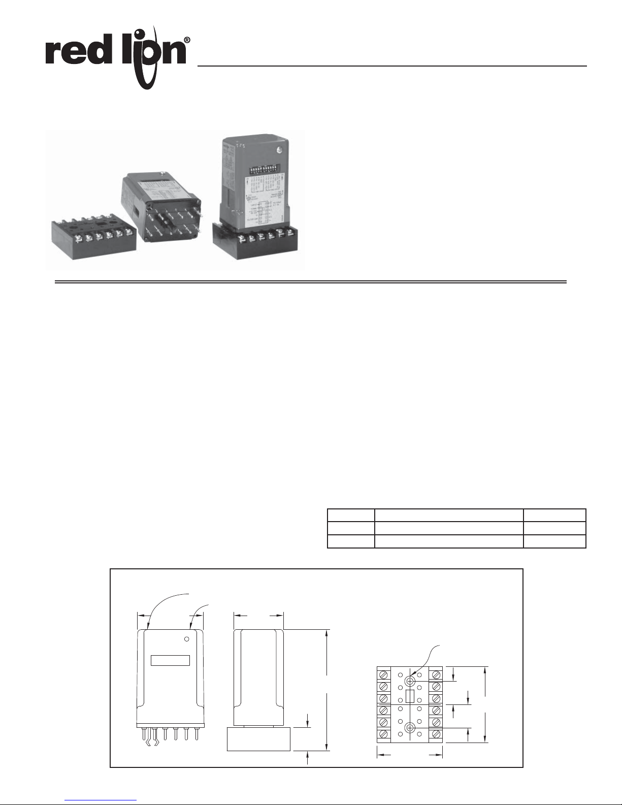
MODEL PRA2 - PULSE RATE TO ANALOG CONVERTER
DELIVERS ANALOG OUTPUT PROPORTIONAL TO INPUT
PULSE-RATE (FREQUENCY)
ACCEPTS VARIABLE PULSE-RATE INPUTS FROM A WIDE
VARIETY OF SENSORS
DUAL SIGNAL OUTPUT, 0 TO 10 VDC PLUS SELECTABLE
SIGNAL CURRENT OUTPUT OF 0 TO 1 MA OR 4 TO 20 MA
SELECTABLE FREQUENCY RANGE RATINGS FROM 30 HZ TO
10 KHZ
ACCURACY (LINEARITY) 0.25%
SWITCH SELECTABLE FOR 115 OR 230 VAC
Bulletin No. PRA2-C
Drawing No. LP0540
Released 10/12
DESCRIPTION
The Model PRA2 is a convenient plug-in module that provides voltage and
current analog output signals proportional to the pulse-rate (frequency) of the
input signal. In typical applications the PRA2 input is supplied by a machine
mounted sensor that generates a signal which has a frequency proportional to
machine or process speed. The PRA2 converts the frequency content of this
signal to analog form for operating chart recorders, supplying speed control
signals, or driving other controls and indicators that require analog input.
The PRA2 develops an internal “constant-area” pulse from the negative
going edge of each input pulse or wave form cycle. These “Constant-area”
pulses are fixed in voltage amplitude and time duration. The PRA2 then takes
the average of a train of these pulses to generate an output voltage level
proportional to the frequency. Another circuit within the PRA2 monitors the
voltage output and produces a current output signal that will deliver either 0 to
1 or 4 to 20 mA, as determined by a set-up switch.
This unit is available with five overlapping adjustable range ratings, each
rating providing a calibration adjustment to deliver maximum output over an
input frequency range of approximately 3.3:1. Since the PRA2 develops an
output by averaging pulses, an inherent response time is involved (See response
table, next page). The minimum response time is fixed for each range rating. It
is longest for the lowest range rating and decreases as the frequency range rating
increases. Response time must be considered, when using the PRA2 to provide
closed-loop speed feedback signals, to avoid stability problems. For speed
feedback applications it is usually advisable to select a high frequency range
coupled with an appropriate sensor arrangement that delivers a high pulse rate.
The internal output filtering supplied for averaging purposes is kept to a
minimum to provide the fastest practical response time for each range rating.
Extra external capacitance can be added to provide more filtering if required.
DIMENSIONS In inches (mm)
The plug-in module mates with a heavy duty, CSA approved base mounting
socket with pressure clamp screw terminals that accept stripped wires without lugs.
SPECIFICATIONS
1. PRIMARY SUPPLY VOLTAGE: Switch selectable for 115 or 230 VAC
±10%, 60 Hz; 8 VA
2. SENSOR OUTPUT POWER: +12 VDC ±5% regulated, 60 mA max.
3. SIGNAL INPUT CHARACTERISTICS: See “Input & Output Switch
Set-up” section.
4. MAX. FREQUENCY ADJUSTMENT: 30 Hz to 10 KHz
5. SIGNAL VOLTAGE OUTPUT: 0 to 10 VDC @ 10 mA max.
6. SIGNAL CURRENT OUTPUT (Selectable):
0 to 1 mA into load resistance range 0 to 4 K.
4 to 20 mA into load resistance range 0 to 250
7. LINEARITY: ±0.25% of full range setting.
8. VOLTAGE/CURRENT OUTPUT TRACKING: Current Signals follow
voltage signals within ±3% of full range setting.
9. RESPONSE TIME: See table on next page.
10. OPERATING TEMPERATURE RANGE: 0 to 60
o
C.
11. WEIGHT: PRA2 - 8 oz (226.8 g); Mating 12-Pin Socket - 2 oz (56.7 g).
ORDERING INFORMATION
MODEL NO. DESCRIPTION PART NUMBERS
PRA2 Pulse Rate to Analog Converter PRA20000
Socket, 12-Pin 2300200
1
Page 2
7
8
9
10
11
12 1
2
3
4
5
6
INPUT
N.C.
COMM.
+12V
TO
SENSOR
A.C.
POWER
(SEE PG. 3)
0-10 VDC
AT 10MA MAX.
OUTPUT
OPTIONAL
FILTER CAP
(-)
(+)
CURRENT
OUTPUT
0-1MA, MAX. R = 4K
4-20MA, MAX. R = 250Ω
L
L
R
L
COMM. COMM.
N.C.
(-)
APPLICATION CONSIDERATIONS
OVERRANGE
OUTPUT SATUATION
OUTPUT CURRENT 4-20MA
OUTPUT CURRENT 0-1MA
OUTPUT VOLTS
LINEAR REGION
0123456
4
0
12
.5
20
1
510
ADJUSTABLE
RANGE
FREQUENCY KHZ
TRANSFER CHARACTERISTICS
FOR RANGE 4
(FULL SCALE ADJUSTMENT
RANGE, 1 - 3 KHZ)
FULL SCALE OUTPUT
MINIMUM RANGE
MAXIMUM RANGE
10% 20% 40% 60%
0
1
2
% OF FULL SCALE OUTPUT
3
80% 100%
TYPICAL OUTPUT RIPPLE
(SEE TABLE FOR CURVE KEY
TO PARTICULAR PRA2 RANGE)
MIN. FULL SCALE ADJUSTMENT
MAX. FULL SCALE ADJUSTMENT
PEAK TO PEAK RIPPLE VOLTS
A
B
C
C
B
A
0
3456
43 65
43 65
43 65
43 65
12
12
12
12
21
21 43
12 346556
21 43 65
12 34
21 43
56
65
ON ON
**
**
**
**
**
**
**
**
**
**
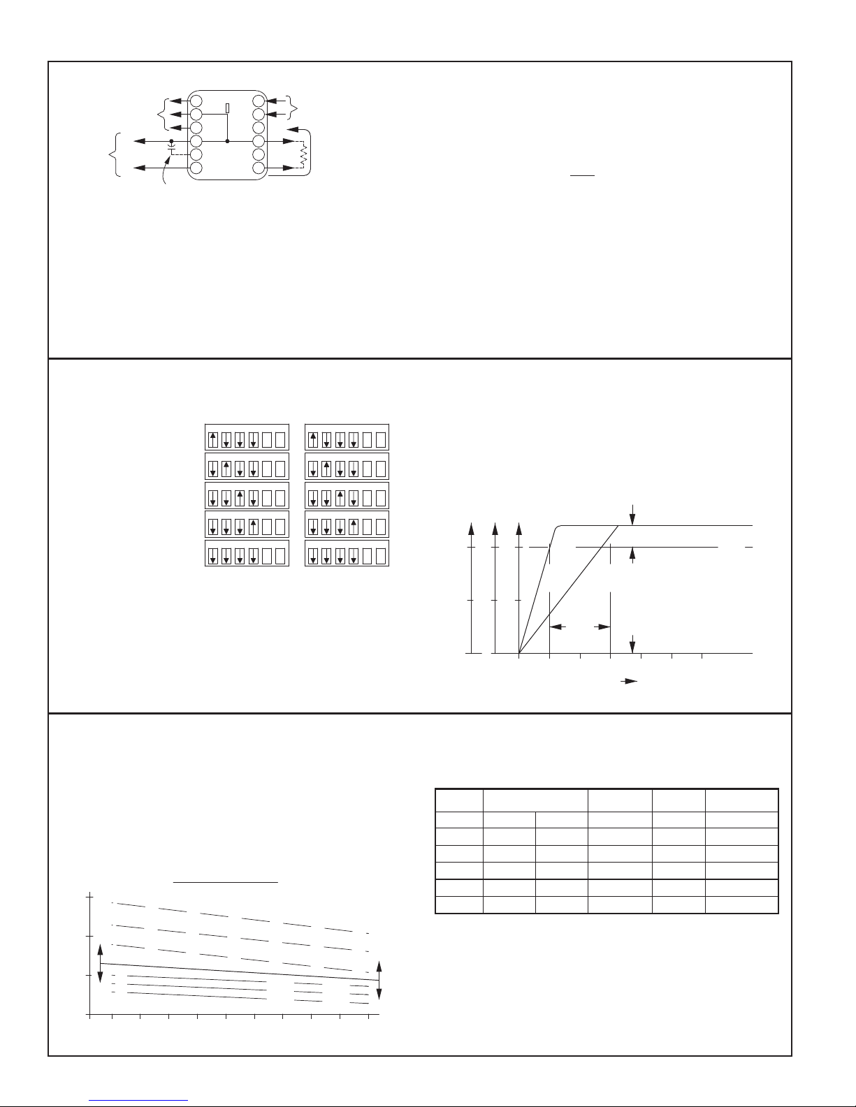
CONNECTIONS & SET-UP ADJUSTMENTS
+
(+)
VOLTAGE OUTPUT ADJUSTMENT:
Only the RANGE ADJUSTMENT is effective when voltage output is used.
(Zero Adjustment affects only current output.)
PROCEDURE
1. Set AC power switch to proper position.
2. Connect voltmeter to Terminals 10 & 12.
3. Set the Range Switches for desired max. input frequency.
4. Apply the maximum input frequency and turn the *RANGE
ADJUSTMENT to obtain the desired output voltage.
ADJUSTABLE RANGE RATINGS & OVER RANGE OPERATION
Frequency Range
RANGE
FULL SCALE
ADJUSTMENT
1 30 Hz to 100 Hz
2 100 Hz to 300 Hz
3 300 Hz to 1 kHz
SW1
SW2
CURRENT OUTPUT ADJUSTMENTS:
When current output is used, the ZERO ADJUSTMENT must be set before
RANGE ADJUSTMENT setting is attempted.
PROCEDURE
1. Set AC power switch to proper position.
2. Select current range with switch SW2-6 (OFF 0-1 mA / ON 4-20 mA) .
3. Connect a milliammeter in series with the current loop circuit from Term 1
to Term 3. CAUTION: DO NOT exceed maximum load resistance specified
for the current range.
4. Set the Range Switches for desired max. input frequency.
5. Zero Adjustment:
A) 0-1 mA Range - With input signal removed (zero frequency) turn ZERO
B) 4-20 mA Range - Set ZERO ADJUST until current is 4 mA.
6. *Range Adjustment: Apply maximum frequency input signal and set
RANGE ADJUSTMENT to get desired output.
* RANGE ADJUSTMENT - Turning CW decreases output at a given frequency
(increases range) and turning CCW increases output (decreases range).
and the output voltage or current will be proportional to input frequency. If the
input frequency exceeds the full-scale range setting (over range), the output
will flatten out and saturate at some level above 10 V at all higher frequencies.
CAUTION: Maximum input frequency for PRA2 modules is 10 KHz. At input
frequencies in excess of 10 KHz, the frequency roll-off characteristics of the
input circuit will cause signal dropout and result in discontinuous
operation.
ADJUST CW until positive current flow is indicated. Then, turn back
CCW until the current flow just reaches zero. Stop turning the adjustment
at that point.
4 1 kHz to 3 kHz
5 3 kHz to 10 kHz
Frequency Curves
The Transfer Curve (at right) shows the frequency-input/voltage-output
relationship for the PRA2, Range #4 for both Min. Range (0-1 KHz) and Max.
Range (0-3 KHz) adjustment. These curves are typical and apply to all PRA2
ranges.
As shown by these curves, the PRA2 RANGE ADJUSTMENT allows the
unit to be calibrated to deliver full scale output for any input frequency from
the min. to max. range ratings. As long as the input frequency is equal-to or
less-than the full-scale range setting, the PRA2 is operating in its linear region
OUTPUT RESPONSE & RIPPLE CHARACTERISTICS
PRA2 Modules are supplied with a minimum amount of output ripple
filtering in order to avoid compromising response-time. The data presented
below, permits a reasonable estimate of the amount of ripple and the responsetime that will be experienced in a particular application. As shown by the
curves below, the amount of output ripple depends on the range setting and the
input frequency.
Ripple voltage can be reduced by adding external filter capacitance, but
ripple-reduction is a trade-off against increased response times. This must be
kept in mind, especially if the PRA2 is to be used to supply feedback control
signals.
The values of capacitance given in the table are for reference only and do
not imply a limit to the amount of capacitance that can be added. For example,
an external filter capacitance may be 10 times the reference values shown for
a very high degree of ripple reduction, provided that the resulting long
response time is acceptable.
RANGE
FULL SCALE RANGE
ADJUSTMENT
MIN MAX [1] [2] [3]
1 30 Hz 100 Hz 250 msec A 2.2 mfd
2 100 Hz 300 Hz 75 msec A 0.56 mfd
3 0.3 KHz 1 KHz 25 msec A 0.22 mfd
4 1 KHz 3 KHz 10 msec B 0.1 mfd
5 3 KHz 10 KHz 8 msec C 0.047 mfd
RESPONSE
TIME
RIPPLE
CURVE
EXT CAP (REF)
Note: If large capacitor values are required to achieve a high degree of ripple
reduction, tantalum capacitors rated at 35 V or more are recommended.
(Proper polarity must be observed. See Connection Drawing above.)
[1] RESPONSE TIME - Time required for the output to reach 90% of final value
when the frequency is instantly changed from 0 to full-scale range frequency.
[2] See “Typical Output Ripple” Curves (at left).
[3] External Capacitance can be added between terminals 10 and 11 to decrease
ripple. Reference values shown in MFD, will reduce ripple approximately 50%
and will roughly double response times.
2
Page 3

INPUT & OUTPUT SWITCH SET-UP
825K
39K10K3.4K
37.4K
3.9K1K
8
*BLK COMM.
470pf
0.1
S1-6S1-5
7
*WHT
9
*REDIN+12V
INPUT AMP.
SCHMIDT TRIG.
CONNECTED
SENSOR
POWER
SIGNAL
INPUT
*STD. RLC 3-WIRE
COLOR CODE
SENSOR CONNECTIONS
INPUT
CONFIG.
SWITCHES
S2-5
SNK.
SRC.
LOGIC
5
6*6
5
ON
SW1
SW2
0-1/4-20
7
8
9
INPUT
COMM.
+12V
PRA2
MAGNETIC PICKUP
SHIELD
LOGIC
SRC.
SNK.
55
66
*
SW1
SW2
7
8
9
INPUT
COMM.
+12V
PRA2
SENSOR
PNP O.C.
OUTPUT
+12V
OUTPUT
COMMON
ON
LOGIC
SRC.
SNK.
55
66
*
SW2
SW1
7
8
9
INPUT
COMM.
+12V
PRA2
SENSOR
NPN O.C.
OUTPUT
RED
WHT
BLK
ON
LOGIC
SRC.
SNK.
55
66
*
SW2
SW1
7
8
9
INPUT
COMM.
+12V
PRA2
RLC
SENSOR
BLU
BLK OR BRN
MODELS
PSA-1
PSA-2
ON
LOGIC
SRC.
SNK.
55
66
*
SW2
SW1
7
8
9
INPUT
COMM.
+12V
PRA2
R
C
LOGIC
SRC.
SNK.
55
66
*
SW2
SW1
7
8
9
INPUT
COMM.
+12V
PRA2
SENSOR
-EF
OUTPUT
A
C
B
ON
LOGIC
SRC.
SNK.
55
66
*
SW2
SW1
7
8
9
INPUT
COMM.
+12V
PRA2
+V
ON
SNK.
LOGIC
SRC.
565
6
*
SW2
SW1
The Model PRA2 Pulse-Rate to Analog Converter uses the circuit shown on
the right. The circuit uses a comparator amplifier connected as a Schmidt trigger
circuit to convert the input wave form into the pulse form required for proper
circuit operation. Three set-up switches are used to configure the input circuit
to accept signals from a wide variety of sources, as follows:
SW1-5 - ON: Connects a 3.9 K pull-up resistor for sensors with current sinking
output. (Maximum sensor current is 3 mA.)
SW2-5 - ON: Connects a 1 K pull-down resistor for sensors with sourcing
output. (Maximum sensor output current is 12 mA @ 12 V output.)
SW1-6 - ON: Sets bias of input to trigger at V
level signals.
OFF: Sets the bias of input to trigger at V
increased sensitivity when used with magnetic pickups.
= 2.5 V, VIH = 3.0 V; for logic
IL
= 0.25 V, VIH = 0.75 V; for
IL
SW2-6 - ON: 4-20 mA Output
OFF: 0-1 mA Output
Paralleling With a Counter and/or Rate Indicator Inputs: The PRA2 can be
OTHER CHARACTERISTICS & SPECIFICATIONS
Maximum Operating Frequency: 10 KHz with minimum pulse width ON and
OFF times of 50 μsec.
Maximum Input V oltage: Pin 7 (Input) may be driven from an external voltage
up to ±90V provided SW2-5 and SW1-5 are “OFF” to disconnect internal
load resistors. (Maximum Input Voltage with SW2-5 “ON” is ±24 V)
Input Impedance: With SW2-5 and SW1-5 “OFF”, the resistive input
impedance exceeds 1 Megohm, as long as Pin 7 voltage is greater than zero
and less than +12 V.
operated from a common sensor with current sinking output that is also used
to drive the input of a Counter or Rate Indicator. Connect Pin 8 to the
Common Terminal and Pin 7 to the Input Terminal of the Counter or Rate
Indicator; set SW2-5 and SW1-5 “OFF” and SW1-6 “ON”. DO NOT
PARALLEL CONNECT THE +12V OUTPUT (Pin 9) OF PRA2 UNITS
WITH THE +12V OUTPUTS OF COUNTERS, DITAKS, OR OTHER
PRS1, or PRA2 UNITS. These units have regulated supplies that will not
load-share. Multiple inputs cannot be operated from sensing switches, 2-wire
proximity sensors, or magnetic pickups.
CONNECTIONS & CONFIGURATION SWITCH SET-UP FOR VARIOUS SENSOR OUTPUTS
MAGNETIC PICKUPS
RECOMMENDED RULES FOR MAGNETIC PICKUP CONNECTIONS
1. Mount the PRA2 in a relatively “noise-free” environment, away from motor starters,
control relays, or other sources of electrical interference.
2. Use 2-wire shielded cable for magnetic pickup signal leads.
3. Never run signal cable in conduit, troughs, or cable bundles with power carrying
conductors.
4. Connect the shield to the common Terminal “8” at the input of the PRA2. DO NOT
connect the shield at the pickup end, leave it “open” and insulate the exposed shield to
prevent electrical contact with the frame or case. (Shielded cable, supplied on some
RLC magnetic pickups, has open shield on pickup end.)
2-WIRE PROXIMITY SENSORS A.C. INPUTS FROM INVERTERS, A.C.
INPUT FROM CMOS OR TTL
ON
TACHOMETERS GENERATORS, ETC.
R - Resistor to limit input current to 5 mA peak
C - Filter cap required when input A.C. has “ringing”
characteristics as with inverters.
A.C. Power sources exceeding 50 V output
should be coupled with an isolation transformer.
3
SENSORS WITH CURRENT SINK OUTPUT (NPN O.C.)
RLC SENSOR MODELS:
ASTC, LMPC, PSAC, ZFG, ZCG, ZBG, ZHG, ZCH, HESS, etc.
SENSORS WITH CURRENT SOURCE OUTPUT (PNP O.C.)
OLDER STYLE RLC SENSORS WITH
-EF OUTPUT
ON
RLC SENSOR MODEL: LMPEC
Page 4

SENSOR & FREQUENCY RANGE SELECTION
7
8
9
INPUT
COMM.
+12V
PRA2
MODEL
RRDC
SRC.
LOGIC
SNK.
ON
WHT
BLUE
BRN
*
SW2
SW1
55
66
The PRA2 Pulse-Rate to Analog Converter normally operates from a
variable frequency signal supplied by a machine mounted sensor. The sensor
signal varies in frequency in direct proportion to machine speed, and may be a
sinusoidal, triangular, square, or pulse-type waveform. The sensor arrangement
can take a variety of forms such as a Magnetic Pickup or Proximity Sensor
detecting passing teeth on a sprocket or gear, a Photo-Electric Scanner viewing
passing pulley spokes, a Rotary Pulse Generator coupled to a machine shaft, or
a Length Sensor driven by a web or ribbon of material passing through the
machine. (See Sensor Section of the catalog for more information on sensors.)
Since the PRA2 operates from the frequency content of the incoming signal,
the response time of this device is also related to the signal frequency. This
gives rise to the cardinal rule of selecting a sensor arrangement:
WHEN RESPONSE TIME IS IMPORTANT, SELECT A SENSOR
ARRANGEMENT & LOCATION THAT WILL PROVIDE A HIGH
FREQUENCY OUTPUT AT OPERATING SPEED.
When a PRA2 application is first contemplated, it seems to be natural to
think in terms of applying the sensor to the low speed end of the power drive
train. In some cases this may be the only practical location for the sensor, and
if fast response is needed from the PRA2, a sensor arrangement capable of
delivering a high number of cycles or pulses/revolution (PPR) will be required.
In a great number of applications however, generating a higher frequency
sensor signal is simply a matter of locating the sensor on a intermediate or high
speed shaft such as directly on the drive motor shaft.
Another advantage of moving the sensor location up toward the high speed
end of the drive train is that the shaft rotary motion is usually much smoother
and more regular. Slow speed shafts will often rotate irregularly due to gear
backlash, “slop” in couplings, or slack in chain drives.
SELECTING AN APPROPRIA TE SENSOR ARRANGEMENT
There are no exact rules governing the selection of a sensor arrangement
since machine geometry and conditions can vary widely from one application
to the next. However, the following generalized criteria will prove useful as
guidelines toward selecting the best sensor arrangement. (See Sensor Section of
the catalog for more information.)
ULTRA-LOW SHAFT SPEEDS (10RPM or less) - Proximity Sensors,
Photo-Electric Scanners, or Rotary Pulse Generators, are usually the best
selections. In most ultra-low speed applications, it is advisable to provide as
many pulses per revolution as possible (high PPR) to get acceptable
response times.
LOW-SHAFT SPEEDS (10-100RPM) - LMPC (Super-Sensitive Magnetic
Pickup), Proximity Sensors, Photo-Electric Scanners and RPG’s can usually
be applied in this speed range.
INTERMEDIATE SHAFT SPEEDS (10-1000RPM) - Magnetic Pickups,
the LMPC, RPG’s and some Proximity Sensors are appropriate at these
speeds.
HIGH-SHAFT SPEEDS (1000RPM and up) - Magnetic Pickups, the LMPC
and RPG’s are usually the best choices.
FOR LINEAR SPEEDS ON PAPER WEBS, TEXTILE, RIBBON, STRIP
AND WIRE - The LSC Length Sensor may prove desirable.
CAUTION: When selecting a sensor for operation at any speed, make sure the
sensor is also capable of delivering an output for the entire speed range up
through maximum machine speed.
DETERMINING SENSOR FREQUENCY OUTPUT &
SELECTING THE PROPER FREQUENCY RANGE
Machine speeds are normally expressed in revolutions/minute (RPM) while
the PRA2 has adjustable frequency ranges in cycles/second or Hz. In addition,
sensor arrangements usually deliver a number of signal cycles or pulses for
each shaft revolution. The following formula provides a convenient way to
relate these variables:
FRQ (CPS or Hz) =
RPM x PPR
60
WHERE:
RPM is the speed of the shaft where the sensor is located in revolutions per
minute.
PPR is the number of pulses (or cycles) produced by the sensor for one shaft
revolution.
EXAMPLE 1
A pulley with 6 spokes operates at 650 RPM maximum machine speed.
The spokes are to be sensed with a Model RR Retro-Reflective Photo Sensor.
The application requires a PRA2 to develop a 4-20 mA signal for a chart
recorder (20 mA output at max. speed). What is the frequency range to be
used for the PRA2?
FRQ @ max. speed =
650 RPM x 6 PPR
60
= 65 Hz
SELECT: Range 1 (adjustable for max. output 30 to 100 Hz)
EXAMPLE 2
The speed of a gravity-powered conveyor is restrained and controlled by
a hydraulic brake (pump) which is coupled to a conveyor shaft. A PRA2 is to
be used to supply a speed feed-back signal to the hydraulic control circuit,
with 0-10 VDC corresponding to a speed range of 0-36 RPM on the conveyor
shaft.
SOLUTION: Since the PRA2 is in the speed feed back control loop, fast
response is important and a high PPR will be needed to minimize delay in
output response. By using a 600 PPR Rotary Pulse Generator (ZBG)
coupled by 3:1 speed-increasing instrument belt drive, the effective PPR
of the conveyor shaft is 3 x 600 or 1800 PPR. The PRA2 input frequency
then is:
SELECT: Range 4 (adjustable for max. output, 1 to 3 KHz)
Note: The smoothness of shaft motion can be a factor in this type of
application. Direct coupling a high PPR Rotary Pulse Generator to a slow
moving shaft that dithers or exhibits rotary oscillation can create false
pulses reflected as an output that is erroneously high. A belt drive was
chosen here to help dampen vibration effects. Adding some additional
mass to the RPG shaft, such as a weighted drive pulley, will increase the
inertia and dampen oscillation even further.
36 RPM (max. speed) x 1800 PPR
FRQ =
60
= 1080 Hz
The Company warrants the products it manufactures against defects in materials and workmanship for a period limited to two years
from the date of shipment, provided the products have been stored, handled, installed, and used under proper conditions. The
Company’s liability under this limited warranty shall extend only to the repair or replacement of a defective product, at The
Company’s option. The Company disclaims all liability for any affirmation, promise or representation with respect to the products.
The customer agrees to hold Red Lion Controls harmless from, defend, and indemnify RLC against damages, claims, and expenses
arising out of subsequent sales of RLC products or products containing components manufactured by RLC and based upon personal
injuries, deaths, property damage, lost profits, and other matters which Buyer, its employees, or sub-contractors are or may be to any
extent liable, including without limitation penalties imposed by the Consumer Product Safety Act (P.L. 92-573) and liability imposed
upon any person pursuant to the Magnuson-Moss Warranty Act (P.L. 93-637), as now in effect or as amended hereafter.
No warranties expressed or implied are created with respect to The Company’s products except those expressly contained herein. The
Customer acknowledges the disclaimers and limitations contained herein and relies on no other warranties or affirmations.
LIMITED WARRANTY
 Loading...