

Page 1

THE PROCESS CONTROL UNIT
MODEL PCU INSTRUCTION MANUAL
Page 2

INTRODUCTION
C
US LISTED
The Process Control Unit (PCU) is a multi-purpose series of industrial
control products that are field-programmable for solving various
applications. This series of products is built around the concept that the end
user has the capability to program different personalities and functions into
the unit in order to adapt to different indication and control requirements.
The PCU unit, which you have purchased, has the same high quality
workmanship and advanced technological capabilities that have made Red
Lion Controls the leader in today’s industrial market.
Red Lion Controls has a complete line of industrial indication and control
equipment, and we look forward to servicing you now and in the future.
U
R
C
US LISTED
L
IND. CONT. EQ.
51EB
CAUTION: Read complete
instructions prior to installation
and operation of the unit.
CAUTION: Risk of electric shock.
Page 3

Table of Contents
GENERAL DESCRIPTION ....................................................................1
Safety Summary ............................................................................2
INSTALLATION & CONNECTIONS ...........................................................3
Installation Environment .....................................................................3
Standard Unit Installation ....................................................................3
NEMA 4X/IP65 Unit Installation ..............................................................3
Unit Removal Procedure .....................................................................5
Removing Bezel Assembly ..................................................................5
Installing Bezel Assembly ...................................................................5
Output Modules ............................................................................5
Output Module Restrictions ...............................................................5
Installing Output Modules ................................................................6
Typical Connections .....................................................................6
Select AC Power (115/230 VAC) .............................................................6
EMC Installation Guidelines .................................................................7
Wiring Connections ........................................................................8
Valve Positioner Wiring .................................................................9
Linear DC Output Wiring .................................................................9
Second Analog Input Wiring ..............................................................9
Program Disable Or User Input Wiring ....................................................10
AC Power Wiring ......................................................................10
FRONT PANEL DESCRIPTION ..............................................................11
Button Functions ..........................................................................11
OPERATION OVERVIEW ...................................................................12
Controller Power-up .......................................................................12
Controller Power Down ....................................................................12
Process Start-up ...........................................................................12
Manual (User) & Automatic Operation .......................................................12
Remote And Local Setpoint Operation ........................................................13
i
Page 4

Configuration Of Parameters ................................................................14
Parameter Entry ...........................................................................15
Normal Display Mode ......................................................................15
Modifying A Secondary Display Parameter From The Front Panel .................................15
UNPROTECTED PARAMETER MODE .......................................................16
Unprotected Parameter Mode Reference Table .................................................16
PROTECTED PARAMETER MODE ..........................................................18
Protected Parameter Mode Reference Table ....................................................18
FRONT PANEL PROGRAM DISABLE .......................................................19
Models With User Input ....................................................................19
Models With Program Disable ...............................................................19
HIDDEN FUNCTION MODE .................................................................20
Hidden Function Mode Reference Table .......................................................20
CONFIGURATION PARAMETER MODULES .................................................21
Input Module (1- In) .......................................................................21
Input Type (tYPE) ......................................................................21
Square Root Linearization (root) (Optional) ................................................21
Decimal Point Position (dCPt) ............................................................21
Rounding Increment ( rnd) ...............................................................21
Input Signal Filter and Display Update Rate (FLtr) ..........................................22
Scaling Points .........................................................................22
Display Values (dSP1 & dSP2) ...........................................................22
Signal Input Values (INP1 & INP2) .......................................................22
Key-in Method ....................................................................22
Signal Input Method ...............................................................22
Setpoint Limit Values (SPLO & SPHI) ....................................................23
Setpoint Ramp Rate (SPrP) ..............................................................23
Output Module (2-OP) .....................................................................24
Time Proportioning Cycle Time (CYCt) ...................................................24
Output Control Action (OPAC) ...........................................................24
Output Power Limits (OPLO & OPHI) .....................................................25
ii
Page 5

Input Overdrive Preset Power (OPFL) .....................................................25
Output Power Dampening (OPdP) ........................................................25
ON/OFF Control Hysteresis Band (CHYS) .................................................25
Auto-Tune Dampening Code (tcod) .......................................................26
Linear DC Analog Output (ANAS, ANLO, ANHI, ANdb, ANUt) (Optional) ....................26
Lockouts Module (3-LC) ...................................................................27
Lower Display Lockouts (SP, OP, IN-2, dEv, bdSP) .........................................27
Protected Mode Lockouts (Code, PID, PID2, rtbS & AL) .....................................28
Hidden Mode Lockouts (ALrS, trnF, tUNE and SPSL) .......................................28
Alarm Module (4-AL) (Optional) ............................................................28
Alarm Action (Act1, Act2) ..............................................................28
Second Analog Input Alarm ..............................................................29
Valve Fail Alarm (VFAL) ...............................................................29
Alarm Action Figures ...................................................................30
Alarm Reset (rSt1, rSt2) .................................................................32
Alarm Standby Delay (Stb1, Stb2) ........................................................32
Alarm Value (AL-1, AL-2) ..............................................................32
Alarm Hysteresis (AHYS) ...............................................................33
Secondary Output Module (5-02) (Optional) ...................................................33
Time Proportioning Cycle Time (CYC2) ...................................................33
Relative Gain (GAN2) ..................................................................33
Overlap/Deadband (db-2) ................................................................33
Serial Communications Module (6-SC) (Optional) ..............................................34
Baud Rate (bAUd) ......................................................................34
Parity Bit (PArb) .......................................................................34
Address Number (Addr) .................................................................34
Abbreviated or Full Transmission (Abrv) ...................................................34
Print Rate (PrAt) .......................................................................34
Print Options (PoPt) ....................................................................35
Second Analog Input Module (7-2N) (Optional) ................................................35
Operation mode (OPEr) .................................................................35
Square Root Linearization (root) ..........................................................35
iii
Page 6

Decimal Point Position (dPt2) ............................................................36
Second Analog Input Scaling Points (dSP1, INP1, dSP2, INP2) ................................36
Display Values (dSP1 & dSP2) ......................................................36
Signal Input Values (INP1 & INP2) .......................................................36
Key-in Method ....................................................................36
Signal Input Method ...............................................................36
Local/Remote Setpoint Transfer Modes (SPtr) ..............................................37
Secondary Output Power Dampening (OPd2) ...............................................37
Valve Positioner Module (8-VP) .............................................................37
Valve Position 1 And Valve Position 2 (VPS1, VPS2) ........................................37
Valve Update Time (VUdt) (Position And Velocity Mode) ....................................38
Valve Position Deadband (VPdb) (Position Mode) ...........................................38
Valve Fail Time Alarm (VFAL) (Position Mode) ............................................38
Valve Motor Open Time And Valve Motor Close Time (VOPt, VCLt) (Velocity mode) ............38
Valve Minimum On Time (VONt)(Velocity Mode) ..........................................38
Factory Service Operations Module (9-FS) ....................................................38
Reference Tables: Configuration Parameter Modules ............................................39
Configure Module 1 - Input Parameters (1-IN) ..............................................39
Configure Module 2 - Output Parameters (2-OP) ............................................40
Configure Module 3 - Lockout Parameters (3-LC) ...........................................41
Configure Module 4 - Alarms (4-AL) .....................................................42
Configure Module 5 - Secondary Output Parameters (5-O2) ...................................43
Configure Module 6 - Serial Communications (6-SC) ........................................44
Configure Module 7 - Second Analog Input (7-2N) ..........................................45
Configure Module 8 - Valve Positioner (8-VP) ..............................................45
Configure Module 9 - Factory Service Operations (9-FS) .....................................46
RS485 SERIAL COMMUNICATIONS INTERFACE ............................................47
Communication Format .....................................................................47
Sending Commands And Data ...............................................................47
Output Status ..........................................................................48
Receiving Data ...........................................................................50
Serial Connections .........................................................................52
iv
Page 7

Terminal Descriptions ...................................................................52
Connecting To A Host Terminal ..........................................................53
Troubleshooting Serial Communications ......................................................53
VALVE POSITION OPTION .................................................................54
Position Mode Valve Control ................................................................54
Velocity Mode Valve Control ...............................................................55
SECOND ANALOG INPUT OPTION ..........................................................56
Remote Setpoint ...........................................................................56
Flow Ratio Control .....................................................................56
Process Remote Setpoint Slave Control ....................................................56
Cascade Control ..........................................................................56
External Cascade Control ...............................................................57
Internal Cascade Control ................................................................58
PID CONTROL .............................................................................59
Proportional Band .........................................................................59
Integral Time .............................................................................59
Derivative Time ...........................................................................60
Output Power Offset (Manual Reset) .........................................................60
PID Adjustments ..........................................................................60
ON/OFF CONTROL .........................................................................62
AUTO-TUNE ................................................................................64
Initiate Auto-Tune .........................................................................65
Auto-Tune Of Secondary Output (OP2) / Main Output (OP1) Systems .............................65
Auto-Tune Of Internal Cascade Controllers ....................................................65
Auto-Tune Of External Cascade Systems (Remote Setpoint) ......................................66
APPENDIX “A” - APPLICATION EXAMPLES .................................................67
Chemical Mixing Application ...............................................................67
Flow Rate Programming Example ............................................................68
APPENDIX “B” - SPECIFICATIONS AND DIMENSIONS .......................................69
APPENDIX “C” - TROUBLESHOOTING ......................................................73
v
Page 8

Output Leakage Current ....................................................................75
APPENDIX “D” - MANUAL TUNING .........................................................76
Open Loop Step Response Method ...........................................................76
Closed Loop Cycling Method ................................................................77
APPENDIX “E” - CALIBRATION ............................................................78
Calibration Check .........................................................................78
Voltage Reading Check .....................................................................78
Current Reading Check .....................................................................78
Linear DC Output Check ...................................................................78
4to20mA ............................................................................78
0to10VDC ...........................................................................78
Second Input Check ........................................................................78
Second Analog Input Check ..............................................................78
Valve Positioner Check .................................................................78
Calibration ...............................................................................79
Configure Step 9 - Factory Service Operations (9-Fs) ........................................79
Voltage Calibration .....................................................................79
Current Calibration .....................................................................79
Analog Output Calibration (ANCL) .......................................................79
4to20mA .......................................................................79
0to10VDC ......................................................................79
Second Analog Input Calibration (2CAL) ..................................................80
Second Analog Input (Remote Setpoint) ...................................................80
Motorized Valve Positioner ..............................................................80
APPENDIX “F”-USER PARAMETER VALUE CHART .........................................81
APPENDIX “G” ORDERING INFORMATION ................................................84
vi
Page 9

GENERAL DESCRIPTION
The PCU Controlleraccepts eithera0to10VDCora4to20mADCinput
signal,precisely scales the process signalaccording to programmablescaling
points, and provides an accurate output control signal (time proportional,
linear,or valvepositioning) to maintain a process at thedesired controlpoint.
Acomprehensiveset ofeasyto use stepsallowsthe controller tosolve various
application requirements.
Thecontroller can operateinthe PID controlmode for boththe main output
and optional secondary output. On-demand auto-tune establishes the tuning
constants. The PID tuning constants may be fine-tuned by the operator at any
time and locked out from further modification. The controller employs a
unique overshoot suppression feature that allows the quickest response
without excessive overshoot. The unit can be transferred to operate in the
manual mode, providing the operator with direct control of the output. The
controller can also be programmed to operate in the ON/OFF control mode
with adjustable hysteresis.
Dual 4-digit displays allow viewing of the measured value and setpoint
simultaneously. Front panel indicators inform the operator of the controller
and output status. Replaceable and interchangeable output modules (Relay,
SSR Drive, or Triac) can be installed for the main control output, Alarm
output(s), Secondary output, and Valve Positioner outputs.
Optionaldual alarms canbe configured toactivate according toa variety of
actions (Absolute HI or LO, DeviationHI or LO, Band IN or OUT,and Valve
Fail Detect) with adjustable hysteresis. A standby feature suppresses the
output during power-up until the process stabilizes outside the alarm region.
An optional secondary output is available (for processes requiring cooling,
pH balance, etc.) that provides increased control accuracy and response.
A linear 4 to 20 mA or 0 to 10 VDC output signal is available to interface
with actuators, chart recorders, indicators, or other controllers. The type of
Linear DC output is determined by the model ordered. (See Ordering
Information, page 84, for available models.) The output signal can be
digitally scaled and selected to transmit one of the following: % output
power,measurement value deviationor setpoint value.For Linear DCcontrol
applications,the adjustable outputdemand dampening, outputdeadband, and
output update time parameters expand the versatility of the PCU to final
control devices.
Theoptional Motorized Valve Positioner directlycontrols theposition of a
valve by the use of twin outputs (open and close) to control the direction of
motor rotation. The motor position defines the opening position at the valve.
Two control modes are possible: position control, which makes use of the
slidewirefeedbacksignal supplied withthepositioner and velocitycontrol,in
whichno slidewirefeedback signalis used.Parameters areprovided toadjust
the operation of the valve. These include:
- Valve activity hysteresis
- Valve update time
- Variable control dampening
- Slidewire signal fail action
- Adjustable valve position limits
The Valve Positioner PCU achieves tight process control; yet minimizes
unnecessary valve activity. An alarm event output or display alarm can be
programmed under loss of slidewire feedback or under valve fail detection.
The optional Second Analog Input (0 to 20 mA DC) can be configured as a
Remote Setpoint signal or as a Secondary Process signal. Configuration of
the Second Analog Input as a Remote Setpoint signal allows ratio control,
master setpoint/multiple slave operation, and the ability to cascade the PCU
with another controller (External Cascade). Configuration of the Second
Input as a Secondary Process signal allows operation as a two-process
cascade controller within a single unit (Internal Cascade). In either control
mode,parameters are providedto scale, configure,communicate and monitor
the activity of both analog inputs. A square law linearizer function can be
used to linearize signals derived from flow transmitters.
The optional RS485 multi-drop serial communication interface provides
two-way communication between a PCU unit and other compatible
equipment such as a printer, a programmable controller, or a host computer.
In multi-point applications the address number of each unit on the line can be
programmed from zero to ninety-nine. Up to thirty-two units can be installed
ona single pair of wires.The Setpointvalue, % Output Power, SetpointRamp
Rate, etc. can be interrogated or changed, by sending the proper command
code via serial communications. Alarm output(s) may also be reset via the
serial communications interface option.
-1-
Page 10

A programmable User Input is available with RS485, Valve Position, and
Second Analog Input models. The User Input can be programmed to perform
a variety of controller functions.
An optional NEMA 4X/IP65 rated bezel is available for wash down
applications and similar environments, when properly installed. Modern
surface-mount technology, in-house assembly and testing, and high
immunity to noise interference makes the controller extremely reliable in
industrial environments.
SAFETY SUMMARY
All safety related regulations, local codes and instructions that appear in
themanual or on equipment mustbe observed toensure personalsafety and to
prevent damage to either the instrument or equipment connected to it. If
equipment is used in a manner not specified by the manufacturer, the
protection provided by the equipment may be impaired.
Donot usethe PCUto directlycommand motors, valves, or other actuators
notequipped withsafeguards. Todo so,can bepotentially harmfulto persons
orequipment in the event of a faultto the unit. An independent and redundant
temperaturelimit indicator withalarm outputsis strongly recommended.Red
LionControls offersvarious units (such as an IMP, IMD1, or IMD2)that may
be used for this purpose. The indicators should have input sensors and AC
power feeds independent from other equipment.
-2-
Page 11

INST ALLA TION& CONNECTIONS
INSTALLATION ENVIRONMENT
Theunitshould be installedin a locationthatdoes not exceedthemaximum
operatingtemperature and providesgood air circulation.Placing the unitnear
devices that generate excessive heat should be avoided.
Continuousexposure to directsunlight mayaccelerate the agingprocess of
the bezel.
Thebezelshould be cleanedonly with asoftcloth and neutralsoapproduct.
Do not use solvents.
Do not use tools of any kind (screwdrivers, pens, pencils, etc.) to operate
the keypad of the unit.
STANDARD UNIT INSTALLATION
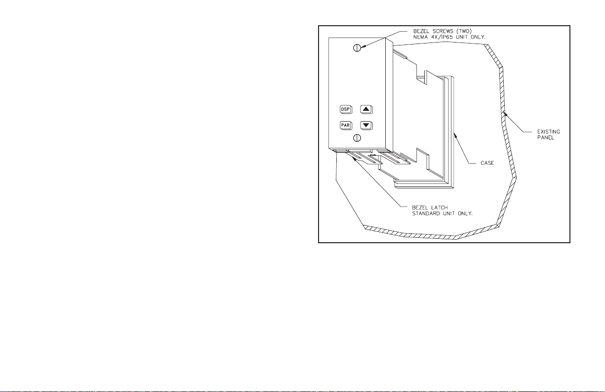
Prepare the panel cutout to the dimensions shown in Figure 1, Panel
Installation & Removal. Remove the panel latch and cardboard sleeve from
theunitand discard thecardboardsleeve. The unitshouldbe installed withthe
bezel assembly in place. Insert the unit into the panel cutout. While holding
the front of the unit in place, push the panel latch over the rear of the unit so
that the tabs of the panel latch engage in the slots on the case. The panel latch
should be engaged in the farthest forward slots possible. Tighten the screws
evenly until the unit is snug in the panel.
NEMA 4X/IP65 UNIT INSTALLATION
Theoptional NEMA4X/IP65 PCUController providesa watertightseal in
panelswith aminimum thicknessof 1/8inch. Theunits meet NEMA 4X/IP65
requirements for indoor use, when properly installed. The units are intended
to be mounted into an enclosed panel. Prepare the panel cutout to the
dimensionsshownin Figure 1,Panel Installation &Removal.Carefully apply
the adhesive side of the panel gasket to the panel cutout. Remove the panel
latch and cardboard sleeve from the unit. Discard the cardboard sleeve. The
unit should be installed with the bezel assembly inplace and the bezel screws
tightened slightly. Insert the unit into the panel cutout. While holding the
front of the unit in place, push the panel latch over the rear of the unit so that
the tabs of the panel latch engage in the slots on the case. The panel latch
should be engaged in the farthest forward slot possible. To achieve a proper
seal,tighten thelatch screwsevenly untilthe unitis snugin thepanel (Torque
to approximately 7 in-lbs [79 N-cm]). Do NOT over-tighten the screws.
Note: The installation location of the controller is important. Be sure to keep it
away from heat sources (ovens, furnaces, etc.), away from direct contact with
caustic vapors, oils, steam, or any other process by-products in which
exposure may affect proper operation.
Caution: Prior to applying power to the controller, the internal AC power
selector switch mustbe set. Damage tothe controller may occurif the switch is
set incorrectly.
-3-
Page 12

Figure 1, Panel Installation & Removal
-4-
Page 13
UNIT REMOVAL PROCEDURE
Toremove aNEMA 4X/IP65or standardunit fromthe panel,first unscrew
andremove the panel latch screws. Insert flat blade screwdriversbetween the
latch and the case on the top and bottom of the unit, so that the latches
disengage from the grooves in the case. Push the unit through the panel from
the rear.
REMOVING BEZEL ASSEMBLY
The bezel assembly, shown in Figure 2, must be removed from the case to
install or replace output modules, or to set the 115/230 VAC selector switch.
Disconnectpower to theunit and tothe output controlcircuits to eliminatethe
potential shock hazard when removing the bezel assembly. To remove a
standard bezel assembly (without bezel securing screws), press the latch
under the lower bezel lip and withdraw the bezel assembly. To remove the
sealedNEMA 4X/IP65 bezel assembly, loosen the twobezel securing screws
untila slight“click” is felt (the screws are retained in thebezel) andwithdraw
the assembly.
Caution: The bezel assembly contains electronic circuits that are damaged by
static electricity. Before removing the assembly, discharge stray static
electricity on yourbody by touching anearth ground point. It isalso important
that the bezel assembly be handled only by the bezel itself. Additionally, if it is
necessary to handle a circuit board, be certain that hands are free from dirt,
oil, etc., to avoid circuit contamination that may lead to malfunction. If it
becomes necessaryto ship the unit for repairs, placethe unit in its case before
shipping it.
Figure 2, Bezel Assembly
INSTALLING BEZEL ASSEMBLY
To install the standard bezel assembly, insert the assembly into the case
until the bezel latch snaps into position.
To install the NEMA 4X/IP65 bezel assembly,insert the assemblyinto the
case and tighten the bezel screws uniformly until the bezel contacts the case
and then turn each screw another half turn to insure a watertight seal (do not
over-tighten screws).
Caution: When substituting or replacing a bezel assembly, be certain that it is
done with the same model using the same Output Modules. Damage to the
controller may result if the unit’s output modules are not the same. A NEMA
4X/IP65 and a standard bezel assembly are NOT interchangeable.
OUTPUT MODULES
The main control, optional Alarm, optional Secondary output andoptional
Valve Position control output sockets must be fitted with the appropriate
output module. Output modules are shipped separately and must be installed
by the user.
Output Module Restrictions
Withsome models,the Alarm outputs and ValvePosition outputsshare the
same common terminal. When using these models, the same type of output
modules should be installed in these positions.
-5-
Page 14
Installing Output Modules
To install an output module into the controller, remove the bezel assembly
from the case (See Removing Bezel Assembly, page 5). Locate the correct
output module socket (OP1, AL1, or AL2/OP2, see Figure 6, Hardware, or
label outside of case) and plug the output module into the socket. No
re-programming is required. If changing an output module type, be sure the
appropriate output interface wiring changes are made. Re-install the bezel
assembly when complete.
Note: For Valve Positioner models, the circuit board markings have the
following meaning:
AL1 - Open Output
AL2/OP2 - Close Output
OP1 - Alarm #1 Output
OUTPUT MODULE “OUTPUT ON” STATE
Relay Normally open contact is closed
Logic/SSR Drive Source is active.
Triac Solid state switch is closed.
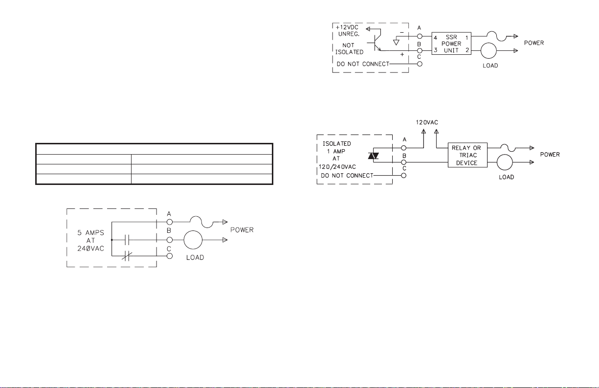
Typical Connections
Figure 3, Relay Module
Relay:
Type:Form-C(Form A withsomemodels. See OrderingInformation.)
Rating: 5 Amps @ 120/240 VAC or 28 VDC (resistive load), 1/8 HP @
120 VAC (inductive load).
Life Expectancy: 100,000 cycles at maximum load rating. (Decreasing
load and/or increasing cycle time, increases life expectancy).
Figure 4, Logic/SSR Drive Module
Logic/SSR Drive:
Type: Non-isolated switched DC, 12 VDC typical
Drive: 45 mA Max. Can drive multiple SSR Power Units.
Figure 5, Triac Module
Triac:
Type: Isolated, Zero Crossing Detection.
Rating:
Voltage: 120/240 VAC.
Max. Load Current: 1 amp @ 35°C
0.75 amp @ 50°C
Min. Load Current: 10 mA
Off State Leakage Current: 7 mA maximum @ 60 Hz
Operating Frequency: 20 to 400 Hz
Protection: Internal Transient Snubber, Fused.
SELECT AC POWER (115/230 VAC)
TheAC power to the unitmust be selectedfor either115 VAC or230 VAC.
The selector switch is located inside the case near the rear of the unit on the
main circuit board (see Figure 6, Hardware, or label on outside of case). The
unit is shipped from the factory with the switch in the 230 VAC position.
Caution: Damage to the controller may occur if the AC selector switch is set
incorrectly.
-6-
Page 15
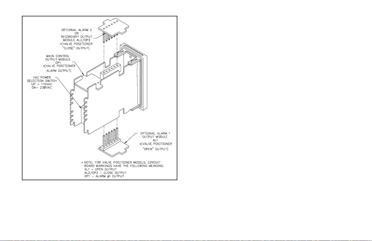
Figure 6, Hardware
EMC INSTALLATION GUIDELINES
Although this unit is designed with a high degree of immunity to
ElectroMagnetic Interference (EMI), proper installation and wiring methods
must be followed to ensure compatibility in each application. The type of
electrical noise, source or coupling method into the unit may be different for
various installations. In extremely high EMI environments, additional
measures may be needed. The unit becomes more immune to EMI with fewer
I/O connections. Cable length, routing and shield termination are very
importantand can mean the difference between a successful or a troublesome
installation. Listed below are some EMC guidelines for successful
installation in an industrial environment.
1. The unit should be mounted in a metal enclosure, which is properly
connected to protective earth.
2.Use shielded (screened) cables forall Signal andControl inputs.The shield
(screen) pigtail connection should be made as short as possible. The
connection point for the shield depends somewhat upon the application.
Listed below are the recommended methods of connecting the shield, in
order of their effectiveness.
a. Connect the shield only at the panel where the unit is mounted to earth
ground (protective earth).
b. Connect the shield to earth ground at both ends of the cable, usually
when the noise source frequency is above 1 MHz.
c. Connect the shield to common of the unit and leave the other end of the
shield unconnected and insulated from earth ground.
3.Never runSignal orControl cablesin the same conduit or raceway with AC
power lines, conductors feeding motors, solenoids, SCR controls, and
heaters, etc. The cables should be run in metal conduit that is properly
grounded. This is especially useful in applications where cable runs are
long and portable two-way radios are used in close proximity or if the
installation is near a commercial radio transmitter.
4.Signalor Control cableswithinan enclosure shouldberouted as farawayas
possible from contactors, control relays, transformers, and other noisy
components.
5. In extremely high EMI environments, the use of external EMI suppression
devices, such as ferrite suppression cores, is effective. Install them on
Signal and Control cables as close to the unit as possible. Loop the cable
through the core several times or use multiple cores on each cable for
additionalprotection. Install linefilters onthe power inputcable to theunit
-7-
Page 16
tosuppress power line interference. Installthem near thepower entrypoint
of the enclosure. The following EMI suppression devices (or equivalent)
are recommended:
Ferrite Suppression Cores for signal and control cables:
Fair-Rite # 0443167251 (RLC #FCOR0000)
TDK # ZCAT3035-1330A
Steward #28B2029-0A0
Line Filters for input power cables:
Schaffner # FN610-1/07 (RLC #LFIL0000)
Schaffner # FN670-1.8/07
Corcom #1VR3
Note: Reference manufacturer’s instructionswhen installinga line filter.
6. Long cable runs are more susceptible to EMI pickup than short cable runs.
Therefore, keep cable runs as short as possible.
7. Switching of inductive loads produces high EMI. Use of snubbers across
inductive loads suppresses EMI.
Snubbers:
RLC #SNUB0000
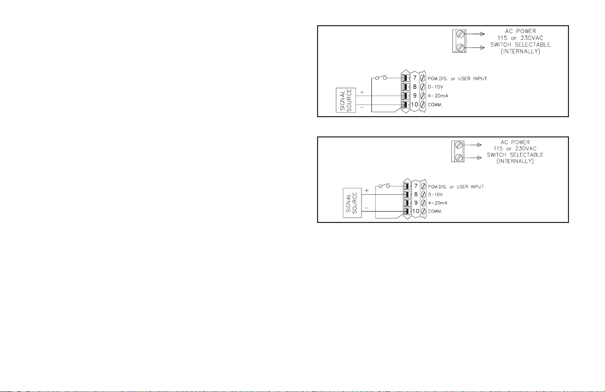
WIRING CONNECTIONS
After the unit has been mechanically mounted, it is ready to be wired. All
conductors should meet voltage and current ratings for each terminal. Also
cabling should conform to appropriate standards of good installation, local
codes and regulations. It is recommendedthat power supplied to the unit (AC
or DC) be protected by a fuse or circuit breaker.
Allwiring connectionsare madeon a fixed terminal block. When wiring the
unit, use the numbers on the label to identify the position number with the
proper function. Strip the wire, leaving approximately 1/4" (6 mm) bare wire
exposed (stranded wires should be tinned with solder). Insert the wire into the
terminal and tighten the screw until the wire is clamped tightly. Each terminal
canacceptup to two,18-gagewires. Wire eachterminalblock in thismanner.
Figure 7, 4-20 mA Connection
Figure 8, 0-10 V Connection
-8-
Page 17
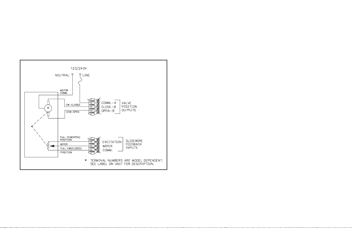
Valve Positioner Wiring
Units with Valve Positioner option have three output connections for
controlling the valve motor and three input connections for slidewire
feedback. The valve motor output connects to terminals labeled “Valve
Position Outputs”, terminals 1, 2 and 3. See Figure 9, Valve Positioner
Wiring for more details. Terminal 1 is the Valve motor supply common.
Terminal 2 is the Valve Close or CW output. Terminal 3 is the Valve Open or
CCW output. The valve motor must be fused with a suitable value.
Figure 9, Valve Positioner Wiring
Although RC snubbers are employed inside the controller to suppress
inductive“kicks” from the motor, itmay be necessaryto takefurther action to
reduce noise effects:
1) Use Triac Output Modules wherever possible. The Triac device
significantly reduces radiated EMI (Electromagnetic Interference).
The Triac Output Module also does not suffer from mechanical wear of
the contacts.
2) Use RC snubbers directly across the valve motor.
3) Use a separate AC supply for the valve motor.
Where possible, the valve motor control outputs and the slidewire
feedback input routing should be physically separated. Noise interference
from the outputs could couple into the slidewire feedback inputs, disrupting
proper operation.
The slidewire feedback inputs connect to the terminals labeled “Slidewire
Feedback Inputs”. The terminal placement varies with each model, see the
controller label for the actual terminals. For Velocity mode valve control the
slidewire feedback inputs are not necessary.
In some cases, it may be desirable to have an independent valve position
indicator. Red Lion Controls Model IMD1 can be wired in parallel with the
slidewire input’s Wiper and Comm. terminals for this purpose. The
approximate0to 0.9V signalcanbe scaled toindicatepercent valve position.
Linear DC Output Wiring
Units with Linear DC output option have two terminals to outputa4to20
mA or 0 to 10 VDCsignal. The type of LinearDC output is determined by the
model ordered. (See Ordering Information page 84, for available models.)
These terminals are labeled “4-20 mA (or 0-10 VDC) Analog Output Option,
Out+ and Out-”. The common of this output is isolated from main input
common , but is not isolated from the Second Analog Input Option common.
For proper operation always keep these commons isolated.
Second Analog Input Wiring
Unitswith SecondAnalog Input option have two input terminalsto receive
a4to 20 mAsignal.These terminals arelabeled“Second Input, 4-20mA+and
4-20 mA-”.Terminal placement varies with model. See unit label for actual
terminals.The commonof thisinput isisolated frommain inputcommon, but
is not isolated from the Linear DC Output common. For proper operation
always keep these commons isolated.
-9-
Page 18

Program Disable Or User Input Wiring
Some models have Terminal #7 as the User Input, which is programmable
for a variety of functions. Other models have Terminal #7 dedicated to the
program disable function. Any form of mechanical switch may be connected
to terminal #7. Sinking open collector logic with less than 0.7 V saturation
may also be used (no pull-up resistance is necessary).
Note: Do not tie the commons of multiple units to a single switch. Use either a
multiple pole switch for ganged operation or a single switch for each unit.
AC Power Wiring
PrimaryAC power is connected tothe separate twoposition terminalblock
labeled AC. To reduce the chance of noise spikes entering the AC line and
affecting the controller, an AC feed separate from that of the load should be
used to power the controller. Be certain that the AC power to the controller is
relatively “clean” and within the -15%, +10% variation limit. Connecting
powerfrom heavilyloaded circuits or circuits that also powerloads thatcycle
on and off, (contacts, relays, motors, etc.) should be avoided.
-10-
Page 19
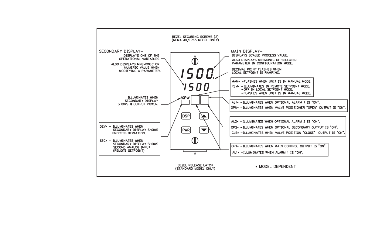
FRONT PANELDESCRIPTION
The front panel bezel material is
flame and scratch resistant, tinted
plastic. An optional NEMA
4X/IP65 bezel version is available
that meets NEMA 4X/IP65
requirements, when properly
installed. There are two 4-digit
LED displays, a red upper Main
Display and a lower green
Secondary Display.
There are up to six annunciators
depending on options installed,
with red backlighting, that
illuminate to inform the operator
of the controller and output status.
See Figure 10, Front Panel for a
description of the available
annunciators.
Four front panel buttons are
used to access different modes and
parameters. The following is a
description of each button.
BUTTON FUNCTIONS
DSP - In the normal operating
mode, the Display (DSP) button
is used to select one of the
operational parameters in the
secondary display. In the
Configuration Parameter
Modes, pressing this button
causes the unit to exit (escape) to the normal operating mode with no
changes made to the selected parameter.
UP, DN - In the normal operating mode, the Up/Down buttons can be used to
directly modify the setpoint value or % output power (manual mode only),
Figure 10, Front Panel
when viewed in the secondary display. Otherwise, the parameter must be
called to alter the value.
PAR - The Parameter (PAR) button is used to access, enter the change, and
scroll through the available parameters in any mode.
-11-
Page 20

OPERA TION OVERVIEW
CONTROLLER POWER-UP
Upon applying power, the controller delays control action and process
indication for five seconds to perform several self-diagnostic tests and
displaybasic controller information. Initially, the controller illuminatesboth
displays and all annunciators to verify that all display elements are
functioning. The controller then displays the programmed input type in the
main display. Concurrently, it displays the current revision number of the
operating system software in the bottom display. The controller checks for
correctinternal operationand displays an error message (E-XX) ifan internal
fault is detected (see Troubleshooting, page 73, for further information).
Upon completion of this sequence, the controller begins control action by
displaying the process value and updating the outputs based upon the PID
control calculation.
CONTROLLER POWER DOWN
At power down, the steady statecontrol value as well asall parameters and
control modes are saved, to provide a quick and predictable process response
on the next power-up.
When powering down the process, it is important to power down the
controller at the same time. This prevents the reset action of the controller
from shifting the proportional band while the process signal is dropping and
prevents excessive overshoot on the next process start-up.
PROCESS START-UP
After starting the process, the controller’s PID settings must be initially
“tuned” to the process for optimum control. Minimal tuning consists of
adjusting the Proportional Band, Integral Time, and Derivative Time
parameters to achieve the optimum response to a process disturbance. The
controller can be tuned once, but must be re-tuned if the process has been
changed significantly. Several options exist for tuning these parameters:
A)Usethe controller’s built-inAuto-Tunefeature (see Auto-Tune,page64).
B) Use a manual tuning technique (see Manual Tuning, page 76).
C) Use a third party tuning software package (generally expensive and not
always precise).
D) Use values based on control loop experience, calculated values or values
from a similar process.
If the controller is a replacement, the PID settings from the unit being
replaced may be used as good initial values. Be sure to consider any
differencesin theunits andthe PIDsettings whenreplacing. ThePID settings
maybe fine tunedby using thetechniques outlined inthe PID Controlsection.
Aftertuning the controller to theprocess, itis important to power theload and
the controller at the same time for best start-up response.
MANUAL (USER) & AUTOMATIC OPERATION
The controller can be transferred between Automatic control (closed
loop; PID or ON/OFF control) and Manual control (open loop). In the
Hidden Function Mode, the “trnf” parameter allows the operator to select
thedesired operatingmode. Toallow frontpanel switching between control
modes, program the transfer (trnf) parameter to “Enbl” in the Lockout
Module.The user input or RS485 serial interfaceoption may also be used to
perform the auto/manual transferfunction, independent of the setting in the
Lockout Module.
Manualoperation provides directcontrol of theoutput(s) from 0to +100%,
or -100% to +100% if the secondary output is installed. For Valve Positioner
models with slidewire feedback, this mode allows manual valve positioning.
TheMAN (REM forRemote Setpoint models)annunciator flashes toindicate
that the unit is in manual operation.
When transferring the controller mode from/to automatic, the control
power output(s) remain constant, exercising true “bumpless” transfer. When
transferringfrom manual to automatic, the power initially remains steadybut
integral action corrects (if necessary) the closed loop power demand at a rate
proportional to the Integral Time. The programmable high and low power
limit values are ignored when the unit is in manual operation.
-12-
Page 21

REMOTE AND LOCAL SETPOINT OPERATION
The controller setpoint mode can be switched between Local Setpoint
operation and Remote Setpoint operation. In the Hidden Function Mode, the
“SPSL”parameter allowsthe operator to select the desired setpointoperating
mode. To allow front panel switching between setpoint modes, program the
setpoint select parameter (SPSL) to “Enbl” in the Lockout Module. The user
input or RS485 serial interface option may also be used to perform the
setpointselectionfunction, independent ofthesetting in theLockoutModule.
Front panel annunciator REM is on for Remote setpoint operation and is off
for Local setpoint operation. When transferring the controller mode from/to
the setpoint modes, various controller response options are available (see
SPtr parameter, page 37).
-13-
Page 22
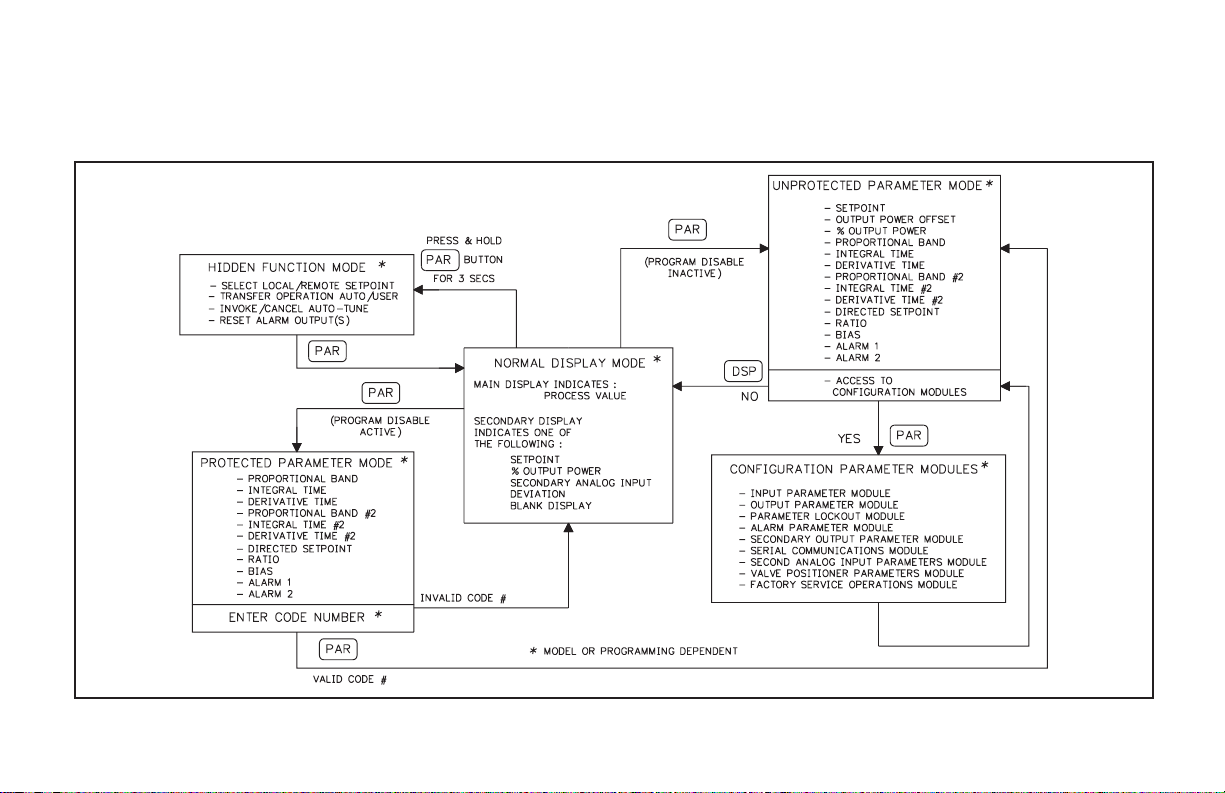
CONFIGURATION OF PARAMETERS
As supplied from the factory, the controller parameters have been
programmed to the values listed in the Programming Quick Reference
Tables.Theuser must modifythevalues, if necessary,tosuit the application.
Operation and configuration of the controller is divided into five distinct
operational/programming modes to simplify the operation of the controller:
Normal Display Mode, Unprotected Parameter Mode, Protected Parameter
Mode, Hidden Function Mode, and Configuration Parameter Modules. See
Figure 11, Operational/Programming Modes.
Figure 11, Operational/Programming Modes
-14-
Page 23

PARAMETER ENTRY
The PAR button is used to select the desired parameter. To modify the
parameter setting, use the UP and DOWN buttons. Press PAR to enter the new
value. The controller progresses to the next parameter. In a Configuration
Parameter Module, pressing the DSP button causes the new value to be
rejected, the controller displays “End”, and returns to the Normal Display
Mode.For those parameters outside the Configuration Parameter Modules, the
new value takes effect and is committed into controller memory WHILE the
value is keyed in. The following is a list of commonly modified parameters:
Setpoint
Output Power
Output Power Offset
Proportional Band
Integral Time
Derivative Time
Proportional Band #2
Integral Time #2
Derivative Time #2
Directed Setpoint (Cascade)
Ratio
Bias
Alarm 1 Value
Alarm 2 Value
Note: While in a Configuration Parameter Module, all new parameters are
rejected and the old ones recalled if power is removed from the controller. If
power is removed while modifying any parameter, be certain to check the
parameter for the proper value.
NORMAL DISPLAY MODE
In the normal display mode, the process value is always displayed in the
main display. By successively pressing the DSP button, one of these
operational parameters can be viewed in the secondary display (model
dependent):
Setpoint
% Output Power
Second Analog Input (Remote Setpoint)
Process Setpoint Deviation
Each of these displays can be independently locked out from appearing or
from being modified by the user (see Lockouts Module,page 27). Only from
the normal display mode can access be gained to the other modes
(Unprotected, Protected, or Hidden).
MODIFYING A SECONDARY DISPLAY PARAMETER FROM
THE FRONT PANEL
Thecontroller must be in thenormal displaymode to modify the secondary
displayparameters. The Setpointvalueand % outputpower (in manualmode)
are the two parameters which may be modified. The other parameters are
read-out values only.
Setpoint Value - Use the up and down arrow buttons to modify the setpoint
value when viewed, if not locked. If locked, the setpoint can be changed in
the unprotected mode when “SP” is viewed, independent of viewing in the
secondary display. The setpoint value is confined to the programmable
setpoint limit values (SPLO & SPHI, Input Module 1).
%Output Power -The %Output Power canonly bechanged when theunit is
in the manual mode. See Manual (User) and Automatic Operations, page
12. The annunciator % PW lights, and the Manual annunciator flashes
when viewed. Use the up and down arrow buttons to modify the % Output
Power if not locked. If locked, the % output power can be changed in the
unprotected mode when “OP” is viewed, independent of viewing in the
secondarydisplay. The %output power isnot confined totheprogrammable
output power limit values (OPLO & OPHI, Output Module 2).
-15-
Page 24

UNPROTECTED PARAMETERMODE
The Unprotected Parameter Mode is accessed by pressing the PAR button
from the normal display mode with program disable inactive. In this mode,
the operator has access to the list of the most commonly modified controller
parameters. At the end of the list, a configuration “access point” allows the
operator to enter the configuration parameter modules. These modules allow
access to the fundamental set-up parameters of the controller. When the
program list has been scrolled through, the controller displays “End” and
returns to the normal display mode. The unit automatically returns to the
normal display mode if no action is taken.
UNPROTECTED PARAMETER MODE REFERENCE TABLE
Display Parameter
SP Setpoint Confined to
OPOF %Output
Power Offset
OP Output
Power
Prop Proportional
Band
Intt Integral
Time
dErt Derivative
Time
Pb-2 Proportional
Band #2
(Secondary)
It-2 Integral
Time #2
(Secondary)
Range and
Units (Factory
Setting Value)
range of limits
SPLO, SPHI,
(0)
-99.9% to
100.0%
(0.0)
-99.9% to
100.0%
(0.0)
0.0 to 999.9% of
scaled input
range
(4.0)
0 to 9999 sec.
(120)
0 to 9999 sec.
(30)
0.0 to 999.9% of
Scaled input
range
(4.0)
0 to 9999 sec
(0)
Appears only if setpoint value is
locked (LOC) or read only (rEd).
Appears only if integral time (Intt)
= 0 and controller is in automatic
mode.
Appears only if controller is in
user (manual) mode and % output
power is locked (LOC) or read
only (rEd). This parameter is not
limited to output power limits
(OPLO & OPHI).
0.0% is ON/OFF control. If using
ON/OFF mode, set control
hysteresis appropriately.
0 is off. This parameter does not
appear if proportional band =
0.0%.
0 is off. This parameter does not
appear if proportional band =
0.0%.
0.0% is ON/OFF control. Second
Analog Input models only.
0 is off. This parameter does not
appear if proportional band #2 =
0.0%. Second Analog Input
models only.
Description/
Comments
-16-
Page 25

Display Parameter
dt-2 Derivative
Time #2
(Secondary)
SP-2 Internal
Cascade
Directed
Setpoint
rtio Remote
Setpoint ratio
multiplier
bIAS Remote
Setpoint bias
offset
AL-1 Alarm 1
Value
AL-2 Alarm 2
Value
CNFP Configuration
Access Point
End Unit returns
to Normal
Display Mode
Range and
Units (Factory
Setting Value)
0 to 9999 sec
(0)
-999 to 9999
(N/A)
0.001 to 9.999
(1.000)
-999 to 9999
(0)
-999 to 9999
(0)
-999 to 9999
(0)
____ Brief display message.
0 is off. This parameter does not
appear if proportional band #2 = 0.0%.
Second Analog Input models only.
Second Analog Input models only.
Read only parameter.
Second Analog Input models.
Second Analog Input models.
Alarm option models only.
This parameter does not appear if the
alarm option is not specified, the
secondary output option is installed,
or if locked (LOC).
NO
Return to normal display mode.
Enter Configuration modules.
1-IN
Configure input parameters.
2-OP
Configure output parameters.
3-LC
Configure parameter lockouts.
4-AL
Configure alarm parameters (opt.)
5-02
Configure secondary output (opt.)
6-SC
Configure serial communication
parameters (optional).
Configure second analog input
7-2N
parameters (optional)
Configure valve positioner
8-VP
parameters (optional)
Factory service operations (Qualified
9-FS
technicians only)
Description/
Comments
-17-
Page 26

PROTECTED PARAMETERMODE
The Protected Parameter Mode is accessed from the normal display mode
by pressing the PAR button with program disable active. In this mode, the
operator has access to the list of the most commonly modified controller
parameters that have been “unlocked” in the configuration parameter
lockouts module. Depending on the code number entered in the lockout
PROTECTED PARAMETER MODE REFERENCE TABLE
Display Parameter
Prop Proportional
Band
Intt Integral
Time
dErt Derivative
Time
Pb-2 Proportional
Band #2
(Secondary)
It-2 Integral
Time #2
(Secondary)
dt-2 Derivative
Time #2
(Secondary)
SP-2 Internal
Cascade
Directed
Setpoint
Range and
units (Factory
Setting Value)
0.0 to 999.9%
of scaled input
range
(4.0)
0 to 9999 sec.
(120)
0 to 9999 sec.
(30)
0.0 to 999.9%
of scaled input
range
(4.0)
0 to 9999 sec.
(0)
0 to 9999 sec.
(0)
-999 to 9999
(N/A)
Description/Comments
0.0% is ON/OFF control. If using
ON/OFF mode, set control
hysteresis appropriately. This
parameter does not appear if
locked (LOC).
0 is off. This parameter does not
appear if proportional band = 0.0%
or locked (LOC).
0 is off. This parameter does not
appear if proportional band = 0.0%
or locked (LOC).
0.0% is ON/OFF control. Second
Analog Input models only.
0 is off. This parameter does not
appear if proportional band #2=
0.0%, or if locked (LOC). Second
Analog Input models only.
0 is off. This parameter does not
appear if proportional band #2=
0.0%, or if locked (LOC). Second
Analog Input models only.
Second Analog Input models only.
Read only parameter.
module, access to the unprotected parameter mode and hence, the
configuration parameter modules is possible. The controller returns to the
normal display mode if the unprotected mode and configuration modules
cannotbeaccessed. This modecannot be accessedifall parameters arelocked
out in Configuration Module 3.
Display Parameter
rtio Remote
setpoint
ratio
multiplier
bIAS Remote
setpoint
bias offset
AL-1 Alarm 1
value
AL-2 Alarm 2
value
Code Access
code to
unprotected
mode
End Unit returns
to normal
display
mode.
Range and
units (Factory
Setting Value)
0.001 to 9.999
(1.000)
-999 to 9999
(0)
-999 to 9999
(0)
-999 to 9999
(0)
0to250
(0)
Description/Comments
Second Analog Input models
only.
Second Analog Input models
only.
Alarm option models only.
This parameter does not appear
if the alarm option is not
specified, the secondary output
option is installed, or if locked
(LOC).
To gain access to unprotected
mode, enter the same value for
Code as entered in parameter
lockouts. This parameter does
not appear if zero is entered in
code parameter lockout.
Brief display message display
mode.
-18-
Page 27

FRONT PANELPROGRAM DISABLE
There are several ways to limit the programming of parameters from the
frontpanel buttons. Thesettings of theparametersin the LockoutModule, the
code number entered, and the state and/or function programmed for the User
Input (Terminal #7) affect front panel access.
It is possible to have the program disable function on versions with the
User Input, even if the User Input is not programmed for program disable
(PLOC),by the useofa code number.Versions that donothave the UserInput
are dedicated to the program disable function.
The following charts describe the possible program disable settings
depending on your model.
MODELS WITH USER INPUT
User Input State Code Number Description
Inactive or User
Input not
programmed for
PLOC
Active with User
Input programmed
for PLOC
Active with User
Input programmed
for PLOC
OR
User Input not
programmed for
PLOC
Note: A universal code number 222 can be entered to gain access to the
unprotected mode and configuration modules, independent of the
programmed code number.
0 Full access to all modes and
0 Access to protected parameter
Any # between
1 & 250
parameter modules.
mode only. Code number does not
appear.
Access to protected parameter
mode. Correct programmed code
number allows access to
unprotected parameter mode and
configuration modules.
MODELS WITH PROGRAM DISABLE
Program Disable Code Number Description
Inactive 0 Full access to all modes and
Active 0 Access to protected parameter
Active Any # between
1 & 250
Note: A universal code number 222 can be entered to gain access to the
unprotected mode and configuration modules, independent of the
programmed code number.
parameter modules.
mode only. Code number does not
appear.
Access to protected parameter
mode. Correct programmed code
number allows access to
unprotected parameter mode and
configuration modules.
-19-
Page 28

HIDDEN FUNCTION MODE
The Hidden Function Mode is only accessible from the normal display
mode by pressing and holding the PAR button for three seconds. These
functions must be unlocked in ConfigurationModule #3. Factory settings are
locked. In this mode, these controller functions can be performed.
Local/Remote Setpoint Selection
Automatic/Manual Transfer
Initiate/Cancel Auto-tune
Reset Alarm Events
Each function may be “locked out” in the Configuration parameter
lockoutsmodule. The PAR button is used toscroll to the desired function and
the up and down buttons are used to select the operation. Pressing the PAR
button while the function is displayed executes the function, and returns the
unitto the normaldisplay mode.Pressing the DSPbutton exitsthis mode with
no action taken. The unit automatically returns to the normal display mode if
no action is taken.
HIDDEN FUNCTION MODE REFERENCE TABLE
Display Parameter
SPSL Select
Local or
Remote
Setpoint
trnF Transfer
mode of
operation
tUNE Auto-tune
invocation
ALrS Alarm reset UP key resets Alarm 1
Range and Units
(Factory Setting Value)
LOC - Local Setpoint
rE_t - Remote Setpoint
(LOC)
Auto - Automatic control
User - Manual control
(Auto)
Yes: starts the
auto-tune sequence.
No: terminates the
auto-tune sequence.
Prl - tune primary
(Cascade)
SEC - tune secondary
(Cascade)
(NO)
DOWN key resets
Alarm 2
Description/Comments
Appears only for models
with Second Analog
Input. “SPtr” determines
nature of controller
response.
This step does not
appear if locked (LOC).
Exits to normal display
mode if executed.
This step does not
appear if locked (LOC) or
exits to normal display
mode if executed. These
parameters appear only if
Second Analog Input
Internal Cascade is
selected.
This step does not
appear if alarm option not
installed, if locked (LOC)
or previous step
performed.
-20-
Page 29

CONFIGURA TION PARAMETER MODULES
Accessible from the unprotected parameter mode, the configuration
parameter modules allow the operator access to the controller’s fundamental
set-up parameters. There are nine possible configuration stages that can be
accessed. At the configuration stage access point “CNFP”, the operator uses
the UP & DOWNarrow buttons to select the desired configuration parameter
module. Press the PAR button to enter the module where the settings can be
viewed or modified. The PAR button is used to scroll through the parameters
and the UP and DOWN buttons are used to modify the parameter value. The
PAR button enters the desired choice, advancing to the next parameter. The
operator can press the DSP button to exit (escape) without modifying the
parameter. The unit returns to the normal display mode. After the parameters
in a module are viewed or modified, the unit returns to the configuration
access point, allowing access to other modules.
INPUT MODULE (1- IN)
The controller has several input set-up parameters that must be
programmed prior to setting any other controller parameters.
Input Type (tYPE)
Select the signal input type Voltage (VOLt), or Current (Curr). The
appropriate signal input terminal for voltage is #8 and for current is #9.
Square Root Linearization (root) (Optional)
The main input can be linearized by use of the square root function. See
Square Root Linearization, page 35, for a complete description of the square
root function.
The“root” parameter inProgram Module1 applies tothe maininput, and the
“root” parameter in Program Module 7 applies to the Second Analog Input.
Decimal Point Position (dCPt)
Select the desired decimal point position for the scaled display. The
selected decimal point position appears in the following parameters; rnd,
dSP1, dSP2, SPLO, SPHI, SP, AL1, AL2, db-2, AHYS, and CHYS.
0
0.0
0.00
0.000
Rounding Increment ( rnd)
Rounding values other than “1” causes the scaled number to ‘round’ to the
nearest rounding increment selected (ie. rounding of‘5’ cause ‘122’to round
to ‘120’ and ‘123’ to round to ‘125’). If the process is inherently jittery, the
display value may be rounded to a higher value than “1”. If the range of the
process exceeds the required resolution, (ex. 0-1000 PSI, but only 10 PSI
resolution required), a rounding increment of 10 will effectively make the
display more stable.
This programming step is usually used in conjunction with programmable
digital filtering to help stabilize display readings (If display stability appears
to be a problem and the sacrifice in display resolution is unacceptable,
program higher levels of digital filtering or increase the level of process
dampening). Rounding increments of 10, 20, 50, and 100 may also be used to
add “dummy zeroes” to the scaled readings, as desired.
1
2
5
10
20
50
100
The rounding increment is for the controller’s display only and does not
affect (degrade) the control accuracy of the unit.
-21-
Page 30

Input Signal Filter and Display Update Rate (FLtr)
Selectthe relativedegree of inputsignal filteringand display update rate.
The filter is an adaptive digital filter that discriminates between
measurement noise and actualprocess changes. Therefore, the influence on
step response time is minimal. If the signal is varying too greatly due to
measurement noise, increase the filter value. Additionally, with large
derivative times, control action may be too unstable for accurate control.
Increase the filter value. Conversely, if the fastest controller response is
desired, decrease the filter value.
The Auto-tune procedure sets the filter value appropriate to the process
characteristics. Also see Output Power Dampening parameter (OPdP), page
25, for filtering the output.
Fltr-0to4
0 = least input filtering
3 = most input filtering
4 = most input filtering and slower (2/sec) display update rate
(outputs update at 10/sec rate)
Scaling Points
Prior to installing and operating the controller, it may be necessary to
change the scaling to suit the display units particular to the application.
Although the unit has been programmed at the factory, the scaling will
generally have to be changed.
The controller is unique in that two different scaling methods are available.
The operator may choose the method that yields the easier or more accurate
calibration. The two scaling procedures
are similar in that the operator keys in the
display values and either keys in or
applies a signal value that corresponds to
those scaling points. The location of the
scaling points should be near the process
endlimits,for the bestpossibleaccuracy.
Once these values are programmed
(coordinates on a graph), the indicator
calculates the slope and intercept of the
signal/display graph automatically. No
span/zero interaction occurs, making
scaling a one-pass exercise.
Figure 12, Scaling Points
Before programming the indicator, it is advised to organize all the data for
the programming steps to avoid possible confusion.
To scale the indicator, two signal values and two display values that
correspond to the signal values must be known. These four values are used to
complete the scaling operation. An example is listed below:
Scaling Point #1 Scaling Point #2
0.0% @ 4.00 mA & 100.0% @ 20.00 mA
Reverse acting indication can be accomplished by either reversing the two
signal points or the display value points, but not both. If both are reversed,
then forward (normal) acting indication will occur. In either case, do not
reverse the input wires to correct the action.
Display Values (dSP1 & dSP2)
Key-in the display value for scaling point one and scaling point two.
dSP1 -999 to 9999 (Ex. 0.0%)
dSP2 -999 to 9999 (Ex. 100.0%)
Signal Input Values (INP1 & INP2)
The signal input value can either be keyed in via the front panel buttons or
aninput signal can be applied to the appropriate signalinput terminals.When
entering the signal input parameter, the unit is in the key-in mode.
Key-in Method
Key-in the signal value for scaling point one and scaling point two.
INP1 -999 to 9999 (Ex. 0.00 VDC or 4.00 mA DC)
INP2 -999 to 9999 (Ex. 10.00 VDC or 20.00 mA DC)
Signal Input Method
To change to the apply signal method press the DSP button. Front panel
annunciators % PW and DEV will flash, and the display indicates the signal
value applied to the input terminals. The unit can be toggled to the key-in
method by pressing the DSP button again.
Signal Range Display Range
4.00 to 20.0 mA DC 0.00 to 20.00
0.00 to 10.00 VDC 0.00 to 10.00
Whenthe desiredvalue isindicated onthe display, press the PAR button to
store the value and advance to the next parameter.
-22-
Page 31

Setpoint Limit Values (SPLO & SPHI)
The controller has programmable high and low setpoint limit values to
restrict the setting range of the setpoint. Set the limit values so that the
setpoint value cannot beset outside the safe operating area of the process. On
models equipped with Second Analog Input, configured as a Remote
Setpoint, the Remote Setpoint reading is also restricted to these limits.
SPLO - -999 to 9999
SPHI - -999 to 9999
Setpoint Ramp Rate (SPrP)
The setpoint can be programmed to ramp independent of the controller’s
decimal point position and rounding increment. The setpoint ramp rate can
reduce sudden shock to the process, reduce overshoot on start-up or setpoint
changes, or ramp the process at a controlled rate.
SPrP - 0.1 to 999.9 units/minute
Aramp value ofzero disablessetpoint ramping. Ifthe optional userinput is
programmed for setpoint ramp, it affects the enabling and disabling of
setpoint ramping (See User Input, page 23). Setpoint ramping is initiated on
power-up or when the setpoint value is changed and is indicated by a decimal
point flashing in the far right corner of the main display.
Figure 13, Setpoint Ramp Rate
Once the ramping setpoint reaches the target setpoint, the setpoint ramp
rate disengages until the setpoint is changed again. If the ramp value is
changed during ramping, the new ramp rate takes effect. If the setpoint is
ramping prior to invoking Auto-Tune, the ramping is suspended during
Auto-Tune and then resumed afterward using the current display as a starting
value. Deviation and band alarms are relative to the target setpoint, not the
ramping setpoint. If the analog output isprogrammed to transmitthe setpoint
value, the instantaneous ramping setpoint value is transmitted.
Note: Depending on the ramp rate relative to the process dynamics, the actual
scaled process value may not track the ramping setpoint value.
On models equipped with Second Analog Input, configured as Remote
Setpoint, this parameter may be used to establish a maximum rate of change
of the Remote Setpoint reading. If the controller or transmitter that supplies
the Remote Setpoint reading is swinging too wildly, or changing too fast,
resulting in control problems, the ramp rate can be used to reduce the rate of
change of the Remote Setpoint reading. When ramping in Remote Setpoint
operation, the flashing decimal point is suppressed. The units of ramping for
Remote Setpoint operation are 0.1 to 999.9 LSD/minute.
User Input (InPt)
The user input may be programmed to perform a variety of controller
functions. The input must be in its active state for 100 msec minimum to
perform the function. The unit executes all functions in 100 msec, except the
printrequest function thatrequires 110 to200 msec fora response. Afunction
is performed when the User Input, (Terminal 7) is used in conjunction with
common (Terminal 10).
Note: Do not tie the commons of multiple units to a single switch. Use either a
multiple pole switch for ganged operation or a single switch for each unit.
Below is a list of the available functions.
PLOC - Program Lock. A low level enables the program disable function
which places the unit in the Protected Parameter Mode.
Note: Front panel disable is possible without using this program lock
function, see Front Panel Program Disable, page 19.
ILOC - Integral Action Lock. A low level disables the integral action of the
PID computation. A high level resumes the integral action.
trnF - Auto/Manual Transfer. A negative transition places the unit in the
manual (user) mode and a positive transition places the unit in the
automatic operating mode. The output is “bumpless” when transferring to
either operating mode.
-23-
Page 32

User Input (InPt) (Cont’d)
SPrP - Setpoint Ramp. A low level terminates setpoint ramping and the
controller operates at the target setpoint. Terminating setpoint ramping is
the same as setting the ramp rate to zero (SPrP = 0.0). A high level enables
the programmed setpoint ramp rate.
ALrS - Alarm Reset. If the alarm option is installed, a low level resets the
alarm(s) to their inactive state as long as the user input is low.
Prnt - Print Request. A low level transmits the print options selected in the
serial communications module (6-SC). If the user input is held low, after
the printing is complete a second print request is issued.
SPSL - Select Local or Remote Setpoint. On models equipped with Second
Analog Input, configured as Remote Setpoint, a negative transition
engagesRemoteSetpoint operation anda positive transitionengagesLocal
Setpoint operation. Select the controller output response to the
Local/Remote transfer operation (bumpless, tracking, etc) by the setpoint
transfer parameter (SPtr).
OUTPUT MODULE (2-OP)
The controller has parameters that affect how the main control output
(OP1) responds to process changes and signal overdrive actions.
Time Proportioning Cycle Time (CYCt)
Theselection ofcycle timedepends onthe timeconstant ofthe processand
the type of output module used.
CYCt - 0 to 250 seconds
For best control, a cycle time equal to 1/10 of the process time constant, or
less is recommended; longer cycle times could degrade process control, and
shortercycle times providelittlebenefit at theexpense of shortenedrelay life.
Whenusing a Triac module ora Logic/SSRdrive output module with theSSR
Power Unit, a relatively short cycle time may be selected.
A setting of zero keeps the main control output and front panel indicator off.
Therefore, if using the analog output for control, the main output and indicator
can be disabled. This parameter is skipped for Valve Positioner models.
Output Control Action (OPAC)
Themain controloutput (OP1) channel is programmable for reverseacting
or direct acting. Most control applications use reverse acting (See ON/OFF
Control, page 62).
OPAC - rEv (Reverse acting)
drct (Direct acting)
Ifdrct (directacting) isselected, themain output (OP1) is direct acting and
the secondary output (OP2) is reverse acting. The secondary output always
maintains the opposite setting of the main output.
Note: Whenusing a relayoutput module, thecontrol action may also be reversed
by using the normally closed contacts.
The linear DC analog output, when assigned to output power (OP) for
control purposes, tracks the controller output power demand. A direct acting
linear output signal can be implemented in two ways:
1. Use “direct” for output control action (OPAC).
2. Interchange the two analog output scaling points ANLO & ANHI (See
Linear DC Analog Output,page 26).
-24-
Page 33

Output Power Limits (OPLO & OPHI)
Enter the safe output power limits for the process. These parameters may
also be used to limit the minimum and maximum controller power due to
process disturbances or setpoint changes, to reduce overshoots by limiting
the process approach level.
OPLO & OPHI - 0 to 100%
If the secondary output option is installed, the limits range from:
OPLO & OPHI - -100 to 100%
With the secondary output option installed, the Lower Limit can be set to
less than 0% to limit maximum secondary output power or set to greater than
0% to limit minimum main control output power. Set the High Limit to less
than0% tolimit minimum secondary output power or greater than 0%to limit
maximum main control outputpower. When controlling power in the manual
mode, the output power limits do not take effect.
Input Overdrive Preset Power (OPFL)
If an input overdrive signal is detected, the control output(s) default to a
preset power output.
OPFL - 0% (OP1 output full “off”) to 100% (OP1 output full “on”)
If the secondary output option is installed, the range is extended from:
OPFL - -100% to +100%
At0% bothoutputs are off, at 100% OP1 is on and OP2 is off, and at -100%
OP2 is on and OP1 is off. The alarm outputs always have an up-scale drive
(+9999), independent of this setting, for an input overdrive signal.
For position mode valve controllers, the valve is positioned according to
the setting of this parameter.
For velocity mode valve controllers, the following actions occur:
Velocity mode: OPFL = 0%, valve CLOSE output activates
OPFL = 100%, valve OPEN output activates
OPFL = any other setting, both valve outputs disable
Output Power Dampening (OPdP)
The output power calculated by the PID controller can be dampened
(filtered) to reduce the controller output activity. Those processes with high
gain and/or derivative times or those processes with a relatively high noise
content can benefit from the dampening action.
OPdP-0to250seconds
The dampening parameter is expressed as a time constant in seconds.
Increasing the value increases the dampening or filtering effect. A value of
zero disables output power dampening. The amount of dampening to be used
dependsprimarily on the response time of the process andthe amount of final
actuator activity desired. Generally, dampening times in the range of 1/20 to
1/50 of the controller’s integral time (or process time constant) prove to be
effective.Dampeningtimes longer thanthese may causecontrollerinstability
due to the added lag effect of too much filtering.
In the case where a relatively high dampening time is desired, the
controller’s proportional band may be increased to restore an adequate
stability margin. The Auto-tune procedure of the controller sets the
dampening value appropriate to the characteristics of the process.
ON/OFF Control Hysteresis Band (CHYS)
The controller can be placed in the ON/OFF control mode by setting the
proportionalband to 0.0%. The control hysteresis valueaffects only the main
control output (OP1).
CHYS - 1 to 250 units
The hysteresis band should be set to a minimum value to eliminate output
chatter at the setpoint. Set the hysteresis band to a sufficient level prior to
invoking Auto-Tune. Internal cascade controllers, secondary loop, have a
fixed hysteresis of 1.5% of scaled range.
-25-
Page 34

Auto-Tune Dampening Code (tcod)
Prior to invoking Auto-Tune, the dampening code should be set to achieve
the desired dampening level under PID control. After Auto-tune is complete,
changes to “tcod” parameter have no effect until Auto-tune is re-started.
When set to 0, this yields the fastest process response with possible
overshoot. A setting of 4 yields the slowest response with the least amount of
overshoot.Dampeningcodes of 0or1 are recommendedformost processes.
Figure 14, Dampening Code
Linear DC Analog Output (ANAS, ANLO, ANHI, ANdb, ANUt)
(Optional)
The Linear DC output can be programmedto transmit oneof the following
controller parameters:
ASSIGN DC OUTPUT (ANAS):
OP – Percent output power
INP – Scaled input process value
dEV – Process setpoint deviation
SP – Process setpoint value
dE-2 – Process deviation of secondary loop (Internal Cascade only)
SP-2 – Process setpoint of secondary loop (Internal Cascade only)
Withhigh and low digital scaling points, the range ofthe Linear DC output
can be set independent of the controller’s range. This allows interfacing
directly with chart recorders, remote indicators, slave controllers, or linear
power control units.
ANLO (4 mA or 0 VDC) – -999 to 9999
ANHI (20 mA or 10 VDC) – -999 to 9999
Linear DC output deadband (ANdb) and linear DC output update time
(ANUt) parameters are additional parameters used for control purposes
(ANAS=OP). The deadband parameter requires that the output power, in
percent, must change more than the deadband amount in order for the output
to update. A value of 0.0 disables the deadband action. The linear output
update time updates the output at the time interval specified. A value of 0
secondsupdatesthe output atthecontroller’s scan rate(10/sec).In the manual
mode of operation both parameters are overridden. The front panel indicator
OP1 and main output can be disabled by setting the time proportioning cycle
time equal to zero (CYCt = 0).
Note: Valve Position controllers disable the “OPEN” and “CLOSE” outputs
when the linear DC output is assigned to output power. In this case, the
slidewire feedback signal may be used to verify valve position.
ANdb – 0.0 to 25.0%
ANUt – 0 to 250 seconds
For setpoint transmission, (external cascade control used with another
controller),the controller transmits the instantaneous ramping setpoint,not
the target value, when the controller is ramping the setpoint. For models
with Remote Setpoint, the linear output transmits the active setpoint (local
or remote).
-26-
Page 35

Example: Chart Record Process Display Value (0 to 10 VDC):
The process range is 300-700. Programming 300 for ANLO (0 VDC
value) and 700 for ANHI (10 VDC value) yields full scale deflection for a
chart recorder (0 to 10 VDC). The 0 to 10 VDC output is assigned to
transmit the input reading (ANAS = INP).
Example: Linear Control Output (4 to 20 mA):
A linear DC input power control unit is used for process control. An
outputcontrol deadbandof ±2.0% andan output update time of10 seconds
is desired. The following set-up values illustrate the configuration:
ANAS = OP
ANLO = 0.0%
ANHI = 100.0%
ANdb = 2.0%
ANUt = 10 seconds
Figure 15, Linear DC Output
LOCKOUTS MODULE (3-LC)
The controller can be programmed to limit operator access to various
parameters, control modes, and display contents. The configuration of the
lockouts is grouped into three sections: Lower Display Lockouts, Protected
Mode Lockouts and Hidden Mode Lockouts.
Lower Display Lockouts (SP, OP, IN-2, dEv, bdSP)
Thecontents of thesecondary display canbe changed inthe normal display
mode by successively pressing the DSP button. This action scrolls through
the possible display parameters, when enabled.
The parameters can be set for one of the following:
LOC (Lockout) – Prevents the parameter from appearing in the
secondary display.
rEd (Read only) – Parameter appears, but cannot be modified.
Ent (Entry) – Parameter appears and can be modified.
The lower display content possibilities are:
SP – Setpoint Value
OP* – % Output Power
IN-2* – Second analog input (Remote setpoint)
dEv* – Setpoint Deviation
bdSP – Blank Display
If all parameters are set to lock “LOC”, the display remains on the last
parameter that was viewed.
*Note: These parameters are model specific and may not appear in the
programming sequence.
Note: If a parameter is active in the lower display and is then subsequently locked
out, press “DSP”once in the normal displaymodeto remove it fromthedisplay.
-27-
Page 36

Protected Mode Lockouts (Code, PID, PID2, rtbS & AL)
The protected mode is active when program disable is active. The
parametersinthe protected modecanbe set foroneof the followingmodes:
LOC (Lockout) – Prevents the parameter from appearing in the
rEd (Read only) – Parameter appears, but cannot be modified.
Ent (Entry) – Parameter appears and can be modified.
protected mode.
The code number allows access to the unprotected mode. To enter the
unprotected mode from the protected mode, the code number entered must
matchthe code number entered here.See Front Panel ProgramDisable,page
19, for a description of the various program access levels.
Code – 0 to 250
PID – Permits access to the main PID parameters
PID2
S – Permits access to the secondary PID parameters
rtbS
S – Permits access to Remote Setpoint ratio and bias
AL
S – Permits access to the alarm value(s).
parameters
Hidden Mode Lockouts (ALrS, trnF, tUNE and SPSL)
The hidden mode is accessible from the normal display mode by pressing
andholdingthe PAR buttonforthree seconds. Theparameterscan be setfor:
LOC (Lockout) – Prevents the parameter from appearing in the
ENbL (Enable) – Allows operator to perform the selected hidden
hidden mode.
mode function.
The functions available in the hidden mode are accessible independent of
the status of program disable.
ALrSS – Reset (override) the alarm output(s).
SPSL
S – Select Local or Remote Setpoint operation.
trnf – Select Automatic or Manual operation.
tUNE – Invoke or cancel Auto-Tune.
S Note: These parameters are model specific and may not appear in the
programming sequence.
ALARM MODULE (4-AL) (OPTIONAL)
The controller may be optionally fitted with the dual alarm option (AL1
and AL2). Some models are equipped only with a single alarm (AL1). One of
three types of output modules (Relay, Logic/SSR Drive or Triac) must be
ordered separately and installed into the appropriate alarm channel socket.
The output modules may be replaced or interchanged (with appropriate
wiring considerations) at any time without re-programming the controller.
The alarm values can be accessed in configuration module (4-AL), the
unprotected mode, and in the protected mode, if not locked.
Afront panel annunciatorilluminates toindicate that thealarm output ison
(AL1 for alarm 1 and AL2 for alarm 2).
Note: When deviation low-acting with positive alarm value (d-LO), deviation
high-acting with negative value (d-HI), or Band inside-acting (b-IN) is
selected for the alarm action, theindicator is “OFF”when the alarmoutput is
“ON”. These alarm modes latch the outputs when the output is “ON”, when
selected for latched operation.
Caution: In applications where equipment or material damage, or risk to
personnel, due to controller malfunction could occur, an independent and
redundant process limit indicator with alarm outputs is strongly
recommended. Red Lion Controlsoffers various units (such as an IMP, IMD1
or IMD2) that may be used for this purpose. The indicators should have input
and AC power feeds independent from the other equipment.
Alarm Action (Act1, Act2)
The alarm(s) may be independently configured for one of the following
modes:
Absolute High Acting (A-Hi)
Absolute Low Acting (A-LO)
Deviation High Acting (d-Hi)
Deviation Low Acting (d-LO)
Band Inside Acting (b-in)
Band Outside Acting (b-Ot)
ü
Relative to Setpoint
(Local or Remote)
ý
þ
-28-
Page 37

Second Analog Input Alarm
On models equipped with the Second Analog Input, the alarm(s) may be
configured to monitor the second input reading in addition to the main input.
Refer to the corresponding alarm operation figures for operation modes.
Note that deviation and band alarm modes are only valid for Internal
Cascade operation.
Absolute High Acting -2 (A2HI)
Absolute Low Acting -2 (A2LO)
Deviation High Acting -2 (d2HI)
Deviation Low Acting -2 (d2LO)
Band Inside Acting -2 (b2IN)
Band Outside Acting -2 (b2Ot)
ü
Relative to SP-2, Second
Input (Internal Cascade)
ý
þ
Valve Fail Alarm (VFAL)
On models equipped with Valve Positioner (Position mode control only),
Alarm #1 may be configured as a valve fail alarm (Act1 = valv). This alarm
mode is useful to provide early detection of valve failure before significant
process errors occur. In this mode, the usual alarm function is disabled.
The alarm triggers under the two following conditions:
1.The valve slidewire feedback position does not match thecontroller output
power (within the valve position deadband) after the valve fail time has
expired. The alarm indicates that the valve cannot be properly positioned
due to a malfunction of the valve or valve positioner.
2. The slidewire feedback signal is broken or out of range. In this case, the
valve position controller cannot position the valve.
Message display alarms “valv” and “slid” appear when conditions 1 and 2
occur, respectively, whether or not the alarm is configured as a valve fail
alarm. This alarm mode also applies to linear DC output used for valve
positioning. In this case, a slidewire signal must be supplied to the controller
for valve fail detection. To silence a triggered Valve Fail alarm, see Valve
Fail Time Alarm (VFAL) parameter, page 38.
The alarm action figures describe the status of the alarm output and the
front panel indicator for various over/under process conditions. (See Output
Module “OUTPUTON” State Table,page 6, for definitions, under installing
output modules section.) The alarm output wave form is shown with the
output in the automatic reset mode.
Note: Select the alarm action with care. In some configurations, the front panel
indicator (LED) might be “OFF” while the output is “ON”.
-29-
Page 38

Alarm Action Figures
-30-
Page 39

-31-
Page 40

Alarm Reset (rSt1, rSt2)
Each alarm reset action may be independently configured.
LAtC - Latching
Auto - Automatic
Latched alarms require operator acknowledgment to reset the alarm
condition. The front panel buttons can be used to reset an alarm when the
controller is in the hidden mode (see Hidden Function Mode, page 20). An
Alarm condition may also be reset via the RS485 serial interface or by the user
input.Automatic (Auto) reset alarms are reset bythe controller when the alarm
condition clears. Figure 16, Alarm Reset Sequence, depicts the reset types.
Figure 16, Alarm Reset Sequence
Alarm Standby Delay (Stb1, Stb2)
The alarm(s) may be independently configured to exhibit a power-on,
standbydelay whichsuppresses the alarm output from turning “ON” until the
process first stabilizes outside the alarm region. After this condition is
satisfied,the alarm standbydelay is canceledandthe alarm triggersnormally,
untilthe nextcontroller power-on. Figure17, Alarm Standby Delay Sequence
depicts a typical operation sequence.
Figure 17, Alarm Standby Delay Sequence
Alarm Value (AL-1, AL-2)
The alarm values are either absolute (absolute alarms) or relative to the
setpoint value (deviation and band alarms). An absolute alarm value is the
valuethat is entered. A relativealarm value isoffset fromthe process setpoint
value by the amount entered and tracks the setpoint value as it is changed.
AL-1 and AL-2 - -999 to 9999
If the alarm action is set asa Band Alarm,then only a positive value can be
entered.
AL-1 and AL-2 - 0 to 9999
-32-
Page 41

Alarm Hysteresis (AHYS)
Thealarm(s) values have a programmablehysteresis band toprevent alarm
output chatter near the alarm trigger setpoint. The hysteresis value should be
set to eliminate this effect. A value of 2 to 5 is usually sufficient for most
applications. A single alarm hysteresis value applies to both alarms. See the
Alarm Action Figures, page 30, for the effect of hysteresis on the various
alarm types.
AHYS - 1 to 250
SECONDARY OUTPUT MODULE (5-02) (OPTIONAL)
Theoptional secondary output(OP2)operates as anindependent output for
systemsthat require asecond output. Oneof the threetypes of outputmodules
(Relay, Logic/SSR Drive or Triac) must be ordered separately and installed
into the OP2 channel socket. The output modules may be replaced or
interchanged (with appropriate wiring considerations) at any time without
re-programming the controller.
Thefront panel indicator OP2 illuminateswhen the secondaryoutput ison.
(See Output Module “OUTPUT ON” State Table, page 6, for definition).
Secondary output power is defined as ranging from -100% (full on) to 0%
(off, unless a deadband overlap is used).
Time Proportioning Cycle Time (CYC2)
Avalueof 0 turnsoffthe secondary output,independentof power demand.
CYC2 - 0 to 250 seconds
Relative Gain (GAN2)
This parameter defines the gain of the secondary band relative to the main
output band. A valueof 0.0 places the secondary output into ON/OFFcontrol
mode with the parameter (db-2) becoming the secondary output hysteresis.
This may be done independent of the main output control mode (PID or
ON/OFF). Relative gain is generally set to balance the effects of OP2 to that
of OP1 for best control.
GAN2 - 0.0 to 10.0
Overlap/Deadband (db-2)
This parameter defines the area in which both the main control output and
secondary output are active (negative value) or the deadband area between the
bands (positive value). If an overlap is specified, the displayed percent output
power is the sum of the main power (OP1) and the secondary power (OP2).
db-2 - -999 to 9999
Ifrelative gain iszero, thesecondary output operatesin the ON/OFFmode,
withthis parameterbecoming the secondary output hysteresis (positive value
only). The Operation Figures illustrate the effects of different deadbands.
Figure 18, Operation (db=0)
-33-
Figure 19, Operation (db>0)
Page 42

Overlap/Deadband (db-2) (Cont’d)
Figure 20, Operation (db<0)
In practice with the secondary output, observe the controlled process
characteristics and if the process remains above setpoint with a sluggish
return, increase the relative gain. Similarly, if the process drops too sharply
with an overall saw-tooth pattern, decrease the relative gain. Alter the
deadband/overlap until a smooth response in the controlled process is
observed during band transition.
SERIAL COMMUNICATIONS MODULE (6-SC) (OPTIONAL)
When communicating with a PCU unit via the serial port, the data formats
of both units must be identical. A print operation occurs when the user input,
programmed for the print request function is activated, when a “P” command
is sent via the serial communications port, or after the time expires for the
automatic print rate, if enabled. Serial communication is covered in detail in
RS485 Serial Communications Interface,page 47.
Baud Rate (bAUd)
The available baud rates are:
300, 600, 1200, 2400, 4800, or 9600
Parity Bit (PArb)
Parity can be odd, even, or no parity.
Address Number (Addr)
Multiple units connected on the same RS485 interface line must each have
adifferent address number. A valueof 0 doesnot requirethe address specifier
command, when communicating with the PCU. The address numbers range
from 0 to 99.
Abbreviated or Full Transmission (Abrv)
When transmitting data, the PCU can be programmed to suppress the
address number, mnemonics, units, and some spaces by selecting YES. An
example of abbreviated and full transmission are shown below:
NO - 6 SET 123.8F<CR> <LF> Full Transmission
YES - 123.8<CR> <LF> Abbreviated Transmission
Print Rate (PrAt)
The PCU can be programmed to automatically transmit the selected print
options at the programmed print rate. Selecting 0 (zero) disables the
automatic print rate feature.
PrAt - 0 to 9999 seconds
-34-
Page 43

Print Options (PoPt)
Selecting YES for the print options allows the operator to scroll through
the available options using the PAR button. The up and down arrow keys
toggle between “yes” and “no” with “yes” enabling the option to be printed
when a print function occurs.
INP - Print Input Process Value
SEt - Print Setpoint Value
OPr - Print % Output Power Value
Pbd - Print % Proportional Band Value
INt - Print Integral Time Value
dEr - Print Derivative Time Value
AL1 - Print Alarm 1 Value
AL2 - Print Alarm 2 Value
dEv - Print Deviation From Setpoint Value
OFP - Print % Output Power Offset Value
r-P - Print Setpoint Ramp Rate Value
Crg - Print Relative Gain Value
Cdb - Print Deadband Value
OSt - Print Output Status
rAt - Print Remote Setpoint Ratio
bIA - Print Remote Setpoint Bias
rSP - Print Remote Setpoint Reading
IN2 - Print Second Input Reading
Pb2 - Print Proportional Band #2
It2 - Print Integral Time #2
dt2 - Print Derivative Time #2
SP2 - Print Internal Cascade Directed Setpoint
SECOND ANALOG INPUT MODULE (7-2N) (OPTIONAL)
The Second Analog Input can be configured as a Remote Setpoint Input or
as a Secondary Input for Internal Cascade control. As a Remote Setpoint, the
controller can operate as an External Cascade controller, Setpoint Slave
controller and as a Ratio controller. See Cascade Control, page 56, for an
overview of cascade control.
Operation mode (OPEr)
The Second Analog Input must be configured for either Remote Setpoint
Operation or Internal Cascade Operation (single controller cascade).
rSP - Remote Setpoint
CSCd - Internal Cascade
Square Root Linearization (root)
In some cases it may be necessary to linearize the Second Analog input by
use of the square root function.
Selection of ‘yES’ results in the square root linearization of the Second
Analog Input(only). Selection of ‘NO’, results in linear scaling. The square
root linearization exhibits a 3% low cut point (17% of scaled reading) to
eliminate reading jitter at low flow rates. The following example illustrates
the scaling of the Second Analog Input with square root linearization.
Example: It is necessary to square root linearize the output of a differential
pressure transmitter to indicate and control flow. The defining equation is
F = 278 D p
transducer. At full flow rate ( D P = 500 PSI), the flow is 6216 ft
following scaling information is used with the controller:
dPt2 = 0
root = yES
dSP1 = 0 Ft
INP1 = 4.00 mA
dSP2 = 6216 Ft
INP2 = 20.00 mA
, where D P=0-500PSI,transmitted linearly bya4-20mA
3
/hr
3
/hr
3
/hr. The
-35-
Page 44

Square Root Linearization (root) (Cont’d)
As a result of the scaling and square root linearization, the following
represents the readings at various inputs:
Delta P
(PSI)
125.00 8.00 3108
187.50 10.00 3807
250.00 12.00 4396
312.50 14.00 4914
375.00 16.00 5383
437.50 18.00 5815
500.00 20.00 6216
Transmitter
(mA)
0.00 4.00 0
15.63 4.50 1099
31.25 5.00 1554
62.50 6.00 2198
Flow
(ft
3
/hr)
Decimal Point Position (dPt2)
For Remote Setpoint operation, the decimal point position is normally
programmedto be thesame as themaininput. For InternalCascade operation,
the decimal point may be different from the main input.
Example:
Ifmain input = 500 degreesFS, Second Input= 15.00PSI FS, thendCPt =0
and dPt2 = 0.00.
Second Analog Input Scaling Points (dSP1, INP1, dSP2, INP2)
Prior to installing and operating the indicator, it may be necessary to
change the scaling to suit the display units particular to the application.
The indicator is unique in that twodifferent scaling methodsare available.
The operator may choose the method that yields the easier or more accurate
calibration.The two scalingproceduresare similar inthat the operatorkeysin
thedisplay values and either keysin or appliesa signalvalue that corresponds
tothose display valuepoints. The locationof the scalingpoints should benear
the process end limits, for the best possible accuracy.
Once these values are programmed, the indicator calculates the slope and
intercept of the signal/display graph automatically. No span/zero interaction
occurs, making scaling a one-pass exercise.
Before programming the indicator, organize all the data for the
programming steps to avoid confusion.
To scale the indicator, two signal values and two display values that
correspond to the signal values must be known. These four values are used to
complete the scaling operation. An example is listed below.
Example:
Scaling Point #1 Scaling Point #2
0.0% @ 4.00 mA AND 100.0% @20.00 mA
Display Values (dSP1 & dSP2)
Key-in the display value for Scaling Point 1 and Scaling Point 2.
dSP1 -999 to 9999 (Ex. 0.0%)
dSP2 -999 to 9999 (Ex. 100.0%)
Signal Input Values (INP1 & INP2)
The signal input value can either be keyed via the front panel buttons or an
inputsignal canbe applied to the appropriate signal input terminals. Initially,
the unit is in the key-in mode.
Key-in Method
Key-in the signal value for Scaling Point 1 and Scaling Point 2.
INP1 -999 to 9999 (Ex. 4.00 mA DC)
INP2 -999 to 9999 (Ex. 20.00 mA DC)
Signal Input Method
To change to the signal input method press the DSP button. Front panel
annunciators %PW and SEC flash and the display indicates the signal value
appliedto the inputterminals. The unitcan be toggledto the key-inmethodby
pressing the DSP button again.
Whenthe desiredvalue isindicated onthe display, press the PAR button to
store the value and advance to the next parameter.
The scaling of the Remote Setpoint and Internal Cascade units are
normally made equal to the physical range of the system.
Example: If the control range of the process is 100 to 400 units, the Remote
Setpoint is normally scaled to 100 and 400.
Example: The Secondary variable under internal cascade control is steam
pressure over the range of 0.00 to 60.00 PSI. The Second Analog input is
normally scaled to 0.00 and 60.00 units.
-36-
Page 45

Local/Remote Setpoint Transfer Modes (SPtr)
When switching from/to Local or Remote Setpoint, the response of the
controller can be programmed to act in a variety of ways.
These responses apply to changes in setpoint mode from the controller’s
front panel, User Input or Serial communications. The table summarizes the
responses for Setpoint transfer operation:
SPtr parameter Local to Remote Remote to Local
nor – Output may bump. Output may bump.
Auto – No output bump. Process
error eliminated at rate of
integral action.
trAC – Output may bump. Local setpoint assumes
No output bump. Process
error eliminated at rate of
integral action.
value of Remote setpoint
(tracks). No output bump.
Note: In situations where an output bump may occur, the setpoint ramp function
(SPrP) can be used to reduce or eliminate bumping when switching setpoint
modes. The setpoint ramp feature ramps the setpoint from the old setpoint
mode to the new setpoint mode. After the initial ramp has been completed, the
active setpoint (Local or Remote) remains in the setpoint ramp mode.
Secondary Output Power Dampening (OPd2)
The output power of the secondary loop (Internal Cascade) can be
dampened (filtered) independent of the primary loop. The secondary output
power is the actual output of the controller. The primary output power
(setpoint to the secondary) is dampened by the OPdP parameter. The
secondary output power is dampened by the OPd2 parameter.
VALVE POSITIONER MODULE (8-VP)
The Valve Positioner controller must be configured to operate in either
Position Mode or Velocity Mode. Position Mode requires a slidewire
feedback signal from the valve or valve positioner. Velocity Mode does not
require a slidewire feedback signal. See Valve Position Option, page 54, for
an overview of valve position control.
Valve Position 1 And Valve Position 2 (VPS1, VPS2)
The full closed valve position and the full open valve position are
represented by parameters VPS1 and VPS2, respectively. These values are
expressed as a percentage of the valve open position. They do not represent
slidewire resistance. Normally, for position mode control, VPS1 = 0.0% and
VPS2 = 100.0%. In some processes, it may be necessary to limit the range
overwhich the controllerpositions the valve.In such acase, VPS1 definesthe
minimum open position and VPS2 defines the maximum open position. The
controller then scales the valve position values to represent 0 and 100%
outputpower. In this way the valve isconfined to work over a smaller portion
of its total range.
Setting both parameters to 0.0% engages velocity mode control. Slidewire
feedback is not required for velocity mode. Additionally, slightly different
controller parameters are required for this mode.
VPS1 & VPS2 – -99.9% to 999.9%
For position mode control, there are several ways to determine the valve
position values:
1)Positionthe valve totheclosed or openpositions(by use ofthecontroller or
manually) and have the controller measure and record these positions. To
engage this mode, press the DSP button while either VPS1 or VPS2
parameters are called. %PW and DEV annunciators flash to indicate this
mode. The valve may then be positioned directly through the use of the
front panel UP and DOWN buttons. The UP button causes the valve to
move open and the DOWN button causes the valve to move closed.
Simultaneously, the controller indicates the slidewire position. After the
valve has been moved to the desired position (by use of the button and
observing the display), press PAR to record the position. This technique is
preferred because it compensates for leadwire resistance errors.
-37-
Page 46

Valve Position 1 And Valve Position 2 (VPS1, VPS2) (Cont’d)
2) Use the specifications provided by the valve manufacturer. Divide the
closedand open position resistance values by thetotal slidewire resistance
to yield percentage values. Directly key-in the values as a percentage.
3) Measure the resistance of the open and closed positions and divide by the
total slidewire resistance to yield percentage values. Directly key-in the
percentage values.
Valve Update Time (VUdt) (Position And Velocity Mode)
The valve update time is the time interval in which the valve position
outputs are updated. The update time may be increased to reduce valve
activity. Valve update times up to 1/10 of the integral time (or process time
constant) may be used with good results. Longer update times may adversely
affect control quality. The update time is variable from 0 to 250 seconds. A
value of zero causes the valve position to be updated at the controller’s scan
rate (10/sec).
Valve Position Deadband (VPdb) (Position Mode)
The difference between the power output and the slidewire valve position
must exceed the deadband in order for the controller to update the valve
position.Normally, the deadbandis set toaminimum to compensatefor valve
motor overrun and gearing backlash to eliminate hunting. Deadband values
thatare toolarge may result in excessiveerrors. Valuesthat are too small may
resultin excessivehunting. TheOutput PowerDampening (OPdP) parameter
canalsobe used toreducevalve activity. Typicallysetin the rangeof1 to 3%.
VPdb - 0.0% to 25.0%
Valve Fail Time Alarm (VFAL) (Position Mode)
The valve fail time is the maximum time allowed in which the slidewire
feedback signal must match the output power before an error message
appears. If this condition is not met, a valve sentry alarm message appears
(“VALV” in display), indicating a failed valve or failed valve positioner.
Optionally, an alarm can be configuredto provide an output event (see Alarm
Action,page 28). Thisfeature also appliesto valve positioningwith linear DC
output. The fail time must be set, at a minimum, larger than the Valve Update
Time together with the valve motor transit time. A value of zero disables the
valve fail feature.
An active valve fail alarm is silenced in these ways:
1) Set the valve fail time to 0
2) The output power and slidewire signals subsequently agree.
3) Cycle power to the controller.
VFAL - 0 to 9999
Valve Motor Open Time And Valve Motor Close Time (VOPt, VCLt)
(Velocity mode)
For velocity mode control, the valve motor open transit time (VOPt) and
valve motor close transit time (VCLt) must be known. In many cases, these
transit times differ from the valve specification. The actual transmit times
underloadare normally measuredfor best results.Insome cases, theopenand
close times may be different. The transit time range is 1 to 9999 seconds.
Valve Minimum On Time (VONt)(Velocity Mode)
As a result of the pulsed-type algorithm used in velocity mode control, a
minimum on-time pulse threshold is required for proper valve control. The
controldoes notupdate the outputs until the calculated on-timepulse exceeds
this value. Normally, set this value to the minimum on-time of the valve
motor. If not given, or otherwise unsuitable, set this value approximately
equal to 2.0 to 5.0% of valve open or valve close time. The minimum on-time
range is 0.1 to 25.0 seconds.
FACTORY SERVICE OPERATIONS MODULE (9-FS)
The Factory Service Operations are programming functions which are
performed on an infrequent basis. They include: controller calibration, and
reset programming to factory configuration setting. Given the ramifications
of these operations, access to each is protected by an access code number.
Entering code 66 restores all parametersto factory settings, the unit indicates
the operation after the PAR button is pressed, by displaying “rSEt” in the
lower display momentarily. The calibration operations are detailed in
Calibration, page 78.
-38-
Page 47

REFERENCE TABLES: CONFIGURATION PARAMETER
MODULES
Configure Module 1 - Input Parameters (1-IN)
Display Parameter
tYPE Input type VOLt - Voltage
root Square root
linearization
dCPt Decimal
point
rnd Rounding
increments
FLtr Digital
filtering for
input signal
dSP1 Scaling point
#1 Display
Value
INP1 Scaling point
#1 input
signal value
key-in method
Signal input
method
4to20mA
0-10 VDC
dSP2 Scaling point
#2 display
value
Range and Units
(Factory Setting
Value)
Curr - Current
(Curr)
Yes/no
(no)
0, 0.0, 0.00, or 0.000
(0.0)
1, 2, 5, 10, 50, or 100
(0.1)
0to4
(1)
-999 to 9999
(0.0)
-999 to 9999
(4.00)
0.00 to 20.00
0.00 to 10.00
-999 to 9999
(100.0)
Description/
Comments
Second Analog Input
Models only.
If 0.000 is selected,
scaling points must
be a positive value.
Used in conjunction
with filtering to
stabilize the display
reading.
Increase number for
more filtering effect.
4 = 2/sec display
update rate.
Normally, key-in
display low value.
Normally, key-in input
low value. Press DSP
button to select signal
input method.
Normally, apply input
low value.
Normally, key-in
display high value.
Display Parameter
INP2 Scaling point
#2 input
signal value
key-in method
Signal input
method
4to20mA
0-10 VDC
SPLO Lower limit
setpoint range
SPHI Upper limit
setpoint range
SPrP Setpoint ramp
rate
InPt User input PLOC - Program
Range and Units
(Factory Setting
Value)
-999 to 9999
(20.00)
0.00 to 20.00
0.00 to 10.00
-999 to 9999
(0.0)
-999 to 9999
(999.9)
0.0 to 999.9
units/minute
(0.0)
disable
ILOC - Integral action
on/off
trnf - auto/manual
select
SPrP - Setpoint ramp
rate on/off
ALrS - Reset alarm
output(s)
Prnt - print request
SPSL - Remote/Local
Setpoint select
(PLOC)
Description/
Comments
Normally, key-in input
high value. Press
DSP button to select
signal input method.
Normally, apply input
high value.
Set low limit below
high limit.
Set high limit above
low limit.
0.0 is off (no ramping)
This parameter also
ramps Remote
Setpoint.
Available on all
second input ( MVP
and ANA) models and
on models with
RS485.
-39-
Page 48

Configure Module 2 - Output Parameters (2-OP)
Display Parameter
CYCt Cycle time 0 to 250 seconds
OPAC Control Action drct
OPLO Output power lower
limit range
OPHI Output power
upper limit range
OPFL Input overdrive
power preset
OPdP Output power
dampening
(filtering) time
CHYS ON/OFF control
hysteresis
tcod Auto-tune
dampening mode
Range and Units
(Factory Setting
Value)
(2)
rEv
(rev)
0% to 100%, OP1
(0)
-100% to 100%,
OP1 & OP2
(-100)
0% to 100%, OP1
(100)
-100% to
100%OP1 & OP2
(100)
0% to 100%, OP1 Set to a value to
-100% to 100%,
OP1 & OP2
(0)
0 to 250 seconds
(3)
1to250
(1.0)
0to4
(0)
Description/
Comments
0 turns OP1 off. This
parameter does not
appear if Valve
Positioner option is
installed.
For both PID &
ON/OFF control.
Set OPLO < OPHI
If secondary output is
installed.
Set OPHI > OPLO
If secondary output is
installed.
safely control the
process in the event
of input overdrive
condition.
0 = off (no
dampening) Set in
1
range of
integral time.
1
to
of
50
10
Hysteresis for OP1.
0 = fastest response
4 = slowest response
Display Parameter
ANAS Linear DC
output
assignment
ANLO Linear DC
output low
scaling value
ANHI Linear DC
output high
scaling value
ANdb Linear DC
output
deadband
ANUt Linear DC
update time
Range and Units
(Factory Setting
Value)
OP -% output power
INP - scaled
display value
SP - setpoint value
dEv - deviation
dE-2 - Internal
Cascade Secondary
deviation
SP-2 - Internal
Cascade, Directed
Setpoint
(OP)
-999 to 9999
(0.0)
-999 to 9999
(100.0)
0.0 to 25.0%
(0.0)
0 to 250 seconds
(0)
Description/
Comments
This parameter
appears if analog
option is installed.
Units depend on
ANAS selection. This
parameter appears if
analog option is
installed.
Units depend on
ANAS selection. This
parameter appears if
analog option is
installed.
Only used when
ANAS=OP. 0.0%= no
deadband
Only used when
ANAS=OP. 0 seconds
updates output at a
rate of 10/sec.
-40-
Page 49

Configure Module 3 - Lockout Parameters (3-LC)
Display Parameter
SP Setpoint
access
OP Output power
access
dEv Deviation LOC - lockout
IN-2 Second Analog
input
bdSP Blank display LOC - lockout
Code Access code 0 to 250
PId PID values
enable
PId2 Secondary PID
values enable
Range and Units
(Factory Setting
Value)
LOC - lockout
rED - read only
Ent - enter
(Ent)
LOC - lockout
rED - read only
Ent - enter
(Ent)
rEd - read only
(rEd)
LOC - lockout
rEd - read only
(rEd)
rEd - read only
(rEd)
(0)
LOC - lockout
rEd - read only
Ent - enter
(LOC)
LOC - lockout
rEd - read only
Ent - enter
(LOC)
Determines access to
process setpoint.
Determines direct access
to output power. %PW
indicator illuminates when
parameter is selected in
display.
Determines display of
deviation. DEV indicator
illuminates when
parameter is selected in
display.
Determines display of
Second Analog input
(Remote Setpoint)
(SEC) illuminates)
Blanks secondary display.
Refer to front panel
disable section for access
levels.
Protected mode lockout.
Protected mode lockout.
Cascade only.
Description/Comments
Display Parameter
rtbS Remote Setpoint
Ratio & Bias
AL Alarm values
enable
ALrS Reset alarms
enable
SPSL Remote/Local
setpoint select
enable
trnF Automatic/Manual
(user) mode
select enable
tUNE Auto-tune enable LOC- lockout
Range and Units
(Factory Setting
Value)
LOC - lockout
rEd - read only
Ent - enter
(LOC)
LOC - lockout
rEd - read only
Ent - enter
(LOC)
LOC - lockout
ENBL - enable
(LOC)
LOC- lockout
ENBL - enable
(LOC)
LOC - lockout
ENBL - enable
(LOC)
ENBL - enable
(LOC)
Description/Comments
Remote Setpoint Ratio
and Bias values enable
Protected mode lockout
Hidden mode lockout
Hidden mode lockout
Hidden mode lockout
Hidden mode lockout
-41-
Page 50

Configure Module 4 - Alarms (4-AL)
Unit returns to configuration access point if alarm(s) are not
installed.
Display Parameter
Act1 Alarm 1 operation
mode
rSt1 Alarm 1 reset
mode
Stb1 Alarm 1 standby
function (delay)
AL-1 Alarm 1 value -999 to 9999
Range and Units
(Factory Setting Value)
A-HI - absolute high
A-LO - absolute low
d-HI - deviation high
d-LO - deviation low
b-IN - band inside
b-ot - band outside
Valv - valve fail alarm
A2HI - absolute high,
second input
A2LO - absolute low,
second input
d2HI - deviation high,
second input, cascade
d2LO - deviation low,
second input, cascade
b2IN - band in, second
input, cascade
b2Ot - band out, second
input, cascade
(A-HI)
Auto - automatic
LAtc - manual reset
(Auto)
yes/no
(no)
(0.0)
Description/
Comments
If changed, check
alarm values.
Manual reset via
hidden mode
Power-up
standby delay.
If band alarm
action, then only
a positive value
can be entered.
Display Parameter
Act2 Alarm 2
operation mode
rSt2 Alarm 2 reset
mode
Stb2 Alarm 2 standby
function (delay)
AL-2 Alarm 2 value -999 to 9999
AHYS Alarm Hysteresis
value
Range and Units
(Factory Setting Value)
A-HI - absolute high
A-LO - absolute low
d-HI - deviation high
d-LO - deviation low
b-IN - band inside
b-ot - band outside
A2HI - absolute high,
second input
A2LO - absolute low,
second input
d2HI - deviation high,
second input, cascade
d2LO - deviation low,
second input, cascade
b2IN - band in, second
input, cascade
b2Ot - band out, second
input, cascade
(A-HI)
Auto - automatic
LAtc - manual reset
(Auto)
yes/no
(no)
(0.0)
1 to 250
(0.1)
Description/
Comments
If changed, check
alarm values.
Manual reset via
hidden mode.
Power-up standby
delay.
If band alarm
action, then only a
positive value can
be entered.
Applies to both
alarms. Set to
eliminate chatter.
-42-
Page 51

Configure Module 5 - Secondary Output Parameters (5-O2)
Unit returns to configuration access point if secondary output option is
not installed.
Display Parameter
CYC2 Secondary output
cycle time
GAN2 Relative gain 0.0 to 10.0
db-2 Overlap-deadband -999 to 9999
Range and Units
(Factory Setting
Value)
0 to 250 sec
(2)
(1.0)
(0.0)
Description/
Comments
0 turns OP2 off.
0.0 places
secondary output
into ON/OFF control
mode and db-2
becomes hysteresis
value.
Positive value is
deadband. Negative
value is overlap. If
GAN2 = 0, this
parameter is OP2
ON/OFF control
hysteresis.
-43-
Page 52

Configure Module 6 - Serial Communications (6-SC)
Unit returns to configuration access point if RS485 serial option is not
installed.
Display Parameter
bAUd Baud rate 300 to 9600
PArb Parity bit odd, even, no parity
Add Unit address 0 to 99
Abr Abbreviated or
full transmission
PrAt Auto print rate 0 to 9999
PoPt Print options yes/no
INP Input Process
Value
SEt Setpoint yes/no
OPr % Output Power yes/no
Pbd % Proportional
Band
INt Integral Time yes/no
dEr Derivative Time yes/no
AL1 Alarm 1 yes/no
Range and Units
(Factory Setting
Value)
(1200)
(odd)
(0)
yes/no
(no)
(0)
(no)
yes/no
(yes)
(yes)
(yes)
yes/no
(no)
(no)
(no)
(no)
Description/
Comments
Baud rate of unit must
match connected
equipment.
Parity of unit must
match other equipment.
For multiple units, each
unit must have a unique
address.
Selecting yes, the
controller does not
transmit mnemonics.
0 disables auto print
function
Selecting yes allows
print options shown
below, to be
programmed.
Display Parameter
AL2 Alarm 2 yes/no
dEv Deviation From
Setpoint
OFP % Output Power Offset yes/no
r_P Setpoint Ramp Rate yes/no
Crg Relative Gain yes/no
Cdb Deadband yes/no
OSt Output Status yes/no
rAt Remote Setpoint Ratio yes/no
bIA Remote Setpoint Bias yes/no
Pb2 Secondary Proportional
Band
It2 Secondary Integral
Time
dt2 Secondary Derivative
Time
rSP Remote Setpoint yes/no
SP2 Secondary Directed
Setpoint
IN2 Second Analog Input yes/no
Range and Units
(Factory Setting
(no)
yes/no
(no)
(no)
(no)
(no)
(no)
(no)
(no)
(no)
yes/no
(no)
yes/no
(no)
yes/no
(no)
(no)
yes/no
(no)
(no)
Value)
Description/
Comments
-44-
Page 53

Configure Module 7 - Second Analog Input (7-2N)
Unit returns to configuration access point if Second Analog Input option
is not installed.
Display Parameter
OPEr Second Analog
Input operation
mode
root Square root
linearization
dPt2 Second Input
decimal point
position
dSP1 Second Input
scaling point #1
display value
INP1 Second input
scaling point #1
input value
dSP2 Second Input
scaling point #2
display value
INP2 Second input
scaling point #2
input value
SPtr Local/Remote
Setpoint transfer
action
OPd2 Secondary output
power dampening
Range and Units
(Factory Setting
Value)
CSCd - Internal
Cascade mode
rSP - Remote
Setpoint mode
(rSP)
yes/no
(no)
0, 0.0, 0.00
or 0.000
(0.0)
-999 to 9999
(0.0)
-9.99 to 99.99
(4.00)
-999 to 9999
(100.0)
-9.99 to 99.99
(20.00)
nor - normal
Auto - automatic
trAC - track
(nor)
0 to 250 seconds
(2)
Description/
Comments
Remote Setpoint
mode also for
External Cascade
Linearization applies
to the Second Input
Normally same
position as main
input for Remote
Setpoint
Normally key-in
process low value
Either key-in value
or press DSP for
measure/record
mode
Normally key-in
process high value
Either key-in value
or press DSP for
measure/record
mode
Applies only to
Remote Setpoint
mode.
0=off
Configure Module 8 - Valve Positioner (8-VP)
Unit returns to configuration access point if Valve Positioner option is
not installed.
Display Parameter
VPS1 Valve position #1 -99.9 to 999.9%
VPS2 Valve position #2 -99.9 to 999.9%
VUdt Valve update time 0 to 250 seconds
VPdb Valve position
deadband
VFAL Valve fail time
alarm
VOPt Valve motor open
time
VCLt Valve motor close
time
VOnt Valve minimum on
time
Range and Units
(Factory Setting
Value)
(0.0)
(100.0)
(10)
0.1 to 25.0%
(2.5)
0 to 9999 seconds
(0)
1 to 9999 seconds
(30)
1 to 9999 seconds
(30)
0.1 to 25.0 seconds
(1.0)
Description/
Comments
Normally full closed
valve position.
Either key-in value or
press DSP for
measure/record mode
Normally full open
valve position.
Either key-in value or
press DSP for
measure/record mode
0 = update at a rate of
10/sec.
Adjust to reduce
hunting and valve
activity (Position
mode only)
0=off, set value larger
than update time plus
motor transit time
(Position mode only)
Measure actual valve
motor open time
(Velocity mode only)
Measure actual valve
motor close time
(Velocity mode only)
Adjust to reduce
hunting and valve
activity (Velocity
mode only)
-45-
Page 54

Configure Module 9 - Factory Service Operations (9-FS)
Display Parameter
Code Enter factory service
function code.
Range and Units
(Factory Setting
Value)
48 - Calibrate
instrument
66 - Reset
parameters to
factory settings
Refer to Calibration
Section for details.
Description/
Comments
-46-
Page 55

RS485 SERIAL COMMUNICATIONS INTERFACE
RS485 communications allows for transmitting and receiving of data over
asinglepair of wires.Thisoptional feature canbeused for monitoringvarious
values, resetting output(s), and changing values, all from a remote location.
Typical devices that are connected to a PCU unit are a printer, a terminal, a
programmable controller, or a host computer.
The RS485 differential (balanced) design has good noise immunity and
allowsfor communicationdistances up to 4,000 feet. Up tothirty-two unitscan
be connected on a pair of wires and a common. The RS485 common is isolated
from the controller input signal common to eliminate ground loop problems
associated with the input probe. The unit’s address can be programmed from 0
to 99. An optional RLC Serial Converter Module GCM422 (RS-422 to 20 mA
current loop) can be installed to expand the unit’s flexibility.
COMMUNICATION FORMAT
Thehalf-duplex communication operationsends data byswitching voltage
levels on the common pair of wires. Data isreceived by monitoring the levels
and interpreting the codes that are transmitted. In order for data to be
interpreted correctly, there must be identical formats and baud rates between
thecommunicating devices. Theformats availablefor the PCUunit are 1start
bit, 7 data bits, No parity (parity equals extra stop bit) or 1 parity bit (odd or
even) and 1 stop bit. Theprogrammable baud rates are; 300,600, 1200, 2400,
4800, or 9600 baud.
Before serial communication can take place, the unit must be programmed
to the same baud rate and parity as the connected equipment. In addition, the
loop address number and print options should be known. When used with a
terminal or host computer and only one unit is employed, an address of zero
may be used to eliminate the requirement for the address specifier when
sending a command. If more than one unit is on the line, each unit should be
assigned a different address number.
SENDING COMMANDS AND DATA
When sending commands to a PCU unit, a command string must be
constructed. The command string may consist of command codes, value
identifiers, and numerical data. Below is a list of commands and value
identifiers that are used when communicating with the PCU unit.
Command Description
N (4EH) Address command: Followed by a one or two digit
address number 0-99.
P (50H) Transmit print options command; Transmits the options
selected in the Program Options (PoPt) section.
R (52H) Reset command; Followed by one of the Value Identifiers
(G or H).
T (54H) Transmit value command; Followed by one of the Value
Identifiers (A-M, O, Q, W-Z, AA, or BB).
C (43H) Control action command; Followed by the Value Identifier
(S or U) and number.
V (56H) Change value command: Followed by one Value Identifier
(B-H, J-M, O, Q, or X-Z), then the proper numerical data.
Figure 21, 10 Bit Data Format,
-47-
Page 56

SENDING COMMANDS AND DATA (Cont’d)
VALUE
IDENTIFIER
A Input Display Value INP U
B Setpoint SET U
C Output Power PWR %
D Proportional Band PBD %
E Integral Time INT S
F Derivative Time DER S
G Alarm 1 AL1 U
H Alarm 2 AL2 U
I Deviation DEV U
J Output Power Offset OFP %
K Setpoint Ramp Rate RMP R
L Relative Gain CRG G
M Deadband CDB U
O Remote Setpoint Ratio RAT R
Q Remote Setpoint Bias BIA U
S Controller Mode 1 -Automatic
U Setpoint Mode 1 – Local
W Output status* OST U
X Secondary Proportional Band PB2 %
Y Secondary Integral Time IT2 S
Z Secondary Derivative Time DT2 S
AA Second Input Reading IN2 U
BB Remote Setpoint Reading or
DESCRIPTION
Secondary Directed Setpoint
SERIAL
MNEMONIC
2 - Manual
(User)
2 - Remote
RSP or
SP2
UNITS
U
Output status transmission format = ABCD (0 = output off, 1 = output on)
Note: The % output power can be changed only if the controller is in the manual
mode of operation.
* Theoutput status indicates thestatus of the controller’soutputs. The status can
only be read (see the following table). The alarms outputs may be reset by the
reset operator(R).
Output Status
NON-VALVE POSITIONER MODELS VALVE POSITIONER MODELS
A = Main output (OP1) A = Alarm 1 output(AL1)
B = Secondary output (OP2) B = 0
C = Alarm 2 output (AL2) C = Motor close output(CLS)
D = Alarm 1 output (AL1) D = Motor open output(OPN)
Example:
OP1 = ON, OP2 = OFF, AL2 = OFF, AL1 = ON
Transmission = “ OST 1001”
Note: The % output power can be changed only if the controller is in the
manual mode of operation.
The command string is constructed by using a command, a value
identifier, and a data value ifrequired. The Data value need not containthe
decimal point since it is fixed within the unit, when programmed at the
front panel. The PCU accepts the decimal point, however it does not
interpret them in anyway. Leading zeros can be eliminated, but alltrailing
zeros must be present.
Example: If an alarm value of 750.0 is to be sent, the data value can be
transmitted as 750.0 or 7500. If a 750 is transmitted, the alarm value
changes to 75.0 in the unit.
The address command allows a transmission string to be directed to a
specific unit on the serial communications line. When the unit address is
zero, transmission of the address command is not required. For
applications that require several units, it is recommended that each unit on
the line be assigned a specific address.
If they are assigned the same address, a Transmit Value Command causes
all the units to respond simultaneously, resulting in a communication
collision. The command string is constructed in a specific logical
sequence. The PCU does not accept command strings that do not follow
thissequence.Only one operationcanbe performed percommandstring.
-48-
Page 57

Thefollowingprocedure should beusedwhen constructing acommandstring.
1. The first two to three characters of the command string must consist of the
Address Command (N) and the address number of the unit (0-99). If the
unit address is zero, the address command and number need not be sent.
2. The next character in the command string is the command that the unit is to
perform (P, R, T, C, or V).
3. A Value Identifier is next if it pertains to the command. The command P
(print) does not require a Value Identifier.
4. The numerical data is next in the command string if the “Change Value”or
“Control Action” command is used.
5. All command strings must be terminated with an asterisk * (2AH). This
character indicates to the unit that the command string is complete and the
unit begins processing the command.
Below are typical examples of command strings.
Example: Change Proportional Band Value to 13.0% on the unit with an
address of 2.
Command String: N2VD130*
Example:Transmitthe Input DisplayValueof the unitwithan address of 3.
Command String: N3TA*
Example: Reset Alarm Output 1 of the unit with an address of 0.
Command String: RG*
If illegal commands or characters are sent to the PCU, the string must be
re-transmitted.
Figure 22, Timing Diagrams
When writing application programs in BASIC, the transmission of spaces
or carriage return and line feed should be inhibited by using the semicolon
delimiter with the “PRINT” statement. The unit does not accept a carriage
return or line feed as valid characters.
It is recommended that a “Transmit Value” command follow a “Change
Value” Command. If this is done, the reception of the data can provide a
timing reference for sending another command and insures that the change
has occurred. When a “Change Value or Reset” command is sent to the unit,
there is time required for the unit to process the command string. Figure 22,
Timing Diagrams, shows the timing considerations that need to be made.
-49-
Page 58

RECEIVING DATA
Data is transmitted from the PCU when a “T” Transmit Value or a “P”
Transmit Print Options command is sent to the unit via the serial port. Data is
also transmitted when the User Input, programmed for the Print Request
function, is activated. The print rate feature allows the selected print options
to be transmitted ata programmable rate over the serial port. The format for a
typical transmission string with mnemonics is shown in Figure 23, Typical
Transmission String:
Figure 23, Typical Transmission String
The first two digits transmitted are the unit address. If the unit address is 0,
thefirst twodigits areblank. Aspace follows the unit address digits. The next
three characters are the mnemonics followed by one or more blank spaces.
The numerical data value is transmitted next followed by the identifying
units. Negative values are indicated by a “-” sign.
The decimal point position “floats” within the data field depending on
the actual value it represents. The numeric data is right justified without
leading zeros.
When a “T” command or print request is issued, the above character string
is sent for each line of a block transmission. An extra <SP><CR><LF> is
transmitted following the last line of transmission from a print request, to
provide separation between print-outs.
If abbreviated transmission is selected, only numeric data is sent. If
abbreviated transmission is not selected, the unit transmits mnemonics and
the numeric data.
If more than one string is transmitted there is a 100 msec minimum to 200
msec maximum built-in time delay after each transmission string and after
each block of transmission. When interfacing to a printer, sending
mnemonics are usually desirable.
Examples of transmissions are shown below:
1 INP 500U<CR><LF>100 - 200 msec Mnemonics Sent
1 SET 525U<CR><LF>100 - 200 msec
1 PWR 20%<SP><CR><LF><SP><CR><LF>100 - 200 msec
-673.5<CR><LF>100 - 200 msec No Mnemonics Sent
The Print Options provide a choice of which PCU data values are to be
transmitted. The PCU transmits the Print Options when either the User Input,
programmed for the print request function is activated, a “P” (Transmit Print
Options) command is sent to the PCU via the serial port, or the Automatic
Print Rate is set for a specific time. The Print Options are programmed in the
Serial Communications Module (6-SC) with the available options:
1. Print Input Display Value.
2. Print Setpoint Value.
3. Print % Output Power Value.
4. Print % Proportional Band Value.
5. Print Integral Time Value.
6. Print Derivative Time Value.
7. Print Alarm 1 Value.
8. Print Alarm 2 Value.
9. Print Deviation From Setpoint Value.
10. Print % Output Power Offset Value.
11. Print Setpoint Ramp Rate Value.
12. Print Relative Gain Value.
13. Print Deadband Value.
14. Print Output Status
15. Print Remote Setpoint Ratio
16. Print Remote Setpoint Bias
17. Print Proportional Band #2
18. Print Integral Time #2
19. Print Derivative Time #2
20. Print Second Input Reading
21. Print Remote Setpoint Reading
22. Print Secondary Setpoint Value
-50-
Page 59

A print-out from a PCU unit with an address of 1 and all print options
selected is shown below:
1 INP 500U
1 SET 525U
1 PWR 20.0%
1 PBD 4.0%
1 INT 120S
1 DER 30S
1 AL1 600U
1 AL2 475U
1 DEV -25U
1 OFP 0.0%
1 RMP 0.0R
1 CRG 1.0G
1 CDB OU
1 OSt 1001
1 RAt 1.000R
1 BIAS 0U
1 Pb2 4.0%
1 It2 120S
1 dt2 30S
1 IN2 100.0U
1 RSP 0U
1 SP2 0.0U
Note: If thesecondary outputoption is installed, AL2is not printed or functional.
-51-
Page 60

SERIAL CONNECTIONS
Whenwiring the terminalblock at therear of theunit, refer tothe label with
the terminal description for installing each wire in its proper location. It is
recommended that shielded (screened) cable be used for serial
communications. This unit meets the EMC specifications using Alpha #2404
cable or equivalent. There are higher grades of shielded cable, such as four
conductor twisted pair, that offer an even higher degree of noise immunity.
Only two transceiver wires and a common are needed.
The two data (transceiver) wires connect to the TX/RX(+) and TX/RX(-)
terminals, appropriately.
Thecableshould consist ofashielded twisted pairandin some applications
a signal ground may be required to establish a ground reference. The signal
ground is required if the equipment does not have internal bias resistors
connected to the RS485 transceiver lines. The signal ground is connected at
the RS485 common of only one PCU unit to the RS485 equipment. If
necessary, the shield can be used as the signal ground.
The signal input common is isolated from the RS485 common and the
analog output “-” terminal.
Note: Do not connect any of the commons to the analog output “-” terminal.
Terminal Descriptions
RS485 COMM. - Common may be required for communication hook-up.
TX/RX(+) & TX/RX(-) - The PCU transmits and receives on these two
terminals which are connected to the external device.
TX EN. - Used with a Red Lion Controls (RLC) GCM422 Serial Converter
Module (RS422 to 20 mA Loop). Otherwise not normally used.
Note: Some modelsdo not haveTX EN. Thisis an output usedin conjunction with
interface converter ModelGCM422, toconvert RS485 to 20mA current loop.
-52-
Page 61

Connecting To A Host Terminal
Six PCU units are used to control a process in a plant. The PCU units are
located at the proper location to optimize the process. A communication line
is run to an industrial computer located in the production office. Figure 24,
Connecting To A Host Terminal, shows the line connection. Each PCU is
programmedfor a differentaddress and allare programmed forthe same baud
rateand parityas the computer. An application program is written tosend and
receive data from the units using the proper commands.
TROUBLESHOOTING SERIAL COMMUNICATIONS
If problems are encountered when interfacing the PCU(s) and host device
or printer, the following check list can be used to help find a solution.
1. Check all wiring. Refer to the previous application examples and use them
asaguide to checkyour serial communicationwiring.Proper polarity ofall
units and other peripherals must be observed.
2.Ifthe PCU isconnected to ahostcomputer, device orprinter,make sure that
the computer or device is configured with the same baud rate and
communication format as the PCU. The communication format the PCU
accepts is; 1 startbit, 7 data bits, no parity or 1parity bit (odd or even), and
1 stop bit.
3. Check the PCU’s unit address. If the Address command is not used when
transmitting a command to the PCU, the PCU’s address must be set to 0.
See Sending Commands & Data, page 47, for command structure.
4. If two-way communications are to be established between the PCU and a
computer, the computer must receive a transmission from the PCU first.
Activating the User Input, programmed for the print request function,
initiates transmissions from the PCU.
5. When sending commands to thePCU, an asterisk (2Ah) must terminate the
command.After system power-upan asterisk must be sentto clear thePCU
input buffer.
6. In multiple unit configurations, each unit must have a different address
other than zero.
7. If all of the above has been done, try reversing the polarity of the
transceiver wires between the PCU(s) and the RS485 interface card. Some
cards have the polarity reversed.
Figure 24, Connecting To A Host Terminal
-53-
Page 62

V AL VEPOSITION OPTION
The Valve Position option of the PCU directly controls the position of a
valve. The Valve Motor Open and Valve Motor Close outputs independently
activate the valve motor to position thevalve for closedloop control. The PCU
is capable of twoValve Position control modes: Position mode, in which valve
position slidewire feedback is used by the controller, and Velocity mode, a
special positioning algorithm in which no slidewire signal is required.
POSITION MODE VALVE CONTROL
In Position mode valve control, the slidewire resistance, representing the
valve position, is measured by the PCU and scaled internally to equal 0% to
100%. The scaled valve position is compared with the output power to
determine if the valve needs to be repositioned. Since the output power and
valve position both range from 0% to 100%, and normally equal each other,
the output power display (%PW) represents valve position. Based on this
information, the valve can be positioned manually from the Manual (USEr)
mode of the controller.The output power can be manually ranged from0% to
100% to position the valve.
In the event that the valve position feedback and the output power do not
agree, due to a faulty valve motor, binding valve or defective slidewire, a
valve fail alarm occurs, if desired. The valve fail alarm is based on a timer in
which the output power and valve feedback positions must match within a
preset time. A display message of “VALV” occurs in this event. Optionally,
an alarm event output can be programmed to signal the event to other
equipment. Once the alarmtriggers, the output power and feedback positions
must match to silence the alarm. Setting the valve fail time parameter to zero
disables this feature and also silences a triggered alarm.
The controller also senses loss of slidewire feedback signal and can
activate the open or close outputs in such an event. See Input Overdrive
Preset Power (OPFL), page 25, for a description of this operation.
Example:
Steam is used to heat water by passing it through a heat exchanger.
Variations in inlet water temperature, steam pressure, hot water demand,
etc.,allcontribute totheneed for closedloopcontrol. The steampressure is
controlled by a PCUwith Valve Positioner option. A valve positioner with
1,000 ohm slidewire feedback is used. The PCU maintains constant hot
water temperature by controlling the position of the valve. Given the time
constantof theprocess is 60 seconds, theValve UpdateTime (VUdt) of the
controller is set at five seconds to reduce valve activity. Adding Valve
Update Time to the valve motor transit time (20 seconds), the valve fail
time is set at 50 seconds [2 * (20+5)] to alert for a valvefail condition. The
valvepositionhysteresis is setat2.0% to allowforvalve motor overrunand
backlash,andalso to provideacontrol deadband toreducevalve activity. A
minimumvalve position isset to20% to allowa minimumamount of steam
flow into the heat exchanger. The maximum valve position is set at 100%.
The following data is used to configure the Position mode valve control
parameters of the PCU:
VPS1 20.0 Scale minimum valve position to 20.0%
VPS2 100.0 Scale maximum valve position to 100.0%
VUdt 5 Update valve position, at most, once every 5 seconds
VPdb 2.0 Set valve position deadband to 2.0%
VFAL 50 Set valve fail timer to 50 seconds
Figure 25, Motorized Valve Positioner
-54-
Page 63

VELOCITY MODE VALVE CONTROL
TheVelocity mode of the ValvePositioner optionis a special valve control
algorithm that does not use a slidewire feedback signal. In this control mode,
thecontroller responds withchanges in outputpower instead ofresponding to
theoutput power directly, as in Position mode. Subsequently, aslong asthere
is process error, the controller activates the motor control outputs
periodically to eliminate the error.
The valve motor open and close transit time and minimum motor on-time
are required parameters for Velocity mode. The valve motor transit times
should be measured in actual use as they frequently differ from the nominal
valve motor times. The minimum on-time is another Velocity mode
parameter. It establishes the control deadband ofthe controller. Minimumon
times that are too short could cause excessive valve activity. Minimum
on-times that are too long may cause too much error. Velocity mode of the
controller is engaged by setting both Valve Position parameters to 0.0%.
Example:
Steam is used to heat water by passing it through a heat exchanger.
Variations in inlet water temperature, steam pressure, hot water demand,
etc.,allcontribute totheneed for closedloopcontrol. The steampressure is
controlled by a PCU with Valve Positioner option. The PCU maintains
constant hot water temperature by controllingthe position of the valve. No
slidewire feedback is used. Given the time constant of the process is 60
seconds, the Valve Update Time (VUdt) of the controller is set at five
seconds to reduce valve activity. The valve motor open and close transit
times were measured at 20 and 25 seconds respectively. The minimum on
time pulse is set at 0.5 seconds to allow for valve motor overrun and
backlash, and also to provide for acontrol deadband. Theeffective control
deadband expressed in percent of controller output is:
Effective deadband (in percent )
=
0.5* (Vo
Vont
pt VCLt )+
=
0.5
0.5* (20 25)
+
= 2.2%
The following data is used to configure the Velocity mode valve control
parameters of the PCU:
VPS1 0.0 Set valve position #1 to 0.0 to engage Velocity mode
VPS2 0.0 Set valve position #2 to 0.0 to engage Velocity mode
VUdt 5 Update valve position, at most, once every 5 seconds
VOPt 20 Set valve motor open time to 20 seconds
VCLt 25 Set valve motor close time to 25 seconds
Vont 0.5 Set valve motor minimum on time (deadband) to 0.5 seconds
-55-
Page 64

SECOND ANALOG INPUT OPTION
The Second Analog Input option is an additional analog input used for
Remote Setpoint or Internal Cascade operation. The mode of operation is
selectedby programming. The Second AnalogInput reading canbe viewedin
the secondary display. Front panel annunciator SEC illuminates to indicate
this display mode.
REMOTE SETPOINT
The PCU with Second Analog Input can be configured as a Remote
Setpoint. This mode of operation enables Cascade control (external), Ratio
control and Process Setpoint Slave control, among others.
The Remote Setpoint value used internally by the controller is:
Remote Setpoint = (Scaled Second Analog Input * rtio) + bIAS
where rtio = 0.000 to 9.999
bIAS = -999 to 9999
The rtio and bIAS parameters offer on-line scaling of the Remote Setpoint
to adjust control ratios or biases among related processes.
InRemote Setpointmode, thefront panelannunciator REMis illuminated.
When in Local Setpoint mode, this annunciator is off. In either Local or
Remote Setpoint mode, the Manual (USEr) mode is indicated by the REM
annunciator flashing.
The Remote Setpoint is restricted to the setpoint limit values SPLO and
SPHI. These parameters may be used to limit the range of the Remote Setpoint
to a safe or more stable control range. For Remote Setpoint signal sources that
change wildly or are too sensitive to process upsets, the Setpoint Ramp
parameter (SPrP) can be used toramp (rate limit) the Remote Setpoint reading.
This can subsequently reduce the fluctuations of the Secondary control loop.
Flow Ratio Control
Example: For processing purposes, it is necessary to control the flow of one
process with respect to the flow rate of another. The PCU is to control the
flow at a ratio of 1.5x that of the uncontrolled flow. The PCU with Remote
Setpoint programmed for a ratio value of 1.500 (rtio) and a bias value of 0
(bias) suits this application.
Process Remote Setpoint Slave Control
Example: Multiple PCUs are used to regulate the temperature zones of a
continuous drying oven. To reduce thermal shock to the product, the
setpoint levels of incoming zone controllers are low, while the other
controllers have setpoints that are increasingly ramped up to the ideal
drying temperature. The PCUs are slave controllers that have Remote
Setpoint with unique bias values to implement the ramp in setpoint values
ofthe drying oven.One PCU isthemaster controller. Themaster controller
re-transmits the setpoint value via the linear DC output (4 to 20 mA) to the
slave zone controllers. The slave zone controllers receive the 4 to 20 mA
signal as a Remote Setpoint.
CASCADE CONTROL
Cascade control involves the separation of a process into two control
loops: the Primary and the Secondary.
The Secondary control loop is designed to regulate the manipulated
variable which is normally the faster responding variable. The Primary loop
controllerestablishes this setpoint to the Secondary to maintain Primary loop
regulation. Disturbances occurring to the Secondary control loop are quickly
compensated for, before the effect appears in the Primary loop output. This
early loop compensation or “feed forward” action of Cascade control can
improve control quality compared with standard single loop control. Since
the Primary and Secondary “see” different processes, they normally have
different tuning values, with the Secondary normally faster responding.
The PCU is capableof two modes of Cascade control: External Cascade and
InternalCascade. External cascadeinvolves the useof two controllerunits, one
ofwhichis a RemoteSetpoint controller. InternalCascadehas both thePrimary
and Secondary control loops implemented within one controller unit.
-56-
Page 65

External Cascade Control
ExternalCascade Controlinvolves the use of two controllers, oneof which
has a Remote Setpoint Input.
The outer loop controller (Primary controller) directs the setpoint of the
innerloop controller (Secondarycontroller) through thelinear DC 4to 20 mA
output. The Secondary controller has a Second Analog Input option
configured as a Remote Setpoint (RSP) in order to receive the directed
setpoint. See Figure 26, for more details.
The Remote Setpoint of the Secondary controller must be scaled prior to
tuning the controllers. Normally, the Remote Setpoint is scaled to equal the
actual process range of the secondary. Scaled in this way, the Primary
controller can direct the setpoint of the Secondary controller over its
operating range. The internal Remote Setpoint value is as follows:
RemoteSetpoint= (Scaled Second AnalogInput * RatioParameter)+ Bias
Parameter
Example: A TCU (temperature input) and PCU (process input) are used in an
ExternalCascade arrangementto regulate the temperature ofa largedye vat.
ThePCU is theSecondary controller withRemote Setpoint toregulate steam
pressure. The TCU is the primary controller with linear DC output which
directs the setpoint of the Secondary controller in order to maintain vat
temperature.Therange of thesecondarysteam process is0.0to 200.0 PSI.
The following data configures the Remote Setpoint of the PCU:
OPEr - rSP Select Remote Setpoint mode
root - NO No square root linearization necessary
dPt2 - 0.0 Select decimal point position to match that of main input
dSP1 - 0.0 Scale Remote Setpoint to match main input range of PCU
INP1 - 4.00 Scale input range to match 4 to 20 mA output of TCU
dSP2 - 200.0 Scale Remote Setpoint to match main input range of PCU
INP2 - 20.00 Scale input range to match 4 to 20 mA output of TCU
SPtr - Auto Select bumpless Local/Remote setpoint transfer
In some cases the Remote Setpoint signal may change too rapidly or have
excessiveprocess noise.This may lead to instability or evenoscillation ofthe
Secondary controller. The Setpoint Ramp parameter (SPrP) is effective in
limiting the amount of change of the Remote Setpoint. The Setpoint Ramp
parameter should be set to a minimum ramp value consistent with the
response time of the Primary process. Additionally, Setpoint Limit Low and
Setpoint Limit High parameters (SPLO, SPHI) may be used to constrain the
Remote Setpoint value to safe limits or narrow the operating range for
stability purposes.
See Auto-Tune, page 64, for tuning procedure of External Cascade
controllers.
Figure 26, External Cascade
-57-
Page 66

Internal Cascade Control
TheInternal Cascadecontrol modeof the PCU embodies the function of two
Cascade controllers into a single unit. In all other respects, Internal Cascade
yields the same control flexibility and control quality as External Cascade.
In Internal Cascade, the Primary loop provides an internal setpoint for the
Secondaryloop.The Primary loopoutputpower (0-100%) isscaledinternally
by the “DSP1” and “DSP2” scaling parameters to yield the Secondary
(directed) setpoint. This setpoint is used by the secondary loop to calculate
the actual output (physical output). The setpoint can be viewed during
operation by the SP-2 parameter. See Figure 27, for more details.
For proper Auto-Tuning of the Primary loop, it it necessary that “DSP1”
and “DSP2” represent the actual process low and process high values,
respectively, of the Secondary process. The tuning parameters (Prop, Intt,
dErt,OPdP) pertainto the primary loop andthe tuningparameters (Pb-2,It-2,
dt-2, OPd2) pertain to the secondary loop.
Example: A PCU with Second Analog Input is used in an Internal Cascade
arrangement to regulate the temperature of a large dye vat. The Second
Analog Input is the input to the Secondary loop. This loop regulates steam
pressure. The Primary loop (temperature) directs the setpoint of the
Secondary to maintain vat temperature. The range of the Secondary steam
process is 0.0 to 200.0 PSI transmitted bya4to20mAtransducer. The
following data configures the Internal Cascade controller:
OPEr - CSCd Select Internal Cascade mode
root - NO No square root linearization necessary
dPt2 - 0.0 Select decimal point position for 0.0 PSI
dSP1 - 0.0 Secondary process display low value (0.0 PSI)
INP1 - 4.00 Secondary process transmitter low value (4 mA)
dSP2 - 200.0 Secondary process display high value 200.0 PSI)
INP2 - 20.00 Secondary process transmitter high value (20 mA)
OPd2 - 2 Secondary output power (physical output) dampening
The Secondary process value can be monitored during operation in the
secondary display.
SeeAuto-Tune,page 64, fortuningprocedure of InternalCascadecontrollers.
Figure 27, Internal Cascade
-58-
Page 67

PID CONTROL
PROPORTIONAL BAND
Proportional band is defined as the “band” of units the process changes to
cause the percent outputpower to change from 0% to 100%. The band may or
may not be centered about the setpoint value depending upon the steady state
requirements of the process. The band is shifted by manual offset or integral
action (automatic reset) to maintain zero error. Proportional band is
expressed as percent of scaled display range.
Figure 28, Proportional Band
The proportional band should be set to obtain the best response to a
disturbancewhile minimizing overshoot.Low proportional bandsettings (high
gain) result in quick controller response at expense of stability and increased
overshoot.Settings that are excessively low produce continuousoscillations at
setpoint. High proportional band settings (low gain) result in a sluggish
response with long periods of process “droop”. A proportional band of 0.0%
forces the controller into ON/OFF control mode with its characteristic cycling
at setpoint (See ON/OFF Control, page 62, for more information).
INTEGRAL TIME
Integral time is defined as the time, in seconds, in which the output due to
integral action alone equals the output due to proportional action with a
constant process error. As long as a constant error exists, integral action
repeats the proportional action every integral time. Integral action shifts the
center point position of the proportional band to eliminate error in the steady
state. The units of integral time are seconds per repeat.
Integralaction(also knownas“automatic reset”) changestheoutput power
to bring the process to setpoint. Integral times that are too fast (small times)
do not allow the process to respond to the new output value. This causes over
compensation and leads to an unstable process with excessive overshoot.
Integral times that are too slow (large times) cause a slow response to steady
stateerrors. Integral actionmay bedisabled by settingthe time tozero. Iftime
is set to zero, the previous integral output power value is maintained.
If integral action is disabled, manual reset is available by modifying the
output power offset (“OPOF” initially set to zero) to eliminate steady state
errors. This parameter appears in unprotected parameter mode when integral
time is set to zero. The controller has this feature to prevent integral action
whenoperatingoutside the proportionalband.This prevents “resetwind-up”.
Note: The Proportional band shift due to integral action may itself be
“reset” by temporarily setting the controller into the ON/OFF control
mode (proportional band=0)
-59-
Figure 29, Integral Time
Page 68

DERIVATIVE TIME
Derivative time is defined as the time, in seconds, in which the output due
to proportional action alone equals the output due to derivative action with a
rampingprocess error. As long asa ramping errorexists, thederivative action
is “repeated” by proportional action every derivative time. The units of
derivative time are seconds per repeat.
Derivative action is used to shorten the process response time and helps to
stabilizethe process by providing an output basedon the rate of change of the
process. In effect, derivative action anticipates where the process is headed
and changes the output before it actually “arrives”. Increasing the derivative
time helps to stabilize the response, but too much derivative time coupled
with noisy signal processes, may cause the output to fluctuate too greatly,
yielding poor control. None or too little derivative action usually results in
decreased stability with higher overshoots. No derivative action usually
requires a wider proportional and slower integral times to maintain the same
degree of stability as with derivative action. Derivative action is disabled by
setting the time to zero.
OUTPUT POWER OFFSET (MANUAL RESET)
Ifthe integral timeis set tozero (automatic resetis off), itmay be necessary
to modify the output power to eliminate errors in the steady state. The output
power offset (OPOF) is used to shift the proportional band to compensate for
errors in the steadystate. The output power offset (OPOF) parameter appears
in the unprotected mode, if the integral time equals zero. If integral action
(automatic reset) is later invoked, the controller continues from the previous
output power offset and updates accordingly.
PID ADJUSTMENTS
Toaid in theadjustment of thePID parameters forimproved process control,
achart recorder isnecessary to provideavisual means ofanalyzing the process.
Compare the actual process response to the PID response figures with a step
change to the process. Make changes to the PID parameters in no more than
20%increments fromthe starting value and allow the processsufficient timeto
stabilize before evaluating the effects of the new parameter settings.
Figure 30, Derivative Time
Figure 31, Typical Response Curve
-60-
Page 69

PID ADJUSTMENTS (Cont’d)
Figure 32, Process Response Extremes
-61-
Page 70

ON/OFF CONTROL
The controller operates in the ON/OFF
control mode by setting the proportional
band = 0.0%. The ON/OFF control hysteresis
band (CHYS) parameter eliminates output
chatter around setpoint. The Secondary output
can also be used in the ON/OFF control by
setting the relative gain = 0.0 (GAN2).
Additionally, the deadband parameter (db-2)
determinesthe amount of operational deadband
or overlap between the two outputs.
The phase of the control action can be
reversed by the output control action parameter.
ON/OFF control is usually characterized by
signal oscillations about the setpoint value.
Large hysteresis values make the oscillations
larger. ON/OFF control should only be used
where the constant oscillations are acceptable.
Figure 33, OP1 On/Off Action
-62-
Figure 34, OP2 On/Off Action
Page 71

ON/OFF and PID control can be used for the main output (OP1) and the
secondary output (OP2) in several combinations.
The following lists the valid control modes:
OP1 & OP2 VALID CONTROL MODES
OP1
MODE
PID — 0% to +100% OP1-TP —
ON/OFF
PrOP = 0.0
PID PID -100% to +100% OP1-TP OP2-TP
PID ON/OFF
ON/OFF
(PrOP=0.0)
TP - Time Proportioning
Note: In manual mode, the % output power is not limited to the output
power limits (OPLO & OPHI).
OP2
MODE
— 100 OP1-ON —
(GAN2=0.0)
ON/OFF
(GAN2=0.0)
MANUAL MODE
OUTPUT POWER
RANGE
Any other setting OP1-OFF —
0% to +100% OP1-TP OP2-OFF
-100% to 0% OP1-TP OP2-ON
+100% OP1-ON OP2-OFF
-100% OP1-OFF OP2-ON
Any other setting OP1-OFF OP2-OFF
OP1
STATE
OP2
STATE
Figure 35, OP1/OP2 On/Off Action
-63-
Page 72

AUTO-TUNE
Auto-Tuneisa user initiatedfunction in whichthecontroller automatically
determines the PID settings based upon the process characteristics. During
Auto-Tune, the controller temporarily causes the system to oscillate by
cycling the output power from 0 to 100%. The nature of these oscillations
determines the settings of the controller’s parameters.
Figure 36, Dampening Code
Note: If theinduced oscillations caused by Auto-Tune cancausesystem problems
or are otherwise unacceptable, the Step Response Manual Tuning Procedure
can be used as a tuning alternative.
Prior to initiating Auto-Tune, it is essential that the controller be
configured to the application. In particular, control hysteresis (CHYS) and
Auto-Tune dampening code (tcod) must be set in the Output Parameters
section. Generally, control hysteresis of 2 to 5 units is adequate. The
Figure 37, Auto-Tune Operation
dampening code may be set to yield the response characteristics shown in
Figure 36, Dampening Code. A dampening code setting of zero gives the
fastest response with possibleovershoot, and a code of four gives theslowest
response with minimum overshoot.
The following controller parameters are set by Auto-tune according to the
characteristics of the process:
Proportional Band (ProP)
Integral Time (Intt)
Derivative Time (dErt)
Input Filter (Fltr)
Output Power Dampening (OPdP)
-64-
Page 73

As shown in Figure 37, Auto-Tune Operation, Auto-Tune cycles the
process at a control point 3/4 of the distance between the current process
signal value (at the instant Auto-Tune is started) and the setpoint. The 3/4
controlpoint was selected to reducethe chance ofsignal overshootat setpoint
when Auto-Tuning at start-up. If Auto-Tuning from setpoint and signal
overshootis unacceptable, temporarilylower the setpointby an amountof the
oscillation and then Auto-Tune. Reset the setpoint to the original value when
Auto-Tune is complete. After starting Auto-Tune, the secondary display
indicates the current phase (Aut1, Aut2, Aut3 & Aut4). If the controller
remains in an Auto-Tune phase unusually long, the process or connections
may be faulty. Additionally, during Auto-Tune it is important that
disturbances to the system be minimized, as these may have an effect on the
parameter determination.
INITIATE AUTO-TUNE
Auto-Tune may be initiated at start-up, from setpoint, or at any other
process signal point.
To Initiate Auto-Tune:
1. Make sure that Auto-Tuning is enabled in parameter lockouts module.
2. Place the controller into the normal display mode.
3. Press PAR for 3 seconds from normal display mode.
4. Scroll to “tUNE” by use of PAR, if necessary.
5. Select “YES” and press PAR.
Auto-Tune is initiated.
To Cancel Auto-Tune: (Old PID settings remain in effect).
A) Make sure that Auto-Tuning is enabled in parameter lockouts module.
1. Place the controller into the normal display mode.
2. Press PAR for 3 seconds from normal display mode.
3. Scroll to “tUNE” by use of PAR, if necessary.
4. Select “NO” and press PAR.
5. Auto-Tune canceled.
B) Or reset the controller by disconnecting AC power.
Note: If using the linear DC output for control,full power is applied (+100% OP1
or -100% OP2) regardless of the output power limit settings. Set the Linear DC
Output scaling points to limit the magnitude of the output, if desired.
AUTO-TUNE OF SECONDARY OUTPUT (OP2) / MAIN
OUTPUT (OP1) SYSTEMS
During Auto-Tune of OP2/OP1 systems, the controller switches the
secondary output (OP2) on and off in addition to the main output (OP1). The
deadband parameter (db-2) determines the amount of overlap or deadband
between the two outputs during Auto-Tune. Refer to ON/OFF CONTROL ,
page62, for the operation ofthis parameter. Thedeadband parameterremains
unchanged after Auto-Tune is complete. Therefore, when proportional
controlis startedafter thecompletion ofAuto-Tune, thisparameter mayneed
to be reset.
Itis important that external loaddisturbances be minimized,and ifpresent,
other zone controllers idled as these may have an effect on the PID constant
determination. The controller additionally sets the Relative Gain parameter
(GAN2) for OP2/OP1 systems.
AUTO-TUNE OF INTERNAL CASCADE CONTROLLERS
Auto-TuneofInternal Cascade controllersinvolves tuning ofthePrimary
PID and Secondary PID parameters. Each set of parameters is tuned
individually with the secondary parameters normally tuned first. For
Internal Cascade controllers, Auto-Tune offers the option of tuning the
Primary or Secondary:
tunE
no
– No Auto-Tune or abort Auto-Tune
Pri
– Start Auto-Tune of primary or Auto-Tune of primary in
SEC
The Auto-Tune status display indicates the set of parameters actively
Auto-Tuned:
progress
– Start Auto-Tune of secondary or Auto-Tune of
secondary in progress
TunePhase
1 APr1 ASC1
2 APr2 ASC2
3 APr3 ASC3
4 APr4 ASC4
Display
(Primary)
Display
(Secondary)
-65-
Page 74

The following additional parameters are calculated and set as a result of
Auto-Tuning of the secondary:
Secondary Proportional Band (Pb-2)
Secondary Integral Time (It-2)
Secondary Derivative Time (dt-2)
Secondary Output Power Dampening (OPd2)
Auto-Tuning of the secondary presents two different control points at
which the controller cycles power. In Automatic mode of operation, the
secondary control point is the setpoint directed by the primary at the instant
Auto-Tune is started. In Manual mode of operation, the secondary control
point is the secondary process value reading at the instant Auto-Tune is
started. The secondary is normally Auto-Tuned with the controller in the
Manual mode of operation unless the process is reasonably under control.
Priorto tuning theSecondary,it is essentialthat it isscaled to matchthe actual
secondary process range. This is important for proper Auto-Tuning of the
primary.Subsequentchanges made toscalingvalues may requirere-tuning.
The following procedure may be used to initially tune an Internal Cascade
controller:
1) Place the controller into Manual (USEr) mode of operation.
2) Adjust output power level until primary variable is close to primary
setpoint. (±10% of range)
3) Auto-Tune the secondary.
4) Auto-Tune the primary.
5) Place controller into Automatic (Auto) mode of operation.
6) Initial tuning is complete.
After the process has stabilized, the primary and secondary may be
re-tuned in Automatic mode of operation. Normally, the primary requires
re-tuning whenever the secondary PID constants are changed.
AUTO-TUNE OF EXTERNAL CASCADE SYSTEMS (REMOTE
SETPOINT)
External Cascade systems involve the use of two controllers, the Primary
and the Secondary, that have a Remote Setpoint Input. In such a system, the
Secondary controller is normally tuned first followed by tuning of the primary
controller. Prior to tuning the Secondary controller, it is essential that the
Remote Setpoint is scaled to match the actual secondary process range. This is
important for proper Auto-Tuning of the primary controller. Subsequent
changes made to scaling values may require re-tuning. The following
procedure may be used to initially tune an External Cascade controller:
1) Place the Secondary controller into Local Setpoint mode and Manual
(USEr) mode of operation.
2) Adjust output power level of the secondary until primary variable is close
to primary setpoint. (±10% of range)
3) Key-in secondary setpoint value equal to secondary process value.
4) Auto-Tune the secondary controller while in Local Setpoint mode.
5) Place the secondary controller into Remote Setpoint mode and Automatic
(Auto) mode of operation.
6) Auto-tune the primary controller while the primary is in Automatic mode
of operation.
7) Initial tuning of system is complete.
After the process has stabilized, the primary and secondary may be
re-tuned in Automatic mode of operation. Normally, the primary requires
re-tuning whenever the secondary PID constants are changed.
Note: For Remote Setpoint controllers, the Auto-tune control point is derived
from the Remote Setpoint when inRemote Setpoint modeand it isderived from
the Local Setpoint when in Local Setpoint mode.
-66-
Page 75

APPENDIX “A” - APPLICATION EXAMPLES
CHEMICAL MIXING APPLICATION
A customer wants to control the ratio of one liquid flow to the other in a
chemicalmixing application. Eachflow is monitoredwith a flowtransducer
that provides a 4 to 20 mA output signal. The PCU monitors the flow of
liquid “A” via the optional Remote Setpoint Input. Liquid “B” is monitored
by the main input. Both inputs are scaled independently during initial setup
and programming. The only task left to the operator is to enter the desired
ratio of B to A.
The 4 to 20 mA output of the PCU controls the position of a proportional
valve. Thus controlling the flow of B. As disturbances cause the flow of A to
vary, the PCU ensures that the proper ratio is always maintained. The flow of
“A” is shown in the secondary display simultaneously with the flow of
“B”(main display).
Figure 38, Chemical Mixing, Flow Ratio Application
-67-
Page 76

FLOW RATE PROGRAMMING EXAMPLE
A plastics manufacturer needs to maintain a constant flow rate on a feed
stock pipeline to insure their product stays within specification. A PCU is
installed to maintain the flow by controlling a proportional control valve.
Theoutputof the flowmeteris 0 to10VDC. The controlvalveis positioned
by an electric actuator that requiresa4to20mAcontrol signal.
The following is a list of the parameter values keyed-in to the controller.
Configure Input Parameters
tYPE VOLT Set input signal for voltage
dCPt 0.0 Scaled display to indicate in tenths
rnd 0.1 No rounding of the display
FLtr 1 Normal input signal filtering
dSP1 0.0 Display value for scaling point 1 is 0.0
INP1 0.00 Signal value for scaling point 1 is 0.00
dSP2 100.0 Display value for scaling point 2 is 100.0
INP2 10.00 Signal value for scaling point 2 is 10.00
SPLO 0.0 Limit min. setpoint value to 0.0 units
SPHI 110.0 Limit max. setpoint value to 110.0 units
SPrP 0.1 Setpoint ramp rate = 0.1 units/minute
INPt trnF Allow remote switching of auto/manual mode
Configure Output Parameters
CYCt 0 Main control output and indicator off
OPAC rEV Main control output is reverse acting
OPLO 0 Limit min. controller power to 0%
OPHI 100 Limit max. controller power to 100%
OPFL 0 Controller output power to 0 if input overdrive
OPdP 2.0 Output power dampening = 2.0
CHYS 0.1 Control hysteresis set for 0.1
tcod 0 Select fastest response
ANAS OP Linear DC output used for control
ANLO 0.0 Control valve provides full deflection for 4 to
ANHI 100.0
Andb 2.5 Impose 2.5% deadband on Linear DC output
ANut 2 Update output once every 2 seconds
signal is detected
}
20 mA signal range
Configure Alarm Parameters
Act1 A-HI Set alarm #1 for absolute high acting
rSt1 LAtC Alarm set for latching
Stb1 YES Disable alarm during power-up
AL-1 90.0 Set alarm value for 90.0
Act2 A-LO Set alarm #2 for absolute low acting
rSt2 LAtC Alarm set for latching
Stb2 YES Disable alarm during power-up
AL-2 20.0 Set alarm value for 20.0
AHYS 0.1 Alarm activation hysteresis set for 0.1
-68-
Page 77

APPENDIX “B” - SPECIFICATIONS AND DIMENSIONS
1. DISPLAY: Dual 4-digit
Upper Process Display: 0.4" (10.2 mm) high red LED
Lower Auxiliary Display: 0.3" (7.6 mm) high green LED
Display Messages (Model dependent):
“OLOL” – Appears when measurement exceeds + 105% input range.
“ULUL” – Appears when measurement exceeds - 5% input range.
“SENS” – Appears when measurement exceeds ±“OLOL” & “ULUL” range.
“....” – Appears when display values exceed + display range.
“-...” – Appears when display values exceed - display range.
“SLid” – Appears when loss of slidewire signal is detected.
“VALV” – Appears when valve actuator error is detected.
2. POWER: Switch selectable 115/230 VAC (+10%, -15%) no observable
line variation effect, 48-62 Hz, 10 VA.
3. ANNUNCIATORS:
LED Backlight Status Indicators (Model dependent):
%PW – Lower auxiliary display shows power output in (%).
DEV – Lower auxiliary display shows deviation (error) from setpoint.
OP1 – Main control output is active.
AL1 – Alarm #1 is active.
AL2 – Alarm #2 is active (for Dual Alarm Option).
OP2 – Secondary output is active (for Secondary Output Option).
OPN – Valve positioner OPEN output is active (for Valve Positioner option).
CLS – Valve positioner CLOSE output is active (for Valve Positioner option).
SEC – Lower auxiliary display shows second analog input (for Second
Analog Input option).
MAN – Flashing: Controller is in Manual control mode.
REM – ON: controller is in remote setpoint mode (Second Analog Input option).
– OFF: controller is in local setpoint mode (Second Analog Input option).
– Flashing: controller is in Manual control mode
(Second Analog Input optional).
DIMENSIONS In inches (mm)
Note: Recommended minimum clearance (behind the panel) for panel latch installation is 5.5" (140)H x 2.1" (53.4)W.
Figure 39, Dimensions
-69-
Page 78

4. CONTROLS: Four front panel push buttons for modifying and setup of
controller functions and one external input for parameter lockout or other
functions.
5. SIGNAL INPUT:
Sample Period: 100 msec typ.
ResponseTime:300 msec typ.(towithin 99% offinalvalue w/step input)
Signal Overdrive Threshold:
10 V Range: 13.00 V typ.
20 mA Range: 26.00 mA typ.
Signal Overdrive Response:
Main Control Output(s): Programmable preset output
Display: “SENS”
Alarms: Upscale drive
DC Linear: Programmable preset output
Normal Mode Rejection: 40 dB typ. @ 50/60 Hz (improves with
increased digital filtering).
Common Mode Rejection: 100 dB typ., DC to 60 Hz
Protection: Input overload 120 VAC for 30 seconds.
Range and Accuracy:
Signal
Range
0-10 VDC ±(0.15%+3mV+1LSD) 300 VDC 1 MW 10 mV
0-20 mA DC ±(0.15% + 6 mA + 1 LSD) 200 mA DC 10 W 10 mA
Accuracy (% of
Unscaled Reading)
Maximum
Input
Input
Impedance
Resolution
6. OUTPUT MODULES [Optional] (For All Output Channels):
Relay:
Type:Form-C(Form-A with somemodels.See Ordering Information)
Rating: 5 Amps @ 120/240 VAC or 28 VDC (resistive load), 1/8 HP @
120 VAC max. (inductive load)
Life Expectancy: 100,000 cycles at max. load rating. (Decreasing load
and/or increasing cycle time, increases life expectancy).
Logic/SSR Drive: Can drive multiple SSR Power Units.
Type: Non-isolated switched DC, 12 VDC typical
Drive: 45 mA maximum
Triac:
Type: Isolated, Zero Crossing Detection
Rating:
Voltage: 120 to 240 VAC
Max. Load Current: 1 Amp @ 35°C
0.75 Amp @ 50°C
Min. Load Current:10mA
Offstate Leakage Current:7mAmax.@60Hz
Operating Frequency:20to400Hz
Protection: Internal Transient Snubber, Fused
7. MAIN CONTROL OUTPUT:
Control: PID or ON/OFF
Output: Time proportioning or linear DC
Hardware: Plug-in, replaceable output modules
Cycle time: Programmable
Auto-tune: When selected, sets proportional band, integral time, and
derivative time values.
Signal Overdrive Action: Programmable
8. SECONDARY OUTPUT (Optional):
Control: PID or ON/OFF
Output: Time proportioning or linear DC
Hardware: Plug-in, replaceable output modules
Cycle time: Programmable
Proportional Gain Adjust: Programmable
Deadband Overlap: Programmable
9. LINEAR DC OUTPUT (Optional): With digital scale and offset,
programmable deadband and update time.
4to20mA:
Resolution: 1 part in 3500 typ.
Accuracy: ±(0.1% of reading + 25 mA)
Compliance:10V(500 W max. loop impedance)
0to10VDC:
Resolution: 1 part in 3500 typ.
Accuracy: ±(0.1% of reading + 35 mV)
Min. Load Resistance:10KW (1 mA max.)
Source: % output power, setpoint, deviation, or process value
(Available for OP1 or OP2, but not both.)
10. MOTORIZED VALVE POSITIONER (Optional):
Two Outputs: Valve open and valve close or Linear DC (optional)
Hardware: Plug-in, replaceable output modules
Three Inputs: Slidewire feedback, signal fail detect
(Isolated from main input)
Slidewire resistance: 100 W to 100 KW
-70-
Page 79

Slidewire exciting voltage: 0.9 VDC typ.
Slidewire fail action: programmable
Control mode: Position mode (with slidewire) and
Velocity mode (w/o slidewire)
Control deadband: 0.1% to 25.0% (position mode)
0.1 to 25.0 seconds (velocity mode)
Update time: 1 to 250 seconds
Motortime(open,close): 1 to 9999 seconds
Position limits: Adjustable 0.0 to 100.0% of valve stroke
Valve fail time: Off to 9999 seconds
Alarmmode: Dual acting; loss of slidewire feedback signaland valve f ail
detection
11. SECOND ANALOG INPUT:
Range: 0-20 mA (Isolated from main input)
Overload: 100 mA
Input Resistance:10W typ. Voltagedrop(@20mA);0.2Vtyp.
(steady state)
MIN
Accuracy: 0.15% of reading ±10 mA ± 1LSD
Scale Range: -999 to 9999
12. SERIAL COMMUNICATION:
Type: RS485 Multi-point, Balanced Interface
Communication Format:
Baud Rate: Programmable from 300 to 9600
Parity: Programmable for odd, even, or n o p arity
Frame: 1 start bit, 7 data bits, 1 or no parity bit, 1 stop bit
Unit Address: Programmable from 0 to 99, max. of 32 units per line
Transmit Delay: 100 msec min., 200 msec max.
RS485 Common: Isolated from signal input common
Auto Print Time: Off to 9999 seconds between print-outs
13. USER INPUT (Optional):Internallypulledupto+5VDC.
V
= 5.25 VDC
IN
Availableon all second input (MVP and ANA) modelsand on models with
MAX;VIL
=0.85V
MAX;VIH
=3.0V
MIN
RS485.
Response time: 100 msec max.
Functions:
Program Lock Integral Action Lock
Auto/Manual Mode Select Reset Alarms
Setpoint Ramp Select Local/Remote Setpoint Select
Print Request
14. ALARMS (Optional):
Hardware: Plug-in, replaceable output module
Modes: Absolute high acting Absolute low acting
Deviation high acting Deviation low acting
Inside band acting Outside band acting
Valve fail Second Analog Input monitoring
Reset Action: Programmable; automatic or latched
Standby Mode: Programmable; enable or disable
Hysteresis: Programmable
Signal Overdrive Action: Upscale
Annunciator: LED backlight for “AL1”, “AL2”, (Alarm #2 not available
with secondary output or motorized valve position option.)
15. ENVIRONMENTAL CONDITIONS:
Operating Range: 0 to 50°C
Storage Range: -40 to 80°C
Vibration According to IEC 68-2-6: Operational 5 to 150 Hz, in X, Y, Z
direction for 1.5 hours, 1 g.
Shock According to IEC 68-2-27: Operational 5 g's, 11 msec in 3
directions.
SpanDrift(maximum): 100ppm/°C,maininput;150ppm/°C,second input
Zero Drift (maximum):
4to20mADCRange:0.5mA/°C
0-10 VDC Range:0.2mV/°C
Second Input:2mA/°C
RelativeHumidity:Less than 85%RH(non-condensing)from0°Cto 50°C.
Altitude: Up to 2000 meters
16. ISOLATION BREAKDOWN RATINGS:
All inputs and outputs with respect to AC line: 2300 V
Analog Output, Second Analog Input, o r Slidewire Input with respect
to Main Input: 500V
MIN
MIN
-71-
Page 80

17. CERTIFICATIONS AND COMPLIANCES:
SAFETY
UL Listed, File #E137808, UL508, CSA C22.2 No. 14-M95
LISTED by Und. Lab. Inc. to U.S. and Canadian safety standards
ULRecognizedComponent, File #E156876,UL873, CSA C22.2No.24
Recognizedto U.S. andCanadian requirementsunder the Component
Recognition Program of Underwriters Laboratories, Inc.
Type 2 or 4X Enclosure rating (Face only), UL50
IECEE CB Scheme Test Certificate #UL1239-156876/USA,
CB Scheme Test Report #96ME50279-070794
Issued by Underwriters Laboratories, Inc.
IEC 1010-1, EN 61010-1: Safety requirements for electrical
equipment for measurement, control, and laboratory use, Part 1.
IP65 Enclosure rating (Face only), IEC 529
ELECTROMAGNETIC COMPATIBILITY
Immunity to EN 50082-2
Electrostatic discharge EN 61000-4-2 Level2; 4 Kvcontact
Electromagnetic RF fields EN 61000-4-3 Level 3; 10 V/m
Level 3; 8 Kv air
1
80 MHz - 1 GHz
Fast transients (burst) EN 61000-4-4 Level 4; 2 Kv I/O
RF conducted interference EN 61000-4-6 Level 3; 10 V/rms
Level 3; 2 Kv power
2
150 KHz - 80 MHz
Emissions to EN 50081-2
RF interference EN 55011 Enclosure class A
Power mains class A
Notes:
1. Self-recoverable loss of performance during EMI disturbance at 10 V/m:
Measurement input and/or analog output signal may deviate during
EMI disturbance.
For operation without loss of performance:
Install power line filter, RLC #LFIL0000 or equivalent.
2. Self-recoverable loss ofperformance duringEMI disturbance at 10 Vrms:
Measurement input and/or analog output signal may deviate during
EMI disturbance.
For operation without loss of performance:
Install power line filter, RLC #LFIL0000 or equivalent.
Refer to theEMC Installation Guidelines sectionof the manual for additional
information.
18. CONNECTION: Jaw-type terminal block
Wire Range: 12-30 AWG copper wire
Torque: 5-7 inch-lbs (56-79 N-cm)
19. CONSTRUCTION: NEMA 2 for standard models.
Front Panel: Flame and scratch resistant tinted plastic
Case: High impact black plastic. (Mounting collar included)
NEMA4X/IP65 model only: Sealed bezel utilizing two captive mounting
screws (panel gasket included) This unit is rated for NEMA 4X/IP65
indoor use. Installation Category II, Pollution Degree 2.
20. WEIGHT: 1.3 lbs (0.6 kgs)
-72-
Page 81

APPENDIX “C” - TROUBLESHOOTING
The majority of problems can be traced to improper connections or incorrect set-up parameters. Be sure all connections
are clean and tight, that the correct output module is fitted, and that the set-up parameters are correct. For further technical
assistance, contact technical support at the numbers listed on the back cover of the instruction manual.
PROBLEMS POSSIBLE CAUSE REMEDIES
NO DISPLAY 1. Power off
2. Voltage selector switch in the wrong position.
3. Brown out condition.
4. Loose connection or improperly wired.
5. Bezel assembly not fully seated into rear of unit.
INDICATOR 1. Incorrect parameter set-up. 1. Check set-up parameters.
NOT WORKING a. Power-up unit for self-test.
“E-FP” IN DISPLAY 1. Defective front panel button. 1. Press DSP to escape, then check all buttons for proper
“E-UP” IN DISPLAY 1. Internal problem with controller. 1. Replace unit
“E-E2” IN DISPLAY 1. Loss of set-up parameters due to noise spike. 1. Press DSP to clear, then check all set-up parameters.
“....” OR “-...” IN DISPLAY 1. Input display out of range.
2. Loss of set-up parameters.
3. Internal malfunction.
“SENS” IN DISPLAY 1. Incorrect input wiring.
2. Defective transmitter.
3. Internal malfunction.
“OLOL” IN DISPLAY 1. Input signal overload.
2. Loss of set-up parameters.
“ULUL” IN DISPLAY 1. Input signal overload.
2. Loss of set-up parameters.
1. Check power.
2. Check selector switch position.
3. Verify power reading.
4. Check connections.
5. Check installation.
operation.
2. Replace unit
a. Check input and AC line for excessive noise.
b. If fault persists, replace unit.
1. Check unit scaling.
2. Check set-up parameters.
3. Check calibration.
1. Check input wiring.
2. Check signal calibration.
3. Check calibration.
1. Check input signal set-up.
2. Check set-up parameters.
1. Check input signal set-up.
2. Check set-up parameters.
-73-
Page 82

APPENDIX “C” - TROUBLESHOOTING (Cont’d)
PROBLEMS POSSIBLE CAUSE REMEDIES
“VALV” IN DISPLAY
Valve Fail Alarm
“SLId” IN DISPLAY 1. Slidewire feedback signal lost. 1. Check slidewire feedback signal.
DISPLAY INCORRECT OR
DISPLAY WANDERS
PROCESS SLUGGISH OR
NOT STABLE
EXCESSIVE VALVE
ACTIVITY OR HUNTING
OUTPUTS NOT WORKING 1. Output module not installed.
LINEAR DC OUTPUT
NOT WORKING
CONTROLLER LOCKS UP
OR RESETS
1. Valve or valve motor jammed.
2. Loss of power to valve motor.
3. Slidewire feedback signal lost.
1. Loose or corroded connections.
2. Signal source in noisy environment.
3. Controller needs calibration.
1. Incorrect PID values. 1. See PID Control.
1. Insufficient valve control deadband.
2. Insufficient output dampening.
3. Incorrect PID values.
4. Valve update time too short.
2. Improperly wired.
3. Incorrect output module.
4. Defective output module.
1. Improper load resistance.
2. Incorrect programming or scaling.
3. Connections reversed.
4. DC voltage source in loop (4 to 20 mA only).
1. Noise spikes entering controller due to load
switching transients.
2. Defective controller.
1. Check valve or valve motor for operation.
2. Check power to valve motor.
3. Increase valve fail time.
1. Check connections.
2. Evaluate signal source location.
a. Increase digital input filtering.
3. Check calibration.
1. Increase valve deadband.
2. Increase output dampening.
3. See PID Control.
4. Increase valve update time.
1. Install output module.
2. Check wiring.
3. Check output module.
4. Check or replace output module.
1. Check load resistance.
2. Check programming.
3. Check connections.
4. This is an active loop. Remove all DC voltage sources
(4 to 20 mA only).
1. Use RC snubber across the load.
a. Use Triac output modules whenever possible.
b.Use separate AC feed line to controller.
c. Locate controller & signal lines away from noise
producing mechanisms (solenoids, transformers,etc).
2. Replace Unit.
-74-
Page 83

OUTPUT LEAKAGE CURRENT
TheAL1 andAL2/OP2 outputs of the PCU have an RC Network(Snubber)
on the Normally Open contacts. High energy noise spikes are generated
whenever current through an inductive load (such as motors, solenoids or
relay coils) is interrupted. This noise may interfere with the unit doing the
switching and other nearby equipment causing erratic operation and
accelerate relay contact wear.
TheSnubber Network is specifically designedwith a capacitorand resistor
connectedin seriesand installedacross relaycontacts. The network will have
a small amount of AC leakage current even when the PCU’s Relay Module is
“off”. The leakage current is 2.1 mA nominal at a line voltage of 120 VAC,
and 4.3 mA nominal at 240 VAC respectively. Leakage current may cause
some loads to stay on or to turn on when the Relay Module is turned off. This
wouldonly occurin unusualapplications (suchas witha relaywith unusually
low holding current or an LED). The leakage current may be eliminated by
disabling the snubber, however, doing so will degrade the EMC performance
of the unit.
First determine which output is associated with the leakage current: either
AL1 or AL2/OP2. Remove the Bezel Assembly from the case (see Removing
Bezel Assembly, page 5).The snubbers are located on the Option PCB(on the
right side of the unit when viewed from the front). The snubbers consist of a
capacitor and a resistor. The two resistors are located along the upper rear
edgeof the OptionPCB.They are greenin color andhave color codestripes of
yellow,violet, blackand gold. There will bemarkings onthe PCB close to the
resistors that say “SNUB1” and “SNUB2” for AL1 and AL2/OP2
respectively. Using a pair of diagonal cutters, cut both leads of the
appropriateresistorand remove itfromthe unit. Besureto remove theresistor
for only the problem alarm channel; leave the other channel’s snubber
functional in case it is needed.
The above stated leakage currents are valid when using the Relay Module
(OMD00000). The Triac Module (OMD00001) has it’s own built in snubber
and will introduce additional leakage current into the circuit. The Triac
Module has leakage current of 2.1 mA nominal at a line voltage of 120 VAC,
and 4.3 mA nominal at 240 VAC.
Note: The Snubber Network will be in one of the two configurations shown at
right, depending on model ordered.
Figure 40, Snubber Locations
-75-
Page 84

APPENDIX “D” - MANUAL TUNING
OPEN LOOP STEP RESPONSE METHOD
The Open Loop Step Response Method is a tuning procedure that does not
induce process oscillations. This method involves making a step change to
theprocess and observingthe process reaction.A strip paperrecorder or other
high resolution data logging equipment is required for this procedure. This
procedurerequires thatall disturbancesto theprocess are minimized because
the data is influenced by these disturbances.
1) Connect a chart recorder to log the process value and set the paper speed
appropriate for the process.
2) Set the controller to manual (user) control mode.
3) Allow the process to stabilize (line out).
4) Make a step change of 10% or more in the controller output. It may be
necessary to increase the size of the step to yield a sufficient process
reaction curve.
5) Record the response of the process. Use the information from the table to
calculate the controller tuning values. The PID tuning parameters are
determined graphically from Figure 41, Process Reaction Curve. Draw a
vertical line at the moment the step change was made. Draw a line (labeled
tangent) through the process reaction curve at its maximum upward slope.
Extend this line to intersect the vertical line.
Example: From the Process reaction Curve
a = 30, t = 300 sec, step = 10%, display range=0to1000.
For fast response:
Prop = 60.0%
Intt = 900 sec
dert = 120 sec
OPdP = 15
Parameter
Proportional Band (%)
Integral Time (Sec) 3t 4t 5t
Derivative Time (Sec) 0.4t 0.4t 0.4t
Output Power
Dampening (Sec)
Fast
Response
20000a
Range Step%´
t/20 t/15 t/10
Damped
Response
40000a
Range Step%´
Slow
Response
60000a
Range Step%´
-76-
Figure 41, Process Reaction Curve
Page 85

CLOSED LOOP CYCLING METHOD
Analternativeto auto-tuning ismanualtuning. This tuningmethodinduces
oscillations into the process in the same way as the controller’s auto-tune
function. If oscillations are not acceptable, the open-loop tuning method can
be used.
The following is a manual tuning procedure for determination of the PID
control constants.
1. Connect a chart recorder to log process value and set the paper speed
appropriate for the process.
2. Set the controller to automatic (auto) control mode.
3. Set proportional band to 999.9%. (maximum setting)
4. Set integral time and derivative time to 0 seconds.
5. Decrease proportional band (increase controller gain) by factors of two
until process just begins to oscillate and the oscillations are sustained.
Make a small change in setpoint to provide a stimulus for oscillations.
Allow adequate time for the process to respond. If oscillations appear to
grow, increase proportional band. Adjust the proportional band until
steady oscillations appear.
6. Note the peak-to-peak amplitude of the cycle (a) in degrees and the period
of oscillation (t) in seconds.
Figure 42, Closed Loop Tuning
Parameter Fast Response
Proportional Band (%) 200a/range 400a/range 600a/range
Integral Time (sec) 1t 2t 3t
Derivative Time (sec) 0.2t 0.25t 0.25t
Output Power
Dampening (sec)
t/40 t/30 t/20
Damped
Response
Slow
Response
-77-
Page 86

APPENDIX “E” - CALIBRATION
CALIBRATION CHECK
The instrument has been fully calibrated at the factory for the voltage and
current inputs. If the unit appears to be indicating or controlling incorrectly,
see Troubleshooting, page 73, before attempting this procedure.
If the controller is suspected of reading incorrectly, the instrument may be
checked for indication accuracy without disturbing the factory calibration.
The parameters to be checked are: voltage reading, mA reading, linear DC
output, Second Input, and Valve Position Feedback. The following
procedures may be used for this purpose.
Note: Allow1/2 hour warm-up with thecontroller in an upright positionto allow
adequate ventilation to the case before checking these parameters.
VOLTAGE READING CHECK
1.Connecta DC voltsourcewith an accuracyof0.01% or bettertoterminal #8
(+) and terminal #10 (-).
2. Advance to the configuration parameter modules from the normal display
mode.
3.Setthe controller toindicatevoltage (VOLt), intheinput parameter module.
4. Press the “PAR” key until “INP 1” appears in the main display.
5.Pressthe “DSP” key,once,the “%PW” &“DEV”annunciators will flash.
6. The secondary display will indicate voltage applied at Terminals8&10.
7. Compare the controller read-out to the standard at various points over the
range (0-10 V). The tolerance is 0.15% of reading ± 1 LSD.
8. Calibrate the controller if the readings are out of tolerance.
CURRENT READING CHECK
1.Connect a current source withan accuracyof 0.01% or better toterminal #9
(+) and terminal #10 (-).
2. Advance to the configuration parameter modules from the normal display
mode.
3.Setthe controller toindicatecurrent (Curr), intheinput parameter module.
4. Press the “PAR” key until “INP 1” appears in the main display.
5.Pressthe “DSP” key,once,the “%PW” &“DEV”annunciators will flash.
6.The secondary display willindicatethe current appliedatTerminals9&10.
7. Compare the controller read-out to the standard at various points over the
range (4 to 20 mA). The tolerance is 0.15% of reading ± 1 LSD.
8. Calibrate the controller if the readings are out of tolerance.
LINEAR DC OUTPUT CHECK
4to20mA
1. Connect an ammeter to the linear output (#11 & #12) with an accuracy of
0.1% or better.
2. Set “ANAS” (Analog Assignment) to “INP”, in Configure Input
Parameters.
3. Drive the input signal level below the programmed “ANLO” value. Check
for 4 mA (±0.02 mA).
4. Drive the input signal level above the programmed “ANHI” value. Check
for 20 mA (±0.03 mA).
5. Calibrate the controller linear DC output if out of tolerance.
0to10VDC
1. Connect a voltmeter to the linear output (#11 & #12).
2. Set “ANAS” (Analog Assignment) to “INP”, in Configure Input
Parameters.
3. Drive the input signal level below the programmed “ANLO” value. Check
for 0 VDC (±20 mV).
4. Drive the input signal level above the programmed “ANHI” value. Check
for 10 VDC (±30 mV).
5. Calibrate the controller linear DC output if out of tolerance.
SECOND INPUT CHECK
The Second Input Check applies to those models that have the Second
Analog Input (Remote Setpoint) and Valve Positioner options. Different
signals are required for each option.
Second Analog Input Check
1. Apply signals over the range of 0 to 20 mA DC to the terminals labeled
Second Input, 4-20 mA+ and 4-20 mA-. The tolerance is 0.2% of full scale
± 1LSD.
2. Calibrate the Second Analog Input if out of tolerance.
Valve Positioner Check
1. Apply signals derived from the resistor string as described in Valve
Positioner Calibration. The tolerance is 0.2% of full scale ± 1LSD.
2. Calibrate the Second Analog Input if out of tolerance.
-78-
Page 87

CALIBRATION
Whenre-calibration is required(generallyevery two years),this procedure
should be performed by qualified technicians using appropriate equipment.
Equipment source accuracy of 0.01% or better is required.
The procedure consists of: applying accurate voltage signals, applying
precision mA current and measuring accurate mA currents, among others.
Allow a 30 minute warm-up period before starting this procedure.
This procedure may be aborted by disconnecting power to the controller
before exiting the configuration mode. The existing calibration settings
remain in affect.
Current Calibration
Connect a precision current source with an accuracy of 0.01% to terminals
(+) #9 and (-) #10 for current calibration when step A appears.
Display Parameter Description/Comments
StPA 0.000 mA Apply 0.000 mA, wait 10 seconds, press PAR.
StPB 20.000 mA Apply 20.000 mA, wait 10 seconds, press PAR.
The unit automatically advances to analog
output calibration if the option is installed.
Configure Step 9 - Factory Service Operations (9-Fs)
Display Parameter Description/Comments
Code Enter factory service
function code
CAL Voltage and Current
Calibration
ANCL Analog Output
Calibration
2CAL Second Analog
Input Calibration
48 Calibrate instrument
yes/no Calibration of voltage input is done
first.
yes/no This parameter will not appear if
analog output option is not installed.
yes/no This parameter will not appear if
second analog input is not installed.
Voltage Calibration
Connect precision voltage source with an accuracy of 0.01% to terminals
(+) #8 and (-) #10 for voltage calibration.
Display Parameter Description/Comments
StP1 0.000 V step Apply 0.000 V, wait 10 seconds, press PAR.
StP2 1.667 V step Apply 1.667 V, wait 10 seconds, press PAR.
StP3 3.333 V step Apply 3.333 V, wait 10 seconds, press PAR.
StP4 5.000 V step Apply 5.000 V, wait 10 seconds, press PAR.
StP5 6.667 V step Apply 6.667 V, wait 10 seconds, press PAR.
StP6 8.333 V step Apply 8.333 V, Wait 10 seconds, press PAR.
StP7 10.000 V step Apply 10.000 V, wait 10 seconds, press PAR.
StP- Pause The controller imposes a 5 sec. delay (Keep
the 10.000 V signal applied). The unit
automatically advances to StPA.
Analog Output Calibration (ANCL)
4to20mA
Press PAR until “ANCL” appears in the display. Connect precision
ammeter (0.1% accuracy) to rear terminals (+) #11 and (-) #12.
Display Parameter Description/Comments
ANC1 Analog output
4 mA code
value
ANC2 Analog output
20 mA code
value
Observe current reading. If 4.00 mA, press
PAR. If not equal, modify existing code value
using up and down buttons to achieve 4.00
mA. Press PAR.
Observe current reading. If 20.00 mA, Press
PAR. If not equal, modify existing code value
using up and down buttons to achieve 20.00
mA. Press PAR.
0to10VDC
Press PAR until “ANCL” appears in the display. Connect a precision
voltmeter (0.1% accuracy) to rear terminals (+) #11 and (-) #12.
Display Parameter Description/Comments
ANC1 Analog output
0 VDC code
value
ANC2 Analog output
10 VDC code
value
Observe voltage reading. If 0.00 VDC, press
PAR. If not equal, modify existing code value
using up and down buttons to achieve 0.00
VDC. Press PAR.
Observe voltage reading. If 10.00 VDC, Press
PAR. If not equal, modify existing code value
using up and down buttons to achieve 10.00
VDC. Press PAR.
-79-
Page 88

Second Analog Input Calibration (2CAL)
The signals applied to the Second Analog Input for calibration depend on
the type of model. Second Analog Input and Motorized Valve Positioner
represent the models for which unique calibration signals are required.
Second Analog Input (Remote Setpoint)
Connect precision DC milliampere source (0.01% accuracy) to rear
terminals labeled Second Analog Input, 4 to 20 mA+ and 4 to 20 mA-.
Display Parameter Description/Comments
StP1 0.00 mA step Apply 0.00 mA DC, press PAR.
StP2 5.00 mA step Apply 5.00 mA DC, press PAR.
StP3 10.00 mA step Apply 10.00 mA DC, press PAR.
StP4 15.00 mA step Apply 15.00 mA DC, press PAR.
StP5 20.00 mA step Apply 20.00 mA DC, press PAR.
Motorized Valve Positioner
Construct a precision resistor
divider network consisting of
four 250W 0.1% tolerance
resistors connected in series as
shown in Figure 43, Resistor
Divider. Connect one end of the
resistor string to the rear
terminal labeled Slidewire
FeedbackInputs, Comm.and the
other end to Excitation. The
connectionto the Wiperterminal
comes from different points of
the resistor string.
Figure 43, Resistor Divider
Display Parameter Description/Comments
StP1 0.0% step Connect wiper input to 0% point of divider
StP2 25.0% step Connect wiper input to 25% point of divider, wait
StP3 50.0% step Connect wiper input to 50% point of divider, wait
StP4 75.0% step Connect wiper input to 75% point of divider, wait
StP5 100.0% step Connect wiper input to 100% point of divider
(Comm.), wait 10 seconds, press PAR.
10 seconds, press PAR.
10 seconds, press PAR.
10 seconds, press PAR.
(Excitation), wait 10 seconds press PAR.
-80-
Page 89

APPENDIX “F”-USER PARAMETER VALUE CHART
UNIT NUMBER
MNEMONIC PARAMETER USER SETTING
SP Setpoint
OPOF Output Power Offset
OP Output Power
ProP Proportional Band
Intt Integral Time
dErt Derivative Time
SP-2 Internal Cascade Directed Setpoint
Pb-2 Proportional Band #2 (secondary)
It-2 Integral Time #2 (secondary)
dt-2 Derivative Time #2 (secondary)
rtio Remote Setpoint Ratio
bIAS Remote Setpoint Bias
AL-1 Alarm 1
AL-2 Alarm 2
CONFIGURE INPUT
MNEMONIC PARAMETER USER SETTING
tYPE Input Type
dCPt Decimal Point
root Square Root Linearizing
rnd Rounding Increment
FLtr Digital Filtering
dSP1 Display Value 1
INP1 Signal Input Value 1
dSP2 Display Value 2
INP2 Signal Input Value 2
SPLO Setpoint Lower Limit
SPHI Setpoint Upper Limit
SPrP Ramp Rate
InPt User Input
CONFIGURE OUTPUT
MNEMONIC PARAMETER USER SETTING
CYCt Cycle Time
OPAC Control Action
OPLO Output Power Lower Limit Range
OPHI Output Power Upper Limit Range
OPFL Input Overdrive Power Preset
OPdP Output Power Dampening
CHYS ON/OFF Control Hysteresis
tcod Auto-Tune Dampening Code
ANAS Linear Output Assignment
ANLO Linear Output Scale Value
ANHI Linear Output Scale Value
ANdb Linear Output Deadband
ANut Linear Output Update Time
-81-
Page 90

CONFIGURE LOCKOUTS
MNEMONIC PARAMETER USER SETTING
SP Access Setpoint
OP Access Output Power
dEv Access Deviation Display
IN-2 Access Second Analog Input Display
bdSP Access Blank Display
Code Access Code Number
PID Access Primary PID Values
PID2 Access Secondary PID Values
rtbs Access Ratio and Bias Values
AL Access Alarm(s) Values
ALrS Enable Reset Alarm(s)
SPSL Enable Local/Remote Setpoint Selection
trnF Enable Auto/Man Transfer
tUNE Enable Auto-tune
CONFIGURE ALARMS
MNEMONIC PARAMETER USER SETTING
Act1 Alarm 1 Operation Mode
rSt1 Alarm 1 Reset Mode
Stb1 Alarm 1 Standby Enabled
AL-1 Alarm 1 Value
Act2 Alarm 2 Operation Mode
rSt2 Alarm 2 Reset Mode
Stb2 Alarm 2 Standby Enabled
AL-2 Alarm 2 Value
AHYS Alarm Hysteresis Value
CONFIGURE SECONDARY OUTPUT
MNEMONIC PARAMETER USER SETTING
CYC2 OP2 Output Cycle Time
GAN2 Relative Gain
db-2 Overlap/Deadband
CONFIGURE SERIAL COMMUNICATIONS
MNEMONIC PARAMETER USER SETTING
bAUd Baud Rate
PArb Parity Bit
Addr Unit Address
Abrv Abbrev. or Full Transmission
PrAt Automatic Print Rate
PoPt Print Options
INP
SEt
OPr
Pbd
INt
dEr
AL1
AL2
dEv
OFP
r_P
Crg
Cdb
OSt
rAt
bIA
RSP
IN2
Pb2
It2
dt2
SP2
-82-
Page 91

CONFIGURE SECOND ANALOG INPUT
MNEMONIC PARAMETER USER SETTING
OPEr Second Input Operating Mode
root Second Input Square Root Linearization
dPt2 Second Input Decimal Point Position
dSP1 Second Input, Display Scale Point 1
INP1 Second Input, Input Scale Point 1
dSP2 Second Input, Display Scale Point 2
INP2 Second Input, Input Scale Point 2
SPtr Local/Remote Setpoint Select Action
OPd2 Secondary PID Output Power Dampening
CONFIGURE VALVE POSITIONER
MNEMONIC PARAMETER USER SETTING
VPS1 Valve Positioner Scale Point 1
VPS2 Valve Positioner Scale Point 2
VUdt Valve Positioner Update Time
VPdb Valve Positioner Deadband
VFAL Valve Positioner Fail Time Alarm
VOPt Valve Positioner Motor Open Transit Time
VCLt Valve Positioner Motor Close Transit Time
VONt Valve Positioner Minimum On Time
CONTROLLER OPERATING MODE
Local or Remote Setpoint
Automatic or Manual
Auto-tune Invoked at
____________________________
____________________________
____________________________
-83-
Page 92

APPENDIX “G” ORDERING INFORMATION
MODELS WITHOUT SECOND INPUT OPTIONS
NEMA 4X/IP65
BEZEL
NO YES NO NO NO NO PCU01000
NO YES NO 2 NO NO PCU01001
YES NO NO NO NO NO PCU10000
YES NO NO 2 NO NO PCU10001
YES NO NO 1 YES NO PCU10002
YES YES NO NO NO NO PCU11000
YES YES NO 2 NO NO PCU11001
YES YES NO 1 YES NO PCU11002
YES YES NO 2 NO YES PCU11004
YES YES NO 1 YES YES PCU11005
YES NO YES 2 NO NO PCU12001
YES NO YES 2 NO YES PCU12004
YES NO YES 1 YES YES PCU12005
These models have dual alarm outputs, or single alarm with secondary outputs, with shared common
terminals (Form A Type). As a result, these outputs should be fitted with the same type of output module.
The main output(OP1) may be fitted with any type of output module.
4to20mA
ANALOG
OUTPUT
SECOND ANALOG INPUT MODELS (ANA)
0to10VDC
ANALOG
OUTPUT
ALARM
OUTPUTS
SECONDARY
OUTPUT
RS485
PART
NUMBER
115/230 VAC
NEMA
4X/IP65
BEZEL
YES NO NO 2 NO YES PCU10104
YES YES NO 2 NO NO PCU11108
YES NO YES 2 NO NO PCU12108
These models have dual alarm outputs, or single alarm with secondary outputs, with shared common
terminals (Form A Type). As a result, these outputs should be fitted with the same type of output module.
The main output (OP1) may be fitted with any type of output module.
4to20mA
ANALOG
OUTPUT
0to10VDC
ANALOG
OUTPUT
ALARM
OUTPUTS
SECONDARY
OUTPUT RS485
PART
NUMBER
115/230 VAC
-84-
Page 93

MOTORIZED VALVE POSITIONER MODELS (MVP)
NEMA
4X/IP65
BEZEL
YES NO NO 1 NO YES PCU10307
YES YES NO 1 NO NO PCU11306
YES NO YES 1 NO NO PCU12306
4to20mA
ANALOG
OUTPUT
0to10VDC
ANALOG
OUTPUT
ALARM
OUTPUTS
SECONDARY
OUTPUT
RS485
NUMBER
115/230 VAC
ACCESSORIES
Relay Module OMD00000
Triac Module OMD00001
Logic/SSR Drive Module OMD00003
SSR Power Unit RLY50000
Single Phase 25 A DIN Rail Mount Solid State Relay RLY60000
Single Phase 40 A DIN Rail Mount Solid State Relay RLY6A000
Three Phase DIN Rail Mount Solid State Relay RLY70000
Note: Output Modules are NOT supplied with the controller. When specifying the controller,
be sure to purchasethe appropriateoutput module for the Main ControlOutputand if necessary,
the alarm output(s), the secondary output, and valve positioner outputs.
The Logic/SSR Drive Module is a switched DC source, intended to drive the DC input of an
SSR power unit. It should never be connected to line voltage.
All modules are packaged separately and must be installed by the user.
DESCRIPTION PART NUMBER
PART
-85-
Page 94

This page intentionally left blank.
-86-
Page 95

LIMITED WARRANTY
The Company warrants the products it manufactures against defects in materials and
workmanship for a period limited to two years from the date of shipment, provided the products
have been stored, handled, installed, and used under proper conditions. The Company’s liability
under this limited warranty shall extend only to the repair or replacement of a defective product,
at The Company’s option. The Company disclaims all liability for any affirmation, promise or
representation with respect to the products.
The customer agrees to hold Red Lion Controls harmless from, defend, and indemnify RLC
against damages, claims, and expenses arising out of subsequent sales of RLC products or
products containing components manufactured by RLC and based upon personal injuries,
deaths, property damage, lost profits, and other matters which Buyer, its employees, or subcontractors are or may be to any extent liable, including without limitation penalties imposed by
the Consumer Product Safety Act (P.L. 92-573) and liability imposed upon any person pursuant
to the Magnuson-Moss Warranty Act (P.L. 93-637), as now in effect or as amended hereafter.
No warranties expressed or implied are created with respect to The Company’s products
except those expressly contained herein. The Customer acknowledges the disclaimers and
limitations contained and relies on no other warranties or affirmations.
Page 96

PCU/IM - K 11/09
DRAWING NO. LP0265
Red Lion Controls
Headquarters
20 Willow Springs Circle
York PA 17406
Tel +1 (717) 767-6511
Fax +1 (717) 764-0839
Red Lion Controls
Europe
Printerweg 10
NL - 3821 AD Amersfoort
Tel +31 (0) 334 723 225
Fax +31 (0) 334 893 793
Red Lion Controls
India
54, Vishvas Tenement
GST Road, New Ranip,
Ahmedabad-382480 Gujarat, India
Tel +91 987 954 0503
Fax +91 79 275 31 350
Red Lion Controls
China
Unit 101, XinAn Plaza
Building 13, No.99 Tianzhou Road
ShangHai, P.R. China 200223
Tel +86 21 6113-3688
Fax +86 21 6113-3683
 Loading...