

Page 1

ModelPAXLI‐PAXLiteCurrentMeters&
CAUTION: Risk Of Danger.
Read complete instructions prior to
installation and operation of the unit.
CAUTION: Risk of electric shock.
C
US LISTED
U
L
R
51EB
IND. CONT. EQ.
1
2
3
4
5
6
7
8
9
10
11
3.60 (91.4)
(44.5)
1.75
(96.5)
3.80
1.95
(49.5)
(2.5)
.10
(104.1)
4.10
(44.5)
1.75
DIMENSIONSIninches(mm)
Note: Recommended minimum clearance (behind the panel) for mounting clip installation is
2.1" (53.4) H x 5.0" (127) W.
ModelPAXLV‐PAXLiteVoltmeters
• FOUR MULTI-RANGE UNITS COVER:
199.9 A to 1.999 A *, 199.9 mV (AC or DC)
1.999 V to 300 V (AC or DC)
• 3 1/2-DIGIT, 0.56" (14.2 mm) HIGH RED LED DISPLAY W/
POLARITY
• BUILT-IN SCALING PROVISIONS
• SELECTABLE DECIMAL POINT LOCATION
• AUTO ZEROING CIRCUITS
• OVER-RANGE INDICATION
• NEMA 4X/IP65 SEALED FRONT BEZEL
• OPTIONAL CUSTOM UNITS OVERLAY W/BACKLIGHT
Accessory Shunts Available For Higher Current Ranges.
*
GENERALDESCRIPTION
PAX Lite Current and Volt Meters are premium quality instruments
designed for tough industrial applications. With multi-range capability,
built-in provision for scaling, and DIP switch selectable decimal points,
these meters offer the ultimate in application flexibility. Four models
cover your voltage and current indicator needs. The meter can provide
direct readout from pressure, speed or flow transducers, or any other
variable that can be translated to voltage or current. The built-in scaling
allows the display to be scaled to the desired engineering unit.
The 3 ½ -digit bi-polar display (minus sign displayed when current or
voltage is negative) features a 0.56" high, 7-segment LEDs for easy
reading. The meter is also available with custom units label capability.
Using the PAX label kit (PAXLBK30), the selected label is installed
behind the panel, keeping it safe from washdown or other environmental
conditions. A DIP switch is used to control the backlight for the units
label.
The meters have a NEMA 4X/IP65 sealed bezel and extensive testing
of noise effects to CE requirements, allowing the meter to provide a
tough yet reliable application solution
SAFETYSUMMARY
All safety related regulations, local codes and instructions that appear
in the literature or on equipment must be observed to ensure personal
safety and to prevent damage to either the instrument or equipment
connected to it. If equipment is used in a manner not specified by the
manufacturer, the protection provided by the equipment may be
impaired.
DEFINITIONOFTERMS
INSTALLATION CATEGORY (overvoltage category) I, (CAT I):
Signal level, special equipment or parts of equipment,
telecommunication, electronic, etc. with smaller transient
overvoltages than Installation Category (overvoltage category) II.
(See IEC 664 & IEC 61010)
INSTALLATION CATEGORY (overvoltage category) II, (CAT II):
Local level, appliances, portable equipment, etc. with smaller
transient overvoltages than Installation Category (overvoltage
category) III. (See IEC 664 & IEC 61010)
-1-
Page 2
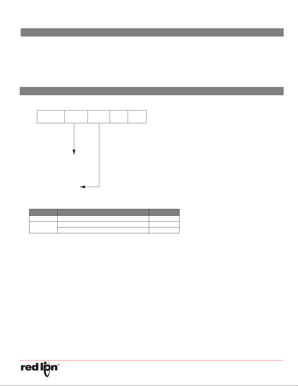
TABLE OFCONTENTS
PAXL
0
I - Current Input
V - Voltage Input
0
A - AC Input
D - DC Input
Ordering Information.................................................................2
General Meter Specifications.................................................... 3
Accessories ..............................................................................3
Installing the Meter ...................................................................4
Setting the Jumpers and Switches ........................................... 4
ORDERINGINFORMATION
MeterPartNumbers
Wiring the Meter ........................................................................5
Scaling the Meter ......................................................................6
Troubleshooting.........................................................................7
Calibration .................................................................................7
AccessoriesPartNumbers
MODEL NO. DESCRIPTION PART NUMBER
PAXLBK Units Label Kit Accessory PAXLBK30
APSCM
10 Amp DC Current Shunt APSCM010
100 Amp DC Current Shunt APSCM100
-2-
Page 3

GENERALMETERSPECIFICATIONS
1. DISPLAY: 3 1/2-digit, 0.56" (14.2 mm) high, 7-segment red LED, (-)
minus sign displayed when current or voltage is negative. Decimal
points inserted before 1st, 2nd, or 3rd least significant digits by DIP
switch selection.
2. POWER: 115/230 VAC, switch selectable. Allowable power line
variation ±10%, 50/60 Hz, 6 VA.
Isolation: 2300 Vrms for 1 min. between input and supply
Working Voltage: 300 V max. , CAT II
3. INPUT RANGE/RESOLUTION: (Selectable by jumper connections.):
Input Impedance:
Voltage: All ranges 1M
Current: 199.9 µA 1000.1 K
1.999 mA 100.1
19.99 mA 10.1
199.9 mA 1.1
1.999 A 0.1
Working Voltage: 300 V max., CAT II
4. ACCURACY:
AC Voltmeters: ±(0.1% of Reading + 3 digits) (45-500 Hz)
AC Current Meters (45-500 Hz):
199.9 µA/199.9 mV, 1.999 mA, 19.99 mA: ±(0.1% of Reading + 3
digits)
199.9 mA: ±(0.15% of Reading + 3 digits)
1 A: ±(0.5% of Reading + 3 digits)
DC Voltmeters: ±(0.1% of Reading + 1 digit)
DC Current Meters:
199.9 µA/199.9 mV, 1.999 mA, 19.99 mA: ±(0.1% of Reading + 1
digit)
199.9 mA: ±(0.15% of Reading + 1 digit)
1.999 A: ±(0.5% of Reading + 1 digit)
Note: Any individual range may be recalibrated (scaled) to 0.1%
accuracy with appropriate calibration equipment.
5. OVER-RANGE INDICATION: on all modes is indicated by blanking 3
least significant digits.
6. MAX. VOLTAGE ON LOWEST INPUT RANGE: 75 VAC or DC (Both
voltmeters and current meters).
7. MAX. VOLTAGE ON TERMINAL BLOCK: 300 VAC or DC (Both
voltmeters and current meters).
8. MAX. CURRENTS (FOR CURRENT METERS):
199.9 µA through 19.99 mA: 10 times max. range current
199.9 mA: 1 A
1.999 A: 3 A
Caution: In circuits where fault currents can exceed the maximum
shunt current, a fast-blow fuse should be installed in series with the
input signal. Otherwise, a slow blow 10 amp fuse is recommended
that will allow for start-up over current situations, while still protecting
the instrument.
9. TEMPERATURE COEFFICIENTS:
Current meters Voltmeters
DC: 100 PPM/°C DC: 75 PPM/°C
AC:
10.ENVIRONMENTAL CONDITIONS:
Operating Temperature: 0° to 60 °C
Storage Temperature: -40° to 80 °C
Operating and Storage Humidity: 85% max. relative humidity (non-
Vibration to IEC 68-2-6: Operational 5 to 150 Hz, 2 g.
Shock to IEC 68-2-27: Operational 30 g.
Altitude: Up to 2000 meters
11.RESPONSE TIME TO STEP CHANGE INPUT: 1 sec. nominal
12.READING RATE: 2.5 readings/sec., nominal
13.NORMAL MODE REJECTION: 50 dB 50/60 Hz (DC units only)
14.COMMON MODE REJECTION: 110 dB DC or 50/60 Hz (DC units
only)
15.COMMON MODE VOLTAGE (COMM. TO EARTH): 350 volt peak
16.CERTIFICATIONS AND COMPLIANCES:
CE Approved
Safety requirements for electrical equipment for measurement, control,
RoHS Compliant
UL Listed: File #E137808
Type 4X Enclosure rating (Face only)
IP65 Enclosure rating (Face only)
IP20 Enclosure rating (Rear of unit)
17.CONNECTIONS: High compression cage-clamp terminal block
Wire Strip Length: 0.3" (7.5 mm)
Wire Gage: 30-14 AWG copper wire
Torque: 4.5 inch-lbs (0.51 N-m) max.
18.CONSTRUCTION: This unit is rated for Type 4X/IP65 outdoor use.
Installation Category II, Pollution Degree 2. One piece bezel/case.
Flame resistant. Panel gasket and mounting clip included.
19.WEIGHT: 0.65 lbs. (0.24 Kg)
200 PPM/°CAC: 150 PPM/°C
condensing)
EN 61326-1 Immunity to Industrial Locations
Emission CISPR 11 Class B
and laboratory use:
EN 61010-1: General Requirements
EN 61010-2-030: Particular Requirements for Testing and
Measuring Circuits
ACCESSORIES
UNITS LABEL KIT (PAXLBK)
Each meter has a units indicator with backlighting that can be
customized using the Units Label Kit. The backlight is controlled by a DIP
switch.
EXTERNAL CURRENT SHUNTS (APSCM)
To measure DC current signals greater than 2 ADC, a shunt must be
used. The APSCM010 current shunt converts a maximum 10 ADC signal
into 100.0 mV. The APSCM100 current shunt converts a maximum 100
ADC signal into 100.0 mV. The continuous current through the shunt is
limited to 115% of the rating.
-3-
Page 4

LATCHING
TABS
PANEL
LATCH
PANEL
MOUNTING
SCREWS
LATCHING
SLOTS
PANEL
GASKET
BEZEL
PANEL
-.00
(92 )
-.0
+.8
3.62
+.03
(45 )
1.77
-.0
+.5
-.00
+.02
ONLY ONE
THIS AREA!
JUMPER IN
CURRENT
REAR TERMINALS
±1.999A
/199.9mV
±199.9μA
±199.9mA
±19.99mA
±1.999mA
INPUT RANGE JUMPER
Main
Circuit
Board
SET-UP
DIP
SWITCHES
POWER SELECTION SWITCH
INPUT
RANGE
JUMPER
SCALING
POT
230
115
3
5
4
1
2
ON
1.0INSTALLINGTHEMETER
INSTALLATION
The PAX meets NEMA 4X/IP65 requirements when properly installed.
The unit is intended to be mounted into an enclosed panel. Prepare the
panel cutout to the dimensions shown. Remove the panel latch from the
unit. Slide the panel gasket over the rear of the unit to the back of the
bezel. The unit should be installed fully assembled. Insert the unit into the
panel cutout.
While holding the unit in place, push the panel latch over the rear of the
unit so that the tabs of the panel latch engage in the slots on the case.
The panel latch should be engaged in the farthest forward slot possible.
To achieve a proper seal, tighten the latch screws evenly until the unit is
snug in the panel (Torque to approximately 7 in-lbs [79N-cm]). Do not
over-tighten the screws.
INSTALLATIONENVIRONMENT
The unit should be installed in a location that does not exceed the
maximum operating temperature and provides good air circulation.
Placing the unit near devices that generate excessive heat should be
avoided.
The bezel should be cleaned only with a soft cloth and neutral soap
product. Do NOT use solvents. Continuous exposure to direct sunlight
may accelerate the aging process of the bezel.
2.0SETTINGTHEJUMPERSANDSWITCHES
The meter has an input jumper and switches, which must be checked
and/or changed prior to applying power. To access the input jumper and
switches, remove the meter base from the case by firmly squeezing and
pulling back on the side rear finger tabs. This should lower the latch below
the case slot (which is located just in front of the finger tabs). It is
recommended to release the latch on one side, then start the other side
latch.
Power Selection Switch
Caution: Insure the AC power selection switch is set for the
proper voltage before powering the meter. The meter is
shipped from the factory in the 230 VAC position.
Input Range Jumper
A jumper is used for selection of the voltage or current input range.
Select the proper input range that will be high enough to avoid input signal
overload. It is important that only one jumper position is used at a time.
Avoid placing a jumper across two different input ranges.
Set-Up DIP Switches
A DIP switch is located inside the meter. It is used for the selection of
decimal points, backlight annunciator, and scaling. Selecting the “ON”
position enables the function.
SWITCH FUNCTION
1 Decimal Point 1 (000.0)
2 Decimal Point 2 (00.00)
3 Decimal Point 3 (0.000)
4 Backlight Annunciator for Units Label
5 Enables the Scaling Pot
* Turn scaling pot fully clockwise (25 turns max.) when scaling is
disabled. Factory setting is the fully clockwise position.
PANEL CUT-OUT
PAXLIJumperSelection
JUMPER SELECTIONS
The indicates factory setting.
FRONT DISPLAY
REAR TERMINALS
-4-
Page 5

PAXLVJumperSelection
ONLY ONE
THIS AREA!
JUMPER IN
REAR TERMINALS
VOLT
±300V
±199.9V
±19.99V
±1.999V
INPUT RANGE JUMPER
Main
Circuit
Board
SET-UP
DIP
SWITCHES
POWER
SELECTION
SWITCH
INPUT RANGE
JUMPER
SCALING
POT
230
115
REAR TERMINALS
FRONT DISPLAY
3
5
4
1
2
ON
JUMPER SELECTIONS
The indicates factory setting.
3.0WIRINGTHEMETER
WIRINGOVERVIEW
Electrical connections are made via screw-clamp terminals located on
the back of the meter. All conductors should conform to the meter’s
voltage and current ratings. All cabling should conform to appropriate
standards of good installation, local codes and regulations. It is
recommended that power supplied to the meter (AC) be protected by a
fuse or circuit breaker.
When wiring the meter, compare the numbers embossed on the back
of the meter case against those shown in wiring drawings for proper wire
position. Strip the wire, leaving approximately 0.3" (7.5 mm) bare lead
exposed (stranded wires should be tinned with solder). Insert the lead
under the correct screw-clamp terminal and tighten until the wire is
secure. (Pull wire to verify tightness.)
EMCINSTALLATIONGUIDELINES
Although Red Lion Controls Products are designed with a high degree
of immunity to Electromagnetic Interference (EMI), proper installation and
wiring methods must be followed to ensure compatibility in each
application. The type of the electrical noise, source or coupling method
into a unit may be different for various installations. Cable length, routing,
and shield termination are very important and can mean the difference
between a successful or troublesome installation. Listed are some EMI
guidelines for a successful installation in an industrial environment.
1. A unit should be mounted in a metal enclosure, which is properly
connected to protective earth.
2. Use shielded cables for all Signal and Control inputs. The shield
connection should be made as short as possible. The connection point
for the shield depends somewhat upon the application. Listed below
are the recommended methods of connecting the shield, in order of
their effectiveness.
a. Connect the shield to earth ground (protective earth) at one end
where the unit is mounted.
b. Connect the shield to earth ground at both ends of the cable, usually
when the noise source frequency is over 1 MHz.
3. Never run Signal or Control cables in the same conduit or raceway with
AC power lines, conductors, feeding motors, solenoids, SCR controls,
and heaters, etc. The cables should be run through metal conduit that
is properly grounded. This is especially useful in applications where
cable runs are long and portable two-way radios are used in close
proximity or if the installation is near a commercial radio transmitter.
Also, Signal or Control cables within an enclosure should be routed as
far away as possible from contactors, control relays, transformers, and
other noisy components.
4. Long cable runs are more susceptible to EMI pickup than short cable
runs.
5. In extremely high EMI environments, the use of external EMI
suppression devices such as Ferrite Suppression Cores for signal and
control cables is effective. The following EMI suppression devices (or
equivalent) are recommended:
Fair-Rite part number 0443167251 (RLC part number FCOR0000)
Line Filters for input power cables:
Schaffner # FN2010-1/07 (Red Lion Controls # LFIL0000)
6. To protect relay contacts that control inductive loads and to minimize
radiated and conducted noise (EMI), some type of contact protection
network is normally installed across the load, the contacts or both. The
most effective location is across the load.
a. Using a snubber, which is a resistor-capacitor (RC) network or metal
oxide varistor (MOV) across an AC inductive load is very effective at
reducing EMI and increasing relay contact life.
b. If a DC inductive load (such as a DC relay coil) is controlled by a
transistor switch, care must be taken not to exceed the breakdown
voltage of the transistor when the load is switched. One of the most
effective ways is to place a diode across the inductive load. Most
RLC products with solid state outputs have internal zener diode
protection. However external diode protection at the load is always a
good design practice to limit EMI. Although the use of a snubber or
varistor could be used.
RLC part numbers: Snubber: SNUB0000
Varistor: ILS11500 or ILS23000
7. Care should be taken when connecting input and output devices to the
instrument. When a separate input and output common is provided,
they should not be mixed. Therefore a sensor common should NOT be
connected to an output common. This would cause EMI on the
sensitive input common, which could affect the instrument’s operation.
Visit RLC’s web site at http://www.redlion.net/emi for more information
on EMI guidelines, Safety and CE issues as they relate to Red Lion
Controls products.
-5-
Page 6

3.1POWERWIRING
1 2
AC
115/230
AC
3 4
V
-
+
300V MAX.
INPUT
COMM
3 4
A
-
+
2A MAX.
COMM
INPUT
1K
9K
90K
900K
0-1.999V
0-19.99V
0-199.9V
0-300V
PROCESS
CIRCUITRY
+VDC
SCALE
POT
S5
S3 S2 S1
+SIGNAL
COMMON
S4
3.2INPUTSIGNALWIRING
Before connecting signal wires, the Input Range Jumper should be verified for proper position.
AC Power
Terminal 1: VAC
Terminal 2: VAC
PAXLV
Voltage Signal (self powered)
Terminal 4: + Volts DC/AC
Terminal 3: - Volts DC/AC
4.0SCALINGTHEMETER
PAXLV
DIRECT VOLTMETER READOUT
When the application requires direct voltmeter readout, the Scale
Switch should be set in the “OFF” position and the Input Range Jumper
set to the voltage range being applied. To reduce display resolution, the
jumper can be set to a higher range than the input range being applied.
Set the Decimal Point switches according to the resolution of the selected
Input Range.
SCALING VOLTMETER READOUT
In many industrial applications, a voltmeter is required to display a
reading in terms of PSI, RPM, or some other unit of measure. The voltage
signal being measured can be generated by a transducer that senses the
variations and delivers a linear output voltage. To provide the desired
readout at the specified voltage, the voltmeter must be scaled.
Place the Scale Switch in the “ON” position. This enables the Scale
Potentiometer which is accessible from the back of the meter. (Enabling
the Scale Potentiometer does NOT affect the calibration of the meter.)
Place the Decimal Point Switches to the proper location. To properly set
the Input Range Jumper, the Division Factor must be determined by first
using the below formula. After the Division Factor is calculated, use the
Division Factor Range Selection Chart to choose the proper Input Range
Jumper setting. Apply the meter power and the voltage signal. Adjust the
Scale Potentiometer to the desired value.
This scaling only effects the span. There is no offset scaling. This
means that only zero voltage input can produce a display value of zero.
DIVISION FACTOR FORMULA:
VT x D.D.P.
D.R.
= D.F.
PAXLI
Current Signal (self powered)
Terminal 4: + Amps DC/AC
Terminal 3: - Amps DC/AC
proper voltage range jumper can be selected. Use the “Division Factor
Range Selection Chart” to choose the proper jumper setting.
DIVISION FACTOR RANGE SELECTION CHART
D.F. Use Input Position
0.1 to 1.2 Pos 1: 0-1.999 VDC
1.2 to 10.5 Pos 2: 0-19.99
10.5 to 100.5 Pos 3: 0-199.9
100.5 to 1300 Pos 4: 0-300
Note: Only one voltage jumper should be selected. Install the jumper
before the voltage signal is applied.
BLOCK DIAGRAM PAXLV
WHERE:
VT = Maximum Transducer Output
D.D.P = Display Decimal Point
D.F. = Division Factor
D.R. = Desired Reading (without regard for decimal point)
Display of x.xxx = D.R. of xxxx
D.D.P.
0.000 = 1 The Display Decimal Point
00.00 = 10 (D.D.P.) is determined by
000.0 = 100 the desired decimal point
After the Division Factor for the application has been calculated, the
0000 = 1000 placement in the readout.
EXAMPLE: A relative humidity transducer delivers a 7.0 VDC voltage at a
relative humidity of 75%.
VT x D.D.P.
D.F. =
D.R. 75
= 7.0 x 1000
= 93.3
This Division Factor is between 10.5 and 100.5, therefore jumper
position 3 (199.9 V) is selected. The Scaling Potentiometer is then
adjusted for the desired readout at a known relative humidity.
-6-
Page 7

PAXL I
PROCESS
CIRCUITRY
+VDC
S3 S2 S1 S4
COMMON
+SIGNAL
0-199.9mA
0-19.99mA
1 :
9 :
S5
0-1.999mA
0-199.9μA/
90 :
900 :
POT
SCALE
.1 :
0-1.999A
199.9mV
DIRECT CURRENT METER READOUT
When the application requires direct current meter readout, the Scale
Switch should be set in the “OFF” position and the Input Range Jumper
set to the current range being applied. To reduce display resolution, the
jumper can be set to a higher range than the input range being applied.
Set the Decimal Point switches according to the resolution of the selected
Input Range.
SCALING CURRENT METER READOUT
In many industrial applications, a current meter is required to display a
reading in terms of PSI, RPM, or some other unit of measure. The current
signal being measured can be generated by a transducer that senses the
variations and delivers a linear output current. To provide the desired
readout at the specified current, the current meter must be scaled.
Place the Scale Switch in the “ON” position. This enables the Scale
Potentiometer which is accessible from the back of the meter. (Enabling
the Scale Potentiometer does NOT affect the calibration of the meter.)
Place the Decimal Point Switches to the proper location. The Input Range
Jumper is set to the current range being applied. Apply the meter power
and the current signal. Adjust the Scale Potentiometer to the desired
value. Scaling to obtain a numerical readout higher than the normal value
of the current can also be accomplished, in most cases, by selecting a
lower current range. However, the maximum current for the range must
not be exceeded. (See Specifications for maximum input currents.)
This scaling only effects the span. There is no offset scaling. This
means that only zero current input can produce a display value of zero.
BLOCK DIAGRAM PAXLI
EXAMPLE: The PAX Current Meter has been connected to measure a
circuit current to 120.0 mA maximum. However, in this application, the
display is to indicate percent of load current with 120.0 mA equivalent
to 100.0 percent. The scale potentiometer is adjusted to reduce the
normal 120.0 mA signal input display reading of 120.0 to indicate the
desired reading of 100.0 on the display. Scaling to obtain a numerical
readout higher than the normal value of the current can also be
accomplished in most cases by selecting a lower current range.
However, the maximum current for the range must not be exceeded.
(See Specifications for maximum input currents.)
5.0TROUBLESHOOTING
PROBLEM REMEDIES
NO DISPLAY
INCORRECT DISPLAY
OVER-RANGE INDICATION
CHECK: Power switch and line voltage
CHECK: Input jumper position
CHECK: Scaling adjustment pot DIP switch position
ADJUST: Scaling pot
VERIFY: Input Signal
CHECK: Input jumper position
VERIFY: Input signal
6.0CALIBRATION
The meter has been fully calibrated at the factory. Scaling to convert
the input signal to a desired display value is performed by enabling the
scale pot DIP switch. If the meter appears to be indicating incorrectly or
inaccurately, refer to Troubleshooting before attempting to calibrate the
meter.
When recalibration is required (generally every 2 years), it should only
be performed by qualified technicians using appropriate equipment.
Input Calibration
WARNING: Calibration of this meter requires a signal source
with an accuracy of 0.01% or better and an external meter
with an accuracy of 0.005% or better.
Before starting, verify that the Input Range Jumper is set for the range
to be calibrated. Also verify that the precision signal source is connected
and ready. Allow a 30 minute warm-up period before calibrating the
meter.
Then perform the following procedure:
1. Place jumper in 2 V range (PAXLV) or 2 mA range (PAXLI).
2. Set the DIP switch off to disable the scaling pot.
3. Apply half scale input signal.
4. Adjust calibration potentiometer as necessary for the display to read
1000 (ignore decimal point).
5. Apply zero signal and ensure display reads zero.
6. Apply full scale signal and ensure display reads 1999.
Note: Any individual range may be recalibrated to 0.1% accuracy with
appropriate calibration equipment.
-7-
 Loading...