

Page 1
1
2
3
4
5
6
7
8
9
10
11
3.60 (91.4)
(44.5)
1.75
(96.5)
3.80
1.95
(49.5)
(2.5)
.10
(104.1)
4.10
(44.5)
1.75
1.8.8.8
mV
Tel +1 (717) 767-6511
C
US LISTED
Fax +1 (717) 764-0839
www.redlion.net
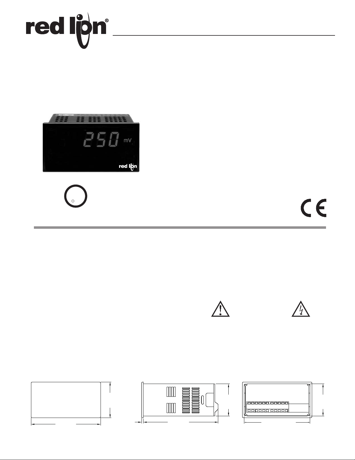
MODEL PAXLSG - PAX LITE STRAIN GAGE METER /
MILLIVOLT METER
3 1/2-DIGIT, 0.56" (14.2 MM) HIGH RED LED READOUT
HIGH SENSITIVITY, 10 MV FULL SCALE
WIDE RANGE GAIN AND OFFSET ADJUSTMENTS
BUILT-IN EXCITATION 5 OR 10 VDC
APPLICABLE AS REGULAR MILLIVOLT INDICATOR
(SINGLE-ENDED OR DIFFERENTIAL INPUT)
SELECTABLE DECIMAL POINTS
OVER-RANGE INDICATION
NEMA 4X/IP65 SEALED FRONT BEZEL
OPTIONAL CUSTOM UNITS OVERLAY WITH BACKLIGHT
Bulletin No. PAXLSG-B
Drawing No. LP0571
Released 01/12
U
R
C
L
US LISTED
IND. CONT. EQ.
51EB
GENERAL DESCRIPTION
The Model P AXLSG expands the PAX Lite capabilities into the indication of
pressure, load, force, and other parameters measured with strain gages. The unit
features broad range scaling and can be used with a wide variety of strain gage
resistances and bridge configurations. A built-in excitation source is jumper
selectable for 5 or 10 VDC @ 120 mA maximum, and can power up to four full
350 bridges in load averaging applications. Although designed primarily for
strain-gage indication, the P AXLSG is also ideal for single-ended or dif ferential
millivolt input applications, with full-scale input ranges from 0 to 10 mV thru 0
to 2 VDC. Adjustable scaling and offset allow direct readout in nearly any
engineering unit.
The meter has a NEMA 4X/IP65 sealed bezel and extensive testing of noise
effects to CE requirements, allowing the meter to provide a tough yet reliable
application solution.
DIMENSIONS In inches (mm)
Note: Recommended minimum clearance (behind the panel) for mounting clip installation is
2.1" (53.4) H x 5.0" (127) W.
SAFETY SUMMARY
All safety related regulations, local codes and instructions that appear in the
literature or on equipment must be observed to ensure personal safety and to
prevent damage to either the instrument or equipment connected to it. If
equipment is used in a manner not specified by the manufacturer, the protection
provided by the equipment may be impaired.
CAUTION: Risk of Danger.
Read complete instructions prior to
installation and operation of the unit.
CAUTION: Risk of electric shock.
1
Page 2
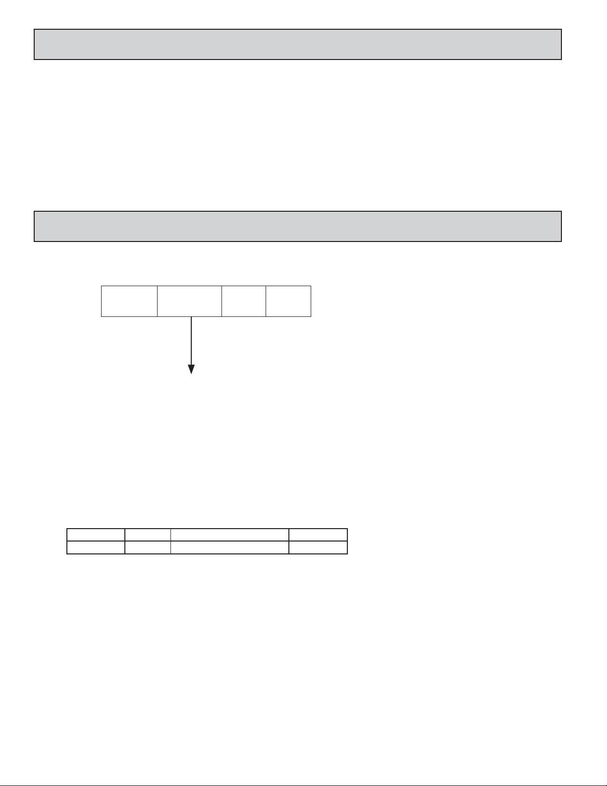
TABLE OF CONTENTS
Ordering Information . . . . . . . . . . . . . . . . . . . .2
General Meter Specifications . . . . . . . . . . . . .3
Accessories . . . . . . . . . . . . . . . . . . . . . . . . . . .3
Installing the Meter . . . . . . . . . . . . . . . . . . . . . 4
Setting the Jumpers and Switches . . . . . . . . . 4
ORDERING INFORMATION
Meter Part Numbers
PAXL
SG
0
Wiring the Meter . . . . . . . . . . . . . . . . . . . . . . . 5
Scaling the Meter . . . . . . . . . . . . . . . . . . . . . .6
Calibrating the Meter . . . . . . . . . . . . . . . . . . . .7
Applications . . . . . . . . . . . . . . . . . . . . . . . . . . .8
0
SG - Strain Gage Meter
Accessories Part Numbers
TYPE MODEL NO. DESCRIPTION PART NUMBERS
Accessories PAXLBK Units Label Kit Accessory PAXLBK30
2
Page 3

GENERAL METER SPECIFICATIONS
1. DISPLAY: 3 1/2-digit, 0.56" (14.2 mm) high, 7-segment red LED, (-) minus
sign displayed when voltage is negative. Decimal points inserted before 1st,
2nd, or 3rd least significant digits by DIP switch selection.
2. OVER-RANGE INDICATION: Indicated by blanking 3 least significant
digits.
3. POWER:
AC Power: 85 to 250 VAC, 50/60 HZ, 6 VA
Isolation: 2300 Vrms for 1 min. to all inputs.
4. INPUT SIGNAL: Single-ended or differential input, ±2.0 V max. Gain
(Sensitivity) is adjustable from 200 Units of Numerical Readout/millivolt input
(gives full scale readout of 1999 at 10 mV input), to less than 1 Unit of
Numerical Readout/mV (gives full scale readout of 1999 at 2.0 V input).
Maximum common mode voltage swing with respect to signal ground, 0 to 7 V.
Note: Absolute maximum voltage that can be applied between the two input
terminals or between input and signal common is 50 VDC.
5. INPUT IMPEDANCE: 100 M
6. LINEARITY: ±(0.05% ±1 digit)
7. LOW FREQUENCY NOISE REJECTION:
Normal Mode Rejection: 84 dB @ 50/60 Hz
Common Mode Rejection: 50 dB with respect to excitation common;
110 dB with respect to earth ground.
8. RESPONSE TIME: 2.0 seconds to settle from step input.
9. READING RATE: 2.5 updated readings/second, nominal.
10. EXCITATION SUPPLY:
Jumper Selectable: 5 VDC @ 60 mA max., ±2%
10 VDC @ 120 mA max., ±2%
Temperature coefficient (ratio metric): 20 ppm/°C max.
11. ENVIRONMENTAL CONDITIONS:
Operating Temperature: 0° to 60°C
Storage Temperature: -40° to 80°C
Operating and Storage Humidity: 85% max. relative humidity (non-
condensing)
Span Temperature Coeff.: 100 PPM/°C
Offset Temperature Coeff.: 100 PPM/°C
Vibration According to IEC 68-2-6: Operational 5 to 150 Hz, in X, Y, Z
direction for 1.5 hours, 2g.
Shock According to IEC 68-2-27: Operational 30 g, 11 msec in 3 directions.
Altitude: Up to 2000 meters
12. CERTIFICA TIONS AND COMPLIANCES:
SAFETY
UL Recognized Component, File # E179259, UL61010A-1, CSA C22.2 No. 61010-1
Recognized to U.S. and Canadian requirements under the Component
Recognition Program of Underwriters Laboratories, Inc.
UL Listed, File # E137808, UL508, CSA C22.2 No. 14-M95
LISTED by Und. Lab. Inc. to U.S. and Canadian safety standards
Type 4X Enclosure rating (Face only), UL50
IECEE CB Scheme Test Certificate # UL/8843A/UL
CB Scheme Test Report # 04ME11209-20041018
Issued by Underwriters Laboratories, Inc.
IEC 61010-1, EN 61010-1: Safety requirements for electrical equipment
for measurement, control, and laboratory use, Part 1.
IP65 Enclosure rating (Face only), IEC 529
IP20 Enclosure rating (Rear of unit), IEC 529
ELECTROMAGNETIC COMPATIBILITY
Emissions and Immunity to EN 61326: Electrical Equipment for
Measurement, Control and Laboratory use.
Immunity to Industrial Locations:
Electrostatic discharge EN 61000-4-2 Criterion A
4 kV contact discharge
8 kV air discharge
Electromagnetic RF fields EN 61000-4-3 Criterion B
10 V/m
Fast transients (burst) EN 61000-4-4 Criterion B
2 kV power
2 kV signal
Surge EN 61000-4-5 Criterion A
1 kV L-L,
2 kV L&N-E power
1 kV signal
RF conducted interference EN 61000-4-6 Criterion A
3 V/rms
Power frequency magnetic fields EN 61000-4-8 Criterion A
30 A/m
Voltage dip/interruptions EN 61000-4-11 Criterion A
0.5 cycle
Emissions:
Emissions EN 55011 Class B
Notes:
1. Criterion A: Normal operation within specified limits.
2. Criterion B: Temporary loss of performance from which the unit self-
recovers.
13. CONNECTIONS: High compression cage-clamp terminal block
Wire Strip Length: 0.3" (7.5 mm)
Wire Gage: 30-14 AWG copper wire
Torque: 4.5 inch-lbs (0.51 N-m) max.
14. CONSTRUCTION: This unit is rated for NEMA 4X/IP65 outdoor use.
IP20 Touch safe. Installation Category II, Pollution Degree 2. One piece
bezel/case. Flame resistant. Panel gasket and mounting clip included.
15. WEIGHT: 0.65 lbs (0.24 kg)
ACCESSORIES
UNITS LABEL KIT (PAXLBK)
Each meter has a units indicator with backlighting that can be customized
using the Units Label Kit. The backlight is controlled by a DIP switch.
3
Page 4

Main
Circuit
Board
D.P./ BACKLIGHT
REAR TERMINALS
FRONT DISPLAY
4
3
2
1
ON
OFFSET
SPAN
ON
123456789
OFFSET
GAIN
EXCITATION
SELECT
COARSE
FINE
1.0 INSTALLING THE METER
-.00
(92 )
-.0
+.8
3.62
+.03
(45 )
1.77
-.0
+.5
-.00
+.02
Installation
The PAX meets NEMA 4X/IP65 requirements when properly installed. The
unit is intended to be mounted into an enclosed panel. Prepare the panel cutout
to the dimensions shown. Remove the panel latch from the unit. Slide the panel
gasket over the rear of the unit to the back of the bezel. The unit should be
installed fully assembled. Insert the unit into the panel cutout.
PANEL
BEZEL
While holding the unit in place, push the panel latch over the rear of the unit
so that the tabs of the panel latch engage in the slots on the case. The panel latch
should be engaged in the farthest forward slot possible. T o achieve a proper seal,
tighten the latch screws evenly until the unit is snug in the panel (Torque to
approximately 7 in-lbs [79N-cm]). Do not over-tighten the screws.
Installation Environment
The unit should be installed in a location that does not exceed the maximum
operating temperature and provides good air circulation. Placing the unit near
devices that generate excessive heat should be avoided.
The bezel should be cleaned only with a soft cloth and neutral soap product.
Do NOT use solvents. Continuous exposure to direct sunlight may accelerate the
aging process of the bezel.
PANEL
GASKET
LATCHING
SLOTS
PANEL
LATCH
PANEL
MOUNTING
SCREWS
LATCHING
TABS
PANEL CUT-OUT
2.0 SETTING THE SWITCHES AND JUMPERS
The meter has switches that must be checked and/or changed prior to
applying power. To access the switches, remove the meter base from the case by
firmly squeezing and pulling back on the side rear finger tabs. This should lower
the latch below the case slot (which is located just in front of the finger tabs). It
is recommended to release the latch on one side, then start the other side latch.
Excitation Range Jumper
A jumper is used for selection of the 5 or 10 volt range. It is important that
only one jumper position is used at a time.
Set-Up DIP Switches
Two banks of DIP switches are located inside the meter. The 9 position bank
of switches is used for calibrating the meter. The values of these switches is
discussed in section 5.0 Calibrating the Meter.
The bank of 4 switches located near the front display are used for the
selection of decimal points and backlight annunciator. Selecting “ON” position
enables the function.
Decimal Point 1 (000.0)1
Decimal Point 2 (00.00)2
Decimal Point 3 (0.000)3
Backlight Annunciator for Units Label4
FUNCTIONSWITCH
PAXLSG Jumper Selection
JUMPER SELECTIONS
The indicates factory setting.
REAR TERMINALS
EXCITATION SELECT
10V
5V
4
Page 5

4 5 6
+
- SIG
+ SIG
COMM
3
-
+ EXC
3.0 WIRING THE METER
1 2
AC
AC
85-250 VAC
WIRING OVERVIEW
Electrical connections are made via screw-clamp terminals located on the
back of the meter. All conductors should conform to the meter’s voltage and
current ratings. All cabling should conform to appropriate standards of good
installation, local codes and regulations. It is recommended that power supplied
to the meter (AC) be protected by a fuse or circuit breaker.
When wiring the meter, compare the numbers embossed on the back of the
meter case against those shown in wiring drawings for proper wire position. Strip
the wire, leaving approximately 0.3" (7.5 mm) bare lead exposed (stranded wires
should be tinned with solder). Insert the lead under the correct screw-clamp
terminal and tighten until the wire is secure. (Pull wire to verify tightness.)
EMC INSTALLATION GUIDELINES
Although this meter is designed with a high degree of immunity to ElectroMagnetic Interference (EMI), proper installation and wiring methods must be
followed to ensure compatibility in each application. The type of the electrical
noise, its source or the method of coupling into the unit may be different for
various installations. Listed below are some EMC guidelines for successful
installation in an industrial environment.
1. The meter should be mounted in a metal enclosure, which is properly
connected to protective earth.
2. Never run Signal or Control cables in the same conduit or raceway with AC
power lines, conductors feeding motors, solenoids, SCR controls, and
heaters, etc. The cables should be run in metal conduit that is properly
grounded. This is especially useful in applications where cable runs are long
3.1 POWER WIRING
and portable two-way radios are used in close proximity or if the installation
is near a commercial radio transmitter.
3. Signal or Control cables within an enclosure should be routed as far away as
possible from contactors, control relays, transformers, and other noisy
components.
4. In extremely high EMI environments, the use of external EMI suppression
devices, such as ferrite suppression cores, is effective. Install them on Signal
and Control cables as close to the unit as possible. Loop the cable through the
core several times or use multiple cores on each cable for additional protection.
Install line filters on the power input cable to the unit to suppress power line
interference. Install them near the power entry point of the enclosure. The
following EMI suppression devices (or equivalent) are recommended:
Ferrite Suppression Cores for signal and control cables:
Fair-Rite # 0443167251 (RLC #FCOR0000)
TDK # ZCAT3035-1330A
Steward #28B2029-0A0
Line Filters for input power cables:
Schaffner # FN2010-1/07 (RLC #LFIL0000)
Schaffner # FN670-1.8/07
Corcom #1VR3
Note: Reference manufacturer’s instructions when installing a line filter.
5. Long cable runs are more susceptible to EMI pickup than short cable runs.
Therefore, keep cable runs as short as possible.
6. Switching of inductive loads produces high EMI. Use of snubbers across
inductive loads suppresses EMI.
Snubber: RLC#SNUB0000.
AC Power
Terminal 1: VAC
Terminal 2: VAC
3.2 INPUT SIGNAL WIRING
2-Wire Single Ended Input
4-Wire Bridge Input
COMM
Excitation Power
Terminal 3: Common
Terminal 4: Excitation +
+EXC
+SIG
5 6
43
+EXC.
+SIG.
-EXC.
-SIG.
-SIG
COMM.
3
BRIDGE
-EXC.
5 VDC @ 60 mA max, ±2%
10 VDC @ 120 mA max, ±2%
+EXC.
4
+EXC.
6-Wire Bridge Input
+EXC
COMM
+EXC.
+SIG
+SEN
+SIG.
-SEN
-EXC.
-SIG
643 5
-SIG.
DEADLOAD COMPENSATION
In some cases, the combined deadload and liveload output may exceed the
range of the input. To use this range, the output of the bridge can be offset a
small amount by applying a fixed resistor across one arm of the bridge. This
shifts the electrical output of the bridge downward to within the operating range
of the meter. A 100 K ohm fixed resistor shifts the bridge output approximately
-10 mV (350 ohm bridge, 10 V excitation).
Connect the resistor between +SIG and -SIG. Use a metal film resistor with
a low temperature coefficient of resistance.
BRIDGE COMPLETION RESISTORS
For single strain gage applications, bridge completion resistors must be
employed externally to the meter. Only use metal film resistors with a low
temperature coefficient of resistance.
Load cells and pressure transducers are normally implemented as full
resistance bridges and do not require bridge completion resistors.
5
Page 6

K1
.77K
S1
68.1K
2.2K
7.15K
22.6K
(+)
(-)
50K
S3 S2 S1
DIGITAL DISPLAY
S8
S7
S6
S5
S9
140 U/MV
50 U/MV
16 U/MV
6.6 U/MV
3.3 U/MV
K3
K2
30K 30K
30K30K
5
6
30K
30K
CW5KCW
45K
K4
30K
100K
S3
500
S2
200K
400K
250
125
S4
800K
DECIMAL POINT / BACKLIGHT
SWITCHES
DIGITAL VOLTMETER & DISPLAY
DRIVER CIRCUIT
COARSE OFFSET
SELECT SWS.
FINE OFFSET
ADJ.
+V -V
+SIG.
-SIG.
-EXC. +EXC.
(+)SIG.
(-)SIG.
GAIN COARSE
SELECT SWITCHES
COARSE GAIN
ADJ.
FINE GAIN ADJ.
+/-OFFSET
SELECT
5K
5K
S4
STRAIN GAGE
TRANSDUCER
5K
V
4.0 SCALING THE METER
PAXLSG SCHEMATIC
DESCRIPTION OF OPERATION
The Pax Lite Strain Gage Indicator (PAXLSG) consists of a digital voltmeter
combined with a high-gain, differential input amplifier that has provision for wide
range scaling adjustment (shown above). The unit also incorporates an excitation
power supply (5 or 10 VDC) that delivers up to 120 mA. In the simplified
schematic above, K1, K2, and K3 form a high-gain, high-stability, differential
input preamplifier with a single ended output. The gain of this preamplifier is set
up by coarse gain select switches S5 through S9. These switches can be turned on
in combination to provide discrete steps of gain-range adjustment. The output of
the preamplifier (K3 output) is applied to the summing amplifier (K4) through
coarse and fine adjustable potentiometers. These adjustable potentiometers
provide final vernier gain adjustment over a range of slightly more than 2:1. An
adjustable offset voltage signal is also added in at the input of K4 for zero-balance
or for applications where the transfer curve must be offset from zero.
GAIN ADJUSTMENTS
Gain is defined as the Units of Numerical change seen on the display per mV
(millivolt) of input signal change (disregarding display decimal points). In effect,
gain determines the slope of the transfer curve and is expressed in Units/mV.
GAIN = (Max. Num. Readout) - (Min. Num. Readout)
(Max. mV Input Sig.) - (Min. mV Input Sig.)
Note: Disregarded Decimal Points in Readout.
For example, if an PAXLSG is to display 50.0 @ 2 mV (min.) and 169.0 @
19 mV (max.), the required gain will be:
GAIN = 1690 Units - 500 Units
19 mV - 2 mV
Note: Remember, display decimal points are disregarded.
To establish this gain, the settings of the coarse gain select switches must first
be determined. These switches establish the maximum end of the 2:1 adjustment
range of the coarse and fine vernier gain adjustments.
= 70 Units/mV
COARSE GAIN SELECT SWITCHES
Each of the coarse gain select switches is marked with the amount of
maximum gain it will contribute when turned on. They are turned on singly or
in combination (adding up each of their gain contributions), to arrive at a
maximum gain value that is just above the desired gain value. To achieve the
desired gain of 70 Units/mV in the example just given, the following switches
would be turned on:
S6 (Gain 50) + S7 (Gain 16) + S8 (Gain 6.6) = 72.6 Units/mV
With these switches ON, the coarse and fine vernier adjustments cover a gain
range from about 36 Units/mV (½ of max.) to 72.6 Units/mV. The required gain
of 70 Units/mV falls within this adjustable range.
COARSE AND FINE GAIN ADJUSTMENTS
Once the gain select switches have been set, the final gain calibration is made
with the Coarse and Fine Gain adjustments. Both of these adjustments are
15-Turn, screwdriver adjustable potentiometers that increase gain with
clockwise rotation. The Coarse adjustment has a 2:1 range. The Fine adjustment
has a range of 5-10% (depending on the setting of the Coarse adjustment). Both
pots are located at the rear of the meter.
OFFSET ADJUSTMENTS
without changing the slope (Gain). They are used to “balance” the output of
transducers or to intentionally introduce an offset, such as tare-load compensation.
The Fine Offset Adjustment is a 15-turn screwdriver adjustable potentiometer,
located at the rear of the meter. It has a range of ±125 Numerical Units of offset
which is sufficient for balancing the output of most transducers.
of offset. Like the coarse gain select switches, the offset switches are marked
with the approximate value of offset contributed by each switch, and they can
be turned on in combinations with each switch, contributing its value to the
total. Switch S1 selects the polarity of the offset signal and can be set to either
add or subtract the offset contribution of the switches. The maximum offset that
can be obtained with all switches ON and the Fine Offset at its maximum is
±1000, which is one half of the full scale readout.
6
Offset adjustments move the transfer curve up-and-down along the vertical axis
The Coarse Offset Switches (S2, 3, and 4) can be used to add additional steps
Page 7

5.0 CALIBRATING THE METER
(-)
6
4
DUMMY
BRIDGE
350
Ω
1%
350
Ω
1%
8.0KΩ
R2
1KΩ
BRIDGE
BAL.
R1
1KΩ 10-T HIGH RESOLUTION
CAL. VOLTAGE ADJ.
POTENTIOMETER
ZERO
SWITCH
R3
40KΩ
(+)
5
REFERENCE
MILLIVOLT
METER
(+)
(-)
3
50/60 HZ
A.C. POWER
2
1
EXCITATION
VOLTAGE
SET AT 10VDC
SIGNAL
INPUT
PAXLSG
(+)
(-)
There are three different methods that can be used to calibrate the PAXLSG,
and the method chosen depends largely on the nature of the application. The
three methods are:
VOLTAGE CALIBRATION
In this method, the transducer signal is simply replaced with an accurately
measured input voltage that can be varied through the range normally delivered
by the transducer (See Voltage Calibration Circuit, below). The PAXLSG is then
adjusted to provide the proper readout.
SYSTEM CALIBRATION
In this method, the transducer is connected to the input of the P AXLSG in the
final installation, or in a bench set-up simulating the actual installation.
Accurately known inputs are then applied to the transducer (i.e. load, pressure,
force, etc.), and the PAXLSG adjustments are made to provide the desired
indication. This method is usually preferable to the Voltage Calibration method
since it calibrates both the transducer and the PAXLSG as a combination, and
reduces the inherent risk of inaccuracy or errors accumulated by separate
calibration. However, it can only be used in applications where the parameter to
be indicated can be easily varied and accurately measured or established. It is
also very awkward to use if an offset or transducer unbalance must be dealt with
because of Offset/Gain adjustment interaction.
COMBINATION VOLTAGE/SYSTEM CALIBRATION
In applications where tare-load, offset, or substantial transducer unbalance
exists and where high accuracy is required in the final indication, it may be
desirable to voltage calibrate the unit first to get it very close to its final settings.
Then, after final installation, the unit can be “tweaked” to its final settings while
using accurately known inputs to the system. These various factors make it
impossible to set up one calibration procedure to cover all applications.
However, using the following information on Voltage Calibration together with
the examples given should provide a good basis for handling virtually any
calibration requirement.
CALIBRATION EXAMPLE
“Voltage Calibration” can be easily performed for any application, using the
calibration circuit shown below.
VOLTAGE CALIBRATION CIRCUIT
(Using 350 Ohm Dummy Bridge)
This 350 Ohms “Dummy Bridge” circuit delivers calibration voltages in
ranges of 0 to ±22 mV, 0 to +44 mV, or 0 to -44 mV, depending on the setting
of R2. The range can be increased or decreased by adjusting the value of R3
(shown as 40 K). An accurate reference millivoltmeter is used to set up the
calibration voltage, and a “Zero Switch” facilitates balancing without
readjusting the calibration voltage. High-stability metalized resistors (1% tol.)
should be used. The use of a dummy bridge insures a common-mode voltage
during calibration that is very similar to that of the actual transducer.
SET-UP:
Before starting the procedure, the Input Swing Voltage (Vs), the Readout
Span (Rs) and the required GAIN must be determined.
WHERE:
Rs = (Max. Numerical Display) - (Min. Numerical Display) Disregard Decimal Points
Vs = (mV in @ Max. Display) - (mV in @ Min. Display)
GAIN = Rs = Units/mV
Vs
EXAMPLE: Readout is to be 5.00 Units @ 2 mV minimum, and 15.00 Units
@ 18 mV maximum. The transducer is a 350 strain-gage bridge requiring
10 VDC excitation.
Rs = 1500 - 500 = 1000 Units
Vs = 18 mV - 2 mV = 16 mV
GAIN = 1000 = 62.5 Units/mV
16
Note: While most strain gage readout applications are zero-based (i.e. zero
readout @ zero input) this example was intentionally chosen because it included
an offset reading at zero input. It will be used in the Calibration Procedure
below to illustrate the most convenient way to handle offset situations without
excessive interaction of gain and offset adjustments. If a zero-based example
had been given, the minimum readout and input voltage would have both been
zero. Rs and Vs would then simply be the maximum values of readout and input
voltage respectively, gain would just be the ratio of (Max. Readout/Max. Input
mV), and Steps 7 and 8 of the procedure below could be eliminated.
CALIBRATION PROCEDURE
1. Set the Coarse Gain Select Switches, S5 through S9 to establish a maximum
range just exceeding the required gain. Referring to the example given, the
required gain was calculated to be 62.5 Units/mV. Setting switches S6 and S7
ON gives 50 + 16 = 66 Units/mV, which is just above the required amount. The
following chart gives an approximate gain adjustment value for each switch:
SWITCH NUMBER SPAN VALUE
5
6
7 16
8 6.6
9 3.3
All offset switches, S2, 3, and 4, should be off.
2. Connect the unit to the Calibration Circuit as shown. Set the excitation
voltage range jumper to the 10 V position.
3. Place unit in the case and turn power on to the unit. Allow 10 minutes of
warm-up time for stabilization.
4. Close the “Zero Switch” of the calibration circuit to obtain zero input voltage.
Adjust the fine offset control to get a zero readout.
5. Open the “Zero Switch” of the calibrating circuit and set the input voltage to
the calculated swing voltage, Vs. (Vs is 16 mV in the example given.) Now,
adjust the Gain Coarse and Fine Controls to get a readout equal to the
Readout Span.
(Rs = 1000 Units in the example given.)
6. Repeat Step 4 and readjust zero if required. If zero readjustment was needed,
repeat Step 5, then back to Step 4, etc., until Zero and Rs readings are
acceptable.
*7. Set the calibration voltage to the minimum input level (2 mV in this
example). Record the meter reading (125 in this example). Power the meter
down and remove it from the case. Set the Coarse Offset Select Switches to
get the corresponding minimum readout (add the switch offset value(s) to the
recorded meter reading). In the example given, the minimum readout was
500 units @ 2 mV, therefore setting switches 3 and 4 gives us 125 (meter
reading) + 125 (SW4) + 250 (SW3) = 500. The following chart gives an
approximate offset adjustment value for each switch.
SWITCH NUMBER OFFSET VALUE
2 500
3 250
4 125
*8. Place unit in the case and turn power on to the unit. Use the fine offset
adjustment to fine tune the desired minimum reading (500 in this example).
Vary the input from the minimum to maximum levels and check the
corresponding readouts. Fine-tune if necessary by readjusting the fine gain
adjustment at the maximum end and the fine offset adjustment at the
minimum end. (In the example, readout is 500 @ 2 mV min. and 1500 @ 18
mV max.) Alternate between minimum and maximum inputs as required
until readout is within desired tolerance at the extremes.9. Set appropriate
decimal point switch (S2 for the example given).
The unit is now ready for installation.
* Steps 7 and 8 are not required in zero-based applications.
7
140
50
Page 8

6
4
5
3
PAXLSG
3, MATCHED LOAD CELLS
IN TRIPOD MOUNT
(-)EXC.
(+)EXC.
(+)SIG.
(-)SIG.
6.0 APPLICATIONS
6
4
5
3
POWER
A.C.
2
1
PAXLSG
(+) EXC.
(+) SIG.
(-) SIG.
(-) EXC.CIRCUIT COMMON
DIFF.
SIGNAL
CIRCUIT COMMON
(-) SIG.
6
(-) EXC.
(+) EXC.
(+) SIG.
5
4
3
2
POWER
A.C.
1
PAXLSG
+/- SIGNAL
(-)
6
4
(+)
5
3
2
1
EXCITATION
VOLTAGE
SET AT 10 VDC
SIGNAL
INPUT
PAXLSG
(+)
(-)
+EXC.
-SIG.
+SIG.
-EXC.
350 ± STRAIN GAGE BRIDGE
PRESSURE TRANSDUCER
0-20 MV OUTPUT AT 0-150 PSI
(10 V EXCITATION)
EXAMPLE #1 PRESSURE READOUT & SYSTEM
CALIBRATION
This illustration depicts a common application using an PAXLSG with a
strain-gage pressure transducer for pressure indication. The gain required to
display 150 Units @ 20 mV is 150/20, or 7.5 Units/mV. Setting the Coarse
Gain Select Switches S8 and S9 ON, gives a gain range of 6.6 + 3.3, or 9.9
Units/mV maximum, which brackets the required gain. The transducer curve
is zero-based (i.e. zero readout at zero input), and can be easily System
Calibrated. A variable pressure input is applied to the transducer with a “Dead-
Weight Tester” and the Fine Offset is adjusted to give a readout of zero with
no pressure applied. Then 150 PSI is applied, the Coarse and Fine Gain
controls are adjusted for a readout of 150. Pressure is removed, zero is checked
and readjusted with the Fine Offset control if needed. Pressure is varied
between zero and maximum, with the Fine Gain and Offset adjustments
retrimmed as needed until the readout is within tolerance.
EXAMPLE #2 THE MODEL PAXLSG AS A MILLIVOLT
METER
The PAXLSG can be used as a scaleable millivolt meter and will accept either
single-ended or differential inputs when connected as shown. Input signals are
referenced to the negative (common) side of the excitation supply (Terminal 3).
Maximum common-mode voltage (for differential input) is 0 to +7 VDC.
EXAMPLE #3 MULTIPLE LOAD-CELL INPUT,
AVERAGE READING
The 120 mA excitation output capability of the PAXLSG allows it to operate
multiple strain gage bridges. In this example, it is used to indicate the quantity
of granular material held in a hopper that is supported by three load cells in a
tripod mounting arrangement. The tare-weight of the empty hopper is about
30% of the full weight, requiring a significant offset for a zero readout when
empty. The PAXLSG is first Voltage-Calibrated (using the known output of the
load cells at the empty and full conditions). Then the unit is installed and fine
trimmed (System Calibration) using known loads.
The Company warrants the products it manufactures against defects in materials and workmanship
for a period limited to two years from the date of shipment, provided the products have been stored,
handled, installed, and used under proper conditions. The Company’s liability under this limited
warranty shall extend only to the repair or replacement of a defective product, at The Company’s
option. The Company disclaims all liability for any affirmation, promise or representation with
respect to the products.
The customer agrees to hold Red Lion Controls harmless from, defend, and indemnify RLC against
damages, claims, and expenses arising out of subsequent sales of RLC products or products
containing components manufactured by RLC and based upon personal injuries, deaths, property
damage, lost profits, and other matters which Buyer, its employees, or sub-contractors are or may be
to any extent liable, including without limitation penalties imposed by the Consumer Product Safety
Act (P.L. 92-573) and liability imposed upon any person pursuant to the Magnuson-Moss Warranty
Act (P.L. 93-637), as now in effect or as amended hereafter.
No warranties expressed or implied are created with respect to The Company’s products except
those expressly contained herein. The Customer acknowledges the disclaimers and limitations
contained herein and relies on no other warranties or affirmations.
LIMITED WARRANTY
Red Lion Controls
Headquarters
20 Willow Springs Circle
York PA 17406
Tel +1 (717) 767-6511
Fax +1 (717) 764-0839
Red Lion Controls
NL - 3821 AD Amersfoort
Tel +31 (0) 334 723 225
Fax +31 (0) 334 893 793
Europe
Printerweg 10
Red Lion Controls
India
54, Vishvas Tenement
GST Road, New Ranip,
Ahmedabad-382480 Gujarat, India
Tel +91 987 954 0503
Fax +91 79 275 31 350
Red Lion Controls
China
Unit 101, XinAn Plaza
Building 13, No.99 Tianzhou Road
ShangHai, P.R. China 200223
Tel +86 21 6113-3688
Fax +86 21 6113-3683
 Loading...