

Page 1
Tel +1 (717) 767-6511
3.60 (91.4)
(44.5)
1.75
(96.5)
3.80
1.95
(49.5)
(2.5)
.10
(104.1)
4.10
(44.5)
1.75
PAR
9
1
3
2
4
5
6
7
8
10
C
US LISTED
Fax +1 (717) 764-0839
www.redlion.net
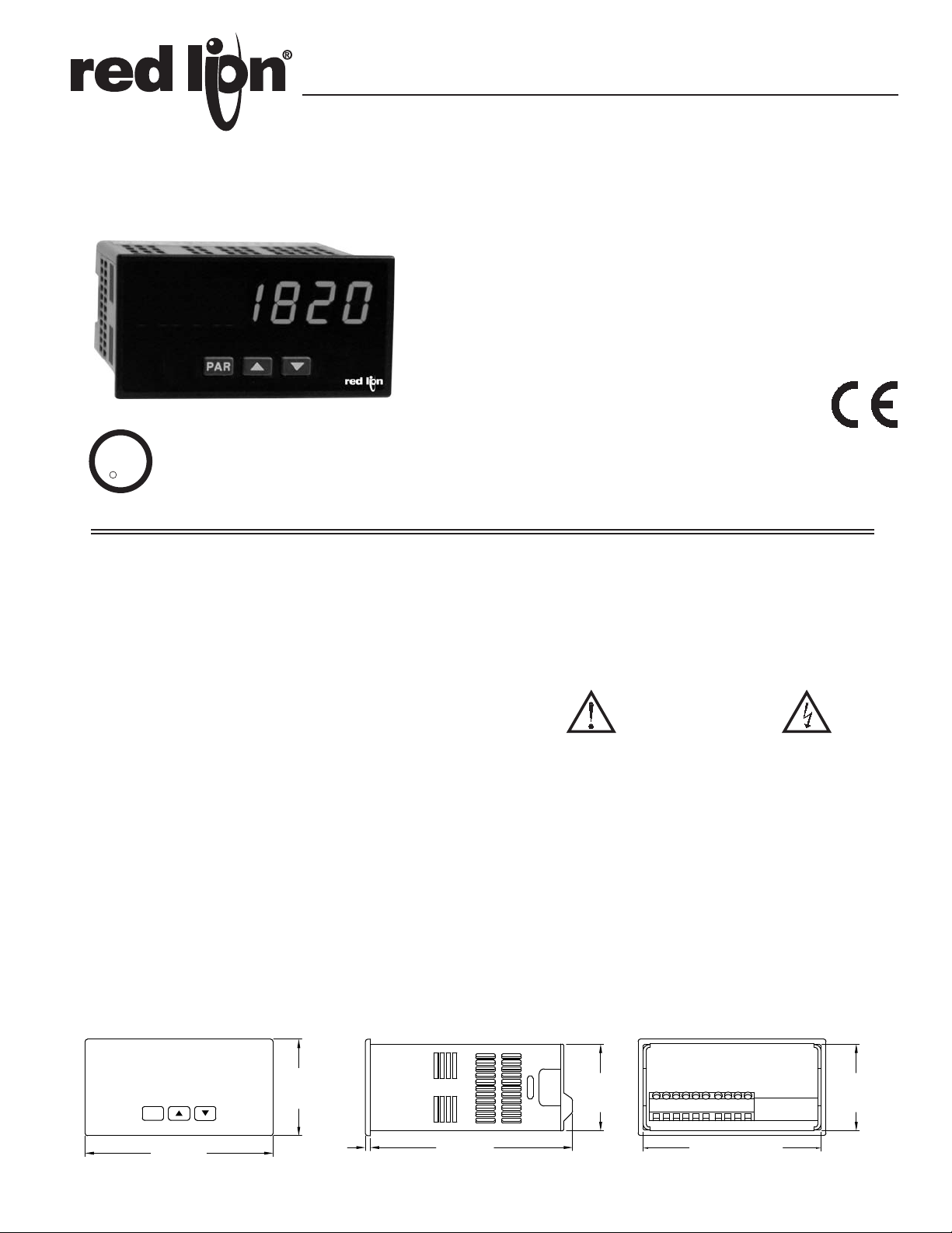
MODEL PAXLPT - PAX® LITE PROCESS TIME METER
PROCESS TIME INDICATION
6-DIGIT, 0.56" (14.2 mm) HIGH RED LED DISPLAYS
DISPLAY MODES 999999 OR 999-59
INPUT RATES UP TO 25 KHZ
ACCEPTS A WIDE VARIETY OF SENSORS
PROGRAMMABLE SCALING
PROGRAMMABLE DECIMAL POINTS
NEMA 4X/IP65 SEALED FRONT BEZEL
U
R
C
L
US LISTED
IND. CONT. EQ.
51EB
Bulletin No. PAXLPT-D
Drawing No. LP0565
Released 03/10
GENERAL DESCRIPTION
The PAX® Lite Process Time Meter, Model PAXLPT, displays a value
representing the time between a beginning and end point of a process, such as a
conveyor oven.
The PAXLPT’s display will update inversely in relation to the input signal
frequency. As input frequency increases (representing speed), the PAXLPT
time display will decrease indicating a reduction in the duration of process
time. For example, the bake time through an oven will decrease the faster the
conveyor runs.
The display can be programmed for two operating modes. Operating in the 6
digit mode, the PAXLPT can readout in any whole value, such as seconds,
minutes, or hours. This mode also provides capability for decimal points. The 5
digit mode functions as a chronometer, which has a maximum display value of
999-59. This formats the display to allow the meter to readout in hours and
minutes, minutes and seconds, etc.
The PAX Lite Process Time Indicator also has a feature called “moving
window average”. This allows one time disturbances, or irregularly spaced
items to be averaged over eight inputs, thus keeping display fluctuations to a
minimum while still updating the display on every pulse. This feature can be
enabled or disabled by a rear DIP switch.
The PAXLPT can accept many different types of sensors including magnetic
pickups, logic sensors, and NPN open collector sensors, as well as switch
contact closure sensors.
The meter has been specifically designed for harsh industrial environments.
With a NEMA 4X/IP65 sealed bezel and extensive testing to meet CE
requirements, the meter provides a tough yet reliable application solution.
DIMENSIONS In inches (mm)
Note: Recommended minimum clearance (behind the panel) for mounting clip installation is
2.1" (53.4) H x 5" (127) W.
SAFETY SUMMARY
All safety related regulations, local codes and instructions that appear in the
literature or on equipment must be observed to ensure personal safety and to
prevent damage to either the instrument or equipment connected to it. If
equipment is used in a manner not specified by the manufacturer, the protection
provided by the equipment may be impaired.
CAUTION: Risk of Danger.
Read complete instructions prior to
installation and operation of the unit.
CAUTION: Risk of electric shock.
1
Page 2
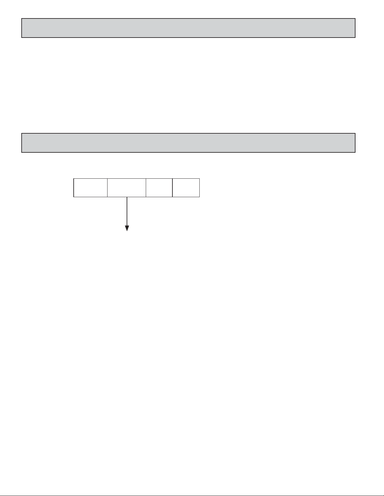
TABLE OF CONTENTS
Ordering Information . . . . . . . . . . . . . . . . . . . .2
General Meter Specifications . . . . . . . . . . . . .3
Installing the Meter . . . . . . . . . . . . . . . . . . . . . 3
Setting the Jumper and Switches . . . . . . . . . .4
ORDERING INFORMATION
Meter Part Numbers
PAXL
PT
0
Wiring the Meter . . . . . . . . . . . . . . . . . . . . . . . 4
Reviewing the Front Buttons and Display . . . .6
Scaling the Meter . . . . . . . . . . . . . . . . . . . . . .6
Programming the Meter. . . . . . . . . . . . . . . . . .7
0
PT - 6 Digit Process Time Meter
2
Page 3

GENERAL METER SPECIFICATIONS
-.00
(92 )
-.0
+.8
3.62
+.03
(45 )
1.77
-.0
+.5
-.00
+.02
PANEL
GASKET
BEZEL
PANEL
MOUNTING
SCREWS
LATCHING
SLOTS
PANEL
LATCHING
TABS
PANEL
LATCH
1. DISPLAY: 6-digit, 0.56" (14.2 mm), 7-segment red LED.
Decimal points are programmed by front panel keys (6 digit mode only)
2. POWER:
AC Power: 115/230 VAC, switch selectable. Allowable power line variation
±10%, 50/60 Hz, 6 VA.
Isolation: 2300 Vrms for 1 min. to input and DC Out/In.
DC Power: 10 to 16 VDC @ 0.1 A max.
3. SENSOR POWER: 9 to 17.5 VDC @ 100 mA max.
4. KEYPAD: 3 programming keys
5. INPUT: (DIP switch selectable)
Accepts pulses from a variety of sources including NPN-OC, PNP-OC, TTL
Outputs, Magnetic Pickups and all standard Red Lion
®
sensors.
Logic State: Active Low
Input trigger levels VIL = 1.5 V max.; VIH = 3.75 V min.
Current Sinking: Internal 7.8 K pull-up to +12 VDC, I
Current Sourcing: Internal 3.9 K pull-down, 8 mA max. @ 30 VDC max.
MAX
= 1.9 mA
MAGNETIC PICK-UP:
Sensitivity: 200 mV peak
Hysteresis: 100 mV
Input impedance: 3.9K @ 60 Hz
Maximum input voltage: ±40 V peak, 30 Vrms
6. INPUT FREQUENCY RANGE:
Max Frequency: 25 KHz
Min Frequency: 0.05 Hz
Accuracy: ±0.02%
Note: When the input pulse rate is 3 Hz or lower, the unit will utilize, if
enabled, a technique known as a “moving window average.” (This
continually averages the last eight input pulses.)
7. MEMORY: Nonvolatile E
2
PROM retains all programmable parameters.
8. ENVIRONMENTAL CONDITIONS:
Operating Temperature: 0 ° to 60 °C
Storage Temperature: -40 ° to 60 °C
Operating and Storage Humidity: 0 to 85% max. relative humidity (non-
condensing)
Vibration According to IEC 68-2-6: Operational 5 to 150 Hz, in X, Y, Z
direction for 1.5 hours, 2 g’s.
Shock According to IEC 68-2-27: Operational 30 g’s, 11 msec in 3 directions.
Altitude: Up to 2000 meters
9. CERTIFICA TIONS AND COMPLIANCES:
SAFETY
UL Recognized Component, File # E179259, UL61010A-1, CSA C22.2
No. 61010-1
Recognized to U.S. and Canadian requirements under the Component
Recognition Program of Underwriters Laboratories, Inc.
UL Listed, File # E137808, UL508, CSA C22.2 No. 14-M95
LISTED by Und. Lab. Inc. to U.S. and Canadian safety standards
Type 4X Enclosure rating (Face only), UL50
IECEE CB Scheme Test Report # 04ME11209-20041018
Issued by Underwriters Laboratories, Inc.
IEC 61010-1, EN 61010-1: Safety requirements for electrical equipment
for measurement, control, and laboratory use, Part 1.
IP65 Enclosure rating (Face only), IEC 529
IP20 Enclosure rating (Rear of unit), IEC 529
ELECTROMAGNETIC COMPATIBILITY
Emissions and Immunity to EN 61326: Electrical Equipment for Measurement,
Control and Laboratory use.
Immunity to Industrial Locations:
Criterion AEN 61000-4-2Electrostatic discharge
4 kV contact discharge
8 kV air discharge
Criterion AEN 61000-4-3Electromagnetic RF fields
10 V/m
EN 61000-4-4Fast transients (burst)
Criterion A
2
2 kV power
2 kV signal
EN 61000-4-5Surge
Criterion A
2
1 kV L-L,
2 kV L&N-E power
1 kV signal
Criterion AEN 61000-4-6RF conducted interference
3 V/rms
Criterion AEN 61000-4-8Power frequency magnetic fields
30 A/m
Criterion AEN 61000-4-11Voltage dip/interruptions
0.5 cycle
Emissions:
Class BEN 55011Emissions
Notes:
1. Criterion A: Normal operation within specified limits.
2. EMI filter placed on the DC power supply, when DC powered: Corcom
#1VB3 or Schaffner #FN610-1/07 (RLC #LFIL0000).
10. CONNECTIONS: High compression cage-clamp terminal block
Wire Strip Length: 0.3" (7.5 mm)
Wire Gage Capacity: 30-14 AWG copper wire.
Torque: 4.5 inch-lbs (0.51 N-m) max.
11. CONSTRUCTION: This unit is rated for NEMA 4X/IP65 outdoor use.
IP20 Touch safe. Installation Category II, Pollution Degree 2. One piece
bezel/case. Flame resistant. Synthetic rubber keypad. Panel gasket and
mounting clip included.
12. WEIGHT: 12 oz (340 g)
1.0 INSTALLING THE METER
Installation
The PAX Lite meets NEMA 4X/IP65 requirements when properly installed.
The unit is intended to be mounted into an enclosed panel. Prepare the panel
cutout to the dimensions shown. Remove the panel latch from the unit. Slide the
panel gasket over the rear of the unit to the back of the bezel. The unit should
be installed fully assembled. Insert the unit into the panel cutout.
While holding the unit in place, push
the panel latch over the rear of the
unit so that the tabs of the panel
latch engage in the slots on
the case. The panel latch
should be engaged
in the farthest
forward slot possible. To achieve a proper seal, tighten the latch screws evenly
until the unit is snug in the panel (Torque to approximately 7 in-lbs [79N-cm]).
Do not over-tighten the screws.
Installation Environment
The unit should be installed in a location that does not exceed the maximum
operating temperature and provides good air circulation. Placing the unit near
devices that generate excessive heat should be avoided.
The bezel should be cleaned only with a soft cloth and neutral soap product.
Do NOT use solvents. Continuous exposure to direct sunlight may accelerate the
aging process of the bezel.
Do not use tools of any kind (screwdrivers, pens, pencils, etc.) to operate the
keypad of the unit.
PANEL CUT-OUT
3
Page 4

2.0 SETTING THE JUMPER AND SWITCHES
3
1
2
5
4
ON
6
6
5
4
3
2
1
ON
DIS PGM
DIS AVE
MAG
LO Freq.
SRC.
SNK.
EN PGM
EN AVE
LOGIC
HI Freq.
Not Active
Not Active
The meter has a jumper and switches, which must be checked and/or changed
prior to applying power. To access the power switch and the jumper, remove the
meter base from the case by firmly squeezing and pulling back on the side rear
finger tabs. This should lower the latch below the case slot (which is located just
in front of the finger tabs). It is recommended to release the latch on one side,
then start the other side latch.
Power Selection Switch
Caution: Insure the AC power selection switch is set for the
proper voltage before powering-up the meter. The meter is shipped
from the factory in the 230 VAC position.
Mode Selection Jumper
Inside the meter is also the Mode Selection Jumper, located near the display
board. This jumper will select operation in the 6 digit mode or 5 digit
(chronometer) mode. When the jumper is positioned toward the display board,
the unit will be in the 6 digit mode of operation. With the jumper positioned
away from the display board, the meter is in the 5 digit (chronometer) mode.
This unit ships from the factory in the 6 digit mode.
Set-Up DIP Switches
A DIP switch is located at the rear of the meter,
and is fully accessible when the unit is in the case.
It is used for the selection of the input parameters
and program disable. For the correct input setup,
refer to 3.2 Input Wiring.
SWITCH 1
SNK.: Adds internal 7.8 K pull-up resistor to + 12 VDC, I
SWITCH 2
SRC.: Adds internal 3.9 K pull-down resistor, 8 mA max. @ 30 VDC max.
SWITCH 3
HI Frequency: Removes damping capacitor and allows max. frequency.
LO Frequency: Limits input frequency to 50 Hz and input pulse widths
to 10 msec.
SWITCH 4
LOGIC: Input trigger levels V
MAG: 200 mV peak input (must have SRC on)
= 1.5 V max.; VIH = 3.75 V max.
IL
SWITCH 5
Enable Programming: Enables programming through the front panel buttons
Disables Programming: Disables the front panel buttons from any
programming changes
SWITCH 6
Enable Averaging: Enables moving windows averaging feature.
Disable Averaging: Disables moving windows averaging feature.
FRONT DISPLAY
MODE SELECTION JUMPER
POWER
SELECTION
SWITCH
230
115
MAX
= 1.9 mA
3.0 WIRING THE METER
WIRING OVERVIEW
Electrical connections are made via screw-clamp terminals located on the
back of the meter. All conductors should conform to the meter’s voltage and
current ratings. All cabling should conform to appropriate standards of good
installation, local codes and regulations. It is recommended that the power
supplied to the meter (DC or AC) be protected by a fuse or circuit breaker.
When wiring the meter, compare the numbers embossed on the back of the
meter case against those shown in wiring drawings for proper wire position. Strip
the wire, leaving approximately 0.3" (7.5 mm) bare lead exposed (stranded wires
should be tinned with solder.) Insert the lead under the correct screw-clamp
terminal and tighten until the wire is secure. (Pull wire to verify tightness.)
EMC INSTALLATION GUIDELINES
Although this meter is designed with a high degree of immunity to ElectroMagnetic Interference (EMI), proper installation and wiring methods must be
followed to ensure compatibility in each application. The type of the electrical
noise, source or coupling method into the meter may be different for various
installations. The meter becomes more immune to EMI with fewer I/O
connections. Cable length, routing, and shield termination are very important
and can mean the difference between a successful or troublesome installation.
Listed below are some EMC guidelines for successful installation in an
industrial environment.
1. The meter should be mounted in a metal enclosure, which is properly
connected to protective earth.
2. Use shielded (screened) cables for all Signal and Control inputs. The shield
(screen) pigtail connection should be made as short as possible. The
connection point for the shield depends somewhat upon the application.
Listed below are the recommended methods of connecting the shield, in order
of their effectiveness.
a. Connect the shield only at the panel where the unit is mounted to earth
ground (protective earth).
b. Connect the shield to earth ground at both ends of the cable, usually when
the noise source frequency is above 1 MHz.
REAR TERMINALS
INPUT SET-UP
DIP SWITCHES
c. Connect the shield to common of the meter and leave the other end of the
shield unconnected and insulated from earth ground.
3. Never run Signal or Control cables in the same conduit or raceway with AC
power lines, conductors feeding motors, solenoids, SCR controls, and
heaters, etc. The cables should be run in metal conduit that is properly
grounded. This is especially useful in applications where cable runs are long
and portable two-way radios are used in close proximity or if the installation
is near a commercial radio transmitter.
4. Signal or Control cables within an enclosure should be routed as far as possible
from contactors, control relays, transformers, and other noisy components.
5. In extremely high EMI environments, the use of external EMI suppression
devices, such as ferrite suppression cores, is effective. Install them on Signal
and Control cables as close to the unit as possible. Loop the cable through the
core several times or use multiple cores on each cable for additional protection.
Install line filters on the power input cable to the unit to suppress power line
interference. Install them near the power entry point of the enclosure. The
following EMI suppression devices (or equivalent) are recommended:
Ferrite Suppression Cores for signal and control cables:
Fair-Rite # 0443167251 (RLC# FCOR0000)
TDK # ZCAT3035-1330A
Steward # 28B2029-0A0
Line Filters for input power cables:
Schaffner # FN610-1/07 (RLC# LFIL0000)
Schaffner # FN670-1.8/07
Corcom # 1 VR3
Note: Reference manufacturer’s instructions when installing a line filter.
6. Long cable runs are more susceptible to EMI pickup than short cable runs.
Therefore, keep cable runs as short as possible.
7. Switching of inductive loads produces high EMI. Use of snubbers across
inductive loads suppresses EMI.
Snubber: RLC# SNUB0000.
4
Page 5

MAGNETIC PICKUP
DC OUT/IN
3
COMM
4
INPUT
5
2
1
ON
43
*
3.1 POWER WIRING
3 4
DC OUT/IN
COMM
+
-
AC Power
Terminal 1: VAC
Terminal 2: VAC
AC
AC
1 2
3.2 INPUT WIRING
Magnetic Pickup
Current Sinking Output
DC Power
Terminal 3: +VDC
Terminal 4: COMM
AC Inputs From Tach Generators, Etc.
Current Sourcing Output
DC OUT/IN
4
INPUT
COMM
53
Resistor to limit current
to 2.5 mA MAX.
Two Wire Proximity, Current Source
INPUT
ON
*
1
43
2
ON
*
1
4
3
2
AC
DC OUT/IN
43 5
COMM
2.2KΩ
Interfacing With TTL
ON
1
*
3
2
NPN O.C.
4
DC OUT/IN
COMM
3 4 5
INPUT
Emitter Follower; Current Source
ON
DC OUT/IN
COMM
3 4 5
INPUT
*
1
3 4
2
*Switch position is application dependent.
COMM
DC OUT/IN
3 4 5
INPUT
ON
1
*
3
2
PNP O.C.
ON
*
COMM
43 5
INPUT
DIODE
1
3
4
2
+5V
COMM
DC OUT/IN
4
5
Page 6

4.0 REVIEWING THE FRONT BUTTONS AND DISPLAY
PAR
KEY DISPLAY MODE OPERATION PROGRAMMING MODE OPERATION
PAR Access Programming Mode Store selected parameter and index to next parameter
No Function Increment selected digit of parameter value
No Function Select digit position in parameter value
5.0 SCALING THE METER
In many industrial applications, a meter is required to display the process
time of an operation or event. The pulses from a sensor are received by the
P AXLPT, and then scaled to produce just such a readout. The following formula
will help provide the scaling values to achieve the desired readout.
SF = DR x PPS
WHERE:
SF = Scale Factor
DR = Desired Readout*
PPS = Pulses per Second
To calculate the PPS multiply the RPM (Revolutions per Minute) by the PPR
(Pulses per Revolution) and divide by 60.
RPM x PPR
60
*For applications requiring a decimal point, select and program the
appropriate decimal point. When calculating the Scale Factor, use the whole
value of the number to be displayed, for example, 50.0 minutes, the Desired
Readout in this case is 500. Do not use decimal points in the Desired Readout
when calculating the scale factor.
For calculated SF values less than 59,999
If the Scale Factor is a value less than 59,999, it can be entered directly
into the meter as the Scale Factor and the Scale Multiplier can be left at 1.
For calculated SF values greater than 59,999
If the Scale Factor is a value over 59,999 (maximum value), the Scale
Multiplier must be used to reduce the calculated Scale Factor value until it is
less than 59,999. The Scale Multiplier divides the calculated Scale Factor
value by 1, 10, 100 and 1000, thus reducing the calculated value accordingly.
Select the appropriate Scale Multiplier value that allows the Scale Factor to
be a value under 59,999. Both the Scale Factor and Scale Multiplier can then
be entered into the meter.
Example 1 (6 Digit):
DR = 150 minutes
PPS = 450 RPM x 60 PPR
60
PPS = 450
SF = DR x PPS
SF = 150 x 450
SF = 67,500
Since the SF value is greater than 59,999, the SM will be needed to reduce
the calculated value to value less than 59,999. Using the SM of 10, the 67,500
value is divide by 10, reducing the SF to a value of 6750. The meter can be
programmed for a SF of 6750 and a SM of 10.
Example 2 (5 Digit):
DR = 2 hours and 23 minutes (2-23)
PPS = 138 RPM x 100 PPR
60
PPS = 230
To calculate the Scale Factor for a 5 Digit application, first convert the DR
to its base units.
DR = 2 (hours) x 60 + 23
DR = 120 + 23
DR = 143 minutes
SF = DR x PPS
SF = 143 x 230
SF = 32,890
Since the SF value is less than 59,999, it can be entered directly as the SF
and the SM will be 1. Note: When programmed for the 5 Digit mode, the
meter will convert the D.R. back to the hours and minutes format.
6
Page 7

6.0 PROGRAMMING THE METER
Decimal
Position
PAR
Scale
Factor
PAR
Scale
Multiplier
PAR
TIME
DISPLAY
PAR
TIME
DISPLAY
PROGRAMMING SEQUENCE
The Process Time Indicator has three programmable parameters which are
entered in the sequence shown above, using the front panel push buttons.
Before programming, please refer to the section on Scaling the Meter to
determine the Decimal Position, Scale Factor and Scale Multiplier to use for the
specific application.
Note: Programming mode can be locked out with the Program Disable DIP
switch. With the switch in the Disabled (up) position the meter will not enter
programming mode. Refer to the section on DIP switch setup.
PROGRAMMING MODE ENTRY
Press the PAR key to enter Programming Mode. The meter briefly displays
followed by the first programming parameter described below.
PROGRAMMING PARAMETERS
In programming mode, the display alternates between the parameter and the
current selection or value for that parameter. The dual display with arrows is
used below to illustrate the alternating display. The selection choices or value
range for each parameter is shown to the right of the alternating display.
DECIMAL POSITION (6-digit version only)
display. The selection is used when calculating the Scale Factor. This parameter
only appears when the meter is configured for the conventional (6-digit) display.
Press the arrow keys ( or ) to sequence through the selection list until the
desired selection is shown. Press the PAR key to save the displayed selection
and advance to the next parameter.
This parameter selects the decimal point position on the
SCALE FACTOR
to
SCALE MULTIPLIER
The Scale Multiplier is used in combination with the Scale Factor to obtain
the desired process time readout. (See details on Scaling the Meter.)
Press the arrow keys ( or ) to sequence through the selection list until the
desired selection is displayed. Press the PAR key to save the selection and exit
programming mode.
PROGRAMMING MODE EXIT
The meter exits Programming Mode when the PAR key is pressed to save the
Scale Multiplier selection. The meter briefly displays upon exiting
Programming Mode. All programmed selections are now transferred to the nonvolatile memory and the meter returns to the Process Time display.
(If power loss occurs during programming mode, verify parameter changes
and reprogram, if necessary, when power is restored.)
PROGRAMMING MODE TIME OUT
The Programming Mode has an automatic time out feature. If no keypad
activity is detected for approximately 60 seconds, the meter automatically exits
Programming Mode. The meter briefly displays and returns to the Process
Time display. When automatic timeout occurs, any changes that were made to
the parameter currently being programmed, will not be saved.
FACTORY SETTINGS
The factory settings for the programming parameters are shown above in the
alternating display illustrations. The factory settings can be easily restored by
removing power from the meter, and then pressing and holding the PAR key
while power is reapplied. The meter displays until the PAR key is
released. The normal power-up sequence then resumes, with the factory settings
loaded and saved in non-volatile memory.
Note: The Program Disable DIP switch must be in the Enabled (down)
position to allow loading factory settings. See section on DIP switch setup.
The Scale Factor is used in combination with the Scale Multiplier to obtain
the desired process time readout. (See details on Scaling the Meter.)
The Scale Factor is displayed as a five-digit value with one selected digit
flashing (initially digit 5). Press the (up arrow) key to increment the value of
the selected (flashing) digit. Holding the key automatically scrolls the value
of the selected digit.
Press the (down arrow) key to select the next digit position to the right.
Use the key to increment the value of this digit to the desired number. Press
the key again to select the next digit to be changed. Repeat the “select and
set” sequence until all digits are displaying the desired Scale Factor value. Press
the PAR key to save the displayed value and advance to the next parameter.
Holding the key automatically scrolls through each digit position.
7
Page 8

The Company warrants the products it manufactures against defects in materials and workmanship
LIMITED WARRANTY
for a period limited to two years from the date of shipment, provided the products have been stored,
handled, installed, and used under proper conditions. The Company’s liability under this limited
warranty shall extend only to the repair or replacement of a defective product, at The Company’s
option. The Company disclaims all liability for any affirmation, promise or representation with
respect to the products.
The customer agrees to hold Red Lion Controls harmless from, defend, and indemnify RLC against
damages, claims, and expenses arising out of subsequent sales of RLC products or products
containing components manufactured by RLC and based upon personal injuries, deaths, property
damage, lost profits, and other matters which Buyer, its employees, or sub-contractors are or may be
to any extent liable, including without limitation penalties imposed by the Consumer Product Safety
Act (P.L. 92-573) and liability imposed upon any person pursuant to the Magnuson-Moss Warranty
Act (P.L. 93-637), as now in effect or as amended hereafter.
No warranties expressed or implied are created with respect to The Company’s products except those
expressly contained herein. The Customer acknowledges the disclaimers and limitations contained
herein and relies on no other warranties or affirmations.
Red Lion Controls
Headquarters
20 Willow Springs Circle
York PA 17406
Tel +1 (717) 767-6511
Fax +1 (717) 764-0839
Red Lion Controls
Europe
Printerweg 10
NL - 3821 AD Amersfoort
Tel +31 (0) 334 723 225
Fax +31 (0) 334 893 793
Red Lion Controls
India
54, Vishvas Tenement
GST Road, New Ranip,
Ahmedabad-382480 Gujarat, India
Tel +91 987 954 0503
Fax +91 79 275 31 350
Red Lion Controls
China
Unit 101, XinAn Plaza
Building 13, No.99 Tianzhou Road
ShangHai, P.R. China 200223
Tel +86 21 6113-3688
Fax +86 21 6113-3683
 Loading...