

Page 1
1
2
3
4
5
6
7
8
9
10
11
3.60 (91.4)
(44.5)
1.75
(96.5)
3.80
1.95
(49.5)
(2.5)
0.10
(104.1)
4.10
(44.5)
1.75
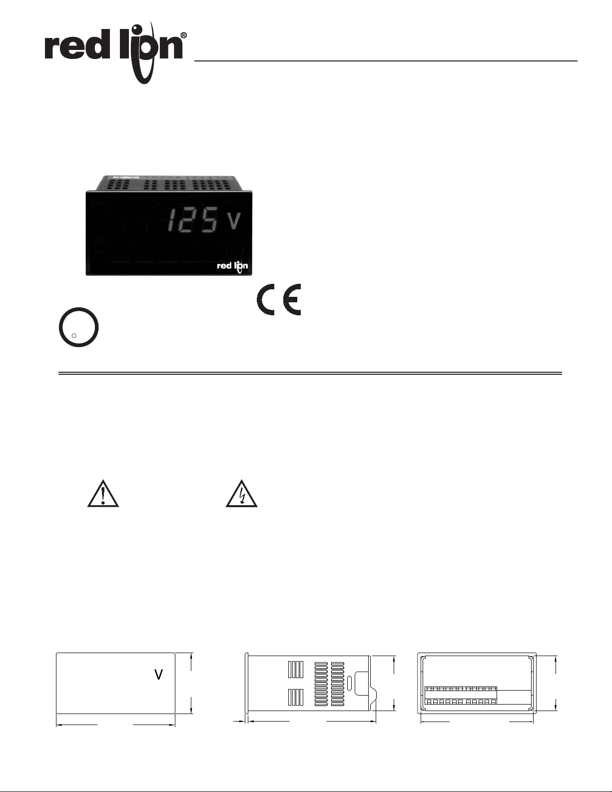
MODEL PAXLHV - PAX LITE AC VOLTAGE MONITOR
C
US LISTED
3-DIGIT, 0.56" (14.2 mm) HIGH RED LED DISPLAY
AUTO ZEROING CIRCUIT
NEMA 4X/IP65 SEALED FRONT BEZEL
OPTIONAL CUSTOM UNITS OVERLAY W/BACKLIGHT
UP TO 600 VAC MAX
U
R
C
US LISTED
L
IND. CONT. EQ.
51EB
GENERAL DESCRIPTION
The Model PAXLHV is designed for AC voltage monitoring. The half-wave
rectified input signal is calibrated to indicate the RMS value of a pure
sinusoidal wave-form. The front bezel meets NEMA 4X/IP65 requirements
when properly installed.
CAUTION: Read complete
instructions prior to installation
and operation of the unit.
DIMENSIONS In inches (mm)
CAUTION: Risk of electric shock.
Note: Recommended minimum clearance (behind the panel) for mounting clip installation is
2.1" (53.4) H x 5.0" (127) W.
SAFETY SUMMARY
All safety related regulations, local codes and instructions that appear in the
literature or on equipment must be observed to ensure personal safety and to
prevent damage to either the instrument or equipment connected to it. If
equipment is used in a manner not specified by the manufacturer, the protection
provided by the equipment may be impaired.
DEFINITION OF TERMS
INSTALLATION CATEGORY (overvoltage category) I:
Signal level, special equipment or parts of equipment, telecommunication,
electronic, etc. with smaller transient overvoltages than Installation
Category (overvoltage category) II.
INSTALLATION CATEGORY (overvoltage category) II:
Local level, appliances, portable equipment, etc. with smaller transient
overvoltages than Installation Category (overvoltage category) III.
1
Page 2
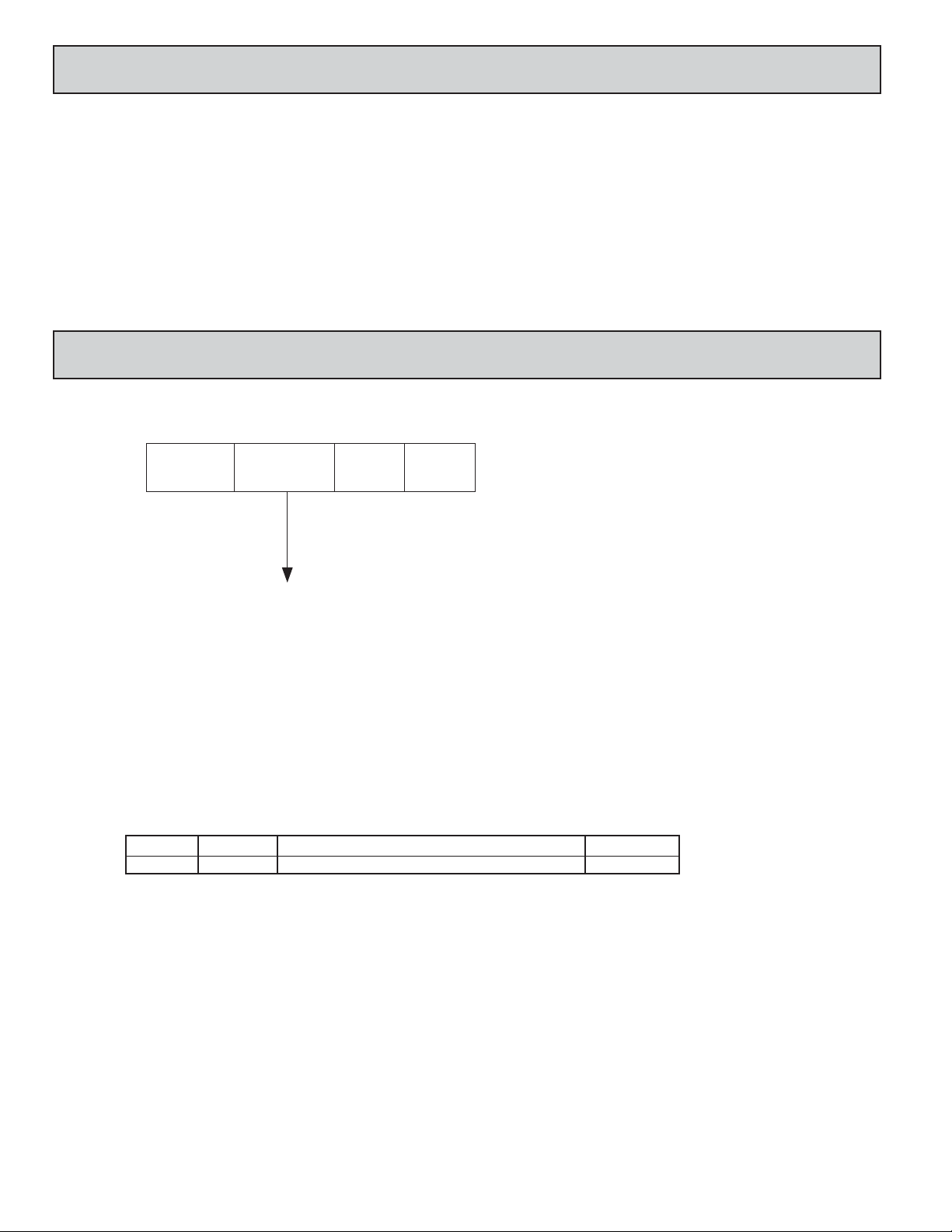
TABLE OF CONTENTS
Ordering Information . . . . . . . . . . . . . . . . . . . .2
General Meter Specifications . . . . . . . . . . . . .3
Accessories . . . . . . . . . . . . . . . . . . . . . . . . . . .3
ORDERING INFORMATION
Meter Part Numbers
PAXL
HV 0
0
Installing the Meter . . . . . . . . . . . . . . . . . . . . . 4
Setting the Switches . . . . . . . . . . . . . . . . . . . . 4
Wiring the Meter . . . . . . . . . . . . . . . . . . . . . . . 5
HV - AC Voltage Input
Accessories Part Number
TYPE PART NUMBERSDESCRIPTIONMODEL NO.
PAXLBK30Units Label Kit Accessory PAXLBKAccessories
2
Page 3

GENERAL METER SPECIFICATIONS
1. DISPLAY: 3-digit, 0.56" (14.2 mm) high character, 7-segment Red LED
2. POWER: 115 or 230 VAC, switch selectable. Allowable power line variation
±10%, 50/60 Hz, 6 VA. Installation Category II, Pollution Degree 2.
Isolation: 2300 Vrms for 1 min. to input
Working Voltage: 300 V max., CAT II
3. ACCURACY: At 23°C, 85% R.H.; ±(0.1% of Reading + 2 digits)
4. INPUT IMPEDANCE: 1 M
5. INPUT RANGE: 0 to 600 VAC max. @ 45 to 500 Hz. Installation Category I
6. RESOLUTION: 1 VAC
7. ENVIRONMENTAL CONDITIONS:
Operating Temperature Range: 0° to 60°C
Storage Temperature Range: -40° to 80°C
Operating and Storage Humidity: 85% max. relative humidity (non-
condensing)
Temperature Coefficient: ±150 PPM/°C
Vibration According to IEC 68-2-6: Operational 5 to 150 Hz, in X, Y, Z
direction for 1.5 hours, 2 g’s.
Shock According to IEC 68-2-27: Operational 30 g’ s, 11 msec in 3 directions.
Altitude: Up to 2000 meters
8. READING RATE: 400 msec., nominal
9. RESPONSE TIME: 1 sec. nominal for a step change input.
10. CERTIFICA TIONS AND COMPLIANCES:
SAFETY
UL Recognized Component, File #E179259, UL61010A-1, CSA C22.2 No. 61010-1
Recognized to U.S. and Canadian requirements under the Component
Recognition Program of Underwriters Laboratories Inc.
UL Listed, File #E137808, UL508, CSA C22.2 No. 14-M95
LISTED by Und. Lab. Inc. to U.S. and Canadian safety standards
Type 4X Enclosure rating (Face only), UL50
IECEE CB Scheme Test Report #04ME11209-20041018
Issued by Underwriters Laboratories, Inc.
IEC 61010-1, EN 61010-1: Safety requirements for electrical equipment
for measurement, control, and laboratory use, Part 1.
IP65 Enclosure rating (Face only), IEC 529
ELECTROMAGNETIC COMPATIBILITY:
Emissions and Immunity to EN 61326: Electrical Equipment for
Measurement, Control and Laboratory use.
Immunity to Industrial Locations:
Criterion AEN 61000-4-2Electrostatic discharge
4 kV contact discharge
8 kV air discharge
Criterion B EN 61000-4-3Electromagnetic RF fields
10 V/m
Criterion AEN 61000-4-4Fast transients (burst)
2 kV power
2 kV signal
Criterion AEN 61000-4-5Surge
1 kV L-L,
2 kV L&N-E power
Criterion AEN 61000-4-6RF conducted interference
3 V/rms
Criterion AEN 61000-4-11Voltage dip/interruptions
0.5 cycle; 40 % variation
Emissions:
Class BEN 55011Emissions
Notes:
1. Criterion A: Normal operation within specified limits.
2. Criterion B: Temporary loss of performance from which the unit selfrecovers.
11. CONNECTIONS: High compression cage-clamp terminal block
Wire Strip Length: 0.3" (7.5 mm)
Wire Gage: 30-14 AWG copper wire
Torque: 4.5 inch-lbs (0.51 N-m) max.
12. CONSTRUCTION: This unit is rated for NEMA 4X/IP65 outdoor use.
Installation Category II, Pollution Degree 2. One piece bezel/case. Flame
resistant. Panel Gasket and mounting clip included.
13. WEIGHT: 0.65 lbs. (0.24 Kg)
ACCESSORIES
UNITS LABEL KIT (PAXLBK)
Each meter has a units indicator with backlighting that can be customized
using the Units Label Kit. The backlight is controlled by a DIP switch.
3
Page 4

1.0 INSTALLING THE METER
-.00
(92 )
-.0
+.8
3.62
+.03
(45 )
1.77
-.0
+.5
-.00
+.02
LATCHING
TAB S
PAN EL
LATCH
PAN EL
MOUNTING
SCREWS
LATCHING
SLOTS
PAN EL
GASKET
BEZEL
PAN EL
3
4
1
2
ON
Installation
The PAX meets NEMA 4X/IP65 requirements when properly installed. The
unit is intended to be mounted into an enclosed panel. Prepare the panel cutout
to the dimensions shown. Remove the panel latch from the unit. Slide the panel
gasket over the rear of the unit to the back
of the bezel. The unit should be installed
fully assembled. Insert the unit
into the panel cutout.
While holding the unit in place, push the panel latch over the rear of the unit
so that the tabs of the panel latch engage in the slots on the case. The panel latch
should be engaged in the farthest forward slot possible. T o achieve a proper seal,
tighten the latch screws evenly until the unit is snug in the panel (Torque to
approximately 7 in-lbs [79N-cm]). Do not over-tighten the screws.
Installation Environment
The unit should be installed in a location that does not exceed the maximum
operating temperature and provides good air circulation. Placing the unit near
devices that generate excessive heat should be avoided.
The bezel should be cleaned only with a soft cloth and neutral soap product.
Do NOT use solvents. Continuous exposure to direct sunlight may accelerate the
aging process of the bezel.
PANEL CUT-OUT
2.0 SETTING THE SWITCHES
The meter has a switch, which must be checked and/or changed prior to
applying power. To access the switch, remove the meter base from the case by
firmly squeezing and pulling back on the side rear finger tabs. This should lower
the latch below the case slot (which is located just in front of the finger tabs). It
is recommended to release the latch on one side, then start the other side latch.
Power Selection Switch
Caution: Insure the AC power selection switch is set for the
proper voltage before powering-up the meter. The meter is shipped
from the factory in the 230 VAC position.
Set-Up DIP Switches
A DIP switch is located inside the meter. It is used for the selection of decimal
points and backlight annunciator. Selecting the “ON” position enables the
function.
FUNCTIONSWITCH
Decimal Point 1 (000.0)1
Decimal Point 2 (00.00)2
Decimal Point 3 (0.000)3
Backlight Annunciator for Units Label4
4
Page 5

3.0 WIRING THE METER
1
2
8
5
POWER
SUPPLY
WAVE
SHAPING
CIRCUIT
PROCESS
CIRCUITRY
CALIBRATION
ADJUSTMENT
+V
1M
DISPLAY
INPUT
POWER
COMMON
(NEUTRAL)
600VAC
(HOT)
1 2
AC
AC
5 8
V
600V MAX. AC
COMMON
600 VAC
Neutral
WIRING OVERVIEW
All conductors should meet voltage and current ratings for each terminal. Also,
cabling should conform to appropriate standards of good installation, local codes
and regulations. It is recommended that power supplied to the unit be protected
by a fuse or circuit breaker. As depicted in the drawing of the Model PAXLHV,
all connections are made on the terminal block located at the rear of the unit.
EMC INSTALLATION GUIDELINES
Although this meter is designed with a high degree of immunity to
Electromagnetic Interference (EMI), proper installation and wiring methods
must be followed to ensure compatibility in each application. The type of the
electrical noise, source or coupling method into the meter may be different for
various installations. Cable length, routing and shield termination are very
important and can mean the difference between a successful or a troublesome
installation. Listed below are some EMC guidelines for successful installation
in an industrial environment.
1. The meter should be mounted in a metal enclosure, that is properly connected
to protective earth.
2. Use shielded (screened) cables for all Signal and Control inputs. The shield
(screen) pigtail connection should be made as short as possible. The
connection point for the shield depends somewhat upon the application.
Listed below are the recommended methods of connecting the shield, in order
of their effectiveness.
a. Connect the shield only at the panel where the meter is mounted to earth
ground (protective earth).
b. Connect the shield to earth ground at both ends of the cable, usually when
the noise source frequency is above 1 MHz.
c. Connect the shield to common of the meter and leave the other end of the
shield unconnected and insulated from earth ground.
3. Never run Signal or Control cables in the same conduit or raceway with AC
power lines, conductors feeding motors, solenoids, SCR controls, and
heaters, etc. The cables should be run in metal conduit that is properly
grounded. This is especially useful in applications where cable runs are long
and portable two-way radios are used in close proximity or if the installation
is near a commercial radio transmitter.
BLOCK DIAGRAM
The PAX Lite AC Voltage Monitor incorporates a built-in precision
voltage divider that provides direct measurement from 0 to 600 VAC.
4. Signal or Control cables within an enclosure should be routed as far as possible
from contactors, control relays, transformers, and other noisy components.
5. In extremely high EMI environments, the use of external EMI suppression
devices, such as ferrite suppression cores, is effective. Install them on Signal
and Control cables as close to the unit as possible. Loop the cable through the
core several times or use multiple cores on each cable for additional protection.
Install line filters on the power input cable to the unit to suppress power line
interference. Install them near the power entry point of the enclosure. The
following EMI suppression devices (or equivalent) are recommended:
Ferrite Suppression Cores for signal and control cables:
Fair-Rite # 0443167251 (RLC #FCOR0000)
TDK # ZCAT3035-1330A
Steward #28B2029-0A0
Line Filters for input power cables:
Schaffner # FN610-1/07 (RLC #LFIL0000)
Schaffner # FN670-1.8/07
Corcom #1VB3
Corcom #1VR3
Note: Reference manufacturer's instructions when installing a line filter.
6. Long cable runs are more susceptible to EMI pickup than short cable runs.
Therefore, keep cable runs as short as possible.
3.1 POWER WIRING
Primary AC power is connected to terminal 1 and 2 (Marked AC Power,
located on the left-hand side of the terminal block). For best results, the AC
power should be relatively “Clean” and within the specified ±10% variation
limit. Drawing power from heavily loaded circuits or from circuits that also
power loads that cycle on and off, should be avoided.
AC Power
Terminal 1: VAC
Terminal 2: VAC
115/230
3.2 INPUT SIGNAL WIRING
Input connections are made on terminal 5 and 8. When powering the
PAXLHV with the same voltage that is being measured, terminal 5 (COMM.)
should be connected to neutral for the most stable reading on the display. If an
unstable display results from measuring a voltage that is isolated from the supply
voltage, reversing the supply voltage connections may correct this condition.
Voltage Input
Terminal 5: Common
Terminal 8: 600 VAC
5
 Loading...