

Page 1
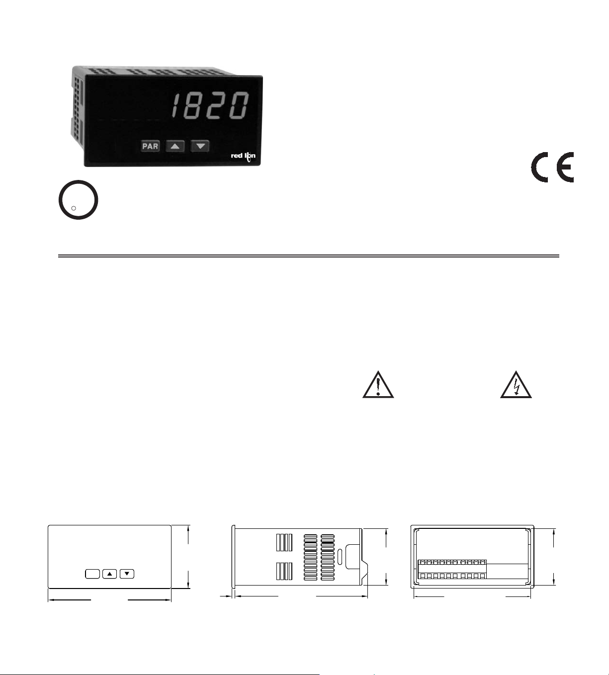
MODEL PAXLC - PAX® LITE COUNTER
3.60 (91.4)
(44.5)
1.75
(96.5)
3.80
1.95
(49.5)
(2.5)
.10
(104.1)
4.10
(44.5)
1.75
PAR
9
1
3
2
4
5
6
7
8
10
C
US LISTED
AVAILABLE IN 6 OR 8-DIGIT VERSIONS
6-DIGIT, 0.56" (14.2 mm) / 8-DIGIT, 0.4" (10.1 mm) HIGH RED LED
DISPLAYS
ACCEPTS INPUT COUNT RATES UP TO 25 KHZ
BI-DIRECTIONAL COUNTING
REMOTE RESET CAPABILTY
DISPLAY STORE
COUNT INHIBIT
PROGRAMMABLE SCALE FACTOR
NEMA 4X/IP65 SEALED FRONT BEZEL
U
R
C
L
US LISTED
IND. CONT. EQ.
51EB
GENERAL DESCRIPTION
The PAX® Lite Counter, Model PAXLC, is a versatile totalizing counter that
can be adapted to a wide variety of counting, measuring, and positioning
readout applications.
The unit features a programmable scale factor, front panel and remote reset,
store, inhibit, and a count rate of 25 KHz, while offering an economical solution
to any totalizing need.
The PAXLC accepts digital inputs from a variety of sources including switch
contacts, NPN-OC and TTL outputs, as well as most standard Red Lion sensors.
The input can be scaled to display any desired unit of measure by simply using
the programmable scale factor. The meter can accept bi-directional and unidirectional signals.
The meter is programmed through the front panel buttons and the use of DIP
switches. The Down Arrow Key will also function as a front panel display reset.
Once the front panel programming is complete, the buttons can be disabled by
a DIP switch setting.
The meter has been specifically designed for harsh industrial environments.
With a NEMA 4X/IP65 sealed bezel and extensive testing to meet CE
requirements, the meter provides a tough yet reliable application solution.
DIMENSIONS In inches (mm)
Note: Recommended minimum clearance (behind the panel) for mounting clip installation is
2.1" (53.4) H x 5" (127) W.
SAFETY SUMMARY
All safety related regulations, local codes and instructions that appear in the
literature or on equipment must be observed to ensure personal safety and to
prevent damage to either the instrument or equipment connected to it. If
equipment is used in a manner not specified by the manufacturer, the protection
provided by the equipment may be impaired.
CAUTION: Risk of Danger.
Read complete instructions prior to
installation and operation of the unit.
CAUTION: Risk of electric shock.
1
Page 2
TABLE OF CONTENTS
Ordering Information . . . . . . . . . . . . . . . . . . . .2
General Meter Specifications . . . . . . . . . . . . .3
Installing the Meter . . . . . . . . . . . . . . . . . . . . . 3
Setting the Switches . . . . . . . . . . . . . . . . . . . . 4
ORDERING INFORMATION
Meter Part Numbers
PAXL
0
Wiring the Meter . . . . . . . . . . . . . . . . . . . . . . . 4
Reviewing the Front Buttons and Display . . . .6
Scaling the Meter . . . . . . . . . . . . . . . . . . . . . .6
Programming the Meter. . . . . . . . . . . . . . . . . .7
0
C6 - 6 Digit Counter
C8 - 8 Digit Counter
2
Page 3
GENERAL METER SPECIFICATIONS
-.00
(92 )
-.0
+.8
3.62
+.03
(45 )
1.77
-.0
+.5
-.00
+.02
LATCHING
TABS
PANE L
LATCH
PANE L
MOUNTING
SCREWS
LATCHING
SLOTS
PANE L
GASKET
BEZEL
PANE L
1. DISPLAY: 6-digit, 0.56" (14.2 mm) or 8-digit, 0.4" (10.1 mm)
7-segment red LED
Display Range: 6-digit, -99999 to 999999 or 8-digit, -9999999 to 99999999
Display Overflow indicated by flashing dot to the right of digit 1
Decimal points are programmed by front panel keys
2. POWER:
AC Power: 115/230 VAC, switch selectable. Allowable power line variation
±10%, 50/60 Hz, 6 VA.
Isolation: 2300 Vrms for 1 min. to input and DC Out/In.
DC Power: 10 to 16 VDC @ 0.1 A max.
3. SENSOR POWER: 9 to 17.5 VDC @ 100 mA max.
4. KEYPAD: 3 programming keys, the (Down Arrow) key can also function
as the front panel reset button
5. COUNT INPUT: (DIP switch selectable)
Accepts pulses from a variety of sources including switch contacts, NPNOC and TTL Outputs, as well as most standard Red Lion
®
sensors
Logic State: Active Low
Input trigger levels VIL = 1.5 V max.; VIH = 3.75 V min.
Current Sinking: Internal 7.8 K pull-up to +12 VDC, I max = 1.9 mA
Current Sourcing: Internal 3.9 K pull-down, 8 mA max. @ 30 VDC max.
Filter: Damping capacitor provided for switch contact bounce. Limits input
frequency to 50 Hz and input pulse widths to 10 msec. minimum.
6. MAXIMUM COUNT RATE: 25 KHz max.
7. CONTROL INPUTS:
Count Up/Down Control, Remote Reset, Inhibit, and Store
Max. Continuous Input: 30 VDC
Isolation To Sensor Input Commons: Not isolated
Logic State: Active Low, 22 K pull-up to +12 V
Active: V
Inactive: VIN > 3.6 VDC
< 0.9 VDC
IN
Response Time:
Up/Down and Inhibit: 25 sec max.
Reset and Store: 10 msec. max.
8. MEMORY: Nonvolatile E2PROM retains all programmable parameters and
count values.
9. ENVIRONMENTAL CONDITIONS:
Operating Temperature Range: 0 to 60°C
Storage Temperature Range: -40 to 60°C
Operating and Storage Humidity: 0 to 85% max. relative humidity
non-condensing
Vibration According to IEC 68-2-6: Operational 5 to 150 Hz, in X, Y, Z
direction for 1.5 hours, 2 g’s.
Shock According to IEC 68-2-27: Operational 30 g's, 11 msec in 3
directions.
Altitude: Up to 2000 meters
10. CERTIFICA TIONS AND COMPLIANCES:
SAFETY
UL Recognized Component, File # E179259, UL61010A-1, CSA C22.2 No. 61010-1
Recognized to U.S. and Canadian requirements under the Component
Recognition Program of Underwriters Laboratories, Inc.
UL Listed, File # E137808, UL508, CSA C22.2 No. 14-M95
LISTED by Und. Lab. Inc. to U.S. and Canadian safety standards
Type 4X Enclosure rating (Face only), UL50
IECEE CB Scheme Test Report # 04ME11209-20041018
Issued by Underwriters Laboratories, Inc.
IEC 61010-1, EN 61010-1: Safety requirements for electrical equipment
for measurement, control, and laboratory use, Part 1.
IP65 Enclosure rating (Face only), IEC 529
IP20 Enclosure rating (Rear of unit), IEC 529
ELECTROMAGNETIC COMPATIBILITY
Emissions and Immunity to EN 61326: Electrical Equipment for Measurement,
Control and Laboratory use.
Immunity to Industrial Locations:
Emissions:
Notes:
1. Criterion A: Normal operation within specified limits.
2. EMI filter placed on the DC power supply, when DC powered: Corcom
#1VB3 or Schaffner #FN610-1/07 (RLC #LFIL0000).
11. CONNECTIONS: High compression cage-clamp terminal block
Wire Strip Length: 0.3" (7.5 mm)
Wire Gage: 30-14 AWG copper wire
Torque: 4.5 inch-lbs (0.51 N-m) max.
12. CONSTRUCTION: This unit is rated for NEMA 4X/IP65 outdoor use.
IP20 Touch safe. Installation Category II, Pollution Degree 2. One piece
bezel/case. Flame resistant. Synthetic rubber keypad. Panel gasket and
mounting clip included.
13. WEIGHT: 12 oz. (340 g)
Criterion AEN 61000-4-2Electrostatic discharge
4 kV contact discharge
8 kV air discharge
Criterion AEN 61000-4-3Electromagnetic RF fields
10 V/m
EN 61000-4-4Fast transients (burst)
Criterion A
2
2 kV power
2 kV signal
EN 61000-4-5Surge
Criterion A
2
1 kV L-L,
2 kV L&N-E power
1 kV signal
Criterion AEN 61000-4-6RF conducted interference
3 V/rms
Criterion AEN 61000-4-8Power frequency magnetic fields
30 A/m
Criterion AEN 61000-4-11Voltage dip/interruptions
0.5 cycle
Class BEN 55011Emissions
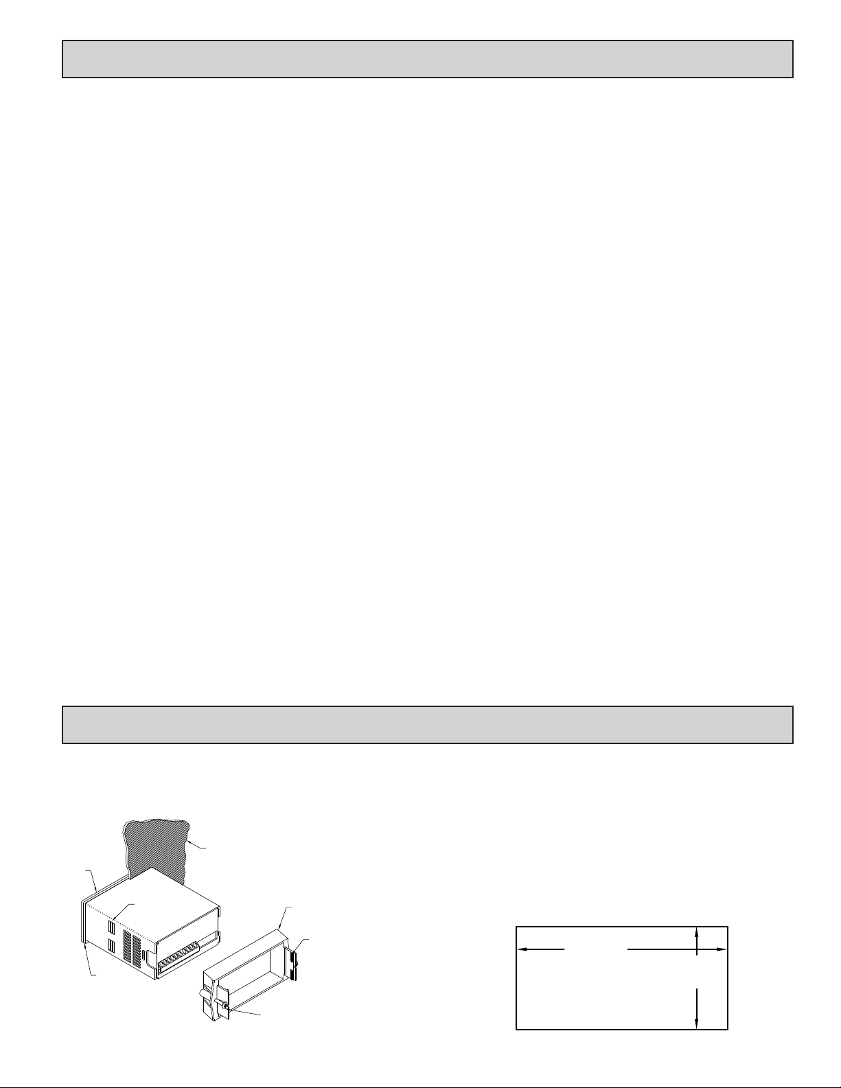
1.0 INSTALLING THE METER
Installation
The PAX Lite meets NEMA 4X/IP65 requirements when properly installed.
The unit is intended to be mounted into an enclosed panel. Prepare the panel
cutout to the dimensions shown. Remove the panel latch from the unit. Slide the
panel gasket over the rear of the unit to the back of the bezel. The unit should
be installed fully assembled. Insert the unit into
the panel cutout.
While holding the unit in place, push
the panel latch over the rear of the unit
so that the tabs of the panel latch
engage in the slots on the case. The
panel latch should
be engaged in
the farthest
forward slot
possible. To
achieve a
proper seal,
tighten the
latch screws
evenly until the unit is snug in the panel (Torque to approximately 7 in-lbs [79Ncm]). Do not over-tighten the screws.
Installation Environment
The unit should be installed in a location that does not exceed the maximum
operating temperature and provides good air circulation. Placing the unit near
devices that generate excessive heat should be avoided.
The bezel should be cleaned only with a soft cloth and neutral soap product.
Do NOT use solvents. Continuous exposure to direct sunlight may accelerate the
aging process of the bezel.
Do not use tools of any kind (screwdrivers, pens, pencils, etc.) to operate the
keypad of the unit.
PANEL CUT-OUT
3
Page 4

2.0 SETTING THE SWITCHES
REAR TERMINALS
FRONT DISPLAY
115
INPUT SET-UP
DIP SWITCHES
230
POWER
SELECTION
SWITCH
3
1
2
5
4
ON
6
The meter has switches that must be checked and/or changed prior to applying
power. To access the power switch, remove the meter base from the case by firmly
squeezing and pulling back on the side rear finger tabs. This should lower the latch
below the case slot (which is located just in front of the finger tabs). It is
recommended to release the latch on one side, then start the other side latch.
Power Selection Switch
Setup DIP Switches
A DIP switch is at the rear of the meter. It is used
to set up the input, enable/disable programming and
front panel reset functions. For the correct input
setup, refer to 3.3 Wiring the Meter.
Switch 1
SNK.: Adds internal 7.8 K pull-up resistor to +12 VDC, I
Switch 2
SRC: Adds internal 3.9 Kpull-down resistor, 8 mA max. @ 30 VDC max.
Switch 3
HI Frequency: Removes damping capacitor and allows max. frequency.
LO Frequency: Limits input frequency to 50 Hz and input pulse widths to
Caution: Insure the AC power selection switch is set for the proper
voltage before powering-up the meter. The meter is shipped from
the factory in the 230 VAC position.
SNK.
ON
1
Not Active
10 msec.
DIS PGM
MAG
SRC.
LO Freq.
3
5
2
4
EN PGM
LOGIC
Not Active
HI Freq.
Factory Setting
= 1.9 mA
MAX
DIS RST
6
EN RST
Switch 4
LOGIC: Input trigger levels V
MAG: Not used for count applications.
= 1.5 V max; VIH = 3.75 V max.
IL
Switch 5
Enable Programming: Enables programming through the front panel
buttons.
Disables Programming: Disables the front panel buttons from any
programming changes.
Switch 6
Enable Reset: Enables the front panel reset (down arrow key).
Disable Reset: Disables the front panel reset key. Note: The remote reset
terminal is not disabled by this switch.
3.0 WIRING THE METER
WIRING OVERVIEW
Electrical connections are made via screw-clamp terminals located on the
back of the meter. All conductors should conform to the meter’s voltage and
current ratings. All cabling should conform to appropriate standards of good
installation, local codes and regulations. It is recommended that the power
supplied to the meter (DC or AC) be protected by a fuse or circuit breaker.
When wiring the meter, compare the numbers embossed on the back of the
meter case against those shown in wiring drawings for proper wire position. Strip
the wire, leaving approximately 0.3" (7.5 mm) bare lead exposed (stranded wires
should be tinned with solder.) Insert the lead under the correct screw-clamp
terminal and tighten until the wire is secure. (Pull wire to verify tightness.)
EMC INSTALLATION GUIDELINES
Although this meter is designed with a high degree of immunity to ElectroMagnetic Interference (EMI), proper installation and wiring methods must be
followed to ensure compatibility in each application. The type of the electrical
noise, source or coupling method into the meter may be different for various
installations. The meter becomes more immune to EMI with fewer I/O
connections. Cable length, routing, and shield termination are very important
and can mean the difference between a successful or troublesome installation.
Listed below are some EMC guidelines for successful installation in an
industrial environment.
1. The meter should be mounted in a metal enclosure, which is properly
connected to protective earth.
2. Use shielded (screened) cables for all Signal and Control inputs. The shield
(screen) pigtail connection should be made as short as possible. The
connection point for the shield depends somewhat upon the application.
Listed below are the recommended methods of connecting the shield, in order
of their effectiveness.
a. Connect the shield only at the panel where the unit is mounted to earth
ground (protective earth).
b. Connect the shield to earth ground at both ends of the cable, usually when
the noise source frequency is above 1 MHz.
c. Connect the shield to common of the meter and leave the other end of the
shield unconnected and insulated from earth ground.
3. Never run Signal or Control cables in the same conduit or raceway with AC
power lines, conductors feeding motors, solenoids, SCR controls, and
heaters, etc. The cables should be run in metal conduit that is properly
grounded. This is especially useful in applications where cable runs are long
and portable two-way radios are used in close proximity or if the installation
is near a commercial radio transmitter.
4. Signal or Control cables within an enclosure should be routed as far as possible
from contactors, control relays, transformers, and other noisy components.
5. In extremely high EMI environments, the use of external EMI suppression
devices, such as ferrite suppression cores, is effective. Install them on Signal
and Control cables as close to the unit as possible. Loop the cable through the
core several times or use multiple cores on each cable for additional protection.
Install line filters on the power input cable to the unit to suppress power line
interference. Install them near the power entry point of the enclosure. The
following EMI suppression devices (or equivalent) are recommended:
Ferrite Suppression Cores for signal and control cables:
Fair-Rite # 0443167251 (RLC# FCOR0000)
TDK # ZCAT3035-1330A
Steward # 28B2029-0A0
Line Filters for input power cables:
Schaffner # FN610-1/07 (RLC# LFIL0000)
Schaffner # FN670-1.8/07
Corcom # 1 VR3
Note: Reference manufacturer’s instructions when installing a line filter.
6. Long cable runs are more susceptible to EMI pickup than short cable runs.
Therefore, keep cable runs as short as possible.
7. Switching of inductive loads produces high EMI. Use of snubbers across
inductive loads suppresses EMI.
Snubber: RLC# SNUB0000.
4
Page 5

3.1 POWER WIRING
3 4
DC OUT/IN
COMM
+
-
COMM
6
STORE
INHIBIT
RST
UP/ DOWN
7 8 109
AC Power
Terminal 1: VAC
Terminal 2: VAC
AC
DC Power
Terminal 3: +VDC
Terminal 4: COMM
AC
1 2
3.2 CONTROL INPUT WIRING
The PAXLC provides a number of control inputs, including Store, Reset,
Inhibit and Up/Down control. These inputs are active low (connected to
common), so the external switching device should be connected between the
control input and common terminals.
Up/Down - This input determines the direction of the count. Unconnected,
the meter will count up. When input is pulled low, the meter will count down.
Reset - When this input is pulled low , the meter will reset to zero. If the input
remains low or connected to common, the meter will be held in the reset mode,
and not able to count.
Inhibit - When low, this input will prevent the meter from counting. If the
input remains low or connected to the common, the meter will not be able to
count.
Store - A low will stop the display from updating. It will freeze the display
as long as the input is held low. Once released the display will update to the
current count display.
3.3 INPUT WIRING
Two Wire Proximity, Current Source
ON
INPUT
COMM
DC OUT/IN
1
43 5
2.2K
Interfacing With TTL
COMM
43 5
INPUT
DIODE
DC OUT/IN
Emitter Follower; Current Source
COMM
INPUT
DC OUT/IN
3 4 5
2
ON
*
1
3
4
2
ON
*
1
3 4
2
Current Sinking Output
*
DC OUT/IN
43
COMM
3 4 5
INPUT
ON
1
*
3
2
NPN O.C.
4
Current Sourcing Output
INPUT
COMM
DC OUT/IN
3 4 5
ON
1
*
3
2
PNP O.C.
4
Switch or Isolated Transistor; Current Sink Switch or Isolated Transistor; Current Source
+5V
COMM
DC OUT/IN
COMM
3 4 5
INPUT
ON
*
1
324
DC OUT/IN
COMM
3 4 5
INPUT
ON
*
1
3 4
2
*Switch position is application dependent.
5
Page 6

4.0 REVIEWING THE FRONT BUTTONS AND DISPLAY
PAR
PROGRAMMING MODE OPERATIONDISPLAY MODE OPERATIONKEY
Access Programming ModePAR
No Function
Front Panel Reset
Store selected parameter and index to next parameter
Increment selected digit of parameter value
Select digit position in parameter value
5.0 SCALING THE METER
In many industrial applications, a meter is required to totalize the output of an
operation or event. The pulses from a sensor are received by the PAXLC, and
then totalized on the display. In many cases the incoming pulses do not represent
the desired display readout. For those applications, a scale factor can be entered
into the meter, scaling the pulses to obtain the desired readout. The following
formula will help provide the scaling values to achieve the desired readout.
SF = DR
EPU
WHERE:
SF = Scale Factor
DR = Desired Readout* (Single unit of measure, i.e. foot, gallon, etc.)
EPU = Existing Pulses per Unit (Number of pulses per single unit of
measure, i.e. foot, gallons, etc.)
*For applications requiring a decimal point, select and program the
appropriate decimal point. When calculating the Scale Factor, use the whole
value of the number to be displayed, for example, 1.0 feet, the Desired
Readout in this case is 10. Do not use decimal points in the Scaling Formula.
For calculated SF values less than 9.99999
If the Scale Factor is a value less than 9.99999, it can be entered directly
into the meter as the Scale Factor and the Scale Multiplier can be left at 1.
For calculated SF values greater than 9.99999
If the Scale Factor is a value over 9.99999 (maximum value), the Scale
Multiplier must be used to reduce the calculated SF value until it is less then
9.99999. The Scale Multiplier multiplies the calculated Scale Factor value by
1, 0.1, and 0.01, thus reducing the calculated value accordingly. Select the
appropriate Scale Multiplier value that allows the Scale Factor to be a value
under 9.99999. Both the Scale Factor and Scale Multiplier can then be
entered into the meter.
Example 1:
This application involves counting cases from a production line. The sensor
provides a pulse for every can produced. The desired readout is in cases,
therefore the incoming pulses need to be converted to obtain the proper readout.
The following is used to calculate scale factor.
SF = DR
EPU
DR = 1 case
EPU = 12 cans/case
SF = 1
12
SF = 0.083333
Since the Calculated Scale Factor Value is less than 9.99999, it can be
entered directly into the meter. The Scale Multiplier can be left at 1.
6
Page 7

Decimal
Position
PAR
Scale
Factor
PAR
Scale
Multiplier
PAR
PAR
COUNTER
DISPLAY
Power-Up
PAR
COUNTER
DISPLAY
6.0 PROGRAMMING THE METER
PROGRAMMING SEQUENCE
The Totalizer has four programmable parameters which are entered in the
sequence shown above, using the front panel push buttons.
Before programming, refer to the section on Scaling the Meter to determine
the Decimal Position, Scale Factor and Scale Multiplier to use for the specific
application.
Note: Programming mode can be locked out with the Program Disable DIP
switch. With the switch in the Disabled (up) position the meter will not enter
programming mode. Refer to the section on DIP switch setup.
PROGRAMMING MODE ENTRY
Press the PAR key to enter Programming Mode. The meter briefly displays
followed by the first programming parameter described below.
PROGRAMMING PARAMETERS
In programming mode, the display alternates between the parameter and the
current selection or value for that parameter. The dual display with arrows is
used below to illustrate the alternating display. The selection choices or value
range for each parameter is shown to the right of the alternating display.
DECIMAL POSITION
display.
Press the arrow keys ( or ) to sequence through the selection list until the
desired selection is shown. Press the PAR key to save the displayed selection
and advance to the next parameter.
Factor and the Scale Multiplier to obtain the desired process value. A Scale
Factor of 1.00000 and a Scale Multiplier of 1 will result in the display of the
actual number of input counts. (See details on scaling calculations.)
The Scale Factor is displayed as a six-digit value with one selected digit
flashing (initially digit 6). Press the (up arrow) key to increment the value of
the selected (flashing) digit. Holding the key automatically scrolls the value
of the selected digit.
Press the (down arrow) key to select the next digit position to the right.
Use the key to increment the value of this digit to the desired number. Press
the key again to select the next digit to be changed. Holding the key
automatically scrolls through each digit position. Repeat the “select and set”
sequence until all digits are displaying the desired Scale Factor value. Press the
PAR key to save the displayed value and advance to the next parameter.
This parameter selects the decimal point position on the
SCALE FACTOR
to
The number of input counts is multiplied by the Scale
SCALE MULTIPLIER
The number of input counts is multiplied by the Scale Multiplier and the
Scale Factor to obtain the desired process value. A Scale Multiplier of 1 will
result in only the Scale Factor affecting the display. (See details on scaling
calculations.)
Press the arrow keys ( or ) to sequence through the selection list until the
desired selection is displayed. Press the PAR key to save the selection and exit
programming mode.
The totalizer may be programmed to reset at each meter power-up.
COUNTER RESET AT POWER-UP
PROGRAMMING MODE EXIT
The meter exits Programming Mode when the PAR key is pressed to save the
Scale Multiplier selection. The meter briefly displays upon exiting
Programming Mode. All programmed selections are now transferred to the nonvolatile memory and the meter returns to the Counter display.
(If power loss occurs during programming mode, verify parameter changes
and reprogram, if necessary, when power is restored.)
PROGRAMMING MODE TIME OUT
The Programming Mode has an automatic time out feature. If no keypad
activity is detected for approximately 60 seconds, the meter automatically exits
Programming Mode. The meter briefly displays and returns to the Counter
display. When automatic timeout occurs, any changes that were made to the
parameter currently being programmed, will not be saved.
FACTORY SETTINGS
The factory settings for the programming parameters are shown above in the
alternating display illustrations. The factory settings can be easily restored by
removing power from the meter, and then pressing and holding the PAR key
while power is reapplied. The meter displays until the PAR key is
released. The normal power-up sequence then resumes, with the factory settings
loaded and saved in non-volatile memory. The Count is reset to 0.
Note: The Program Disable DIP switch must be in the Enabled (down)
position to allow loading factory settings. See section on DIP switch setup.
7
Page 8

The Company warrants the products it manufactures against defects in materials and workmanship
LIMITED WARRANTY
for a period limited to two years from the date of shipment, provided the products have been stored,
handled, installed, and used under proper conditions. The Company’s liability under this limited
warranty shall extend only to the repair or replacement of a defective product, at The Company’s
option. The Company disclaims all liability for any affirmation, promise or representation with
respect to the products.
The customer agrees to hold Red Lion Controls harmless from, defend, and indemnify RLC against
damages, claims, and expenses arising out of subsequent sales of RLC products or products
containing components manufactured by RLC and based upon personal injuries, deaths, property
damage, lost profits, and other matters which Buyer, its employees, or sub-contractors are or may be
to any extent liable, including without limitation penalties imposed by the Consumer Product Safety
Act (P.L. 92-573) and liability imposed upon any person pursuant to the Magnuson-Moss Warranty
Act (P.L. 93-637), as now in effect or as amended hereafter.
No warranties expressed or implied are created with respect to The Company’s products except those
expressly contained herein. The Customer acknowledges the disclaimers and limitations contained
herein and relies on no other warranties or affirmations.
 Loading...