

Page 1
Tel +1 (717) 767-6511
Fax +1 (717) 764-0839
www.redlion.net
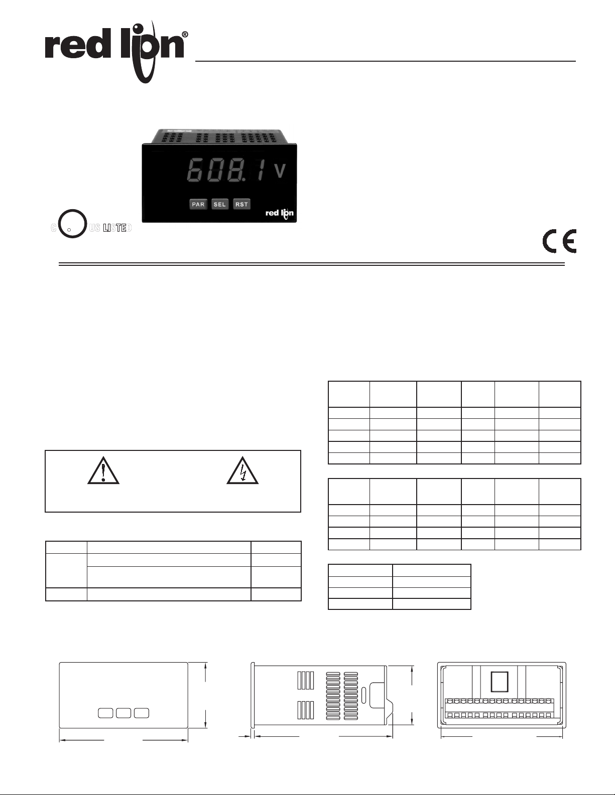
MODEL PAXLA - PAX LITE DC VOLT/CURRENT/PROCESS METER
5 DIGIT, 0.56" HIGH RED LED DISPLAY
PROGRAMMABLE SCALING AND DECIMAL POINTS
PROGRAMMABLE USER INPUT
DUAL 5 AMP FORM C RELAY
UNIVERSALLY POWERED
NEMA 4X/IP65 SEALED FRONT BEZEL
U
R
C
US LISTED
L
IND. CONT. EQ.
51EB
For Model No. PAXLA0U0 Only
OPTIONAL CUSTOM UNIT OVERLAY W/ BACKLIGHT
MINIMUM AND MAXIMUM DISPLAY CAPTURE
Bulletin No. PAXLA-D
Drawing No. LP0722
Released 04/14
GENERAL DESCRIPTION
The PAXLA is a versatile meter available as a DC volt, current, or process
meter with scaling and dual Form C relay outputs. The meter is programmed
through the front panel buttons and the use of jumpers. The RST Key will also
function as a front panel display reset.
Once the front panel programming is complete, the buttons can be disabled
by a user input setting. The meter has been specifically designed for harsh
industrial environments. With a NEMA 4X/IP65 sealed bezel and extensive
testing to meet CE requirements, the meter provides a tough yet reliable
application solution.
SAFETY SUMMARY
All safety regulations, local codes and instructions that appear in this and
corresponding literature, or on equipment, must be observed to ensure personal
safety and to prevent damage to either the instrument or equipment connected to
it. If equipment is used in a manner not specified by the manufacturer, the
protection provided by the equipment may be impaired.
CAUTION: Risk of Danger.
Read complete instructions prior to
installation and operation of the unit.
CAUTION: Risk of electric shock.
ORDERING INFORMATION
MODEL NO. DESCRIPTION PART NUMBER
Volt/Current/Process Meter with Dual Relay Output PAXLA000
PAXLA
PAXLBK Unit Label Kit Accessory PAXLBK10
UL Listed Volt/Current/Process Meter with Dual
Relay Output
PAXLA0U0
SPECIFICATIONS
1. DISPLAY: 5 digit, 0.56" (14.2 mm) intensity adjustable Red LED (-19999 to
99999)
2. POWER REQUIREMENTS:
AC POWER: 50 to 250 VAC 50/60 Hz, 12 VA
Isolation: 2300 Vrms for 1 min. to all inputs and outputs
DC POWER: 21.6 to 250 VDC, 6 W
DC Out: +24 VDC @ 100 mA if input voltage is greater than 50 VAC/VDC
+24 VDC @ 50 mA if input voltage is less than 50 VDC
3. INPUT RANGES: Jumper Selectable
D.C. Voltages: 200 mV, 2 V, 20 V, 200 V, 10 V
INPUT
RANGE
200 mV 0.1% of span
10 V 0.1% of span
20 V 0.1% of span
200 V 0.1% of span
ACCURACY @
23 °C LESS
THAN 85% RH
2 V 0.1% of span
INPUT
IMPEDANCE
1.033 MΩ
1.033 MΩ
1.033 MΩ
1.033 MΩ
1.033 MΩ
D.C. Currents: 200 µA, 2 mA, 20 mA, 200 mA
INPUT
RANGE
200 µΑ 0.1% of span
2 mA 0.1% of span
20 mA 0.1% of span
200 mA 0.1% of span
ACCURACY @
23 °C LESS
THAN 85% RH
INPUT
IMPEDANCE
1.111 KΩ
111 Ω
11 Ω
1 Ω
D.C. Process: 4 to 20 mA, 1 to 5 VDC, 0/1 to 10 VDC
INPUT RANGE SELECT RANGE
4 - 20 mA Use the 20 mA range
1 - 5 VDC Use the 10V range
1 - 10 VDC Use the 10V range
MAX
INPUT
SIGNAL
75 VDC 10 µV 70 ppm /°C
75 VDC 0.1 mV 70 ppm /°C
250 VDC 1 mV 70 ppm /°C
250 VDC 1 mV 70 ppm /°C
250 VDC 10 mV 70 ppm /°C
SIGNAL
150 mA 1 µA 70 ppm /°C
500 mA 10 µA 70 ppm /°C
RESOLUTION
MAX
INPUT
RESOLUTION
15 mA 10 nA 70 ppm /°C
50 mA 0.1 µA 70 ppm /°C
TEMP.
COEFFICIENT
TEMP.
COEFFICIENT
DIMENSIONS In inches (mm)
A
X
M
IMN
8.8.8.8.8
S
PS1P
2
SEL RST
PAR
3.80
(96.5)
V
1.95
(49.5)
.10
(2.5)
4.10
(104.1)
1
1.75
(44.5)
1
5
6
2
3
7
8
9
4
10
11
15
12
13
14
3.60 (91.4)
Page 2
4. OVERRANGE/UNDERRANGE INDICATION:
Input Overrange Indication: “OLOL”.
Input Underrange Indication: “ULUL”.
Display Overrange/Underrange Indication: “.....”/“-.....”
5. A/D CONVERTER: 16 bit resolution
6. UPDATE RATES:
A/D conversion rate: 20 readings/sec.
Display update: 500 msec min.
7. USER INPUT:
User Input: Software selectable pull-up (24.7 KΩ) or pull-down resistor
(20 KΩ) that determines active high or active low input logic.
Trigger levels: VIL = 1.0 V max; VIH = 2.4 V min; V
Response Time: 5 msec typ.; 100 msec debounce (activation and release)
MAX
= 28 VDC
8. MEMORY: Nonvolatile E2PROM retains all programming parameters when
power is removed.
9. OUTPUT:
Type: Dual FORM-C relay
Isolation To Sensor & User Input Commons: 1400 Vrms for 1 min.
Working Voltage: 150 Vrms
Contact Rating: 5 amps @ 120/240 VAC or 28 VDC (resistive load), 1/8
H.P. @ 120 VAC (inductive load)
Life Expectancy: 100,000 minimum operations
Response Time:
Turn On Time: 4 msec max.
Turn Off Time: 4 msec max.
10. ENVIRONMENTAL CONDITIONS:
Operating temperature: 0 to 50 °C
Storage temperature: -40 to 70 °C
Operating and storage humidity: 0 to 85% max. RH (non-condensing)
Vibration to IEC 68-2-6: Operational 5 to 150 Hz, 2g.
Shock to IEC 68-2-27: Operational 30 g (10g relay).
Altitude: Up to 2,000 meters
11. CONNECTIONS: High compression cage-clamp terminal block
Wire Strip Length: 0.3" (7.5 mm)
Wire Gage: 30-14 AWG copper wire
Torque: 4.5 inch-lbs (0.51 N-m) max.
12. CONSTRUCTION: This unit is rated for NEMA 4X/IP65 outdoor use. IP20
Touch safe. Installation Category II, Pollution Degree 2. One piece bezel/
case. Flame resistant. Synthetic rubber keypad. Panel gasket and mounting
clip included.
13. CERTIFICATIONS AND COMPLIANCES:
CE Approved
EN 61326-1 Immunity to Industrial Locations
Emission CISPR 11 Class A
Safety requirements for electrical equipment for measurement, control, and
laboratory use:
EN 61010-1: General Requirements
RoHS Compliant
UL Listed: File #E137808 For Model No. PAXLA0U0 Only
Type 4X Enclosure rating (Face only)
IP65 Enclosure rating (Face only)
IP20 Enclosure rating (Rear of unit)
14. WEIGHT: 10.4 oz. (295 g)
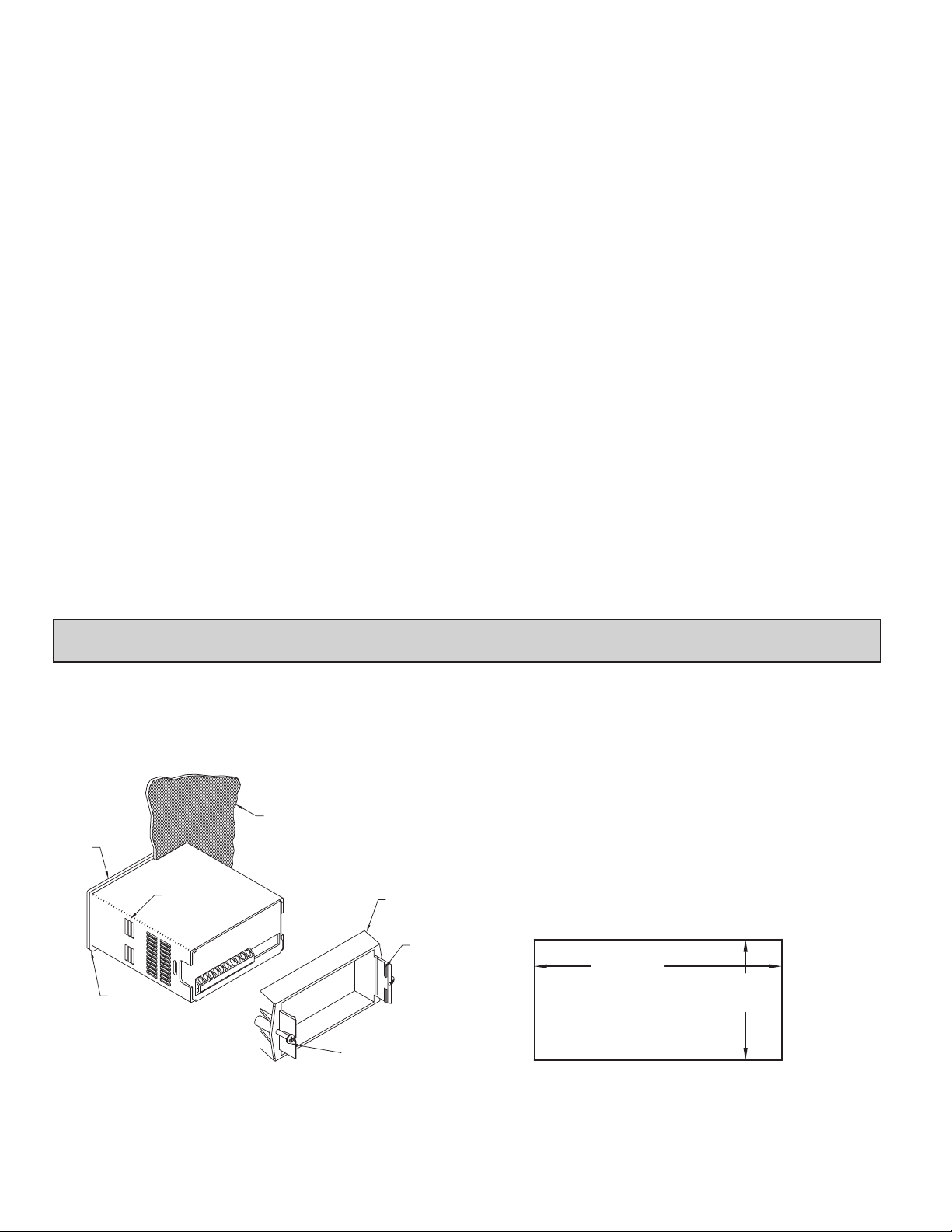
1.0 InstallIng the Meter
Installation
The PAX meets NEMA 4X/IP65 requirements when properly installed. The
unit is intended to be mounted into an enclosed panel. Prepare the panel cutout
to the dimensions shown. Remove the panel latch from the unit. Slide the panel
gasket over the rear of the unit to the back of the bezel. The unit should be
installed fully assembled. Insert the unit into the panel cutout.
PANEL
BEZEL
PANEL
GASKET
LATCHING
SLOTS
PANEL
MOUNTING
SCREWS
PANEL
LATCH
LATCHING
TABS
While holding the unit in place, push the panel latch over the rear of the unit
so that the tabs of the panel latch engage in the slots on the case. The panel latch
should be engaged in the farthest forward slot possible. To achieve a proper seal,
tighten the latch screws evenly until the unit is snug in the panel (Torque to
approximately 7 in-lbs [79N-cm]). Do not over-tighten the screws.
Installation Environment
The unit should be installed in a location that does not exceed the maximum
operating temperature and provides good air circulation. Placing the unit near
devices that generate excessive heat should be avoided.
The bezel should be cleaned only with a soft cloth and neutral soap product.
Do NOT use solvents. Continuous exposure to direct sunlight may accelerate the
aging process of the bezel.
Do not use tools of any kind (screwdrivers, pens, pencils, etc.) to operate the
keypad of the unit.
PANEL CUT-OUT
+.03
3.62
-.00
+.8
(92 )
-.0
+.02
1.77
+.5
(45 )
-.00
-.0
2
Page 3
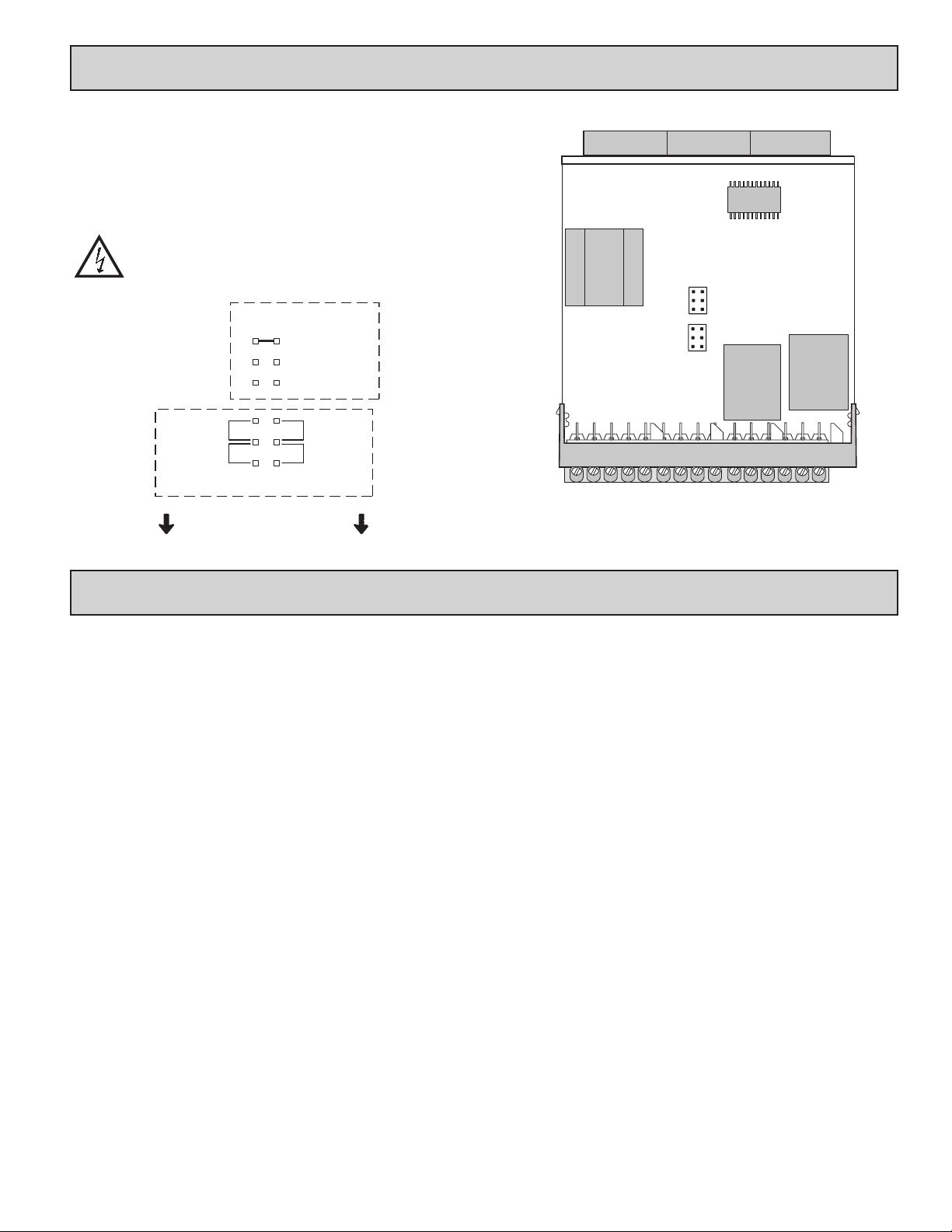
2.0 settIng the JuMpers
INPUT RANGE JUMPER
This jumper is used to select the proper input range. The input range selected
in programming must match the jumper setting. Select a range that is high
enough to accommodate the maximum signal input to avoid overloads.
To access the jumpers, remove the meter base from the case by firmly
squeezing and pulling back on the side rear finger tabs. This should lower the
latch below the case slot (which is located just in front of the finger tabs). It is
recommended to release the latch on one side, then start on the other side latch.
Warning: Exposed line voltage exists on the circuit boards.
Remove all power to the meter and load circuits before accessing
inside of the meter.
VOLT
INPUT
RANGES
20 V/200 V
10 V
200 mV/2 V
20 mA
200 mA
2 mA
200 µA
CURRENT
REAR TERMINALS
FRONT DISPLAY
Main
Circuit
Board
INPUT RANGE
JUMPER LOCATION
VOLT
CURRENT
REAR TERMINALS
3.0 WIrIng the Meter
EMC INSTALLATION GUIDELINES
Although Red Lion Controls Products are designed with a high degree of
immunity to Electromagnetic Interference (EMI), proper installation and wiring
methods must be followed to ensure compatibility in each application. The type
of the electrical noise, source or coupling method into a unit may be different
for various installations. Cable length, routing, and shield termination are very
important and can mean the difference between a successful or troublesome
installation. Listed are some EMI guidelines for a successful installation in an
industrial environment.
1. A unit should be mounted in a metal enclosure, which is properly connected
to protective earth.
2. Use shielded cables for all Signal and Control inputs. The shield connection
should be made as short as possible. The connection point for the shield
depends somewhat upon the application. Listed below are the recommended
methods of connecting the shield, in order of their effectiveness.
a. Connect the shield to earth ground (protective earth) at one end where the
unit is mounted.
b. Connect the shield to earth ground at both ends of the cable, usually when
the noise source frequency is over 1 MHz.
3. Never run Signal or Control cables in the same conduit or raceway with AC
power lines, conductors, feeding motors, solenoids, SCR controls, and
heaters, etc. The cables should be run through metal conduit that is properly
grounded. This is especially useful in applications where cable runs are long
and portable two-way radios are used in close proximity or if the installation
is near a commercial radio transmitter. Also, Signal or Control cables within
an enclosure should be routed as far away as possible from contactors, control
relays, transformers, and other noisy components.
4. Long cable runs are more susceptible to EMI pickup than short cable runs.
5. In extremely high EMI environments, the use of external EMI suppression
devices such as Ferrite Suppression Cores for signal and control cables is
effective. The following EMI suppression devices (or equivalent) are
recommended:
Fair-Rite part number 0443167251 (RLC part number FCOR0000)
Line Filters for input power cables:
Schaffner # FN2010-1/07 (Red Lion Controls # LFIL0000)
6. To protect relay contacts that control inductive loads and to minimize radiated
and conducted noise (EMI), some type of contact protection network is
normally installed across the load, the contacts or both. The most effective
location is across the load.
a. Using a snubber, which is a resistor-capacitor (RC) network or metal oxide
varistor (MOV) across an AC inductive load is very effective at reducing
EMI and increasing relay contact life.
b. If a DC inductive load (such as a DC relay coil) is controlled by a transistor
switch, care must be taken not to exceed the breakdown voltage of the
transistor when the load is switched. One of the most effective ways is to
place a diode across the inductive load. Most RLC products with solid state
outputs have internal zener diode protection. However external diode
protection at the load is always a good design practice to limit EMI.
Although the use of a snubber or varistor could be used.
RLC part numbers: Snubber: SNUB0000
Varistor: ILS11500 or ILS23000
7. Care should be taken when connecting input and output devices to the
instrument. When a separate input and output common is provided, they
should not be mixed. Therefore a sensor common should NOT be connected
to an output common. This would cause EMI on the sensitive input common,
which could affect the instrument’s operation.
Visit RLC’s web site at http://www.redlion.net/Support/InstallationConsiderations.
html for more information on EMI guidelines, Safety and CE issues as they
relate to Red Lion Controls products.
WIRING OVERVIEW
Electrical connections are made via screw-clamp terminals located on the
back of the meter. All conductors should conform to the meter’s voltage and
current ratings. All cabling should conform to appropriate standards of good
installation, local codes and regulations. It is recommended that the power
supplied to the meter (DC or AC) be protected by a fuse or circuit breaker.
When wiring the meter, compare the numbers embossed on the back of the
meter case against those shown in wiring drawings for proper wire position. Strip
the wire, leaving approximately 0.3" (7.5 mm) bare lead exposed (stranded wires
should be tinned with solder.) Insert the lead under the correct screw-clamp
terminal and tighten until the wire is secure. (Pull wire to verify tightness.)
3
Page 4
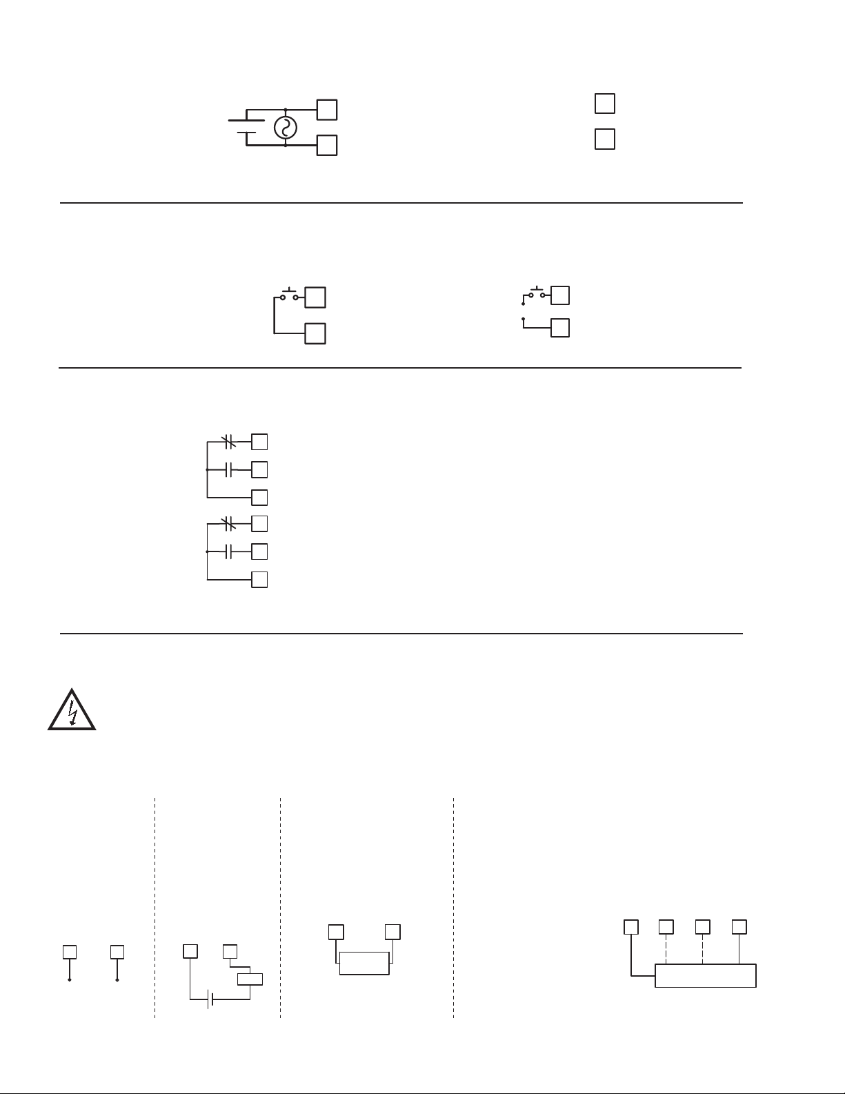
3.1 POWER WIRING
Power
Terminal 1: VAC/DC +
Terminal 2: VAC/DC -
+
-
L1
1
2
L2
3.2 USER INPUT WIRING
Terminal 8: User Input
Terminal 9: User Comm
Sinking Logic Sourcing Logic
8
USER
9
USER COM
3.3 SETPOINT (OUTPUT) WIRING
N.C. 1
Terminal 10: NC 1
Terminal 11: NO 1
Terminal 12: Relay 1 Common
Terminal 13: NC 2
Terminal 14: NO 2
Terminal 15: Relay 2 Common
10
11
12
13
N.O. 1
COMM 1
N.C. 2
DC Out Power
Terminal 3: + 24 VDC OUT
Terminal 4: Common
+
-
3
4
8
USER
9
USER COMM
+ EXC
COMM
14
N.O. 2
COMM 2
15
3.4 INPUT SIGNAL WIRING
CAUTION: Analog common is NOT isolated from user input common. In order to preserve the safety of the meter
application, the Analog and DC power common must be suitably isolated from hazardous live earth referenced voltage; or
input common must be at protective earth ground potential. If not, hazardous voltage may be present at the User Input and
Input Common terminals. Appropriate considerations must then be given to the potential of the input common with respect
to earth ground. Always connect the analog signal common to terminal 7.
Voltage Signal
(self powered)
Terminal 5: +VDC
Terminal 7: -VDC
VOLT
5 7
+
200 VDC MAX.
ANALOG COMM
-
Current Signal
(self powered)
Terminal 6: +ADC
Terminal 7: -ADC
ANALOG COMM
CURRENT
6
7
Load
+
-
200 MA DC MAX.
Current Signal (2 wire
requiring excitation)
Terminal 3: +EXC
Terminal 6: +ADC
+ EXC.
3
2 WIRE
+
TRANSMITTER
CURRENT
6
-
Current Signal (3 wire
requiring excitation)
Terminal 6: +ADC (signal)
Terminal 7: -ADC (common)
Terminal 3: +EXC
Voltage Signal (3 wire
requiring excitation)
Terminal 5: +VDC (signal)
Terminal 7: -VDC (common)
Terminal 3: +EXC
VOLT
+ EXC.
5
3
3 WIRE TRANSMITTER
CURRENT
6 7
IoutVout
ANALOG COMM
COMM
4
Page 5

4.0 revIeWIng the Front Buttons and dIsplay
Display
Readout
Legends*
Setpoint Alarm
Annunciators
BUTTON DISPLAY MODE OPERATION PROGRAMMING MODE OPERATION
PAR Access Programming Mode Store selected parameter and index to next parameter
SEL
Index display through selected displays
RST
Resets display
A
X
M
NMI
8.8.8.8.8
S
P1SP
2
PAR
V
RSTSEL
Advance through selection list/select digit position in
parameter value
Increment selected digit of parameter value
Optional Custom
Units Overlay
OPERATING MODE DISPLAY DESIGNATORS
MAX - Maximum display capture value
MIN - Minimum display capture value
Pressing the SEL button toggles the meter through the selected displays. If display scroll is enabled, the display will toggle automatically every four seconds between
the enabled display values.
“SP1” - Below the display indicates setpoint 1 output activated.
“SP2” - Below the display indicates setpoint 2 output activated.
5.0 prograMMIng the Meter
DISPLAY
MODE
PAR
NO
Signal Input
Pro
Parameters
RST
PAR PAR PARPAR
1-INP
PROGRAMMING MODE ENTRY (PAR BUTTON)
It is recommended all programming changes be made off line, or before
installation. The meter normally operates in the Display Mode. No parameters
can be programmed in this mode. The Programming Mode is entered by
pressing the PAR button. If it is not accessible, then it is locked by either a
security code or a hardware lock.
MODULE ENTRY (SEL & PAR BUTTONS)
The Programming Menu is organized into four modules. These modules group
together parameters that are related in function. The display will alternate between
and the present module. The SEL button is used to select the desired module.
The displayed module is entered by pressing the PAR button.
MODULE MENU (PAR BUTTON)
Each module has a separate module menu (which is shown at the start of each
module discussion). The PAR button is pressed to advance to a particular
parameter to be changed, without changing the programming of preceding
parameters. After completing a module, the display will return to .
Programming may continue by accessing additional modules.
SELECTION / VALUE ENTRY
For each parameter, the display alternates between the present parameter and
the selections/value for that parameter. The SEL and RST buttons are used to
move through the selections/values for that parameter. Pressing the PAR button,
stores and activates the displayed selection/value. This also advances the meter to
the next parameter.
For numeric values, the value is displayed with one digit flashing (initially
the right most digit). Pressing the RST button increments the digit by one or the
user can hold the RST button and the digit will automatically scroll. The SEL
button will select the next digit to the left. Pressing the PAR button will enter the
value and move to the next parameter.
OVERVIEW
PROGRAMMING MENU
Secondary
Function
Parameters
2-SEC
Display and Front
Panel Key
Parameters
3-dSP
PROGRAMMING MODE EXIT (PAR BUTTON)
The Programming Mode is exited by pressing the PAR button with Pro NO
displayed. This will commit any stored parameter changes to memory and
return the meter to the Display Mode. (If power loss occurs before returning to
the Display Mode, verify recent parameter changes.)
PROGRAMMING TIPS
It is recommended to start with Module 1 and proceed through each module in
sequence. When programming is complete, it is recommended to record the
parameter programming and lock out parameter programming with the user input
or programming security code.
FACTORY SETTINGS
Factory Settings may be completely restored in Module 2. This is useful
when encountering programming problems.
ALTERNATING SELECTION DISPLAY
In the explanation of the modules, the following dual display with arrows will
appear. This is used to illustrate the display alternating between the parameter
on top and the parameter’s Factory Setting on the bottom. In most cases,
selections and values for the parameter will be listed on the right.
Setpoint
Output
Parameters
4-SPt
Indicates Program Mode Alternating Display
Parameter
USrIN
Factory Settings are shown.
N0
Selection/Value
5
Page 6

5.1 Module 1 - sIgnal Input paraMeters (1-INP)
1-INP
PAR
rANGE
Input
Range
rAN6E
Select the input range that corresponds to the external signal. This selection
should be high enough to avoid input signal overload but low enough for the
desired input resolution. This selection and the position of the Input Range
Jumper must match.
dECPt
Select the decimal point location for the Input, MIN and MAX displays. This
selection also affects the dSP1 and dSP2 parameters and setpoint values and
offset value..
200v
0.00
dECPt
Display
Decimal
Point
OFSEt
Display
Offset
Value
INPUT RANGE
SELECTION
200uA
0.002A
0.2u
2u
10u
DISPLAY DECIMAL POINT
FILtr
Filter
Setting
RANGE
RESOLUTION
200.00 µA
2.0000 mA
200.00 mV
2.0000 V
10.000 V
bANd
Filter
Band
SELECTION
PARAMETER MENU
INP 1
Input Value
for Scaling
Point 1
RANGE
RESOLUTION
20.000 mA
200.00 mA
20.000 V
200.00 V
0.02A
0.2A
20u
200u
StYLE
Scaling
Style
0.000 0.00000.000.00
Pro
dSP 1
Display Value
For Scaling
Point 1
StYLE
If Input Values and corresponding Display Values are known, the Key-in
(KEY) scaling style can be used. This allows scaling without the presence or
changing of the input signal. If Input Values have to be derived from the actual
input signal source or simulator, the Apply (APLY) scaling style must be used.
INP 1
For Key-in (KEY) style, enter the first Input Value using the front panel buttons.
(The Input Range selection sets the decimal location for the Input Value).
For Apply (APLY) style, the meter shows the previously stored Input Value.
To retain this value, press the SEL button to advance to the next parameter. To
change the Input Value, press the RST button and apply the input signal to the
meter. Adjust the signal source externally until the desired Input Value appears.
Press the SEL button to enter the value being displayed.
INP 2
Input Value
for Scaling
Point 2
KEy
INPUT VALUE FOR SCALING POINT 1
0.00
dSP 2
Display Value
For Scaling
Point 2
KEy APLY
0 to 29999
USrIN
User Input
Function
SCALING STYLE
User Input
Assignment
U-ASN
U-Act
User Input
Active Level
DISPLAY OFFSET VALUE
OFSEt
The display can be corrected with an offset value. This can be used to
compensate for signal variations or sensor errors. This value is automatically
updated after a Zero Display to show how far the display is offset. A value of
zero will remove the effects of offset. The decimal point follows the dECPt
selection.
FILtr
If the displayed value is difficult to read due to small process variations or
noise, increased levels of filtering will help to stabilize the display. Software
filtering effectively combines a fraction of the current input reading with a
fraction of the previous displayed reading to generate the new display.
Filter values represent no filtering (0), up to heavy filtering (3). A value of 1
for the filter uses 1/4 of the new input and 3/4 of the previous display to generate
the new display. A filter value of 2 uses 1/8 new and 7/8 previous. A filter value
of 3 uses 1/16 new and 15/16 previous.
bANd
The filter will adapt to variations in the input signal. When the variation
exceeds the input filter band value, the filter disengages. When the variation
becomes less than the band value, the filter engages again. This allows for a
stable readout, but permits the display to settle rapidly after a large process
change. The value of the band is in display units, independent of the Display
Decimal Point position. A band setting of ‘0’ keeps the filter permanently
engaged at the filter level selected above.
0.00
1
10
-19999 to 19999
FILTER SETTING
0,1 2 3
FILTER BAND
0 to 199 display units
DISPLAY VALUE FOR SCALING POINT 1
dSP 1
Enter the first Display Value by using the front panel buttons. This is the same
for KEY and APLY scaling styles. The decimal point follows the dECPt selection.
INP 2
For Key-in (KEY) style, enter the known second Input Value using the front
panel buttons.
For Apply (APLY) style, the meter shows the previously stored Input Value for
Scaling Point 2. To retain this value, press the SEL button to advance to the next
parameter. To change the Input Value, press the RST button and apply the input
signal to the meter. Adjust the signal source externally until the desired Input
Value appears. Press the SEL button to enter the value being displayed.
dSP 2
Enter the second Display Value by using the front panel buttons. This is the
same for KEY and APLY scaling styles. The decimal point follows the dECPt
selection.
General Notes on Scaling
1. When using the Apply (APLY) scaling style, input values for scaling points
must be confined to the range limits shown.
2. The same Input Value should not correspond to more than one Display Value.
(Example: 20 mA can not equal 0 and 20.)
3. For input levels beyond the programmed Input Values, the meter extends the
Display Value by calculating the slope from the two coordinate pairs (INP1 /
-19999 to 99999
0.00
INPUT VALUE FOR SCALING POINT 2
0 to 29999
100.00
DISPLAY VALUE FOR SCALING POINT 2
-19999 to 99999
100.00
dSP1 & INP2 / dSP2).
6
Page 7

USER INPUT FUNCTION
USER INPUT ASSIGNMENT
USrIN
P-Loc
ZErO
rESEt
d-HLd
d-SEL
d-LEV
rSt-1
rSt-2
rSt12
NO
MODEDISPLAY
No Function
NO
Program Mode Lock-out
Zero Input
(Edge triggered)
Reset (Edge triggered)
Display Hold
Display Select
(Edge Triggered)
Display Intensity Level
(Edge Triggered)
Setpoint 1 Reset
Setpoint 2 Reset
Setpoint 1 and 2 Reset
DESCRIPTION
User Input disabled.
See Programming Mode Access chart
(Module 3).
Zero the Input Display value causing
Display Reading to be Offset.
Resets the assigned value(s) to the current
input value.
Holds the assigned display, but all other
meter functions continue as long as
activated (maintained action).
Advance once for each activation.
Increase intensity one level for each
activation.
Resets setpoint 1 output.
Resets setpoint 2 output.
Reset both setpoint 1 and 2 outputs.
U-ASN
Select the value(s) to which the User Input Function is assigned. The User
Input Assignment only applies if a selection of reset, or display hold is selected
in the User Input Function menu.
U-Act
Select whether the user input is configured as active low or active high.
dSP
LO
HI-LO HI
dSPLO
USER INPUT ACTIVE LEVEL
LO HI
5.2 Module 2 - secondary FunctIon paraMeters (2-SEC)
2-SEC
PAR
HI-En HI-t
Max Display
Enable
Max Capture
Delay Time
PARAMETER MENU
LO-En LO-t FCS
Min Display
Enable
Min Capture
Delay TIme
Factory
Service
Operations
CodE
Access Code
For Service
Operations
Pro
MAX DISPLAY ENABLE
HI-En
Enables the Maximum Display Capture capability.
HI-t
When the Input Display is above the present MAX value for the entered
delay time, the meter will capture that display value as the new MAX reading.
A delay time helps to avoid false captures of sudden short spikes.
LO-En
Enables the Minimum Display Capture capability.
LO-t
When the Input Display is below the present MIN value for the entered delay
time, the meter will capture that display value as the new MIN reading. A delay
time helps to avoid false captures of sudden short spikes.
YESNO
NO
MAX CAPTURE DELAY TIME
0.0 to 999.9 sec.
2.0
MIN DISPLAY ENABLE
NO
MIN CAPTURE DELAY TIME
0.0 to 999.9 sec.
2.0
YESNO
FACTORY SERVICE OPERATIONS
FCS
Select yES to perform any of the Factory Service Operations shown below.
CodE
CodE
CodE
most applications, recalibration every 1 to 2 years should be sufficient.
Calibration of the PAXLA involves a calibration which should only be
performed by individuals experienced in calibrating electronic equipment. Allow
30 minute warm up before performing any calibration related procedure. The
following procedures should be performed at an ambient temperature of 15 to 35
°C (59 to 95 °F).
CAUTION: The accuracy of the calibration equipment will directly affect the
yESNO
NO
RESTORE FACTORY DEFAULT SETTINGS
66
50
48
accuracy of the PAXLA.
Entering Code 66 will overwrite all user settings with
the factory settings. The meter will display rESEt and then
return to CodE 00. Press the PAR button to exit the
module.
VIEW MODEL AND VERSION DISPLAY
Entering Code 50 will display the version (x.x) of the
meter. The display then returns to CodE 00. Press the PAR
button to exit the module.
CALIBRATION
The PAXLA uses stored calibration values to provide
accurate measurements. Over time, the electrical
characteristics of the components inside the PAXLA will
slowly change with the result that the stored calibration
values no longer accurately define the input circuit. For
7
Page 8

Current Calibration
1. Connect the negative lead of a precision DC current source with an accuracy
of 0.01% or better to the COMM terminal. Leave the positive lead of the DC
current source unconnected.
2. With the display at CodE 48, press the PA R button. Unit will display CAL
NO
3. Press the RST button to select the range to be calibrated.
4. Press the PAR button. Display reads 0.0A
5. With the positive lead of the DC current source unconnected, press PAR.
Display reads CALC for about 8 seconds.
6. When the display reads the selected range, connect the positive lead of the
DC
current source to the current input and apply full-scale input signal for the
range. (Note: For 200 mA range, apply 100 mA as indicated on the display.)
Press PAR. Display reads CALC for about 8 seconds.
7. Repeat steps 3 through 6 for each input range to be calibrated. When display
reads CAL NO, press the PA R button to exit calibration.
Voltage Calibration
1. Connect a precision DC voltage source with an accuracy of 0.01% or better
to the volt input and COMM terminals of the PAXLA. Set the output of the
voltage source to zero.
2. With the display at CodE 48, press the PAR button. Unit will display CAL NO.
3. Press the RST button to select the range to be calibrated.
4. Press the PAR button. Display reads 0.0v.
5. With the voltage source set to zero (or a dead short applied to the input), press
PAR . Display reads CALC for about 8 seconds.
6. When the display reads the selected range, apply full-scale input signal for
the range. (Note: For 200V range, apply 100V as indicated on the display.)
Press PAR. Display reads CALC for about 8 seconds.
7. Repeat steps 3 through 6 for each input range to be calibrated. When display
reads CAL NO, press the PA R button to exit calibration
5.3 Module 3 - dIsplay and Front panel Button
paraMeters (3-dSP)
PARAMETER MENU
PAR
Display
Update Time
dSP-t
This parameter sets the display update time in seconds.
SEL
The yES selection allows the SEL button to toggle through the enabled
displays.
rSt
This selection allows the RST button to reset the selected value(s).
ZErO
This parameter enables the RST button or user input to zero the input display
value, causing the display reading to be offset.
Note: For this parameter to operate, the RST button or User Input being used
must be set to dSP and the Input value must be displayed. If these conditions are
not met, the display will not zero.
1
FRONT PANEL DISPLAY SELECT ENABLE (SEL)
yES
FRONT PANEL RESET ENABLE (RST)
dSP
ZERO DISPLAY WITH DISPLAY RESET
NO
Front Panel
Display
Select Enable
DISPLAY UPDATE TIME
1
0.5
Front Panel
Reset Enable
2
seconds
yES NO
NO dSP
HI
LO
HI-LO
yES NO
Zero Display
W/Display
Reset
Display
Scroll
Enable
ScroL
The yES selection allows the display to automatically scroll through the
enabled displays. The scroll rate is every 4 seconds. This parameter only appears
when the MAX or MIN displays are enabled.
b-LIt
The Units Label Kit Accessory contains a sheet of custom unit overlays
which can be installed in to the meter’s bezel display assembly. The backlight
for these custom units is activated by this parameter.
d-LEV
Enter the desired Display Intensity Level (1-3). The display will actively dim
or brighten as levels are changed.
Units Label
NO
OFF
Backlight
DISPLAY SCROLL ENABLE
Display
Intensity
Level
yES NO
UNITS LABEL BACKLIGHT*
ON OFF
DISPLAY INTENSITY LEVEL
1 to 3
3
Programming
Security Code
8
Page 9

PROGRAMMING SECURITY CODE
CodE
The Security Code determines the programming mode and the accessibility
000
000 to 999
USER INPUT
FUNCTION
not P-Loc
USER INPUT
STAT E
______
SECURITY
CODE
0
1-99
MODE WHEN “PAR”
BUTTON IS PRESSED
Full Programming Immediate Access
Quick Programming
of programming parameters. This code can be used along with the Program
Mode Lock-out (P-Loc) in the User Input Function parameter (Module 1).
Two programming modes are available. Full Programming mode allows all
parameters to be viewed and modified. Quick Programming mode permits only
100-999
0
CodE prompt
Programming Lock No Access
the Setpoint values to be modified, but allows direct access to these values
1-99
without having to enter Full Programming mode.
Programming a Security Code other than 0, requires this code to be entered
at the CodE prompt in order to access Full Programming mode. Depending on
P-Loc
Active
100-999
Quick Programming No Access
CodE prompt
the code value, Quick Programming may be accessible before the CodE prompt
appears (see chart).
Not Active 0-999
Full Programming Immediate Access
* Entering Code 222 allows access regardless of security code.
5.4 Module 4 - setpoInt output paraMeters (4-SPt)
FULL PROGRAMMING
MODE ACCESS
After Quick Programming
with correct code entry
at CodE prompt *
With correct code entry
at CodE prompt *
With correct code entry
at CodE prompt *
4-SPt
PAR
SPSEL
Setpoint
Select
Enb-n
Setpoint
Enable
Act-n SPt-n HYS-n tON-n tOF-n rSt-n rEn-n
Setpoint
Action
Setpoint
Value
PARAMETER MENU
Hysteresis
Value
SETPOINT SELECT
SPSEL
NO
Enter the setpoint (output) to be programmed. The n in the following
parameters will reflect the chosen setpoint number. After the chosen setpoint
is completely programmed, the display will return to SPSEL. Repeat steps for
each setpoint to be programmed. Select NO to exit the module.
NO SP-1 SP-2
SETPOINT ENABLE
YES NO
Enb-n
NO
Select YES to enable Setpoint n and access the setup parameters. If NO is
selected, the unit returns to SPSEL and Setpoint n is disabled.
SETPOINT ACTION
Act-n
Enter the action for the selected setpoint (output). See Setpoint Output
Figures for a visual detail of each action.
SP + ½Hys
SP - ½Hys
HI-Ub
HI-bL
LO-bL
HI-Ub
LO-Ub
SP
HI-bL
High Acting, with balanced hysteresis
=
Low Acting, with balanced hysteresis
=
High Acting, with unbalanced hysteresis
=
Low Acting, with unbalanced hysteresis
=
LO-bL HI-Ub LO-Ub
SP + ½Hys
SP
Hys
SP - ½Hys
Stb-n
On Time
Delay
Off Time
Delay
SP
SP - Hys
OUTPUT
STATE
High Acting (Unbalanced Hys) = HI-Ub
Output Reset
OFF
TRIGGER POINTS
ON
Action
OFF
Output Reset
W/Display
Reset
SP + Hys
Hys
Low Acting (Unbalanced Hys) = LO-Ub
OUTPUT
STATE
SP
Standby
Operation
OFF
TRIGGER POINTS
SETPOINT VALUE
SPt-n
Enter the desired setpoint value. The decimal point position for the setpoint
and hysteresis values follow the selection set in Module 1.
001.00
-19999 to 99999
HYSTERESIS VALUE
HYS-n
Enter desired hysteresis value. See Setpoint Output Figures for visual
explanation of how setpoint output actions (balanced and unbalanced) are
affected by the hysteresis. When the setpoint is a control output, usually
balanced hysteresis is used. For alarm applications, usually unbalanced
hysteresis is used. For unbalanced hysteresis modes, the hysteresis functions on
the low side for high acting setpoints and functions on the high side for low
acting setpoints.
Note: Hysteresis eliminates output chatter at the switch point, while time delay
can be used to prevent false triggering during process transient events.
Hys
2
1 to 59999
Pro
Hys
OFF
ON
STATE
OFF
TRIGGER POINTS
OUTPUT
High Acting (Balanced Hys) = HI-bL
OFF
ON
OFF
OUTPUT
STATE
Low Acting (Balanced Hys) = LO-bL
TRIGGER POINTS
OFF
ON
9
Page 10

ON TIME DELAY
OUTPUT RESET WITH DISPLAY RESET
tON-n
Enter the time value in seconds that the output is delayed from turning on
after the trigger point is reached. A value of 0.0 allows the meter to update the
output status per the response time listed in the Specifications.
tOF-n
Enter the time value in seconds that the output is delayed from turning off
after the trigger point is reached. A value of 0.0 allows the meter to update the
output status per the response time listed in the Specifications.
rSt-n
Auto = Automatic action; This action allows the output to automatically reset
off at the trigger points per the Setpoint Action shown in Setpoint Output
Figures. The “on” output may be manually reset (off) immediately by the
front panel RST button or user input.The output remains off until the trigger
point is crossed again.
LAtCH = Latch with immediate reset action; This action latches the output on at
the trigger point per the Setpoint Action shown in Setpoint Output Figures.
Latch means that the output can only be turned off by the front panel RST
button or user input manual reset, or meter power cycle. When the user input
or RST button is activated (momentary action), the corresponding “on” output
is reset immediately and remains off until the trigger point is crossed again.
(Previously latched alarms will be off if power up Display Value is lower than
setpoint value.)
L-dLY = Latch with delay reset action; This action latches the output on at the
trigger point per the Setpoint Action shown in Setpoint Output Figures. Latch
means that the output can only be turned off by the front panel RST button or
user input manual reset, or meter power cycle. When the user input or RST
button is activated (momentary action), the meter delays the event until the
corresponding “on” output crosses the trigger off point. (Previously latched
outputs are off if power up Display Value is lower than setpoint value. During
a power cycle, the meter erases a previous L-dLY reset if it is not activated at
power up.)
0.0
0.0
Auto
0.0 to 599.9 Sec
OFF TIME DELAY
0.0 to 599.9 Sec
OUTPUT RESET ACTION
LAtCHAuto L-dLY
Enter the reset action of the output. See figure for details.
rEn-n
This parameter enables the RST button or user input to reset the output when
the display is reset.
Note: For this parameter to operate, the RST button or User Input being used
must be set to dSP and the Input value must be displayed. If these conditions
are not met, the output will not reset.
Stb-n
When YES, the output is disabled (after a power up) until the trigger point is
crossed. Once the output is on, the output operates normally per the Setpoint
Action and Output Reset Action.
YES
NO
YESNO
STANDBY OPERATION
YESNO
SP - Hys
OUTPUT
STATE
SP
OFF
OFF
{
OFF
MANUAL
RESET
OFF
ON
ON
ON
Setpoint Output Reset Actions
OFF
OFF
ON
ON
ON
OFF
OFF
OFF
( )
Auto
( )
LAtCH
( )
L-dLY
Hys
10
Page 11

paXla prograMMIng QuIcK overvIeW
User Input
U-ACt
Active Level
Stb-n
Standby
Operation
for Scaling
Display Value
for Scaling
Input Value
INP 1 dSP 1
StYLE
Scaling Style
Filter Band
bANd
User Input
Assignment
U-ASN
Point 1
Point 1
User Input
USrIN
dSP 2
Display Value
INP 2
Input Value
Function
Point 2
for Scaling
Point 2
for Scaling
CodE
FCS
Operations
For Service
Access Code
Service
Factory
Operations
CodE
Programming
Display
d-LEV
Units
b-LIt
Display
Security Code
Level
Intensity
Label
Backlight
Scroll
Enable
Reset
W/Display
Output Reset
Action
Output Reset
Delay
Off Time
Delay
On Time
Value
Hysteresis
Press PAR key to enter
Programming Mode.
Pro
FILtr
Filter Setting
Value
OFSEt
Display Offset
Display
dECPt
Decimal Point
Exit
End
Programming
PAR
NO
SEL
PAR
Input
Range
rANgE
1-INP
SEL
PAR
LO-t
Min Capture
LO-En
Min Display
Max Capture
HI-En HI-t2-SEC
Max Display
SEL
Delay Time
Enable
Delay Time
Enable
ZErO ScroL
dSP-t SEL rSt
PAR
3-dSP
Reset
W/Display
Zero Display
Front Panel
Reset Enable
Display
Front Panel
Select Enable
Display
Update Time
SEL
PAR
Setpoint
Setpoint
Act-n SPt-n HYS-n tON-n tOF-n rSt-n rEn-n
Setpoint
Enb-n
Setpoint
SPSEL
4-SPt
SEL
Value
Action
Enable
Select
11
Page 12

The Company warrants the products it manufactures against defects in materials and workmanship
LIMITED WARRANTY
for a period limited to two years from the date of shipment, provided the products have been stored,
handled, installed, and used under proper conditions. The Company’s liability under this limited
warranty shall extend only to the repair or replacement of a defective product, at The Company’s
option. The Company disclaims all liability for any affirmation, promise or representation with
respect to the products.
The customer agrees to hold Red Lion Controls harmless from, defend, and indemnify RLC against
damages, claims, and expenses arising out of subsequent sales of RLC products or products
containing components manufactured by RLC and based upon personal injuries, deaths, property
damage, lost profits, and other matters which Buyer, its employees, or sub-contractors are or may be
to any extent liable, including without limitation penalties imposed by the Consumer Product Safety
Act (P.L. 92-573) and liability imposed upon any person pursuant to the Magnuson-Moss Warranty
Act (P.L. 93-637), as now in effect or as amended hereafter.
No warranties expressed or implied are created with respect to The Company’s products except
those expressly contained herein. The Customer acknowledges the disclaimers and limitations
contained herein and relies on no other warranties or affirmations.
Red Lion Controls
Headquarters
20 Willow Springs Circle
York PA 17406
Tel +1 (717) 767-6511
Fax +1 (717) 764-0839
Red Lion Controls
Europe
Softwareweg 9
NL - 3821 BN Amersfoort
Tel +31 (0) 334 723 225
Fax +31 (0) 334 893 793
Red Lion Controls
India
201-B, 2nd Floor, Park Centra
Opp 32 Mile Stone, Sector-30
Gurgaon-122002 Haryana, India
Tel +91 984 487 0503
Red Lion Controls
China
Unit 302, XinAn Plaza
Building 13, No.99 Tianzhou Road
ShangHai, P.R. China 200223
Tel +86 21 6113 3688
Fax +86 21 6113 3683
 Loading...