

Page 1
SUGGESTED PRICE ONE DOLLAR
operating and
maintenance instructions
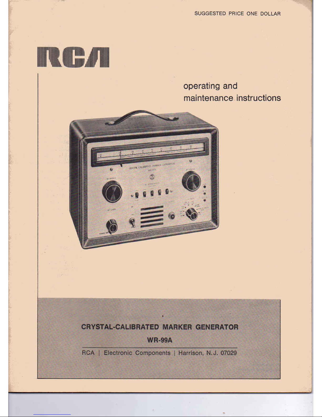
CRYSTAL-CALIBRATED MARKER GENERATOR
WR-99A
RCAIElectronic ComponentsIHarrison, N.J.07029
Page 2
can provide a ground. Working with one hand in your
pocket and standing on a properly insulated floor les-
sens the danger of shock.
2. Filter capacitors may store a charge large enough
to be hazardous. Therefore, discharge filter capacitors
before attaching test leads.
3. Remember that leads with broken insulation pro-
vide the additional hazard of high voltages appearing
at exposed points along the leads. Check test leads for
frayed or broken insulation before working with them.
4. To lessen the danger of accidental shock, discon-
nect test leads immediately after test is completed.
5. Remember that the risk of severe shock is only
one of the possible hazards. Even a minor shock can
place the operator in hazard of more serious risks such
as a bad fall or contact with a source of higher voltage.
6. The experienced operator continuously guards
against injury and does not work on hazardous circuits
unless another person is available to assist in case of
accident.
Safety Praca utions
ITEMS
Supplied
with
WR·99A
The metal case of this instrument is connected to
the ground of the internal circuit. For proper opera-
tion, the ground terminal of the instrument should
always be connected to the ground of the equipment
under test. Therfoutput cable has a shield through.
out its entire length which is connected to the instru-
ment ground and case. It is always best to handle the
cable by the insulation.
An important point to remember is that there is
always danger inherent in testing electrical equipment
which operates at hazardous voltages. Therefore, the
operator should thoroughly familiarize himself with
the equipment under test before working on it, bearing
in mind that high voltages may appear at unexpected
points in defective equipment. Additional precautions
which experience in the industry has shown to' be im-
portant are listed below.
1. It is good practice to remove power before con-
necting test leads to high. voltage points.
If
this is
impractical, be especially careful to avoid accidental
contact with equipment racks and other objects which
I
Output Cable
I
Warranty Registration Card
I
Phone Tip (Red)
1 RCA·6AF4·A
2 RCA-6U8
1 IO-Mc Crystal
1 RCA·12AT7
1 Instruction Booklet
I Phone Tip (black)
1 RCA OA2
2 RCA-6AS6
I RCA-6X4
I 4.S·Mc Crystal
Information furnished by RCA is believed to be accurate and reliable. However, no responsibility is assumed
by RCA for its use; nor for any infringements of patents or other rights of third parties which may result
from its use. No license is granted by implication or otherwise under any patent or patent rights of RCA.
All Rights Reserved
TMK®,Marco Registrada
(4) 3/69
TP·WR·99A
(3)
6/67
Printed in U.S.A.
Page 3
When the generator is set up as a heterodyne-
frequency meter, the frequency of an external signal
may be determined quickly by feeding the signal into
the WR-99A and zero beating it with the
vfo
signal.
The frequency is then read directly from the dial scale.
A slide-switch type of attenuator is used with the
WR-99A to provide attenuation in continuous steps
over a range of 60 db on all frequencies. A special
coaxial cable is provided with the unit for coupling
into the test circuit.
Circuit design and layout provide a flexible system
of modulating therfoutput. For example, when the
WR-99A is used in conj unction with a sweep generator
and an oscilloscope to reproduce a sweep-response
curve, the 4.5-Mc crystal oscillator will modulate the
output from the WR-99A to produce dual markers
spaced exactly 4.5 Mc apart on the curve. With output
set to the frequency of the picture carrier, for example,
the second marker will appear at the point on the
curve corresponding to the sound-carrier frequency.
The vfo signal also may be modulated internally with
both 4.5 Me and 600 cps, a useful feature for adjust-
ment and alignment of sound-if amplifiers and de-
tectors. The 600-cps modulation is also used to produce
a horizontal-bar pattern when the output signal is set
to the frequency of the picture carrier or picture inter-
mediate frequency. The 4.5-Mc output signal may be
modulated with 600 cps for visual alignment of the
detector.
A special socket located at the rear of the WR-99A
permits the connection of an external crystal or L-C
circuit into one of the internal calibrating oscillators.
When an external frequency-determining unit is used
it is possible to produce calibrating beats at intervals
other than 1 or 10 Mc.
The RCA WR-99A is designed for both general
service and production use. The unit measures 10" H
x 13%" W x 7" D and weighs 17 pounds. The
WR-99A is housed in a blue-gray hammeroid case
with a satin-aluminum panel.
Description
The RCA WR-99A Crystal-Calibrated Marker Gen-
erator is designed for use in alignment and trouble-
shooting of black-and-white and color-TV receivers, fm
receivers, and other equipment operating in the fre-
quency range from 19 to 260 Mc. The WR-99A pro-
vides an rf-output signal from 19 to 260 Mc in eight
bands on fundamental frequencies, A wide choice of
modulation facilities is provided, including 4.5 Mc,
which produces dual markers on a sweep-response
curve to mark the picture- and sound-carrier points
on the
curve,
An extremely versatile instrument, the WR-99A
combines the functions of a marker generator, a hori-
zontal bar pattern generator, and a heterodyne-fre-
quency meter. The frequency of the internal variable-
frequency oscillator, as well as the frequency of an
external signal, may be checked with high accuracy
against internally generated calibrating beats at 1- or
10-Mc intervals throughout the tuning range. The
WR-99A includes a harmonic crystal oscillator and a
I-Mc oscillator which is coupled to the 10-Mc crystal
oscillator for accuracy. Both these oscillators may be
switched in or out from the front panel and provide
audio calibrating beats from the speaker in the
WR-99A. Calibration of the WR-99A may be checked
at 242 intervals throughout the tuning
range,
Calibra-
tion of the instrument is straightforward; no charts
are needed.
The tuning dial is specially marked with all vhf
sound- and picture-carrier frequencies as well as im-
portant intermediate frequencies in the 20· to 30-Mc
and 40- to 50-:'\1c regions. In addition, important
color-TV frequencies are also marked on the dial scales.
In
TV servicing, the WR·99A may be used in check.
ing alignment and bandpass characteristics ofrfand
if circuits and the scanning linearity of vertical-de-
flection circuits. The instrument may also be used to
signal trace and trouble-shoot television receivers, and
is useful in locating defective sections and stages.
• 3 •
Page 4
Specifications
Crystal Controlled
hg ~~
Output Voltages:
VFO Ranges " . approx. 0.1 volt rms
Crystal Frequencies .. . approx. 0.05 volt rms
Tonin,.Dial Characteristics:
RF tuning-dial ratio 3.5 to 1
RF
Attenuator:
Range of attenuation 0 to 60 db
Number of steps 12 (5 db each)
Type of attenuator Matched-Impedance Pad
Output.Cable Impedance: 90 ohms
IO·MC Crystal Calibrator:
Accuracy ±0.01%
Number of check points ~..................................... 24
I·MC Calibrator:
Accuracy ± 0.01%
Number of check points 242
4.5·MC Crystal Oscillator:
Accuracy ± 0.02%
Electrical
RF-Oulput Frequencies (fundamentals):
19·28 Mc
27-40 Mc
39·50 Mc
SO·90Mc
75·140 Mc
140-180 Mc
170·220 Mc
20().260 Mc
Internal Modulation:
1 Mc, 10 Mc, 4.5 Mc, 4.5 Mc and 600 cps, 600 cps.
External Modulation:
From external source up to 10 Mc
From plug-infundamental crystal 1 Mc to 30 Mc
From plug-in L-C circuiL. 100 Kc to 10 Mc
Tube Complement:
1 RCA·6AF4A Variable Frequency Oscillator
1 RCA-6AS6 Modulator
1 RCA-6U8 Audio Amplifier
1 RCA·12AT7 10·and I·Mc Oscillator
1RCA·6US 4.5·Mc and 6OO.cpsOscillator
1RCA-6AS6 Mixer
1RCA-6X4 Rectifier
1 RCA·OA2 Voltage Regulator
Power Supply:
Voltage _ 105·125volts
Frequency 50·60 cps.
Power Consumption 45 watts
Mechanical
Hei,ht ~ 10 inches
Width. .. 13lh inches
Depth 7 inches
Weight 171bs.
Finieh Blue-gray hammeroid case, satin-aluminum panel
Functions of Controls
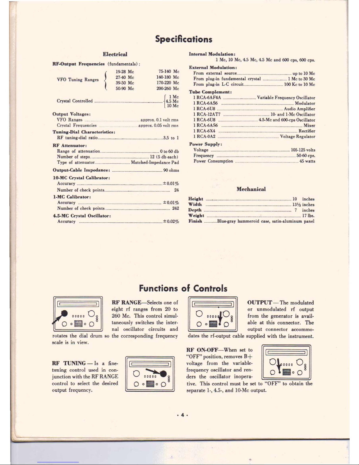
RF RANGE-Selects one of
eight rf ranges from 20 to
260 Mc. This control simul-
taneously switches the inter-
nal oscillator circuits and
rotates the dial drum so the corresponding frequency
scale is in view.
RF TUNING - Is a fine-
tuning control used in con-
junction with the RF
RANGE
control to select the desired
output frequency.
OUTPUT - The modulated
or un modulated rf output
from the generator is avail-
able at this connector. The
output connector
accommo-
dates the
rf-output
cable supplied with the instrument.
RF ON· OFF-When set to
"OFF" position, removes B+
voltage from the variable-
frequency oscillator and reno
ders the oscillator inopera-
tive. This control must be set to "OFF" to obtain the
separate 1.,4.5-, and 10·Mc output.
I
·4·
Page 5
RCA Crystal-Calfbrared Marker Generator WR·99A
o IIt.(O§
0
0:0
0
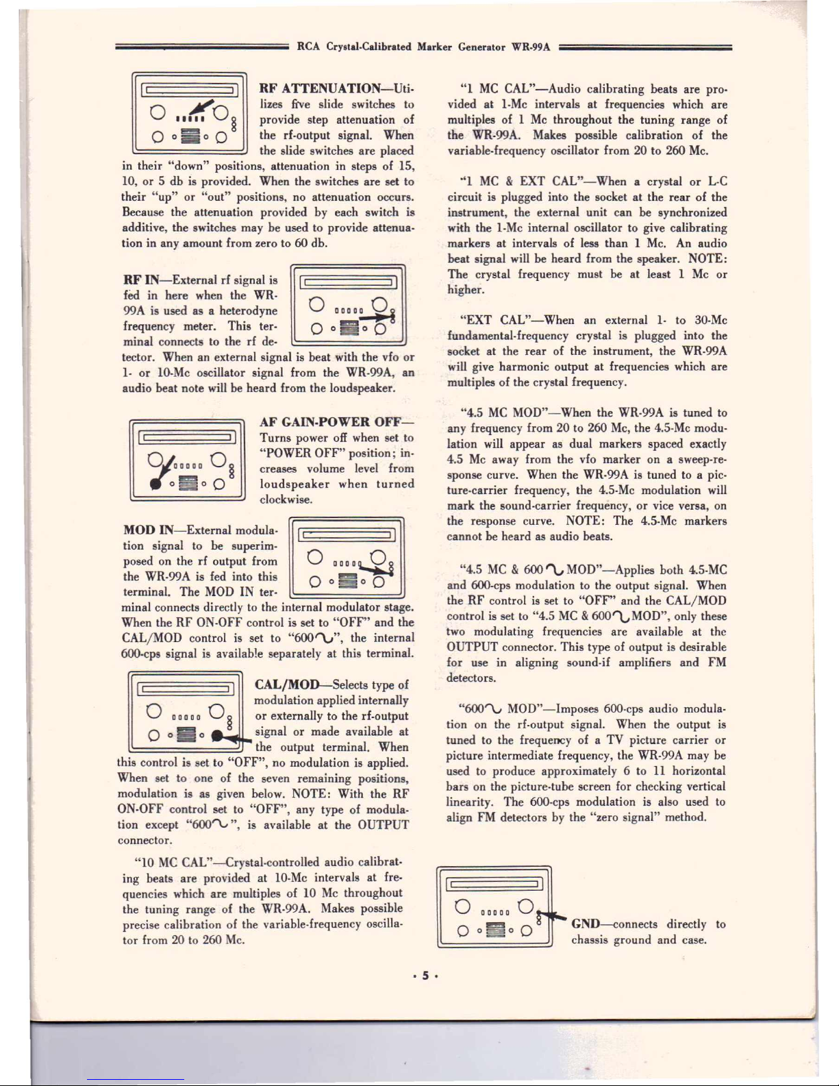
RF ATTENUATION-Uti·
lizes frye slide switches to
provide step attenuation of
the rf-output signal. When
the slide switches are placed
in their "down" positions, attenuation in steps of IS,
10, or S db is provided. When the switches are set to
their "up" or "out" positions, no attenuation occurs.
Because the attenuation provided by each switch is
additive, the switches may be used to provide attenua-
tion in any amount from zero to 60 db.
RF IN-External
rf
signal is
fed in here when the WR·
99A is used as a heterodyne
frequency meter. This ter-
minal connects to therfde-
I
I
tector. When an external signal is beat with the vfo or
1· or IO·Mc oscillator signal from the WR·99A, an
audio beat note will be heard from the loudspeaker.
AF GAIN·POWER OFF-
Turns power off when set to
"POWER OFF" position; in-
creases volume level from
loudspeaker when turned
clockwise.
MOD IN-External modula-
tion signal to be superim-
posed on the rf output from
the WR-99A is fed into this
terminal. The MOD IN ter-
I·
minal connects directly to the internal modulator stage.
When the RF ON-OFF control is set to "OFF" and the
CAL/MOD control is set to "600
"V",
the internal
600·cps signal is available separately at this terminal.
I I
CAL/MOD-Selects type of
modulation applied internally
o
0 00 0 0
0
§
or externally to the rf-output
o
0
E
o._
signal or made available at
t=:======-=-""'=::;r"'"
the output terminal. When
this control is set to "OFF", no modulation is applied.
When set to one of the seven remaining positions,
modulation is as given below. NOTE: With the RF
ON-OFF control set to "OFF", any type of modula-
tion except "600""\.,", is available at the OUTPUT
connector.
"10 MC CAL"-Crystal-controlled audio calibrat-
ing beats are provided at 10-Mc intervals at fre-
quencies which are multiples of 10 Mc throughout
the tuning range of the WR·99A. Makes possible
precise calibration of the variable-frequency oscilla-
tor from 20 to 260 Mc.
·5·
"1 MC CAL"-Audio calibrating beats are pro-
vided at I·Mc intervals at frequencies which are
multiples of 1 Mc throughout the tuning range of
the WR-99A. Makes possible calibration of the
variable-frequency oscillator from 20 to 260 Mc.
"1 MC&EXT CAL"-When a crystal or L-C
circuit is plugged into the socket at the rear of the
instrument, the external unit can be synchronized
with the I-Mc internal oscillator to give calibrating
markers at intervals of less than 1 Mc.
An
audio
beat signal will be heard from the speaker. NOTE:
The crystal frequency must be at least 1 Mc or
higher.
"EXT CAL"-When an external 1- to 30-Mc
fundamental-frequency crystal is plugged into the
socket at the rear of the instrument, the WR-99A
will give harmonic output at frequencies which are
multiples of the crystal frequency.
"4.S MC MOD"-When the WR-99A is tuned to
any frequency from 20 to 260 Mc, the 4.S-Mc modu-
lation will appear as dual markers spaced exactly
4.S Mc away from the vfo marker on a sweep-re-
sponse curve. When the WR-99A is tuned to a pic-
ture-carrier frequency, the 4.S-Mc modulation will
mark the sound-carrier frequency, or vice versa, on
the response curve. NOTE: The 4.S-Mc markers
cannot be heard as audio beats.
"4.S MC&600 '\., MOD"-AppJies both 4.S-MC
and 6OO-cpsmodulation to the output signal. When
the RF control is set to "OFF" and the CAL/MOD
control is set to "4.5 MC&600~MOD", only these
two modulating frequencies are available at the
OUTPUT connector. This type of output is desirable
for use in aligning sound-if amplifiers and FM
detectors.
"6OO'"V MOD"-lmposes 600-cps audio modula-
tion on the rf-output signal. When the output is
tuned to the frequency of a TV picture carrier or
picture intermediate frequency, the WR·99A may be
used to produce approximately 6 to 11 horizontal
bars on the picture-tube screen for checking vertical
linearity. The 600-cps modulation is also used to
align FM detectors by the "zero signal" method.
•I
o
o
0'
t~
GND-connects directly to
chassis ground and case.
00000
O
-
o~o
Page 6
Calibration and Operation
General
Before the WR·99A is put into use, it is important
that the functions of controls and uses of the con-
nectors be understood. The purposes of the controls
and connectors are described under "Functions of
Controls".
This section explains how to calibrate the WR·99A
and how to set up the instrument to provide an un-
modulated marker signal of a desired frequency, or
.a
marker signal which is modulated with one or more
different modulating signals. Some important sugges-
tions are also given for connecting the WR·99A to the
equipment under test and to auxiliary test equipment.
Because the Applications section does not include
instructions for setting up and adjusting the WR·99A,
the user should first make sure he understands the
operation of the instrument before using it in align.
ment applications.
WR·99A Dial Scales
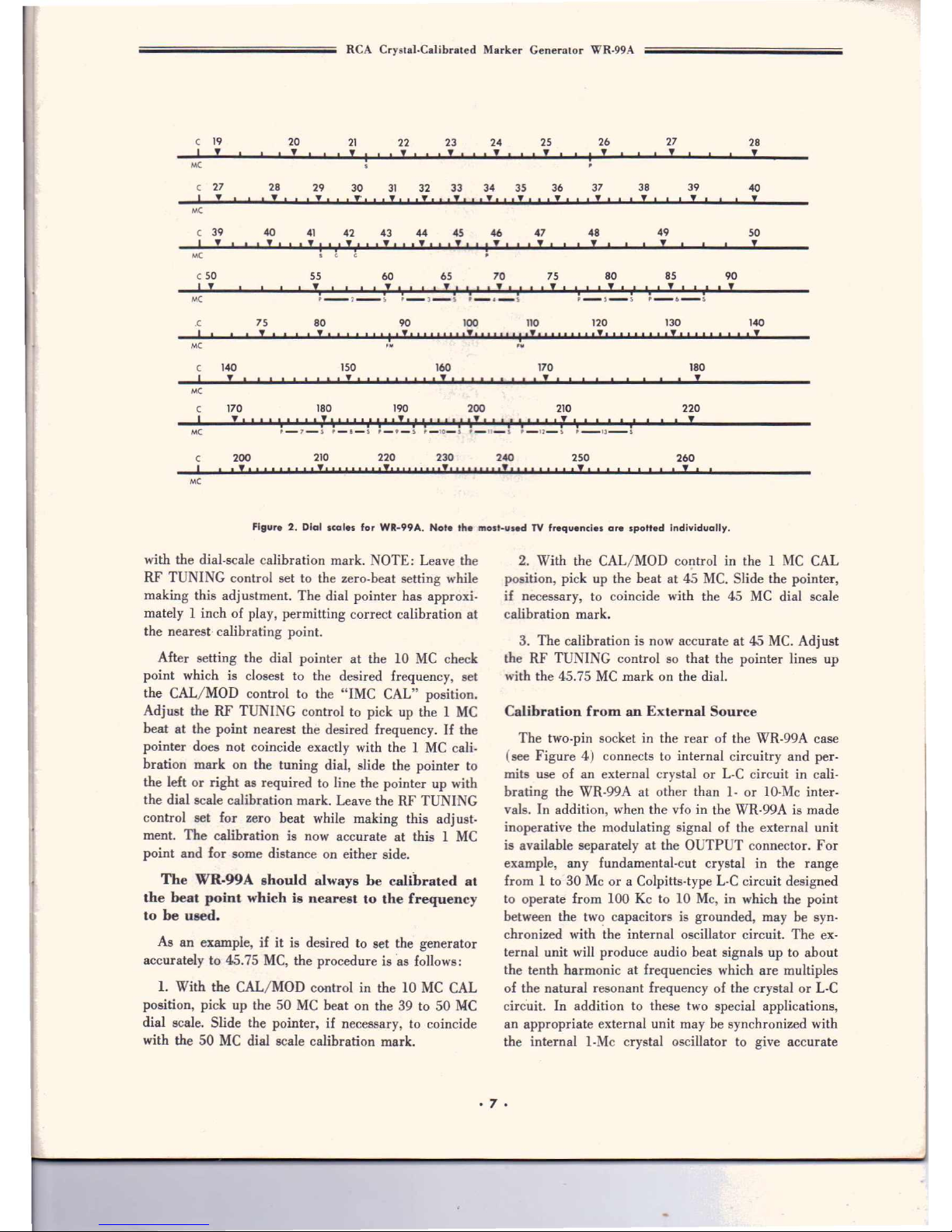
The 20 to 260·Mc tuning range of the WR·99A is
divided into eight convenient tuning ranges (see
Figure 2). The most-used frequencies in the inter-
mediate-frequency and channel- frequency ranges are
spotted individually on the scales. For example, 21.25
and 25.75 Mc are spotted on the first range and -the
intercarrier intermediate frequencies of 41.25 and
45.75 are spotted on the third range. In the TV -carrier
ranges, the picture. and sound-carrier frequencies are
spotted individually to facilitate alignment. All these
frequency settings should be used only after the WR·
99A has been calibrated against the nearest crystal
check point, as described elsewhere in this section.
I
(
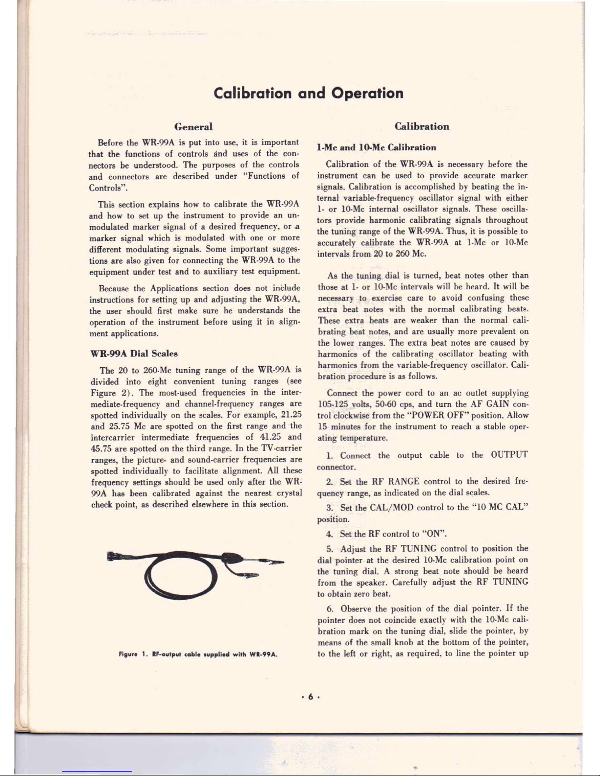
Figure 1. IF· output
cobl.
lupplled with WI-99A.
Calibration
I·Me and IO-Mc Calibration
Calibration of the WR·99A is necessary before the
instrument can be used to provide accurate marker
signals. Calibration is accomplished by beating the
in-
ternal variable- frequency oscillator signal with either
1· or IO·Mc internal oscillator signals. These oscilla-
tors provide harmonic calibrating signals throughout
the tuning range of the WR·99A. Thus, it is possible to
accurately calibrate the WR·99A at I·Mc or lO·Mc
intervals from 20 to 260 Mc.
As
the tuning dial is turned, beat notes other than
those at 1· or 10·Mc intervals will be heard. It will be
necessary to exercise care to avoid confusing these
extra beat notes with the normal calibrating beats.
These extra beats are weaker than the normal cali-
brating beat notes, and are usually more prevalent on
the lower ranges. The extra beat notes are caused by
harmonics of the calibrating oscillator beating with
harmonics from the variable-frequency oscillator. Cali-
bration procedure is as follows.
Connect the power cord to an ac outlet supplying
105·125 volts, 50·60 cps, and tum the AF GAIN con-
trol clockwise from the "POWER OFF" position. Allow
15 minutes for the instrument to reach a stable oper·
ating temperature.
1. Connect the output cable to the OUTPUT
connector.
2. Set the RF RANGE control to the desired fre-
quency range, as indicated on the dial scales.
3. Set the CAL/MOD control to the "10 MC CAL"
position.
4. Set the RF control to "ON".
5. Adjust the RF TUNING control to position the
dial pointer at the desired IO·Mc calibration point on
the tuning dial. A strong beat note should be heard
from the speaker. Carefully adjust the RF TUNING
to obtain zero beat.
6. Observe the position of the dial pointer.
If
the
pointer does not coincide exactly with the IO·Mc cali-
bration mark on the tuning dial, slide the pointer, by
means of the small knob at the bottom of the pointer,
to the left or right, as required, to line the pointer up
• 6 •
Page 7
RCA Cryaral-Cahbrated Marker Generator WR-99A
C
19
20
21 22 23 24
25
26
27
28
I
!
!
I
I ! I !
I
! I I ! !
!
!
~
MC
C
27
28
29
30 31 32 33
34
35
36
37 38 39
40
I
~
I I !
I
I
!I
,!'.
I
I!'
,,!" ,!,,,!" ,!I I
,! ' I!
I
I
!
I!I
!
MC
C
39
40
41 42 43 44 45 46 47 48
49
50
I
! I !I
'!
I
I
i
,! 'I,! '
I
,
..
,
I
,!'
I~
I
!
I
! ! !
i
MC
•
G G
.
c
50 55
60
65 70 75 80 85 90
I
!
!
I
I
I
I!I
I
I I
!
I
I
I I !
I I
I
I ! III ! I
,
I
I
,
I ! I
,
I
!
i i i i i i
MC
.--,--,
;-3-S
'-A._S
P-S-'
P_6_~
.C
I
75
! '
MC
80 90
100
110 120
130 140
I"" "'1'.""""'."""'1'1""""'.""" "' •• ,.",,,
II
150
160
210
C 140
I !
,,',,,!, ,,,,
,,,! '
MC
C
I
170 190
!',,,\',,,
1\' ,,
'I
'I'
,!,
u' ','
I ,
'I
'.1' ,
'I' " , ,,
'1 " ' ,
, !
180
MC
170
,!
180
!
200
220
C
I
200 210
230
P-7_~ P-8-5 '_9_~ '-IO-S
,-n-s
.-I2-S '-13-'
250220
240
260
,! '
,!',,,,,,,,!I , , , , , , ,
'I' ,,,,,I"I' ,,,,,,I'I' ,,,, ,, , ,
!, I
MC
Figure 2_ Dial scale. for WR-99A. N,ote the most-u.ed TV frequenci •• are spotted individually.
with the dial-scale calibration mark. NOTE: Leave the
RF TUNING control set to the zero-beat setting while
making this adjustment. The dial pointer has approxi-
mately 1 inch of play, permitting correct calibration at
the nearest· calibrating point.
After setting the dial pointer at the 10 MC check
point which is closest to the desired frequency, set
the CAL/MOD control to the "IMC CAL" position.
Adjust the RF TUNING control to pick up the 1 MC
beat at the point nearest the desired frequency.Ifthe
pointer does not coincide exactly with the 1 MC cali-
bration mark on the tuning dial, slide the pointer to
the left or right as required to line the pointer up with
the dial scale calibration mark. Leave the RF TUNING
control set for zero beat while making this adjust-
ment. The calibration is now accurate at this 1 MC
point and for some distance on either side.
The WR·99A should always be calibrated at
the beat point whichisnearest to the frequency
toheused.
As an example, if it is desired to set the generator
accurately to 45.75 MC, the procedure is 'as follows:
1. With the CAL/MOD control in the 10 MC CAL
position, pick up the 50 MC beat on the 39 to 50 MC
dial scale. Slide the pointer,ifnecessary, to coincide
with the 50 MC dial scale calibration mark.
2. With the CAL/MOD control in the 1 MC CAL
position, pick up the beat at 45 MC. Slide the pointer,
if necessary, to coincide with the 45 MC dial scale
calibration mark.
3. The calibration is now accurate at 45 MC. Adjust
the RF TUNING control so that the pointer lines up
with the 45.75 MC mark on the dial.
Calibration from an External Source
The two-pin socket in the rear of the WR-99A case
(see Figure 4) connects to internal circuitry and per-
mits use of an external crystal or L-C circuit in cali-
brating the WR·99A at other than 1- or 10·Mc inter-
vals. In addition, when the vfo in the WR-99A is made
inoperative the modulating signal of the external unit
is available separately at the OUTPUT connector. For
example, any fundamental-cut crystal in the range
from 1 to 30 Me or a Colpitts-type L-C circuit designed
to operate from 100 Kc to 10 Mc, in which the point
between the two capacitors is grounded, may be syn-
chronized with the internal oscillator circuit. The ex-
ternal unit will produce audio beat signals up to about
the tenth harmonic at frequencies which are multiples
of the natural resonant frequency of the crystal or L-C
circuit. In addition to these two special applications,
an appropriate external unit may be synchronized with
the internal I-Mc crystal oscillator to give accurate
·7.
Page 8

RCA Crystal-Calibrated Marker Generator WR-99A
calibrating beats at less than I-Mc intervals. Procedure
for using the external feature is as
follower
1.
With power applied to the WR-99A and the out-
put cable connected to the OUTPUT connector, set the
RF
control to "ON".
2.
Set the CAL/MOD control to "EXT CAL". Turn
up theAFGAIN control.
3. Plug a fundamental-cut
1-
to 30;Mc crystal into
the socket at the rear of the instrument case.
4. Tune the
RF
TUNING control and note that
audio-beat signals occur at intervals which are mul-
tiples of the fundamental frequency of the external
crystal, up to about the tenth harmonic.
NOTE:
If
an external Colpitts-type L-C circuit is
connected in place of the crystal, ground the center of
the two capacitors by means of a soldering lug to the
screw adjacent to the crystal socket.
To obtain locked-in calibrating markers at less than
I-Mc intervals, the same procedure used above should
be followed except that the CAL/MOD control is set
to "1 MC&EXT CAL" and an L-C circuit must be
used. The external L-C circuit must be an exact sub-
multiple of 1 Mc to avoid the generation of an exces-
sive number of intermediate beat notes. For example,
an O.25-McL-C circuit can be plugged in and adjusted
by means of a tunable slug in the coil to zero beat with
the I-Mc crystal in the WR-99A to give O.25-Mccheck
points throughout the tuning range of the WR-99A. In
all these applications described above, the external
crystal or L-C circuit will give sideband markers when
the RF control is set to "ON". When the RF control is
set to "OFF", the modulating signal is available sep-
arately at the OUTPUT connector.
--
-
-
---
-
Figure 3. Rear ·iocket-for c~nnection of external crystal or
ColpiHs-type L-C circuit.
Use of 4.5-Mc Sideband Markers
When the WR-99A is set up to deliver an output sig-
nal on either the picture-carrier or sound-carrier fre-
quency of a TV channel, sideband markers which are
spaced exactly 4.5-Mc each side of the vfo marker may
be obtained by setting the CAL/MOD control to the
"4.5 MC MOD" position. For example, if the WR-99A
is tuned to deliver an output signal at the channel 4
picture-carrier frequency of 67.25 Mc and 4.5-Mc
modulation is applied, an additional marker
win
be
observed on the sweep-response
curve.
at the
sound-
carrier frequency of 71.75 Mc. Thi; feature facilitates
checking of bandpass response curves from tuners and
the overall response of both color and black-and-white
TV receivers.
Cottpling the WR-99A to the Test,Circuit
Wherever possible in alignment applications, the
WR-99A should be used with a marker-adder unit,
such as the RCA WR-70A RF/IF /VF Marker Adder.
Test setups which utilize marker-adder units are de-
scribed in the "'Applications" section.
If
the signal
from the WR-99A is coupled directly into the test cir-
cuit, the recommendations which follow should be
observed.
The rf-output cable provided with the WR-99A
should always be used for coupling the instrument to
other equipment. The cable is shielded throughout its
length to prevent excessive radiation of the output
signal and to minimize hum pickup. The output clip
should be connected as closely as possible to the point
of signal injection and the ground clip should be
grounded close to the injection point. When the marker
is fed into the tuner, the ground should be connected
to the tuner shield. Do not connect the output cable to
any circuit containing B+ voltage. Failure to observe
this precaution may result in damage to the WR-99A.
Figure 4. RCA WR-70A Marker Adder.
·8·
Page 9

RCA Crystal.Calibrated Marker Generator WR·99A
When the WR·99A is used to provide a marker for
a high.gain circuit, such as a TV receiver, direct con-
nection of the cable to the injection point may not be
necessary. Often, it is sufficient to lay the output clip
near the injection point, or to connect both clips to the
chassis near the injection point. This arrangement has
the advantage of extremely low circuit loading but has
the disadvantage of possible injection of the signal
into adjacent circuits. For overall alignment, the
marker may be coupled into the receiver by connecting
the output cable directly to the antenna terminals, to
the tuner mixer stage, or to the grid circuit of the first
picture-if stage.
One of the best methods of injecting the signal into
the if strip consists of lifting up the shield on the tuner
mixer tube and clipping the rf-output cable to the tube
shield. The shield should be kept in an elevated po-
sition to prevent shorting the injected signal to ground.
The ground clip should be connected to the tuner
shield. With this method of injection, the marker is
capacitively coupled into the circuit through the ca-
pacitance between the tube shield and the plate of the
mixer tube. It may be necessary to increase the rf
output from the WR·99A when this procedure is used.
The advantage of this method is that circuit loading is
slight compared with direct-coupling methods, and dis-
tortion of the sweep curve is minimized.
Another method consists of clipping directly to the
insulated portion of the grid lead of the mixer stage.
Unless care is taken when this method is used, how-
ever, detuning of the high impedance mixer circuits
may occur and result in a distorted sweep curve and an
erroneous picture of alignment.
In general, the RF OUTPUT attenuator should be
set to give the smallest amount· of output necessary to
obtain a marker of the desired height on the response
curve.Iftoo strong a marker signal is injected into the
circuit under test, it is possible that overloading may
cause distortion of the curve and result in an erroneous
picture of the alignment. The vertical gain control on
the oscilloscope should be set at or near the maximum
gain point so the oscilloscope furnishes a good share of
the signal amplification.
If
this technique is used, the
amount of injected signal can be kept low.
• 9 •
Page 10

Application
General
Eliminating AGe Action
Because the agc voltage in a TV receiver varies in
accordance with the signal fed through the if amplifier
to the agc rectifier, a varying dc voltage is present on
the agc bus. This voltage is applied to the grids of
some or all of the if-amplifier tubes and may also be
fed to the grid of therfamplifier tube.Ifthis voltage
is not rendered inoperative during alignment, difficulty
may be experienced in shaping the response curve, and
final results may be misleading.
This difficulty may be avoided by either disconnect-
ing the age system or rendering it inoperative through
application of an external amount of fixed bias which
is
the same as that provided during normal operation
of the agc system. The RCA WG-307B TV Bias Supply
(See Figure 5) is recommended. This supply furnishes
three output voltages continuously adjustable from 0
to -15 volts, as well as -100 volts (fixed) for use in
color-TV receivers.
If
the RCA WR-69A Television/FM Sweep Genera-
tor is employed in the alignment setup, bias may be
taken from the bias-supply terminals on the generator.
In addition to being a valuable aid during if alignment,
the external bias voltages are highly useful in tracking
down trouble in agc circuits.
Alignment Test Setups
In sweep-frequency alignment, the sweep generator
is tuned to sweep the band of frequencies normally
passed by the wide-band circuits in the TV receiver,
and a trace representing the response characteristics of
the circuits will be displayed on the oscilloscope. The
WR-99A is used to provide calibrated markers along
the response curve for checking the frequency settings
FigureS.RCA WG-307B TV Bias Supply.
of traps, adjustment of capacitors and coils, and for
measuring overall bandwidth of the receiver.
When the marker signal from the WR-99A is coupled
into the test circuit, a vertical "pip" or marker will
appear on the curve. When the WR-99A is tuned to a
frequency within the pass band accepted by the re-
ceiver, the marker will indicate the position of that
frequency on the sweep trace. The technician then
adjusts the circuit components to obtain the desired
waveshape, using the different frequency markers as
check points.
The order in which various sections of the television
receiver should be aligned may differ between different
models of receivers. In all cases, the alignment order
given by the manufacturer in his service notes should
be followed.
Itisnot possible, therefore, to recommend a single
alignment procedure which can be applied with equal
success to all television receivers. Instead, the applica-
tion data given in the following pages are designed for
use in conjunction with the manufacturer's service
notes to aid the technician in aligning a receiver cor-
rectly and efficiently.
Receiver alignment requires, in addition to the
WR-99A Calibrator, a sweep generator having essen-
tially fiat output and good sweep linearity, a cathode-
ray oscilloscope, and a vacuum-tube voltmeter. An
RCA WR-69A or WR-59-series Sweep Generator, an
RCA WO-9lA Oscilloscope, and an RCA VoltOhmyst*,
such as the WV-77E, WV-87B, or WV-98B are recom-
mended. A marker-adder unit, such as the RCA WR-
70A RFIIF/VF Marker Adder, can be used to advan-
tageinthe alignment setup.
Tuner Alignment
To clear up any misconception that a tuner is a
complicated device, consider the tuner when stripped
to its essentials. Except for the switching arrangement
and the usual high and low-pass filters, it is about as
simple as the input of a broadcast receiver. This fact
should be remembered when trouble-shooting problems
arise which are common to all channels. In these cases,
it is good practice to work with the tuner set to only
one channel position until the trouble is corrected.
Afterwards, other channel positions can be compared
·TMK Reg. U.S. Pat. Off.
• 10 •
Page 11

RCA Crystal-Calibrated Marker Generator WR-99A
with the initial one for sensitivity, switching noise,
and general performance.
If
the tuner is satisfactory· in these respects, it is
advisable to check the alignment by observing the
response curves for each channel. Curves for the in-
dividual channels should be examined and compared
with those shown in the manufacturer's service notes.
If
a response-curve check indicates that alignment is
required, the technician should refer to the alignment
curves given in the service notes as guides and follow
closely the recommended alignment procedure.
Alignment should not be attempted until these pre-
liminary tests have been completed. Futhermore, the
technician should be aware that most tuners, unless
tampered with, are correctly aligned. This knowledge
can often prevent misalignment of a good tuner.
The primary purpose of alignment is to obtain a
response curve of proper shape, frequency coverage,
and gain. Most tuners merely require "touch-up"
alignment in which relatively few of the adjustments
are used. Generally, complete over-all alignment is
required only when a person with inadequate knowl-
edge or equipment has worked on the tuner. For a
complete alignment job, it is desirable to follow a
specific sequence of adjustments, the sequence depend-
ing upon the type of tuner. However, where only
touch-up alignment is required, the sequence of adjust-
ment is usually unimportant.
In principle, complete front-end alignment includes
alignment of the antenna input circuits and adjustment
of the amplifier andrfoscillator circuits. The antenna
input circuits are usually aligned to give a response
curve which has a sharp drop-off slightly below channel
2 and which is flat up through channel 13.
In effect, the input circuits, which consist of two or
more traps and high-frequency peaking circuits, act as
a high-pass filter. Their correct alignment is important
in keeping low-frequency interference from entering
the receiver through the tuner circuits. Adjustment of
P 5
Figur.6.Typical tuner curve for channel
8.
the input circuits is usually critical but they seldom
require service.
Alignment of the rf, amplifier and oscillator stages,
however, is a more familiar job. Adjustments include
setting the oscillator. frequencies for channels 2 through
13, setting one or more traps to their correct frequen-
cies, and adjustment of tracking with the rf amplifier.
The converter transformer may also require adjust-
ment along with the tuner.
Al! these adjustments require that a sweep signal
from the sweep generator and a marker signal from
the WR-99A be fed into the tuner so that a response
curve with markers will be reproduced on the oscillo-
scope screen, Alignment is accomplished by setting
adjustments so the waveshape on the oscilloscope
screen resembles the waveshape shown by the manu-
facturer in his service notes. The notes show separate
curves for each of the 12 channels. Each channel is
aligned separately to obtain the desired curve shape.
The marker signals from the WR-99A are USEdto pro-
vide frequency reference points to aid in shaping the
curve.
With the sweep generator set to deliver output on
channel 8, for example, and 4.5-Mc interval markers
injected from the WR-99A at 181.25 and 185.75 Mc,
a typical tuner curve for channel 8 will resemble that
shown in Figure 6. The markers on the curve show
the separation between the picture and sound carriers.
Since the rf sections of the TV receiver must pass both
sound and picture signals, a bandpass of approximately
6 Me is required. The locations of the sound and pic-
ture carrier frequencies for all vhf channels, which are
shown in Table Ilpage] 7' ,are individually marked
on the dial scales.
A necessary preliminary to alignment is a check of
!he test setup. For example, rf bias should be checked
and proper connection points for test equipment deter-
mined. All equipment should be given a 20-minute
warm-up time to enable circuits to stabilize operation.
If
the tuner is to be aligned in the receiver, the tuner
curves should be observed with the first if-amplifier
stage out of operation. Removal of the first if-amplifier
tube is generally sufficient to avoid any curve distortion
caused by the if amplifier. In some tuners, resonance
in the mixer plate circuit may also produce undesirable
reflections. Generally, to remedy this situation, the
picture-if amplifier input must be loaded or the
if-
transformer primary must be detuned.
The tuner oscillator should be in operation during
alignment.
If
it is not, the lack of oscillator injection
voltage at the mixer grid will alter the mixer bias,
.
"
.
Page 12

RCA Crystal-Calibrated Marker Generator WR·99A
resulting in an increase in amplitude of the response
curve and distortion of the waveshape. The oscillator
frequency of intercarrier-type receivers should be
checked by use of the heterodyne. frequency meter
method or the method recommended by the receiver
manufacturer.
Serious misalignment of the tuner or considerable
difficulty or failure in alignment may indicate a defec-
tive component.Ifproper alignment procedure fails to
produce correct tuner curves, the technician should
check individual components in the rf umt.
Over-all Picture-IF Alignment
The general procedure forifalignment of split-sound
and intercarrier types of television receivers is the
same; the major differences being in the number of
intermediate frequencies used and the frequencies. ern-
ployed. As in tuner alignment, the procedure described
in the manufacturer's service notes should be followed
carefully and response waveforms checked against
those shown in the service notes.
If
a television receiver is to give wide-band amplifi-
cation to the television signal, the picture-if system of
the receiver must pass a frequency band approximately
3.5 to 4 Mc wide. This is necessary to insure that all
the video information is fed through to the kinescope
grid and that the resultant picture has full definition.
The bandpass of color TV receivers must be essen-
tially flat to beyond 4 Me to insure that color informa-
tion contained in the color side bands is not lost. Two
special marks are provided on the WR·99A dial to aid
in checking alignment. One mark is placed at 42.17
Mc, the color sub-carrier intermediate frequency. The
other mark is placed at 41.65 Mc, which is the "knee"
or drop-off point on the response curve.
The sweep generator, marker generator, and the
oscilloscope provide the means for determining the
shape of the response curve and the width of the band-
pass. With the equipment set up to obtain a response
curve, the WR·99A is used to check the bandwidth
directly in terms of frequency as follows.
Tune the WR-99A so the marker falls at a point ap-
proximately 70% up the curve slope. Read the Ire-
quency at this point directly from the marker generator
dial scale. Tune the generator so the marker appears
on the opposite side of the bandpass curve at the 70%
response point. The frequency is read from the dial
scale. The difference between the two settings is equal
to the bandwidth of the amplifier.
Two kinds of picture-if systems are generally used
to give the necessary bandwidth. The overcoupled
if
system employes transformers which have their pri-
mary and secondary windings tuned to the same
frequency. The transformers are overcoupled to obtain
a flat-topped response curve of the desired bandwidth.
The other method, the stagger-tuned system, employs
transformers (coils) which are stagger tuned to dif-
ferent frequencies to produce a final over-all if reo
sponse of the desired bandwidth. Some television
receivers employ if systems which utilize both these
principles. It is important, then, that the alignment
instructions given in the service notes be followed
closely.
To obtain an over-all picture-if response curve, con-
nect the direct probe of the oscilloscope across the
second-detector load resistor, which provides a de-
modulated signal to the oscilloscope. Connect the
ground cable to the receiver chassis. Because of the
high degree of signal amplification in the if-amplifier
section, the oscilloscope gain may need to be reduced
to a low level, but not to the point where it is necessary
to use a high level of output from the sweep generator.
An over-all if response curve may be obtained by
feeding theifsweep signal into the amplifier at the
input to the firstifstage or into the mixer stage.Ifthe
markers from the WR·99A are injected into the same
point, intermediate marker frequencies should be used.
Manufacturer's procedure usually calls for stage-by-
stage alignment, starting with the lastifstage and
working forward. Sometimes it may be necessary to
change the sweep oscillator injection point to the grid
of the stage being aligned, or to the plate of the stage
preceding the stage being aligned. This insures that
the response curve is not affected by characteristics of
forward, misaligned stages. As the grid and plate tun-
ing adjustments of .each stage are checked, the fre-
quency of theifmarker is changed accordingly.
Analysis of the Sweep-Response Curve
As
an example of a typical response curve for a TV
receiver is shown in Figure 7. The frequency relation
of the sound carrier to picture carrier is reversed in
the if amplifiers because the .receiver local oscillator
operates at a frequency higher than that of the trans-
mitted carrier. Examination of the waveform will
show that the sound component has been sharply
attenuated.
The following two characteristics of the picture-if
response curve should be noted: (1) the picture-carrier
is set at approximately 50% of maximum response and
• 12 •
Page 13

RCA Crystal-Calibrated Marker Generator WR-99A
Figure 7. Sweep-response curve for picture-if amplifier and de'-
tector. Marker shows picture-carrier frequency.
(2) the sound carrier frequency must be at 1.0% or
less of maximum response. The picture carrier is
placed at approximately 50% of maximum response
because of the nature of single' sideband transmission,
the system used in transmitting television signals.
If
the circuit is adjusted to put the picture carrier too
high on the response curve, the effect will be a general
decrease in picture quality caused by the resulting low-
frequency accentuation; placing the picture carrier too
low on the curve will cause loss of the low-frequency
video response and result in poor definitio~. Loss of
blanking and proper synchronization will also occur.
The skirt selectivity of the picture-if curve is made
sharp enough to reject the sound component of the
composite signal. The sound carrier is kept at a low
level to prevent interference with the video signal. To
achieve this selectivity in split-sound receivers, an
absorption circuit, consisting of a trap tuned to the
sound intermediate frequency, is used. Some receivers
include additional traps tuned to the higher frequency
of the adj acent channel sound carrier. These traps have
a marked effect on the shape of the response curve.
Alignment of traps is described under the headinz
"T ~
rap Alignment".
Checking Response of Individual Stages
The response of individual 'if-amplifier stages or of
two or more stages together may be checked by setting
up the sweep generator and WR-99A as shown in
Figure 8, The sweep signal is fed into the stage im-
mediately preceding the stage being checked, The re-
sponse curve is checked on the oscilloscope, which is
connected across the second-detector load resistor. Be-
fore attempting sweep alignment of the amplifier sec-
tion, the age circuit should be rendered inoperative by
either disconnecting the age bus or by using a bias box,
as described in the section, "Eliminating AGC Action".
Therfcable from the sweep generator is connected
to the grid of the if-amplifier stage ahead of the stage
CRO,
WR-8tA
o
TO
MIXER
o
0
TI
1
OtT
LOAD
RES
Figure 8. Method for checking response of third if-amplifier stage
and detector.
to be checked to isolate the test equipment from the
stage being checked. Therfoutput cable should not be
connected to the grid of the stage being checked be-
cause even slight loading of the high-impedance grid
circuit may cause a change in circuit impedance and
result in distortion of the normal response character-
istic, The marker signal from the WR-99A should be
fed to the grid of the mixer tube.
With equipment set up as shown in Figure 8, a re-
sist-or of small value, such as 470 ohms, should be
connected across the primary of the following if trans-
former. The resistor acts to swamp the primary winding
and prevents inductive reactance of the winding from
affecting the bandpass characteristics of the amplifier
being checked. The shape of the response curve on the
oscilloscope will be determined by the bandpass char-
acteristics of the amplifier stage and the detector
circuits.
If
it is desired to check the bandpass characteristics
of the detector circuit only, the sweep generator output
cable should be moved from point "B" to point "C"
and the swamping resistor, R., placed across the pri-
mary of T4. Response of the second and thirdifampli-
fier stages and the detector stage together may be
checked by moving the rf output cable to point "A"
and connecting the swamping resistor across the pri-
mary of T2.
Trap Alignment
One or more traps may be contained in the rf unit
and picture and sound if amplifiers, depending upon
the type of receiver. Traps are included to attenuate
specific frequencies, such as adjacent picture and sound
carriers, or picture. and sound-if signals in v.ari~us
parts of the receiver.
(Continued on page 18)
. 13·
Page 14

r------------------------------------------------ --- ---- ------- --- ------
I
I
I
I
I
I
I
I
I
i
I
I
I
I
I
I
I
I
I
I
I
I
I
I
I
I
SIF
SIC
SIA
SIB
I
: L------/VI.I\r____J
I RI
: 12
I
~----------------------------------------------------
---------~!-I:l
~ 1500
V5
6AS6
MIXER MOD.
V48
l/z12AT7
1M C OSC
R 39
470
K
R44
f,
330
K
YI
0
'0
MC
C22
R36
3300
R35
470
100
K
K
~:
I. ALL RESISTANCEVALUES ARE IN OHMS EXCEPTt>S NOTED.
2.CAPACITANCEVALUES LESS THAN
1.0
ARE IN UF S 1.0
S ABOVE ARE IN UUF EXCEPT t>S INDICATED.
3.
SWITCHSI B S2 VIEWED FROM FRONT WHEN IN MAX.
COUNTERTERCLOGKWISE POSITION.
4 ALL VOlJAGES MEt>SUREDWITH A·'VOLTOHMYST.'
INDICATED VOLTAGES ARE FOR REFERENCE ONLY
ANO MAY VARY WITH DIFFERENT INSTRUMENTS.
VOLTAGES MEASURED WITIi CONTROLS SET AS FOLLOWS'
51 ON
50'90
MC RANGE.
~~ <?~N':~ MC CAL' POSITION.
S9
.Qtj".
. 14 .
Schematic I
Page 15

ATTENUATOR
r--------------------- ------ -- ----- - ----.,
I ,
i
150B 150B 15DB 100B 5 DB :
: \.~ 0--0 0--0 0--0 0--0 :
I-{
4_7_K
j-J.~~(b:---t+-(1-++-+-i
--<0
\--;~U~-:U~-~U~-6U~~ \>---+l_+n_f-'-.-JRI~,F.(OUT
~OO
J5I~(P2 ~
!
RIO RII RI2 RI3 RI4 I
+
IOOV
ls5g1 .~~
=
i ~
1~1O ~ ,~30 ~
i
C9::r: 39K : R15}> RlliS RI7S RIS R19~ R20~ R21 R22~ R23 «~,~24:
eoo
T IW
!
130'(>1:30? 13d? 130 130>130 ~ 180 ISQ~ 330 <,,30:
CIO ....
I '
1500
T L_ --- -------- - ---- ------1-------------- ----- ----:
i
~'C
AO;" '"""'"
.:lOU'"
I
>'~6
R27 tR2~~ CIS
~t'>
RED~lllkl~~1
V3A
<
470K
MEG
,022 155Vji ~
l/roUlr-~~,OV ~
I
HETERODYNE -~
<> ,/ ~
V ":<.8
OE~;;;:R
l~
r!~
23V ~~
> \
g\'~8 '~~U8
R25> ~
CR2 100<> C 14
~r8
C 16 C17 '
IN34AK ~
0
I 3:30
C 19 R
32
Ie
54
330 K'
t~
>130 10 MFD
1,~47 ~
25 V.
--------.,
I
R4
I
C7..l!5OO
I
I
I
I
I
I
I
I
I
I
I
I
I
I
I
I
I
I
I
I
I
I
I
CI2
I
f-_,
f- - - - -
J
fO------+--+-+-+--'
F
R6
>2700
IW
'>
R7
'>
2700
IW
r
CI3
47
"-55
100
,
,
J2
,
\
.MQll!J
\
=r:
I
\
1
I
J3
,
\
.BE..!ti
.
,
=r=
\
,
I
\
\
,
J4
I
GND
I
I
I
\
I
I
V7
I
EXTERNAL
I
CRYSTALORLC
OA2
'.
I
I
I
I
\
XI
C 20 R 33
4.7
~~c;"
,..----1
vv
58
r
l1~--!{[f.
i
~ sbolsbo):
: L~2_
Ll3):
i : C47 :}:
I II
120
?:
:~~tr::
:---s-----J
PI
3 WIRE POWER CORD
USED ON SOME MODELS
VFO-"ON-OFF"
6.3
7
~
R4Z.
ICQ:r' 560>
C38
QI
S9
.--
.AA
J
R\'2V'I1 ~
2
5DOO
5W
260
t.u
800~
V~
C42A 42 B
3OtJF13OUF
HI
C4t3
7
3300
300 V
V8 .
6X4
~lb
c4o
H9r
75V 210.0 4.5MC
,..-~ [tC41
: -'- \. I 5-25
\
--
\ 1""""1
J
V68
'eV'20V
~6U8
c39 4.5 MC OSC
3300
R51.>
470K>
'Q'RM<
TI
I
2\;
-
~
~""'"
6
?q.;
..._~
~
........
63V
11
[2
12AT7
6l1l
6U8
6X4
6AS6 r~,C44
3300
t
NOT USED IN ALL INSTRUMENTS.
pm of WR-99A
232899-9
. '5 .
Page 16

Replacement Parts List
WR-99A
When ord.rlng r.plocement port" Includ. ,erlol number ond code number of In,trument.
Order ports throullh a local RCA distributor.
Symbol
No.
Description
ClA C1B
CIC ClD
C2
C3
C4 C5
C6
C7toC12
C13
C14
CIS
C16
C17
C18
C19
C20
C21
C22
C23
C24
C25
C26
C27 C28
C29
C30
C31
C32
C33 C34
C35
C36
C37
C38
C39
C40
C41
C42AC42B
C43
C44
C45 C46
C47
C48
C49
C50
C51
C52
C53
C54
C55
CRI CR2
EI
J1
J2 J3
J4
J5
Ll
12
L3
IA
Capocitors
Variable: 4
-sections .
Trimmer: 0.5-5 I'l'f .
Mica: 100 I'l'f ±10%. 500 volts .
Headed lead: 4.7 I'l'f ±20%. 500 volts
Ceramic disc: 3300 I'l'f +100%
-0%.500 volts .
Ceramic: 1500 I'l'f + 100% -0%.
500 volts : ..
Ceramic: 47 1'1'£±20%. 500 volts ...
Ceramic: 330 I'l'f ±20%. 500 volts ..
Ceramic: 15001'1'£ ±20%. 500 volts.
Paper: O.ll'f ±20%. 200 volts .
Ceramic: 3301'1'£ ±20%. 500 volts ..
Paper: 0.0221'£ ±20%. 400 volts .
Paper: 0.47 1'£±20%. 400 volts .
Headed lead: 4.7 I'l'f ±20%. 500
volts .
Trimmer: 0.5-5 1'1'£.. . . . . .. . .
Ceramic disc: 3300 I'l'f +100%
-0%. 500 volts .
Ceramic: 27 I'~ ±10%. 500 volts .
Variable: 5-25 1'1'£ .
Ceramic: 12 I'l'f ±20%. 500 volts .
Ceramic disc: 3300 I'l'f +100%
-0%. 500 volts .
Ceramic: 391'1'£ ±10%. 500 volts .
Ceramic: 120 I'l'f ±20%. 500 volts ..
Ceramic: 100 I'l'f ±10%. 500 volts ..
Ceramic disc: 33001'1'£+ 100% -0%.
500 volts .
Ceramic: 12 I'l'f ±10%. 500 volts .
Ceramic: 3301'1'£ ±20%. 500 volts ..
Paper: 0.11'£ ±20%. 200 volts .
Ceramic: 12 I'l'f ±20%. 500 volts .
Paper: 0.11'£ ±20%. 200 volts .
Ceramic disc: 33001'1'£ + 100%
-0%.500 volts .
Ceramic: 27001'1'£ ±20%. 500 volts.
Variable: 5-25 1'1'£ .
Electrolytic: 30-301'£ + 100%
-10%.350 volts .
CeJamic: 3300 I'l'f +100% -0%.
00 volts .
Ceramic disc: 33001'1'£ + 100%
-0%. 500 volts .
Ceramic disc: 1500 I'l'f + 100%
-0%. 500 volts .
Ceramic: 1201'1'£ ±20%. 500 volts ..
Variable: 3-121'1'£ .
Ceramic: 5.6 1'1'£± 1.0 I'l'f. 500 volts.
Variable: 3-12 1'1'£ .
Ceramic: 5.6 I'l'f ±LO 1'1'£.500 volts.
Variable: 5-25 I'l'f .
Ceramic: 47 1'1'£±10%. 500 volts .
Electrolytic: 10 I'f. 25 volts .
Ceramic disc: .01
}if.
500 volts .
******
Resistors
Stock
No.
Stock
No.
Description
214763
• 16 •
214767
213732
76373
70392
31048
48982
502012
502222
502410
502347
502147
512227
512339
502410
502127
33571
502056
33571
502118
502133
502410
502447
502522
214790
522312
33571
502127
502410
502447
502347
Crystal: type IN34-A .
Post. binding .
Connector:
RF
Output .
Jack: ModInand RF
In .
Jack: single contact .
Connector .
Inductor. adjustable .
Inductor, adjustable .
Inductor, adjustable .
Inductor, adjustable .
502447
502410
512333
Symbol
No.
L5
L6toL9
LIO
Lll
LSI
PI
P2
P501
Inductor. adjustable .
Inductor .
Inductor, adj ustable .
Reactor. filter: 13.35
H .
Speaker: 3" P::\l
type .
Cord.
power:
78" long. with plug .
Connector: for attenuator .
Connector:
coaxial-type,
for
RF
cable .
502456
503433
214769
93463
103856
102235
213734
214789
75609
75792
75610
73784
75792
73562
78977
102235
93463
213734
205918
204811
94228
213734
75450
76347
214787
213734
214792
75792
Rl Composition: 12 ohms ±10%.
}1
watt .
R2 Composition: 2200 ohms ±10%.
Y2
watt .
R3 Composition: 100.000 ohms ±10%.
Y2
watt .
R4 Composition: 47.000 ohms ±10%.
Y2
watt .
R5 Composition: 470 ohms ±10%.
}1
watt .
R6 R7 Composition: 2700 ohms ±10%. 1
watt .
R8 Composition: 39,000 ohms ±10%.
1
watt .
R9 Composition: 100,000 ohms ± 10%,
Y2
watt. .
RIOtoR12 Composition: 270 ohms ±10%.
}1
R13
I
Co":n~ti~~~·
i30'~h~~'·±5·%·. ~.
watt .
R14 Composition: 56 ohms ±10%,
}1
watt .
R15toruo Composition: 130 ohms ±5%.
Y2
watt .
R21 R22 Composition: 180ohms ±10%.
}1
watt .
R23 R24 Composition: 330 ohms ±10%.
Y2
R25
I
Co':~iJ.~~·:
·ioo.ooo
'~h~{s'
±
iO%: .
Y2
watt .
R26 R27IComposition: 470.000 ohms ± 10%.
:Y2
watt .
ru8 Composition: 2.2 meg ±10.Y2watt.
ru9 Variable: 0.5 meg ±20%. ~ watt
(includes 89) .
R30 R31 Composition: 12.000 ohms ±10%. 2
watt .
R32 Composition: 130ohms ±5%.
Yz
watt .
R33 Composition: 270 ohms ±10%.
Yz
watt .
R35 Composition: 100.000 ohms ±%10.
Yz
watt .
R36 Composition: 470.000 ohms ±10%.
Yz
watt .
R3i Composition: 47.000 ohms ±10%.
}1
watt .
R38 R3.l) Composition: 470.000 ohms ±10%.
Y2
watt .
R40 Composition: 100.000 ohms ±10%.
Yz
watt ~ .
R41 Composition: 33.000 ohms ±10%. 1
R42 Co':;'~iiio~':
·iio.ooO·ohl~;s·
±iO%:'
Yz
watt .
R43 Composition: 560.000 ohms ±10%.
Yz
watt .
R44 R45 Composition: 330.000 ohms ±IO%.
}1
watt , .
73784
94228
73784
213734
214791
204811
214788
213734
213734
73748
76347
56231
74182
56231
74182
204811
77531
59395
2.12151
96257
214783
214782
51388
214766
214765
214764
214764
Page 17

Symbol
No.
R46
R4i
R48
R49
R50
R51
R52
R53
R54
R55
R50l
81
82
S3 to 87
88
S9
Tl
T2
Xl
Yl
Y2
Delcription
Composition: 210.000 ohms ± 10%.
~ watt .
Composition: 560 ohms ±10%. ~
watt .
Composition: 68.000 ohms ± 10%,
~ watt .
Composition: 220,000 ohms ±10%,
Y2
watt .
Composition: 100,000 ohms ±10%,
~ watt .
Composition: 470.000 ohms ±10%,
Y2
watt .
Wire Wound: 5000 ohms ±20%,
5 watt .
Composition: 12 ohms ±10%.
~ watt .
Composition: 270 ohms ±10%.
~ watt .
Composition: 100 ohms ±10%,
~ watt _ .
CORrc~~\~).:
.9.1~~~~'. ~
.~a~~?~r..
••••••
Siock
No.
Symbol
No.
502427
502156
502368
502422
502410
502447
205065
502012
502127
47452
214798
214770
214469
214760
214793
37806
214781
214795
214796
D.lcriptlon
Milc.llon.oul
Bezel: polystyrene, silver .
Cable, rf-output: complete .
Capacitor: ceramic-disc, 10.000
jl.jI.f
+100%, -0%,500 volts .
Clip alligator: for rf cable .
Foot, rubber: for carrying case .
Handle, carrying .
Insulator: black, for alligator clip .
Insulator: red. for alligator clip .
Knob, control: 1~6'" dia, blue .
Knob. control:
134'" dia,
with pointer,
blue .
Knob. control:
134'"
dia, blue .
Lamp: 6.3 volts .
Pointer assembly: complete with
slider, slider spring, pointer handle,
and pointer .
Pulley. dual: I'" O. D.X1~6'" long ..
Pulley, single:
34'"
x 1.5'" dia .
Pulley; drive: for tuning shaft, 2'"dis
x
1.4'" wide .
Pulley. single:
34'"
thick
x
2Ys
M
dia ..
Pulley, single: ~6'" thick x 3~" dia ..
Pulley. single:
%4'"
thick x
Ys
M
dia,
aluminum .
Pulley, single: ~ .. thick x ~'" dia,
aluminum : .
Scale. dial: calibrated .
Shell: for rf cable. match pair .
Socket. tube: 7-pin .
Socket, tube: 9-pin .
Socket, pilot lamp .
Spring. coil: 0.156'" dia x
U6
M
long .
Spring, coil: 0.185'" dia x I'" long .
Stud: for carrying handle .
Window: for dial .
Stock
No.
214785
214797
73960
35262
211887
212102
99539
204879
212148
214778
214779
11891
214772
214777
214776
204480
214775
214774
214761
214762
214768
47452
204899
204900
214780
214784
214771
214786
214773
Switch. rotary: 4 sections. 8 positions.
12 circuits .
Switch,
rl_ltary: 2 sections. 8 positions
5 circuits .
'Switch, slide: DPDT, 0.5 amp, 125
volts .
Switch, toggle: SPST, 6 amps. 125
volts; 3 amps. 250 volts .
(Part of R 29)
Transformer, power .
Transformer, audio output .
Socket, crystal .
Crystal: 10 Mc .
Crystal: 4.5 Mc .
TABLE I
Chonn.1 Chonn.1
l'ictvr...cafTl.r Soun"-c .... I.r
No. Fr.... IMel Fre... IMeI. Fr.... IMeI
t
2
54-60
55.25
59.75
3 60·66
61.25 65.75
4
66·72
67.25
71.75
5
76-82 77.25
81.75
6 82·88 83.25
87.75
7 174·180
175.25 179.75
8 180-186 181.25 185.75
9 186·192 187.25 191.75
10 192·198 193.25 197.75
11 198·204 199.25 203.75
12 204·210 205.25 209.75
13 210·216 211.25 215.75
.Value. given in thi. colum,Dare ideDtified on. dial
le.Ie
al
"2P''.
u3P". etc.
tV.luel
liveninthi.
column are
identified
on di.al
Kale ••
"2S", 0.35",
etc.
17 •
Page 18

RCA Crystal. Calibrated Marker Generator WR·99A
SCOPE
M~RKER
GENER~TOR
WR-b4A
LOW-C~P~CITANcE
PROBE HERE
INTERMEDIATE
__.-o'IJ\
rREQUENCY
MARKER
o
o
0
SOUND
TR~NS
FM
DETECTOR
Figure 9. Test-equipment setup for alignment of sound-if
ClIlpJilier.
The test-equipment setup for alignment of traps in
theifamplifier is the same as that used in conventional
if
alignment described above. A sweep·response curve
is obtained on the oscilloscope screen, and a marker
from the WR·99A, which is set to the frequency of the
trap, is fed into the mixer stage.
Because the response of the amplifier is very low at
the trap frequencies, the marker may often be difficult
to see on the response curve. The use of a marker-
adder unit, such as the RCA WR-70A RF /IF /VF
Marker Adder is recommended for trap alignment. The
unit is especially valuable in trap-alignment applica-
tions because the marker is added to the response
curve
after
the sweep signal is taken out of the receiver,
thus eliminating all suckout.Ifa marker adder is not
used, the WR·99A should be set for maximum output
and the scope gain set to maximum to increase the size of
the marker.
If
difficulty is experienced, more precise
adjustment may be achieved by connecting a Volt-
Ohmyst, set for de-voltage measurements, across the
second-detector load resistor, and tuning the trap for
minimum voltage reading on the meter.
The general procedure in aligning picture-if ampli-
fiers is first to set the traps and then to align the am-
plifier circuits. Since any adjustment of the amplifier
circuits usually will slightly detune the traps, the traps
may have to be "touched up" during the picture-if am-
plifier alignment. The manufacturer's alignment in-
structions will again determine the exact procedure to
follow.
Alignment of Sound-If' Amplifiers and
FM
Detectors
A typical test set-up for aligning an intercarrier-type
sound-if amplifierisshown in Figure 9. This system
employs a ratio detector which reeei..es its signal di-
rectly from the
last
sound-if amplifier stage. Circuits
which use a discriminator detector will employ a lim-
iter stage ahead of the detector circuit.
An
over-all response curve of the sound-if amplifier
and detector is ohtained
by
connecting the sweep gen·
erator and the "\\R·99A at point "A", the grid of the
first sound-if amplifier. Set the CAL/MOD control on
the WR·99:\ to "4.5 :\-IC". The oscilloscope is con-
nected at point "C", where a demodulated signal ap·
pears. The sweep width control on the sweep generator
shouldbeset to ~ve a sweep width of approximately
1 Me.
An "S'vshaped
curve, similar to the curve shown
in Figure 10. will appear on the oscilloscope screen.
To check alignment of the first if-amplifier stage
only, the oscilloscope probe should be moved to point
"B" where a sweep response curve similar to that
shown in Figure 11 should be obtained. The marker
indicates the 4.5·Mc center frequency of the curve.
If
the marker does not appear exactly at the center of the
curve, the amplifier should be adjusted as recom-
mended by the manufacturer until the marker is
exactly at the center of the curve. This assures that re-
sponse is symmetrical and adequate audio bandwidth
is obtained.
• 18 •
Page 19

RCA Crystal-Cal ibrated Marker Generator WR·99A
Figure 10. Response curve for fm-sound detector. Symmetrical Figure 12. FM-detector curve showing 600-cps modulation. Mod-
shape indicates correct alignment. ulation causes wide trace or waviness on base line. When center
frequency of detector is tuned exactly to the sound intermediate
frequency, modulation will disappear.
Figure 11. Sound-if response curve. Marker shows center of pass
band and is the sound intermediate frequency.
If
a discriminator detector is used, the stage will be
preceded by a limiter. The over-all response of the if
amplifier is checked by connecting the oscilloscope
across the resistor in the grid circuit of the limiter, In
some receivers, the time constant of the grid circuit
may be large enough to cause distortion of the pattern
when the scope is connected.Ifthe pattern is distorted,
the difficulty may be eliminated by temporarily remov-
ing the capacitor from the rf circuit or by shunting the
resistor with another resistor of a value determined by
experimentation.
The response of the sound-if amplifier alone in a
system using a discriminator-type detector may be
checked by using the same procedure as for checking
an amplifier using a ratio- type detector. Set the CALI
MOD control to "4.5 Mc&600 CPS". The sound-if
point should appear at the intersection of the response
curve and the zero-reference line. Tune the detector
transformer as indicated in the manufacturer's service
notes.
If
the detector is not correctly aligned, the 600 cps
will
modulate the "S" curve, as shown in Figure 12.
When the detector is set to exactly 4.5 Mc, the modula-
tion will be cancelled out.
Use of WR·99A as Heterodyne Frequency
Meter
The WR-99A may be used with good accuracy to de-
termine the frequency of an external signal between
20 and 260 Mc. In general, the procedure consists of
feeding the signal of unknown frequency into the
WR-99A, mixing it with the vfo signal from the WR-
99A, and, by use of the zero-beat method and inter-
polation, reading the frequency directly from the WR-
99A dial. This feature is particularly useful in checking
the oscillator frequency in intercarrier receivers. Pro-
cedure is as follows:
1.
Connect a lead from therfoutput of the external
signal source to the RF IN connector.
2. Set the tuning dial of the WR-99A to read the
approximate estimated frequency of the external signal.
3_ Calibrate the WR·99A at the I-Mc or 10-Mc
check point nearest the frequency of the external sig-
nal, as described under "Calibration".
4.Ifthe unknown signal is of very low level, turn
the AF GAIN control fully clockwise. It may also be
necessary to connect a ground lead from the external
signal source to the GND terminal of the WR-99A.
5. Turn the tuning dial of the WR·99A until zero
beat is obtained with the external signal.
6. Determine the frequency of zero beat by observ-
ing the dial setting and interpolating, as described un·
der "Calibration".
• 19 .
Page 20

Maintenance
Figure 13. Block diagram of WR-99A .
Caution:
See
"Safety Precautions", Page 2
~neral
Performance of the WR-99A depends upon the
qnality of the components employed.Ifit should be
necessary to replace any of the component parts, only
Rc..~ replacement parts or equivalents of those shown
:=:
the Replacement Parts List of this instruction book-
ott
should be used.
The chassis may be removed from the case by re-
moring two screws from the bottom of the front bezel,
removing the bezel by sliding it off the bottom and
lifting upward, removing two screws from the back
of the case, and removing 14 screws from around the
edge of the front panel. Pull the panel and chassis
out of the case.
If
any alignment adjustments are made, the line
yol.tage should be 117 volts, at 60 cps.Iftrouble is
encountered, voltage readings should be taken and
compared with the operating voltages shown on the
schematic diagram. Conventional trouble-shooting tech-
niques should be used to locate trouble.
p
=
rRONT PANtl..
/>OJ
Circuit Desceiption and Operation
The WR-99A is built around a Colpitts-type variable-
frequency oscillator (VI) which utilizes an RCA-
6AF4-A. (See Figure
13).
This oscillator is tunable by
means of capacitor sections CIA, CIB, CIC, and CID
over a band of frequencies from 20 to 260 Mc. This
band is divided into eight overlapping
rf
ranges. On
ranges 1 through 5, capacitor sections CIC and CID
and sections CIA and CIB are paralleled. On ranges 6,
7, and 8, only sections CIB and CIC ar-e used.
Output from VI is taken from the grid and fed to
the grid of the modulator stage, V2. Any internal or
external modulation is mixed with therfsignal in this
stage. Output from the V2 modulator stage is fed
through capacitor C6 to the attenuator network.
Internal crystal-controlled calibrating markers are
generated by a Miller-type crystal oscillator stage,
V4A, which generates lO·Mc harmonic signals. One-
megacycle calibrating markers are generated by a
I-Mc Colpitts oscillator, V4B, which is locked to the
V4A osciUator in a lO·to-l ratio. These oscillators may
be switched out of operation from the front panel.
. 20 .
Page 21

RCA Crystal-Calibrated Marker Generator WR-99A
The 10- and I-Me signals from V4A and V4B are
fed to the mixer/modulator stage, V5, which mixes
the two signals and feeds them through CI3 and C5 to
grid No. 1 of V2. The output from V5 also contains
harmonics of the two signals. The 4.5-Mc signal is
generated by V6B, a Pierce oscillator. The 4.5-Mc is
fed through C37 to grid No. 3 of V2. The 6OO-cps
modulating signal is generated by a phase-shift oscil-
lator, V6A, which feeds the signal to grid No. 3 of
V2. Any signal fed into the MOD IN terminal is also
fed to grid No.3 of V2.
Crystal diodes CRI and CR2 comprise a voltage-
doubler beat-frequency detector. In this circuit, the
I-Mc, IO-Mc, or external signals are beat with the vfo
signal from VI to produce an audio-beat signal from
the speaker. V3A and V3B are audio-frequency ampli-
fiers.
Regulation of the B+ voltage for the vfo stage, VI,
is accomplished by use of OA2 regulator tube, V7.
IO·Mc Crystel-Oscllfatcr Adjustment
1.
Connect the WR-99A to a 1- and 10-Mc standard
oscillator, as shown in Figure 15. A Measurements
model III or equivalent unit may be used as the
standard.
2. Set the RF control on the WR-99A to "OFF". Set
the CAL/MOD control to "10 MC CAL". Turn the AF
GAIN control about three-quarters turn clockwise. Set
the standard oscillator to deliver a 10-Mc output signal.
3. With an insulated alignment tool, turn the slug
in inductor L9 until about one-quarter inch protrudes
from the coil form. (See Figure 14 for locations of in-
ternal adjustments.]
4. Screw the core slowly back into the coil form and
listen for an audio beat between the two 10-Mc signals.
Continue screwing in the core until the beat note disap-
pears; then, back the core out of the form one full
turn. Switch the CAL/MOD control between "10 MC
CAL" and "OFF" several times to make sure that the
WR-99A 10-Mc oscillator starts promptly.1£oscillator
starts erratically, back out the cere until oscillation is
satisfactory.
S. Adjust trimmer capacitor C24 to zero beat the
two 100Mc signals as closely as possible.
I·Mc Oscillator Adjustment
1.
With power applied to the WR-99A, set the RF
control to "ON". Set the RF RANGE switch to band 2
(27-30 Mc).
2. Set the CAL/MOD control to "10 MC CAL" and
set the RF TUNING to read 30 Mc on the dial scale.
With an insulated alignment tool, adjust the core of
L2 to zero beat with the third harmonic of the 10-Mc
crystal oscillator. Check the zero-beat accuracy at the
4O-Mc point. Readjust L2, if necessary.
Figur.
14.
Locations of tub .. and internal adlustments in
WR-99A •
. 21 •
Page 22

RCA CrY8tal.Calibrated Marker Generator WR·99A
lOMe:
STAHMRD
OSCILLATOR
1 @-+-I
---+~
11
Fiture 15. Test setup for alignment of 10-Mc oscillator.
WR-99A
IIo4AAKCA
ADDEA
Ar
OUT
Q
CAO
IWe
STANDAAD
0
OSCILLATOA
Ar
OUT
0-
,__
VCA"!:
Figure 16. Tesl setup for alignment of l-Mc oscillator.
4. Set the RF control to "ON" and carefully check
between the 30. and 4O·Mc points for a strong beat at
each I·Mc dial mark.Ifthe check points are at other
than
I·Mc intervals, adjust LlO to the next lock-in
point, higher or lower as required, to give the required
sub-multiple of 10 Me.
5. Adjust the core of LI0 and observe the adjust.
ment range over which correct look-in occurs: Reset
the core to the center of the lock-in range.
4.5-Mc Oscillator Adjustment
Alignment of the 4.5·Mc oscillator requires,
in
ad-
dition to the WR:99A, a cathode-ray oscilloscope, such
as the RCA WO-91A, a I·Mc standard oscillator, such
as
the Measurements model
Ill,
and a marker-adder
unit, such as the RCA WR-70A RF /IF/VF Marker
Adder.
1. Connect the equipment as shown in the test setup
of
figure
16.
2. With power applied to all units, set the CAL/
MOD control on the WR-99A to "4.5 MC MOD". Set
all
attenuator switches to "OUT" and set.the RF con-
trol to "OFF"
3. Adjust the amplitude controls on the market-
adder unit to observe the beat on the oscilloscope
screen between the second harmonic (9 MC) of the
4.5-Mc oscillator in the WR-99A and the ninth har-
monic from the I-Mc standard oscillator.
WA-99A
SWEEP
(;'[NEAATOA
STANDAAD
SIGNAL.
(;.[NEAATOA
Ar
Ar
Ar
OUT
OUT
9
OUT (
T
CRO
WAAKEA
0
ADDEA
'--
~9
VCAT.
I
Figure 17. r.st selup for vfo tracking adiustments.
4. Adjust trimmer capacitor C41 to obtain as close
zero beat as possible.
VFO Tracking Adjustments
NOTE: All vio adjustments must be made in the
order listed.
Band 7 Adjustments. Alignment of the variable-
frequency oscillator requires,
in
addition to the WR-
99A, a sweep generator, such as the RCA WR·69A or
a WR-59-series unit, a marker-adder, such as the RCA
WR-70A RF/IF /VF Marker-Adder, an oscilloscope
such as the RCA WO-9IA, and a standard signal
generator which can deliver output in the vhf region,
such as a Measurements model 80.
1.
Connect the instruments as shown in the test setup
of
Figure 17.
2. Set the RF RANGE control to band 7 (170 to
220 Me).
3. Adj ust the sweep generator to deliver output on
channel 8. Set the standard signal generator and the
WR·99A to deliver output at 170 Me. Adjust the con-
trols on the marker-adder and the oscilloscope to ob-
tain two markers on the oscilloscope sweep trace.
4. Adjust the high-frequency trimmer, C2, in the
WR-99A to approximately the center of its range.
Ad-
just inductor
L 7
until the two markers coincide on the
trace.
5. Tune the WR·99A and the standard signal gen-
erator to 220 Me. Set the sweep generator to deliver
output on channel lit.
6. Readjust C2 in the WR-99A to again coincide the
markers on the scope trace.
7. Repeat steps 4, 5, and 6, as necessary, until both
ends of the band-7 frequencies track correctly.
8. Decrease the output from the standard signal gen-
erator and the sweep generator. Set the CAL/MOD
control to "10 MC CAL". Recheck tracking at the 10·
Me points on band 7 and readjust, if necessary .
. 22 .
Page 23

RCA Crystel-Caltbreted Marker Generator WR·99A
Figure 18. Dial-Stringing arrangement in WR-99A.
Band 4 Adjustments - The test setups and tech-
niques for alignment of band 4 are the same as de-
scribed above, except as follows;
1. Set the sweep generator to deliver output on
channel 2; adjust the standard signal generator and
the WR·99A to deliver output at 50 Mc.
2. Adjust trimmer C21 to approximately center
range; adjust inductor
fA
to coincide the two markers
on the oscilloscope trace.
3. Tune the standard generator and the WR·99A to
90 Mc. Set the sweep generator to deliver output on
channel 6. Readjust C21 to again coincide the markers.
4. Repeat steps 2 and 3 until both ends of band 4
track correctly.
5. Recheck tracking at 10·Mc crystal check points
and readjust,ifnecessary.
Band 1 Adjustments -- The test setup and techniques
for alignment of band 1 are the same as described
above except as follows.
1. Tune the standard generator and the WR·99A to
19 Mc. Turn off the sweep generator.
2. Adjust capacitor C48 to approximately one-half
CENTER SCALE IN
WINDOW ....ND SET
SWITCH IN
1ooIAX.
CLOCK-
WiSt POSITION ....ND
STRING AS SHOWN.
Rr RANGE
capacity and adjust the core of Ll until a beat appears
on the oscilloscope trace.
3. Tune the standard generator and the WR-99A to
28 Mc. Adjust C48 for zero beat of the two signals.
4. Repeat the low- and high-end adjustments until
both the 20- and 28-Mc points track perfectly.
5. Reduce output from the standard generator. Set
the CAL/MOD control to "1 MC CAL" and check the
tracking at all I-Mc calibration points from 19 to 28
Mc. Readjust, if necessary, to obtain correct tracking.
Band 2 Adjustments - Utilize the same procedure
described under "Band 1 Adjustments" except align
the low-frequency end by means of L2 at 25 Mc. Align
the high-frequency end at 40 Mc by means of C50.
Adjustments lor Other Bands - Utilize the same
procedure described under "Band 1 Adjustments" ex·
cept as follows:
Band 3 - Adjust L3 at 39 Mc; adjust C52 at 50 Mc.
Band 5 -Adjust L5 at 80 Me only.
Band 6 - Adjust L6 at 140 Me only.
Band 8 - Adjust L7 at 210 Mc only.
GUIDE ROD TO BE: POSITIONED
7
EQUIDISTANT FRO'" IDLERS AT
tiTHER ENDorTR....VEL.
I
"'-'
....
'
NOTt: !tTRINC. DIAL WITH RF TUNING
C....P....CITOR IN "'AX. COUNTtR-
CLOCKWISE POSITION.
4
V
2
TURNS
·23 .
Page 24

RCA Crystal-Calibrated Marker Generator WR-99A
·24 .
RCA Repair Service
RCA maintains a complete repair service for the
adjustment, calibration, and maintenance of RCA
test equipment.
If
it becomes necessary to service
this equipment, the report forms enclosed in this
booklet should be filled out as described. It is
important that:
1.
Test equipment be packed carefully.
2. A full description of the trouble be included
in the report.
3. All probes, cables, and test leads used with
the equipment be included in the shipment.
Attention to these details
will
help prevent
damage in transit and delay in
repairs,
Page 25

Page 26

.$••
nOli
 Loading...