

Page 1
Model:RLDED3230A-RR
Page 2
Page 3
Page 4
*
SAFETY PRECAUTION
CAUTION
•
•
•
WARNING:
PLACEMENT INFORMATION
SAFET Y INFORMATION
RATING PL ATE LOCATION
FCC STATEMENTS
WARNING:
1
CAUT ION M ARK ING W AS LO CAT ED AT THE REAR
OF THE A PPA RAT US.
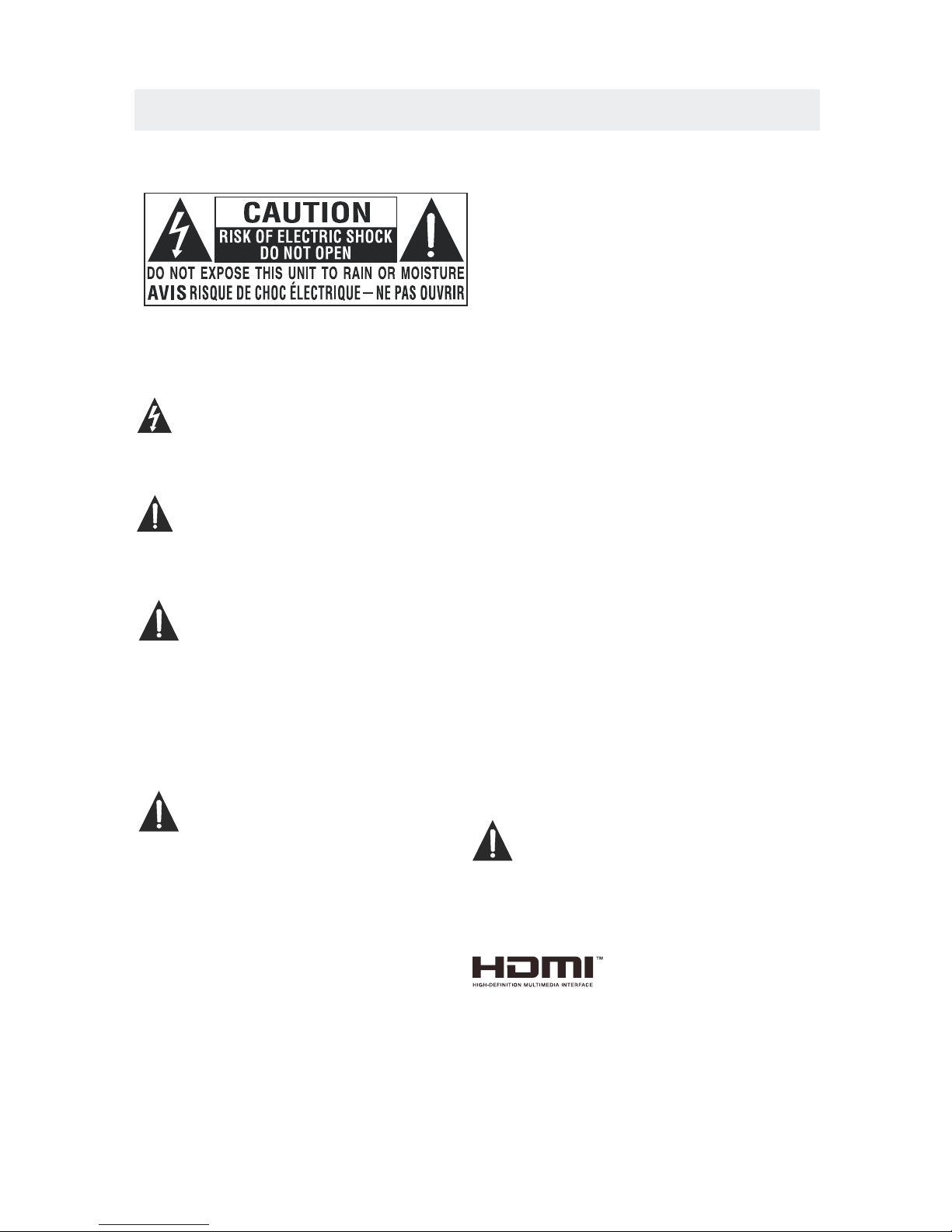
WARNING: TO REDUCE THE RISK OF ELECTRIC
SHOCK,DO NOT REMOVE COVER(OR BACK)
NO USER SERVICEABLE PARTS INSIDE.
REFER SERVICING TO QUALIFIED SERVICE
PERSONNEL.
The lightning flash with arrowhead symbol,
within an equilateral triangle,is intended to
alert the user to the presence of uninsulated
“dangerous voltage”within the product's enclosure
that may beof sufficient magnitude to constitute a
risk of electric shock to persons.
The exclamation point within an equilateral
Triangle is intended to alert the user to
The presence of important operating and
maintenance (servicing) instructions in the literature
accompanying the appliance.
DANG ER OF E XPL OSI ON IF B ATTERY IS
INCO RRE CTL Y REP LAC ED. REPLAC E ONL Y
WITH T HE SA ME OR E QUI VAL ENT TYPE.
USE OF C ONT ROL S OR AD JUS TMENTS OR
PERF ORM ANC E OF PR OCE DURES OTHE R
THAN T HOS E SPE CIF IED M AY RESULT IN
HAZA RDO US RA DIA TIO N EXPOSURE .
•
•
TO RED UCE T HE RI SK OF F IRE O R ELECTRIC
SHOC K, DO N OT EX POS E THI S APPLIANC E TO
RAIN O R MOI STU RE.
TO REV ENT F IRE O R SHO CK HA ZARD, DO NOT
EXPO SE TH IS UN IT TO R AIN O R MOIST URE . DO
NOT PL ACE O BJE CTS F ILL ED WITH LIQU IDS O N
OR NEA R THI S UNI T.
SHOU LD AN Y TRO UBL E OCC UR, DISCON NEC T
THE AC P OWE R COR D AND R EFE R SERVICIN G
TO A QUA LIF IED T ECH NIC IAN.
Do not u se th is un it in p lac es that are ex tre mel y
hot, c old , dus ty or h umi d.
Do not r est ric t the a irf low of this un it by p lac ing i t
some whe re wi th po or ai rflow, by co ver ing i t wit h
a clot h, by p lac ing i t on be dding or car pet ing .
When c onn ect ing o r dis connecti ng th e AC po wer
cord , gri p the p lug a nd no t the cord its elf . Pul lin g
the co rd ma y dam age i t and c reate a haza rd.
When y ou ar e not g oin g to us e the unit for a l ong
peri od of t ime , dis con nect the AC po wer c ord .
The ra tin g pla te is l oca ted on the rea r of th e uni t.
NOTE : Thi s uni t has b een t ested and fo und t o com ply
with t he li mit s for a C las s B digital de vic e, pu rsu ant
to Par t 15 of t he FC C Rul es. T hese limit s are d esi gne d
to pro vid e rea son abl e protecti on ag ain st ha rmf ul
inte rfe ren ce in a r esi dential in sta lla tio n.
This u nit g ene rat es, u ses and can ra dia te ra dio
freq uen cy en erg y and , if not insta lle d and u sed i n
acco rda nce w ith t he in structio ns, m ay ca use h arm ful
inte rfe ren ce to r adi o communic ati on. H owe ver , there
is no gu ara nte e tha t int erferenc e wil l not o ccu r in a
part icu lar i nst all ation. If th is un it do es ca use h armful
inte rfe ren ce to r adi o or televis ion r ece pti on, w hich
can be d ete rmi ned b y tur ning the uni t off a nd on , the
user i s enc our age d to tr y to correct t he in ter fer enc e
by one o r mor e of th e fol low ing measur es:
- Reor ien t or re loc ate t he receivi ng an ten na.
- Incr eas e the s epa rat ion betwee n the u nit a nd
rece ive r.
-Con nec t the u nit i nto a n outlet on a ci rcu it di ffe ren t
from t hat t o whi ch th e rec eiver is con nec ted .
- Cons ult t he de ale r or an e xperienc ed ra dio /TV
tech nic ian f or he lp.
Changes or m odi fic ati ons to this
unit not exp res sly a ppr oved by the part y res pon sible
for compli anc e cou ld vo id the user a uth ori ty
to operate t he un it.
•
•
•
•
“HDMI, the HDMI logo and High-Definition Multimedia
Interface are trademarks or registered trademarks of
HDMI Licensing LLC.”
Page 5

IMPORTANT SAFETY INSTRUCTIONS
2
1)Rea d the se in str uct ion s.
2)Kee p the se in str uct ion s.
3)Hee d all w arn ing s.
4)Fol low a ll in str uct ion s.
5)Do no t use t his a ppa rat us ne ar water.
6)Cle an on ly wi th a dr y clo th.
7)Do no t blo ck an y ven til ati on opening s.
Inst all i n acc ord anc e wit h the
manu fac tur er' s ins tructions.
8)Do no t ins tal l nea r any h eat s ources suc h
as rad iat ors , hea t reg isters, stove s, or
othe r app ara tus ( Inc lud ing amplif ier s) th at
prod uce h eat .
9)Do no t def ect t he sa fet y pur pose of the
pola riz ed or g rou ndi ng- type plug.
A pola riz ed pl ug ha s two b lad es with one
wide r tha n the o the r.
A grou ndi ngt ype p lug h as tw o blades
and a th ird g rou ndi ng pr ong .
The wi de bl ade o r the t hir d pro ng is
prov ide d for y our s afe ty.
If the p rov ide d plu g doe s not f it into your
wall o utl et, c ons ult a n ele ctrician f or
repl ace men t of th e obs ole te outlet.
10)Pr ote ct th e pow er co rd fr om being wal ked o n
or pin che d par tic ula rly a t plugs, con ven ien ce
rece pta cle s, an d the p oin t where they e xit
from t he ap par atu s.
11)On ly us e att ach men ts / ac cessorie s spe cif ied
by the m anu fac tur er.
12)Us e onl y wit h the c art , sta nd,
trip od, b rac ket , or ta ble
spec ifi ed by t he ma nuf acturer,
or sol d wit h the a ppa rat us.
When a c art i s use d, us e cau tion when
movi ng th e car t / app ara tus combinati on to
avoi d inj ury f rom t ip- over.
13)Un plu g thi s app ara tus d uring ligh tni ng
Stor ms or w hen u nus ed fo r long periods of
time .
14)Re fer a ll se rvi cin g to qu alified se rvi ce
pers onn el. S erv ici ng is r equired wh en th e
appa rat ush as be en da mag ed in any way,
such a s the p owe r cor d or pl ug is d amaged,
liqu id ha s bee n spi lle d or ob jects have f all en
into t he ap par atu s, th e apparatus has b een
expo sed t o rai n or mo ist ure, does not ope rat e
norm all y, or h as be en dr opp ed.
15)To p rev ent e lec tri c sho ck, ensure t he gr oun din g
pin on t he AC c ord p owe r plu g is se curely
conn ect ed.
Page 6
ACCESSORIES
Please check and ide ntif y the supplied accessories.
..... ... ... ... .... ... ... ... ....... ... ... ... .... ... ... ... ....... ... ... ... .... ... ... ... ... .... ... ... ... ....... ... .
..... ... ... ... .... ... ... ... ....... ... ... ... .... ... ... ... ....... ... ... ... .... ... ... ... ... .... ... ... ... ......
GETTING STARTED
USING THE REMOTE CONTROL
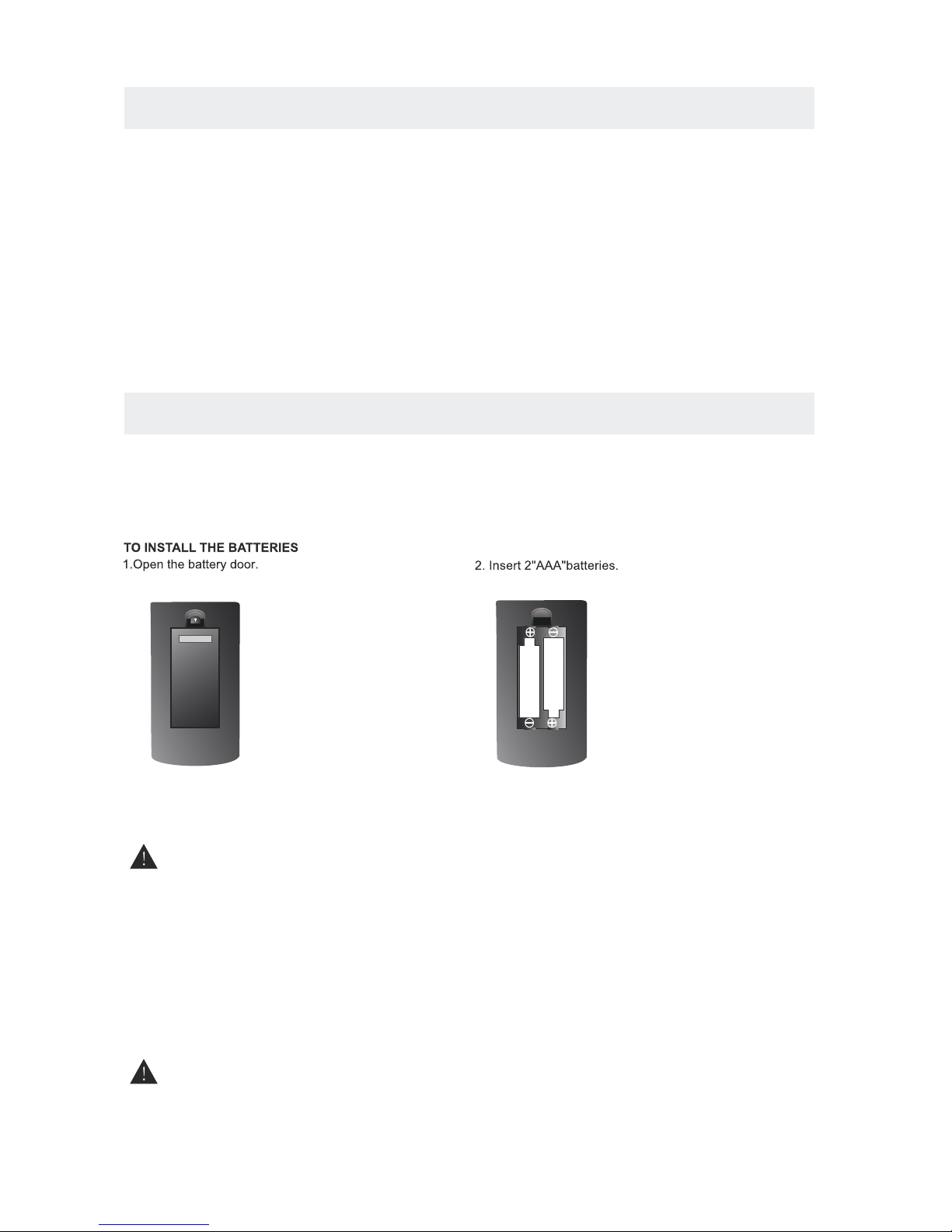
BATTERY REPLACEMENT
CAUTION
: Da nge r of e xplo sio n if ba tte r y is inc orrect ly repla ced .
NOT ES
WARNING :
3
x 2
x 1
x 1
x 1
Remo te co ntr ol .. ........ ... ... ........ ... ... ... ........ ... ... ........ ... ... ... ........ ... ... ........ ... ... ... ........ ... ... ....
Remo te co ntr ol
Batt ery (AA A)
Warr ant y Car d
Inst ruc tio n Man ual
·Poin t the r emo te co ntr ol at t he re mote senso r loc ate d on th e uni t.
·When t her e is a st ron g amb ien t lig ht source, the pe rfo rma nce o f the i nfr ared remot e sen sor
·may be d egr ade d, ca usi ng un rel iable operati on.
·The re com men ded e ffe cti ve di stance for r emo te op era tio n is ab out 1 6 feet (5 mete rs) .
When t he ba tte rie s bec ome w eak , the operating d ist anc e of th e rem ote c ont rol is greatly
redu ced a nd yo u wil l nee d to re pla ce th e batterie s.
·If the r emo te co ntr ol is n ot go ing t o be used for a long ti me, r emo ve th e bat ter ies t o avoid
dama ge ca use d by ba tte ry le aka ge co rrosion.
·Do not m ix ol d and n ew ba tte rie s. Do n ot mix ALKALINE , sta nda rd (C ARB ON- ZIN C) or
rech arg eab le (N ICK EL- CAD MIUM) batteri es.
·Alwa ys re mov e bat ter ies a s soo n as they become we ak.
·Weak b att eri es ca n lea k and s eve rely damage the r emo te co ntr ol.
Do not d isp ose b att eri es in a f ire . Batterie s may e xpl ode o r lea k.
Batt eri es sh all n ot be e xpo sed t o excessiv e hea t suc h as su nsh ine , fir e or the like.
2 Base stands and 4 screwsbase stand
..... ... ... ... .... ... ... ... ....... ... ... ... .... ... ... ... ....... ... ... ... ..
x 1
.... ... ... ... ..... ... ... ... ........ ... ... ... ..... ... ... ... ........ ... ... ........ ... ... ... ........ ... ... ........ ... .
Page 7

4
Page 8
5
Page 9
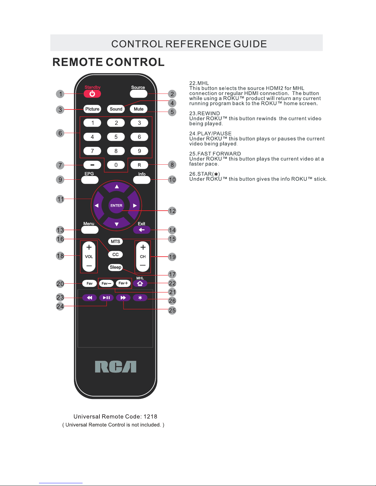
CONTROL REFERENCE GUIDE
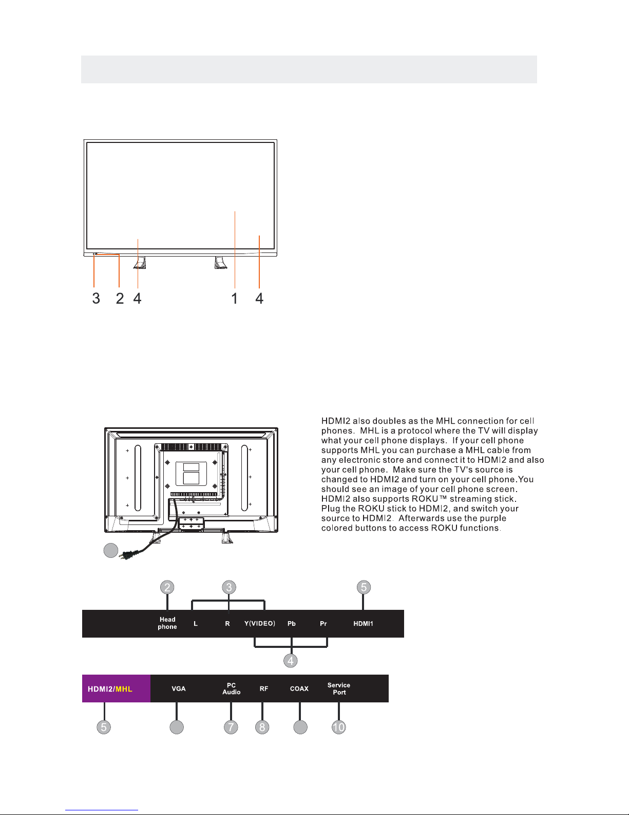
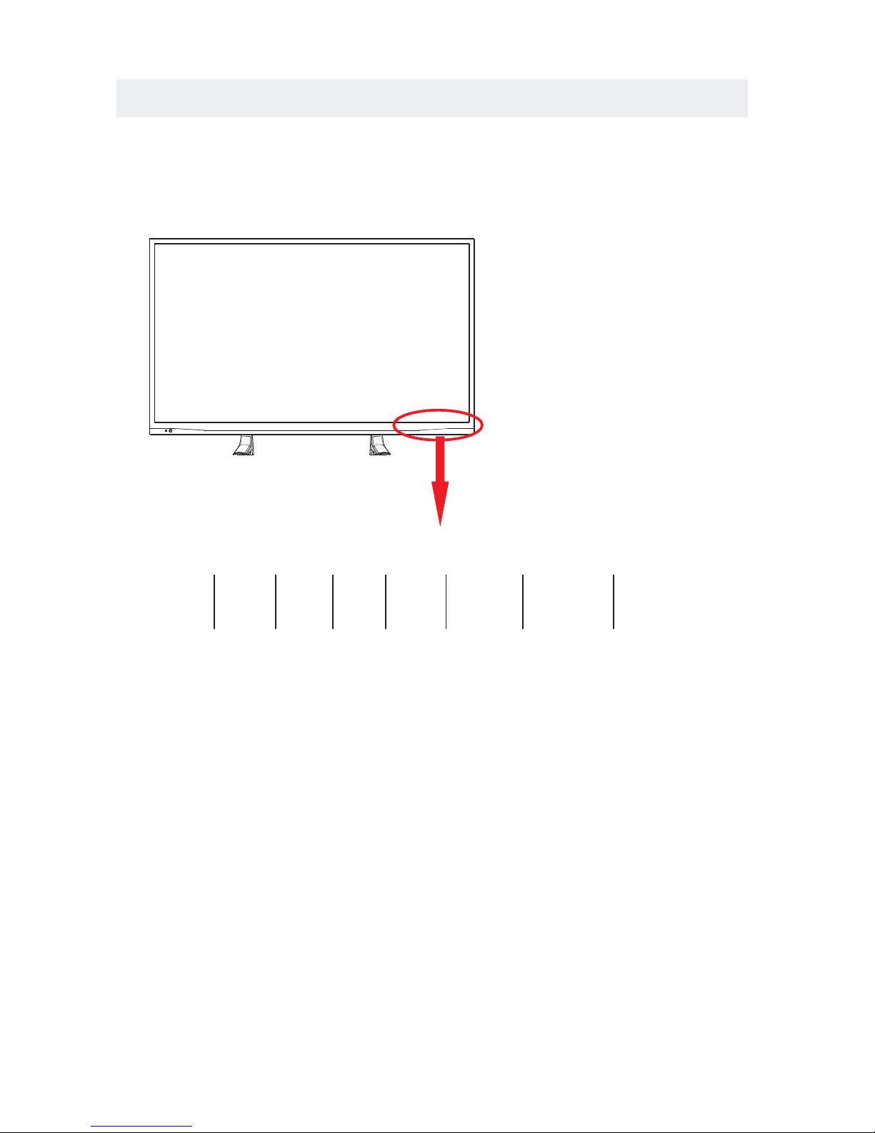
FRONT VIEW
6
BACK VIEW
1.Color Screen
2.Remote Sensor
Do not block this sensor or the
remote control will not work.
3.Standby Indicator
Indicates whether the unit is ON
or in STANDBY (OFF) mode.
Light in red: The unit is in STANDBY.
Light in blue:The unit is turned ON.
4. Speakers
1.Power Cor
2.Headphone Jack
3.AV IN Jac k
4.COMPONENT IN Jack
5.HDMI IN Jacks
6.VGA IN Jack
7.PC ADUIO IN Jack
8.TV ANTENNA Terminal
9.Coax OUT Jack
10.Service Port
d
1
6
9
Page 10
CONTROL REFERENCE GUIDE
7
FRONT VIEW
1.
Turn on the TV by pressing the button once.
Press the button again to turn off the TV.
3. MENU
This button activates the On Screen Display (OSD).
If a sub-menu is active, pressing this button will
exit the OSD.
4. CHThis button changes the TV channel down.If the
OSD is active,this button functions as down for
the menu.
5. CH+
This button changes the TV channel up.If the OSD
is active,this button functions as up for the menu.
6. VOLThis button decreases the TV's volume.If a sub-menu
is active,pressing this button will move the selection left.
7. VOL+
This button increases the TV's volume.If a sub-menu is
active,pressing this button will move the select right.
STANDBY Button
Button
Button
Button
Button
Button
Button
2. SOURCE
Press to select the input source of the TV.
VOL- VOL+ CH- CH+
MENU
SOURCE STANDBY
6 7 4 5 3 2 1
Page 11
CONNECTIONS
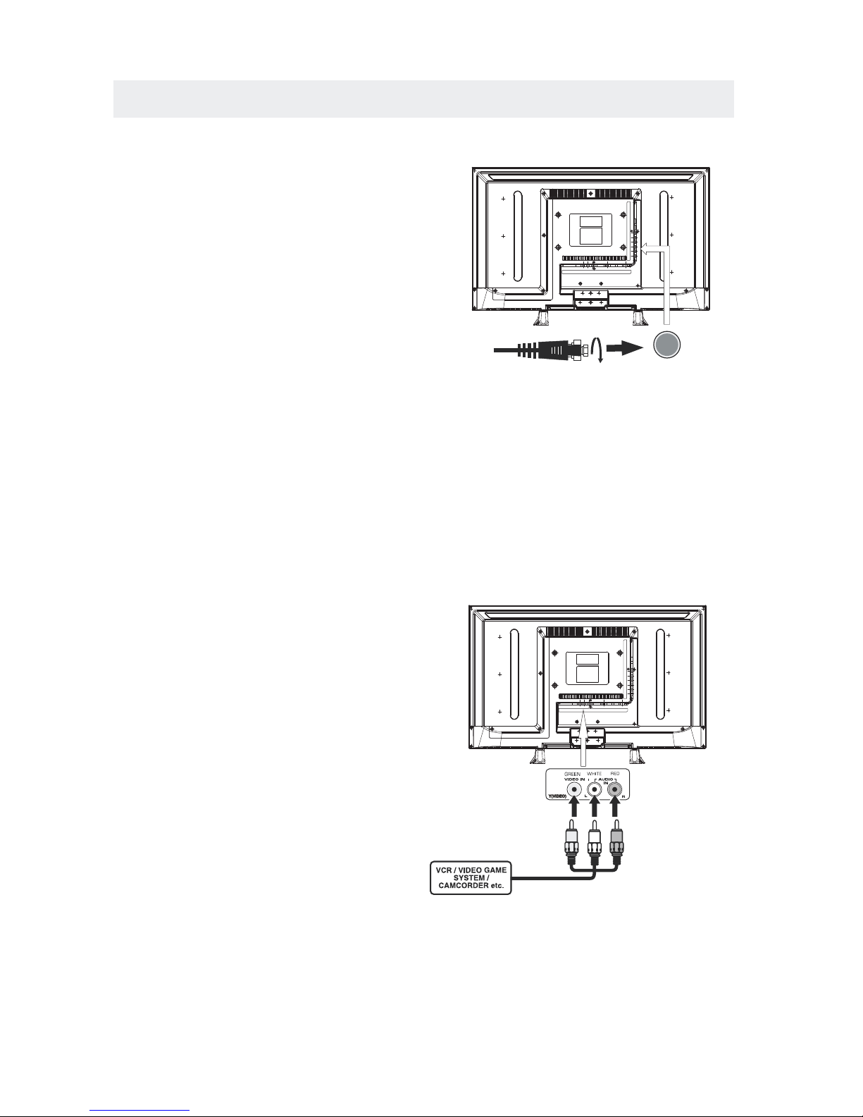
CONNECTING A T V ANTENNA / CABLE / SATELLITE
To view tel evis ion channels co rrectly, a signal mu st
be recei ved from one of the follow ing sou rces :
- An indoor or outdoo r aerial an ten na
- A ca ble sy stem
- A satellite system
Fo r rece iving over-t he-a ir TV broa dcasts, we
recom mend th at you u se an ex ter n al fixed an tenn a.
Sh ould y ou re quire the us e of a te mpor ar y a nte nna,
pl ease en sure th at you pu rcha se an ante nna wit h
su ffic ient ab ilit y to receive in wea k signa l areas .
On ly whe n you are in clo se proximity to a trans mitter
wi ll a tempor ar y an ten na reprodu ce a sig nal as
st ron gly as a fi xed antenn a.
To connec t to othe r equip ment suc h as a VCR, cam corder, satell ite sys tem or cab le, etc.
CONNECTING AN A/V DEVICE
NOTE
CONNECTING DEVICES WITH A COMPOSITE
VIDEO OUTPUT
Connecting to a VCR / Video Game System / Camcorder
AUDIO VIDEO OUT
NOTE
To con nect A /V devi ces su ch as a VCR, vi deo gam e system or ca mcorder.
Co nnec t the AUDIO / VID EO cabl e (not inc luded ) as shown .
Ma ke sure yo u conn ect th e cable f rom t he other equi pmen t ( an d ) t o this u nit
1 P. le ase refer to the us er man u al.
fo r the ot her eq uipment for
mo re inf ormation.
Sa te llite, cable or TV antenna
ca ble t o TV ANTENN A
term inal (c abl e not inc lud ed)
8
(AV in)
2. Comp osite vid eo inp ut
(shar ed with com pone nt)
To AU DI O / VIDEO
IN j ac ks
To AU DI O / VIDEO
OU T jac ks
Page 12
CONNECTIONS
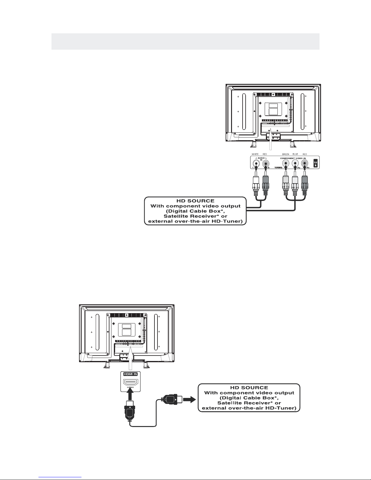
CONNECTING A HIGH-DEFINITION (HD) SOURCE USING CONNECTION
NOTE
COMPONENT
High-Definition (HD) Devices with com pon ent vi deo output must be co nne cte d to the Y input .
Connect the comp one nt vid eo cab le and au dio ca ble (n ot inc lud ed) as sh own .
Ma ke s ure you co nne ct th e com pone nt vi deo c abl e and au dio c abl e fro m the o the r equipme nt
When con nect ing a DVD play er to the telev isio n,
the pict ure resol utio n is solel y depen dent up on
the resolution sup porte d by the DVD pla yer attach ed.
DVD play er res olut ions var y from 48 0i to 108 0i.
and this telev isio n can supp or t DVD pla yers up to
a maximu m resoluti on of 108 0i.
PbPr
* May require a s ubscription
fo r recei ving HD ch annel s,
ch eck wit h your cable/s atel lite
se r v ice pro vider fo r detai ls.
To COMPO NEN T
VI DEO O UT ja cks
CONN ECTING A HIGH-DEFINITION (HD) SOURCE USING HDMI CONNECTION
HDMI (Hi gh Def ini tio n Mult ime dia In terf ace ) suppor ts bot h vide o and aud io on a si ngl e digi tal connec tio n
fo r use w ith D VD pl aye r s, DTV, set- top boxe s and o the r dig ital AV d evi ces . HDM I was de vel ope d to provi de
the tec hno logies of High Ban dwi dth Digita l Content Prot ect ion (H DCP ) as well as Digi tal Visual Inte r fac e
(D VI) i n one s pec ific ati on. H DCP i s use d to pr ote ct di git al co nte nt tra nsm itt ed an d rec eiv ed by
DVI-c omp lia nt or HDM Ico mpl iant displ ays .
HDMI has the capabi lity to supp ort stan dard, en han ced or high-defi nit ion vi deo pl us sta ndard to
multi -ch ann el sur rou nd- sou nd aud io. HDMI features inc lude uncom press ed dig ita l vi deo , a band wid th of
up to 2.2 gig aby tes pe r second (with HDTV sign als ), one co nne cto r (ins tea d of sev era l cables and
conne ctors) , and com mun ica tion betwe en the AV sourc e and AV de vic es suc h as DTVs.
To HDMI
IN jack
To HDMI
ja ckOUT
To COMPONENT
VIDEO IN jacks
AU DIO I N jack s
To COMPONENT AUDIO
OU T jac ks
Co nne ct th e HDM I cable (no t inc lud ed) a s
sh own :
Ma ke s ure you co nne ct th e cab le from th e
so urce equi pme nt ( ) to this unit
( ).
HD MI OUT
HD MI IN
HDMI CABLE
(NOT INCLUDED)
(COMPONENT OUT and AUDIO OUT)to the unit COMPONENT IN.
COMPONENT IN
9
To COMPONENT
Page 13
CONNECTIONS
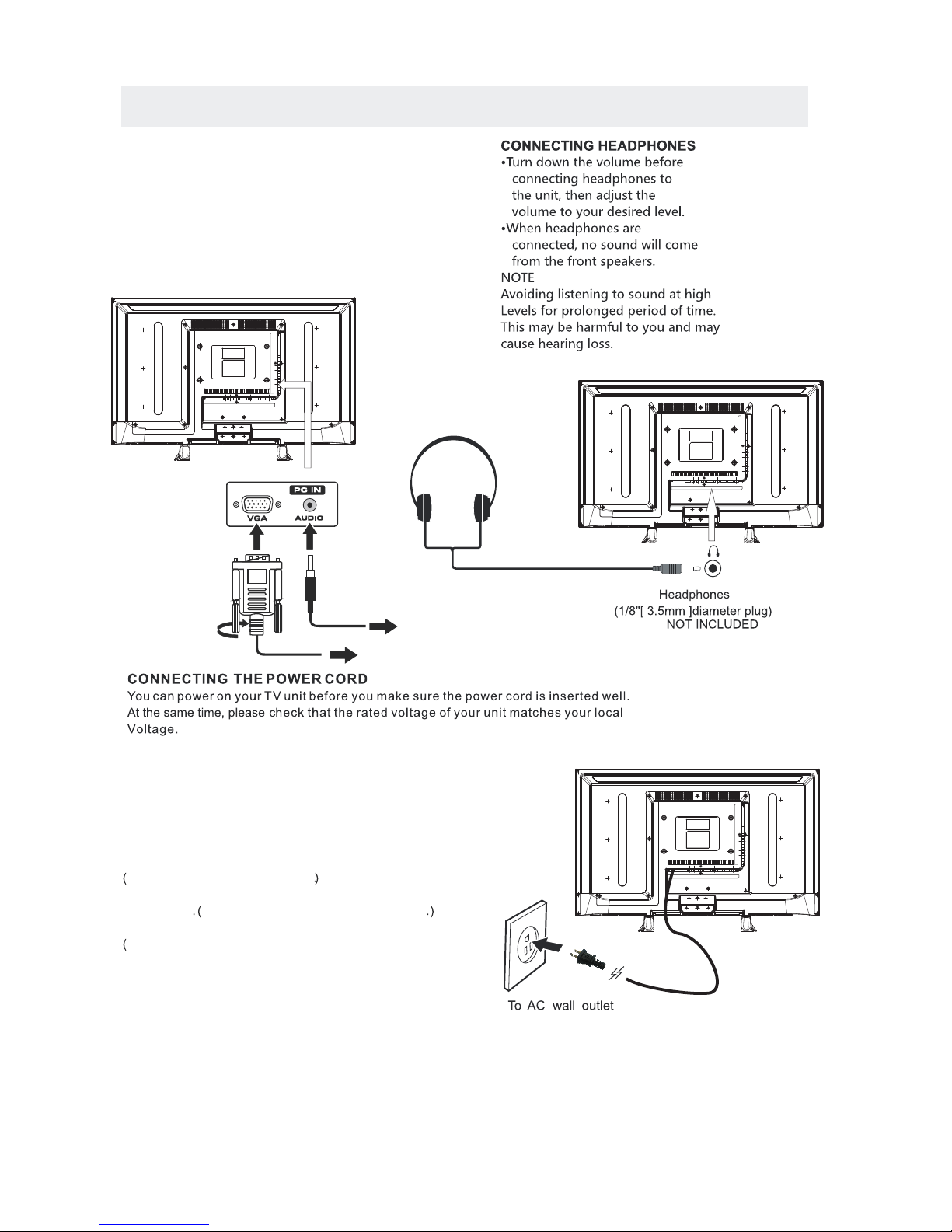
CONNECTING A
AUDI O - PC OUT
VGA AUDI O - PC IN
PC
VGA
Co nne ct the 15 -pi n D-SU B PC/VGA con nec tor
from yo ur comp uter to the 15 -pi n D- SUB PC /VGA
in put on th is uni t usin g a monitor cabl e and an
au dio ca ble (n ot inc lud ed) as sho wn.
Ma ke s ure you co nne ct th e cab le from th e computer
( an d ) to this unit
( and ) .
TO PC Con nec tor
TO AUDIO OUT jacks
NOT E
• Insert the po wer plug fu lly into th e socket ou tlet
If the pow er plug is loo se it could gen era te heat and
cause fire
Do not touch the power plug with a wet hand
This ma y cause ele ctr ical sho ck
Do not use any pow er cord oth er tha n tha t provided
with this TV This ma y cause fire or electr ica l shock
Do not damage the power cord
A damaged cord may cause fire or e lec trical shock
• Do no t mov e the TV with the co rd pl ugg ed in the
socket outle t.
• Do not pl ace a heavy object on t he cord or place
the cord nea r a high-te mpe rat ure obje ct.
• Do not tw ist the cord, bend it exce ssively , or stretch it .
• Do no t pul l on the cord. Ho ld onto the power plug bo dy when dis connecti ng cord.
• Do not us e a damaged power plu g or socket outlet.
.
( ,
.)
.
.
•
•
•
connected to prevent electrical shock.
Ensure that the power plug is easily accessible.
Ensure the earth pin on the power plug is securely
•
•
10
.)
Page 14

CONNECTIONS
Connection to a Home Theater Audio System
For BEST audio performance
Connecting to a Home Theater System
Dolby Digital can deliver optimal 2 channel
stereo or surround sound with five discrete
full range channels plus a sixth channel for
a subwoofer.
Enjoy optimal sound reproduction from your
system with a Dolby Digital amplifier that
incorporates a digital coaxial input. Connect
an optional digital cable directly to the
television’s Coax audio output to listen
through all inputs except VGA.
(The VGA does not support digital audio)
How To Setup Digital Output
Press the MENU button on the remote control
Press the right ► arrow button to select sound
Press the down ▼ arrow button to highlight
SPDIF type right ► Raw or PCM
11
Set up
12
6
Time
Equa lizer S ettin gs
MTS
Audio Language
AVL
Surround Sound
Move Sel ec t Exit
MEN U
Off
Pic ture
Sound
Englis h
Digi ta l Audi o Ou tpu t
PCM
Off
Stereo
Coax
SPD IF OUT
Page 15

WALL MOUNT INSTALLATION
INSTALLING REMOVING THE BA SE STA ND
WARNING/: The LED Di splay is ve ry fr agi le an d must b e pro tec ted a t all t imes when remo vin g the b ase
Stan d
Be sure that no hard or sharp ob jec t or an ything that could scra tch or damage the LED displa y comes into
contact with it Do NOT exert pressure on the front of the unit at any time because the screen could crack
1 Disconnect all cables or cords con nec ted to the uni t
2 Lay the unit down on a flat su rface with the back side f aci ng up Please ma ke sure to place a soft
cushioned material such as a pillow or thick piece of foam beneath the screen
3 To remove the base stand loosen screws off the h ole s then pull downwards to release
the base stand
,
.
. .
. .
MO UNT ING ON TH E WAL L
NOT E
Remo ve the base st and before mounting th e unit on th e wall .
This un it is VESA-com pli ant , and is desig ned to be wall -mo unt ed with a VE SA- complian t 8"x4 "
(200mm x 100mm ) mounting kit de sig ned fo r fla t-panel TVs (not supplie d). Mo unt this un it acc ording to
the ins tru cti ons incl ude d in the mount ing ki t.
Length of screw should not exceed 10 mm.
12
8"
4"
M6
Page 16

INITIAL SETUP
Wh en you t urn on your tel evision set f or
th e first t ime, be s ure t o place i t on a sol id
st able su r f ace.
To avo id danger, do n ot exp ose the T V
to wate r, or a he at source
(e .g. lam p, candl e, radia tor) .
Do not obstr uct the ven tila tion gri d
at t he re ar and be s ure to leave s uffic ient
ga ps arou nd the uni t.
PUTTING THE UNIT ON A PROPER PLACE
TU R N ING THE UNIT O N F O R THE FIRST TI M E
Af ter you have initia lly conne cted you r TV
antenna o r c able,
tu rn the telev ision ON.
A screen wil l display asking you to ru n a
to se arch and receive
availa ble loca l di gital ch annels .
It is he re where you will sele ct antenn a option s
an d run .
Channel s w ill be sto red in th e T V tuner .
Press the bu tton on the remote con trol.
Pr ess the button to h ighli ght AIR/ CABLE.
Ch a nne l Au to Scan
Ch a nne l Au to Scan
ME N U
Using the buttons, scroll to highlight chaneel mode.
1. Press the butto n on the remo te cont rol.
2.
and selec t a ny of th e m using the butt o n or
the button.
ource
Note:
Be fore watch ing please make sure all necess ary
cables and devic es are connect ed.
EN TER
Us e or button to sel ect th e optio nsthe
(T he screen wi l l chan ge to yo ur desi red s ).
(TV,YPbPr/ , HDMI1,HDMI2,PC)AV
13
Source Select
TV
YPbPr/
HDMI1
HDMI2/MHL
PC
AV
Source Select
TV
YPbPr/
HDMI1
ROKU
PC
AV
Page 17

TV SETUP
14
Press MENU button to display the main menu.
Press ◄ / ► button to select CHANNEL in the main menu,it will highlight the first option.
Se tup
LOC K
12
6
Time
Pic ture
Sound
CHA NNEL
Air
/
Cable
Au to Sca n
Fa vor ite
Show Hid e
Ch annel Nu mber
Ch ann el labe l
Ch annel L ist
Air
Se lec t ExitMo ve
MEN U
Mo ve
MEN U
AIR / CABLE
This feature allows you to switch between air (such as using antenna) and cable.
AUTO SCAN
This feature searches channels automatically for you.
FAVORITE
This feature gives the favorite list of channels added by you.
CHANNEL LIST
This feature shows the list of stored channels.
SHOW / HIDE
This feature tells you if you have chosen for channel to be skipped.
CHANNEL NUMBER
This feature tells you what channel you are currently on.
CHANNEL LABEL
This feature changes the name of the channel.
Please Note:
The channel options are only available when you select TV as your SOURCE.
When you open the OSD menu on other sources (HDMI, YPbPr/AV, PC) these
options will be grayed out.
CHANNEL MENU
Page 18

TV SETUP
15
Press MENU button to display the main menu.
Press ◄ / ► button to select PICTURE in the main menu,it will highlight the first option.
PICTURE MODE
This feature changes various color modes for the TV.
BRIGHTNESS
This feature changes the picture's detail in dark colors.
CONTRAST
This feature changes the difference between dark and bright objects.
COLOR
This feature changes the amount of color in the picture.
TINT
This feature changes the white balance of the color.
SHARPNESS
This feature changes the picture quality.
COLOR TEMPERATURE
This feature adjusts the color temperature of the TV, giving warm, normal,
cool.
ADVANCED SETTINGS
a)ASPECT RATIO This feature changes the various aspects of the TV's video.
(Aspects include wide, zoom, cinema,normal).
b)NOISE REDUCTION This feature reduces general pixilation by blurring them.
c)DYNAMIC CONTRAST This feature allows the TV to automatically adjust the contrast of the
TV depending on the picture you are viewing.
PICTURE MENU
Se tup
12
6
Time
Pic ture
Sound
Pictu re Mode
Co ntra s t
Brigh tnes s
Co lor
Tint
Sh arpness
Co lor Tem p eratu r e
St and ard
No rma l
Mo ve Se lec t Exit
MEN U
50
50
50
0
50
Ad v ance d S ettin g s
Page 19

TV SETUP
16
Press MENU button to display the main menu.
Press ◄ / ►button to select SOUND in the main menu,it will highlight the first option.
EQUALIZER SETTINGS
This feature enables the internal equalizer of the speakers.
You can adjust the settings individually or use the presets (standard, music, movie, sports, user).
MTS
This feature adjusts the second audio programming in analog channels.
AUDIO LANGUAGE
This feature adjusts the digital second audio programming in digital channels.
DIGITAL AUDIO OUTPUT
This feature adjusts the digital audio output.
SURROUND SOUND
This feature adjusts the dimensional surround effect on or off (for built-in speakers only).
AVL
This feature adjusts the auto volume leveler enabling volume protection from overly loud
commercials.
SOUND MENU
Se tup
12
6
Time
Eq uali zer Se t ting s
MT S
Audio Language
AV L
Surround Sound
Mo ve Se lec t Exit
MEN U
Of f
Pictu re
Sound
En gli sh
Di gita l Audi o Outp ut
PC M
Of f
Stere o
Please Note:
AUDIO LANGUAGE and MTS are dependent on the broadcasting station's support and are only
available under the source TV.
Page 20

TV SETUP
17
Press MENU button to display the main menu.
Press ◄ / ►button to select TIME in the main menu,it will highlight the first option.
TIME MENU
Set up
Sl eep Time r
Time Z on e
Da yli g ht S avin g Time
Cl ock
Mo ve Se lec t Exit
MEN U
Pic tu re
Of f
Pa cif ic
Of f
2013 /01 /01 12: 00 AM
12
6
Time
Sound
Time Format
12 -ho ur
Auto Clock On
SLEEP TIMER
This timer automatically turns off the TV at the designated time.
TIME ZONE
This option adjusts the global time zone for the TV.
DAYLIGHT SAVING TIME
This option toggles the daylight saving time feature.
TIME FORMAT
This option adjusts the display format for the time.
AUTO CLOCK
This option enables the TV to sync time with the antenna.
(Put it on AUTO if you have an antenna attached to the TV.If you have CABLE or SATELLITE or
anything else please use make sure AUTO CLOCK is turned off)
CLOCK
This option adjusts the time and date of the TV.You need to disable AUTO CLOCK in order to
use this function.
Please Note:
The TIME function will only keep accurate time if the TV is plugged into a power source.
If the TV is unplugged or the power strip is turned off, the TV's time will not be accurate.
Page 21

TV SETUP
18
Press MENU button to display the main menu.
Press ◄ / ► button to select SETUP in the main menu,it will highlight the first option.
SETUP MENU
Loc k
12
6
Time
Ch ann el
Me nu L angu age
Tra nsp aren cy
Zoom Mod e
No ise R edu c tio n
Ad van ce
Cl ose Capti on
XVS
Re sto re Def ault
En gli sh
Mo ve Se lect Exit
MEN U
Pic tu re
Off
No rma l
Set up
Audio
On
12
6
Time
Me nu L angu age
Tra nsp aren t
OS D Time out
Cl ose d Capt ion
In put l abel
Ot her S etti ngs
Setup Wizard
Re sto re Def ault
En gli sh
Mo ve Se lect Exit
MEN U
Pic tu re
25 %
30 S ec.
Set up
Sound
MENU LANGUAGE
This option changes the language of the TV's OSD menu.
TRANSPARENT
This option changes the transparency of the menu allowing background TV images to show through.
OSD TIMEOUT
This option changes the time which the TV's OSD menu automatically goes off.
CLOSED CAPTION
This option displays words on the TV.
INPUT LABEL
This option changes the source names to your personal preference.
OTHER SETTINGS
This option adjusts miscellaneous options of the TV.
AUDIO ONLY-This option turns off the screen while the audio is still playing.
RESTORE DEFAULT
This option restores all the changes in the OSD menu back to the default factory settings.
SETUP WIZARD
This option enables the TV to show you the setup wizard of the TV again.
Please Note:
Closed captioning is only available under AV and TV ports.
Closed captioning depends on your TV program's support. Sometimes due to the TV channel
or the signal, closed captioning will not be available.
In United States, closed captioning under analog signals is CC1.
In United States, closed captioning under digital signal is Service1.
Page 22

TV SETUP
19
Press MENU button to display the main menu.
Press ◄ / ► button to select LOCK in the main menu,it will highlight the first option.
Press “0000” for the lock password.
LOCK MENU
CHANGE PASSWORD
This option allows you to change the LOCK menu password.
SYSTEM LOCK
This option enables parental locking and filtering for the TV.
US RATING
This option filters US TV programming and movies.
CANADA RATING
This option filters CANADA TV ratings.
RRT SETTING
This feature is a downloadable rating filter based on TV broadcasts. With the transition of TV
broadcasts to digital, future changes, and enhancements in how TV shows are rated for content
are possible.
RESET RRT
This option resets the RRT5 settings.
Please Note:
Please refer to RATINGS EXPLAINED for more information on ratings definitions.
Downloadable rating and clear downloadable data might be grayed out depending on the Tvs
tations support.
RRT5 options are based on TV broadcasts, if it is grayed out, then it is not available in your region.
12
6
Page 23

Hi!
Let’s get started.
20
Page 24

Roku Streaming Stick
TM
High speed
Internet
What you need
Wireless Router
21
Page 25

Know your
Streaming Stick
[MHL CONNECTOR] Plugs into the
MHL port on the back of your TV.
[STATUS LIGHT] Signifies it is on
when lit, or activity when flashing.
[RESET BUTTON] Used to reset
your Streaming Stick
22
Page 26

What to do
Plug it in
Plug your Roku Streaming Stick into
the MHL port of your Roku Ready TV.
Simple as that!
CO IA V
HDMI2/MHL HDMI3
23
Page 27

Connect to network
Now you can grab your remote
and jump right into guided
setup. Have your network name
and password ready and do the
following:
Select your network from the
list of available networks.
Enter your network password,
if you use one. Remember,
network passwords are case
sensitive.
24
Page 28

Complete guided setup
It’s the final stretch and hooray—it’s
on-screen instructions and you’ll:
Get the latest software.
Link the Roku Streaming Stick
to your Roku account on your
computer.
What to do (cont.)
!
25
Page 29

Your Roku account:
During setup, you’ll be
prompted to create
your Roku account
online at roku.com/link. Your Roku
Streaming Stick will generate
a unique code that links your
player to your new account. Roku
accounts are free and secure. And
while a valid credit card number is
required to create your account,
rest assured you will only be
charged if you authorize purchases
of channels and games from the
Roku Channel Store.
26
Page 30

Having trouble completing setup?
Don’t worry: it’s usually an easy fix.
If you cannot see a picture on
your TV:
Make sure your TV is turned
on. (This tip could save you
some embarrassment.)
Make sure the video input
on your TV or home theater
receiver is set to match the
output (usually HDMI or MHL)
used with the Roku Streaming
Stick. Most TVs have an Input button
(or a source button) on the remote
control to change video inputs.
Troubleshooting
27
Page 31

If you cannot connect to your
wireless home network during
guided setup:
If you are not getting 3 or
more signal-strength bars
above your wireless network,
adjust the location of your
Roku Streaming Stick and/
or wireless router. Make sure
there are no obstructions, like
cement walls, between your
Roku Streaming Stick and your
wireless router.
Make sure you select the
correct wireless router name
on the “Wireless” screen.
28
Page 32

Troubleshooting (cont.)
Make sure you enter the
correct password, if your
network is security-enabled
(password is case sensitive).
If you have turned o
SSID broadcasting on your
wireless router, you can add
your network by selecting
“My network is not shown”
from the “Wireless” screen.
If you cannot hear sound:
Make sure the connectors on
the cables between your TV
and home theater receiver
are pushed in all the way.
29
Page 33

(cont.)
Make sure the volume on your
TV or home theater receiver is
turned up and isn’t on mute.
30
Page 34

Roku Streaming Stick
Important Product Information
The License Agreement
The Roku and third-party software license terms can be found at: www.roku.com/
license. Use of the Roku Streaming Stick (“Streaming Stick ”) constitutes acceptance
of as well as agreement to those license terms.
One (1) Year Limited Hardware Warranty
Subject to the additional terms and conditions set forth below, Roku provides this
Limited Warranty:
Roku or from one of its authorized re-sellers or distributors; and
United States and Canada.
Limited Warranty
Roku warrants the Streaming Stick hardware against defects in materials and
workmanship under normal use for a period of o n e ( 1 ) y e a r from the date
of purchase (“Warranty Period”). If Roku determines that the Streaming Stick’s
hardware is defective, Roku will either repair the unit or replace the unit with either
a new or rebuilt Streaming Stick, at its option. If the Warranty Period has expired
or is otherwise not applicable (see Scope and Limitation on Warranty below), we
will return the Streaming Stick to you. More information about this warranty can
Return and Warranty Service Process
Please access and review the online help resources at www.roku.com/support
before seeking warranty service. To return or obtain warranty service for a
number from a Customer Support Representative (CSR) at Roku. Customer Support
expire thirty days from issuance. Roku may attempt to troubleshoot a warranty-
ship your Streaming Stick, freight prepaid, together with proof of purchase and all
accessories, in either the original packaging or pa
of protection, to the Roku authorized distribution facility identifi ed by the CSR.
Failure to return any of the accessories could result in a delay and/or result in an
invoice to you or credit to Roku for the missing accessories
.
TM
31
Page 35

Important:
with your request: (a) model number, (b) serial number, (c) problem description, (d)
software version (located in the System Configuration menu), (e) date of purchase,
(f) place of purchase (re-seller or online place of purchase), and (g) return shipping
Scope of and Limitation on Warranty
The warranty on the Streaming Stick is limited to the repair or replacement of defective
units as described in the Limited Warranty section above. This warranty does not cover
customer training or education, installation, set up adjustments, or signal reception
problems. This warranty also does not cover any issue related to the service provided
by your Service Provider, including but not limited to service disruption, changes
negligence, commercial use or modification of, or to any part of, your Streaming Stick.
This warranty does not cover damage due to improper operation or maintenance,
connection to improper voltage supply or attempted repair by anyone other than a
facility authorized by Roku to service your Streaming Stick. This warranty does not
cover consumables (such as fuses and batteries).
Legal Notices
Federal Communication Commission Interference Statement
digital device, pursuant to Part 15 of the FCC Rules. These limits are designed to
provide reasonable protection against harmful interference in a residential installation.
This equipment generates, uses and can radiate radio frequency energy and, if not
installed and used in accordance with the instructions, may cause harmful interference
to radio communications. However, there is no guarantee that interference will not
occur in a particular installation. If this equipment does cause harmful interference to
and on, the user is encouraged to try to correct the interference by one of the following
measures:
receiver is connected.
following two conditions: (1) This device may not cause harmful interference, and (2)
this device must accept any interference received, including interference that may
cause undesired operation.
32
Page 36

FCC Caution:
responsible for compliance could void the user’s authority to operate this equipment.
channels 1 through 11.
Wireless Radio Use:
band.
IMPORTANT NOTE:
FCC Radiation Exposure Statement:
This equipment complies with FCC radiation exposure limits set forth for an
uncontrolled environment. This equipment should be installed and operated with
minimum distance 20cm between the radiator and your body.
This transmitter must not be co-located or operating in conjunction with any other
antenna or transmitter.
Note to US model owner:
To comply with US FCC regulation, the country selection function has been completely
removed from all US models.
The availability of some specific channels and/or operational frequency bands
are country dependent and are firmware programmed at the factory to match the
intended destination. The firmware setting is not accessible by the end user.
Safety Precautions
The Streaming Stick has been designed with the highest concern for safety. However,
any electrical device, if used improperly, has the potential for causing fire, electrical
shock or personal injury.Tohelp ensure accident-free operation, follow these guidelines:
electrical outlet and disconnect any other cables immediately if the Streaming Stick
or the device functions in an abnormal manner, produces unusual sounds or smells or
becomes too hot to touch.
roku.com/support.
33
Page 37

trademarks or registered trademarks of Roku, Inc.
Use and Handling
of small children.
Stick or accessories.
humidity or direct sunlight.
www.roku.com
34
Page 38

DISPLAY MODE
35
PC FORMATS
Ho
r
iz
ontal
S
can
n
i
n
g
Frequ
ency
Reso
lut
ion
(KHz
)
Ve
r
ti
c
a
l
S
ca
n
n
i
n
g Frequ
ency
(H
z
)
F
orm
a
t
6
4
0
4
80
8
00 6
0
0
8
0
0
60
0
1
0
2
4
7
6
8
1
3
60 7
6
8
4
7. 7
31. 5
X
X
X
X
X
NOTE:
This product does not support the display mode not listed above.
In order to achieve the best display effect, please select the above-listed
5 display modes input signal.
Because of the difference of display drivers output signal
(especially non-standard signal output), the display image may appear little
disturbance which can be adjusted on the PC menu.
To prolong this unit's service life, please set your computer to power management mode.
Page 39

DISPLAY MODE
VIDEO FORMATS
SUPPORTED COMPONENT / HDMI INPUT MODE
Horizontal
Scanning Frequency
Vertical
Scanning Frequency
Format
(Hz)
720 480
720 480
1280 720
1280 720
1920 1080
31. 47
15. 734
37. 5
45
31. 25
33. 75
59. 94
59. 94
50
60
50
60
480 p
480 i
1080 i
720 p
720 p
1080 i
Re
so
l
u
t
i
o
n
X
X
X
X
The above listed formats are also related to the AV devices you are about to connect.
Before you connect this unit with others please read all instructions carefully and
make sure all necessary cables are connected.
.
This unit may be incompatible with some other formats which are not meet the
above conditions.
NOTE:
1920 1080
X
X
1920 1080
X
1920 1080
X
1080 p
1080 p
1920 1080
X
1080 p
50
60
24
27
56. 25
67. 50
36
Page 40

SPECIFICATION
This manual is only for your reference.
Specifications are subject to update without prior notice.
37
32"LED TV
Panel Type
32 inches
Diagonal Size
Screen Format 16 9:
Color System
ATSC/QAM/NTSC
Model Description
Panel
Resolution 1366x 768
View Angle
Response Time
Contrast
Brightness
Maximum Color
230 cd/m²
1200:1
16.7M colors
Sound Output
RF Input 75 ohm external terminal
HDMI Input
Video 480i 480p 720p 1080i, 1080p.: , , ,
Audio Two channel linear PCM 32 44 1 and 48kHz 16 20 and 24 bits: , . , ,
PC RGB Input-
D sub 15pinG 0 7Vp p 75ohms: . - ,
B 0 7Vp p 75ohms: . - ,
R 0 7Vp p 75ohms: . - ,
Power Requirement
Input /
Output
Jacks
Systems
Power
Sound System
M
Audio System
BTSC
L/R Speaker:8W+ 8W
Composite Video Input
Component Y Pb Pr Input/
Sound Input
PC AUDIO: For PC RGB Audio input
500mV rms, Impedance: 20k ohms
RCA
Y: 1.0 Vp-p, 75ohms, 0.3V negative sync
Pb: 0.7Vp-p, 75ohms
Pr : 0.7Vp-p, 75ohms
100-240V~ 50/60Hz
178( H)/ 178(V)
60 W
1.0 Vp-p, 75oh ms RCA
AV AUDIO: For CVBS/COMPONENT Audio input
Rated Power Consumption
8 ms
LED Panel
Page 41

SYMPTOM CAUSE AND REMEDY( )
TV
Bad
Picture
(snow,
multiple
images
distortion,blurry)
No sound.
Black
and
White
picture.
No picture or sound.
Coloredpatches of
picture.
Panel function key does
not respond correctly.
• Check the location of the antenna and adjust it if necessary.
• Make sure the antenna cable is firmly connected.
• Make sure all input cables are firmly connected.
• Increase the volume.
• Check the PICTURE setting within the PICTURE menu.
• Make sure the unit is plugged in and turned on.
• Make sure that the ATV mode is selected.
• Try a new channel to check for possible station trouble.
• Make sure the antenna is connected properly.
• Increase the volume.
•
• Make sure all cables are firmly connected.
• Check for local interference.
• Make sure there are no unshielded electrical devices nearby
that are causing interference.
• Turn the TV off for 30 minutes, then try it again.
• Under the influence of electrostatic phenomenon, the product
may malfunction and require usertopowerreset.
• Unplug and re-plug the AC power cord.
TROUBLESHOOTING GUIDE
• Check to make sure the program you are watching is broadcast
in Color and not Black & White.
• Check
whether the mute function has been activated on the
Remote Control.
The display monitor's
panel goes hot.
• LED TV takes inside lighten phosphor. It may increase the
temperature of the screen in some occasions. It's not a defect.
Unusual dots
• Black dots and Bright points may appear on the LED screen.
This is a structural property of the LED panel and is not a defect.
Stripes on screen
•
Adjust the impulse phase may decrease stripes. RGB in
The top of the monitor
• It may occur during long-time working. It's not a defect.
gets hot
.
Make sure the antenna or audio/video source device is
working properly.
Unable to selec t a
certain channel.
The channel may be skipped. Choose this channel by
directly selecting the buttons from the remote control.
•
Disorder display
at power on.
••This may be caused because of a very short interval
between POWER OFF and ON.
Unplug the powe r and restart.
38
 Loading...