

RCA RLDED3231A-B-RK Instruction Manual
Model:RLDED3231A-B-RK

CONTENTS
13
14
15
16
17
18
1
2
2
3
3
6
7
3
4
8
9
7
8
8
9
9
4
5
5
6
11
12
12
12
SAFETY
PRECAUTION
IMPORTANT
SAFETY
INSTRUCTION
ACCESSORIES
GETTING
STARTED
5
CONTROL
REFERENCE
GUIDE
WALL MOUNT
INSTALLATION
INITIAL SETUP
TV SETUP
CONNECTIONS
Remote Control
Front View
Back View
Side View
Antenna Connection
AV Connection
YPbPr Connection
HDMI Connection
VGA Connection
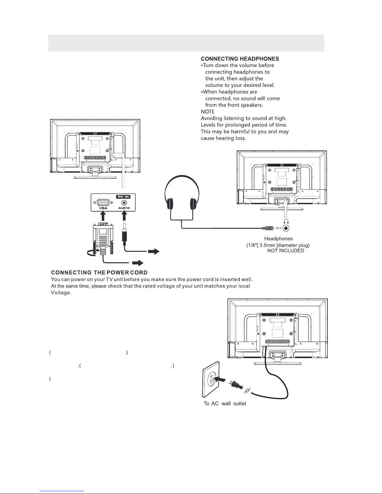
Headphone Connection
Power Cord Connection
Coax(SPDIF) Connection
Putting The Unit On A Proper Place
Source Selection
Turning The Unit On For The First Time
TV(CHANNEL) Menu
Picture Menu
Audio Menu
Time Menu
Setup Menu
LOCK(Parental) Menu
1
English
10
7
9

CONTENTS
19
10
21
11
12
22
DISPLAY
MODE
SPECIFICATION
TROUBLESHOOTING
GUIDE
PC Formats
Video Formats
TV Symptom
SAFETY CLASS :This is an IEC safety class I product
and it must be grounded for safety.
20
*
SAFETY PRECAUTION
CAUTION
•
•
•
WARNING:
PLACEMENT INFORMATION
SAFETY INFORMATION
RATING PLATE LOCATION
FCC STATEMENTS
WARNING:
CAUTION MARKING WAS LOCATED AT THE REAR
OF THE APPARATUS.
WARNING: TO REDUCE THE RISK OF ELECTRIC
SHOCK,DO NOT REMOVE COVER(OR BACK)
NO USER SERVICEABLE PARTS INSIDE.
REFER SERVICING TO QUALIFIED SERVICE
PERSONNEL.
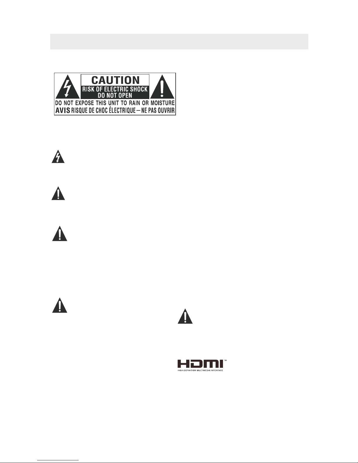
The lightning flash with arrowhead symbol,
within an equilateral triangle,is intended to
alert the user to the presence of uninsulated
“dangerous voltage”within the product's enclosure
that may beof sufficient magnitude to constitute a
risk of electric shock to persons.
The exclamation point within an equilateral
Triangle is intended to alert the user to
The presence of important operating and
maintenance (servicing) instructions in the literature
accompanying the appliance.
DANG ER OF EXP LOS ION IF BA TTERY I S
INCORRECTLY REPLACED. REPLACE ONLY
WITH THE SAME OR EQUIVALENT TYPE.
USE OF C ONTRO LS OR A DJUST MENTS O R
PERFORMANCE OF PROCEDURES OTHER
THAN THOSE SPECIFIED MAY RESULT IN
HAZARDOUS RADIATION EXPOSURE.
•
•
TO RED UCE THE R ISK O F FIRE OR E LECTR IC
SHOC K, DO NOT E XPO SE THIS A PPLIA NCE TO
RAIN O R MOIST URE .
TO REVENT FIRE OR SHOCK HAZARD, DO NOT
EXPOSE THIS UNIT TO RAIN OR MOISTURE. DO
NOT PL ACE OBJ ECT S FILLE D WITH LI QUIDS O N
OR NEA R THIS UN IT.
SHOULD ANY TROUBLE OCCUR, DISCONNECT
THE AC P OWER CO RD AN D REFER S ERVIC ING
TO A QUA LIFIED TECHNICIAN.
Do not u se this u nit i n place s that ar e ext remel y
hot, c old, du sty o r humid .
Do not r estri ct th e airfl ow of thi s uni t by p lac ing it
some where w ith p oor air flow, b y cov ering i t with
a cloth, by placing it on bedding or carpeting.
When connecting or disconnecting the AC power
cord, grip the plug and not the cord itself. Pulling
the co rd may da mag e it and cr eate a ha zar d.
When y ou are no t goi ng to use t he unit f or a lo ng
period of time, disconnect the AC power cord.
The ra ting pl ate i s locat ed on the r ear o f the uni t.
NOTE : This un it ha s been te sted an d fou nd t o com ply
with t he limi ts fo r a Class B d igita l dev ice, pu rsuant
to Par t 15 of the F CC Ru les. Th ese lim its a re d esi gned
to provide reasonable protection against harmful
inte rfere nce i n a residential installation.
This unit generates, uses and can radiate radio
frequency energy and, if not installed and used in
accordance with the instructions, may cause harmful
interference to radio communication. However, there
is no guarantee that interference will not occur in a
particular installation. If this unit does cause harmful
interference to radio or television reception, which
can be d eterm ine d by turn ing the u nit o ff and on , the
user i s encou rag ed to try t o corre ct th e in ter feren ce
by one o r more of t he fo llowi ng meas ure s:
- Reorient or relocate the receiving antenna.
- Increase the separation between the unit and
receiver.
-Connect the unit into an outlet on a cir cui t diffe rent
from that to which the receiver is connected.
- Consult the dealer or an experienced radio/TV
technician for help.
Changes or modifications to this
unit not expressly approved by the party responsible
for compliance could void the user authority
to operate the unit.
•
•
•
•
“HDMI, the HDMI logo and High-Definition Multimedia
Interface are trademarks or registered trademarks of
HDMI Licensing LLC.”
1

IMPORTANT SAFETY INSTRUCTIONS
1)Read these instructions.
2)Keep these instructions.
3)Heed all warnings.
4)Follow all instructions.
5)Do not use this apparatus near water.
6)Cle an on ly with a d ry clot h.
7)Do not block any ventilation openings.
Install in accordance with the
manufacturer's instructions.
8)Do no t ins ta ll ne ar any he at sour ces s uch
as radiators, heat registers, stoves, or
other apparatus (Including amplifiers) that
produce heat.
9)Do no t def ect the s afety p urpos e of th e
polarized or grounding-type plug.
A polarized plug has two blades with one
wide r than th e oth er.
A groundingtype plug has two blades
and a th ird grounding prong.
The wi de bl ad e or th e third p rong is
prov ided for your safety.
If the p rovid ed pl ug does n ot fit in to yo ur
wall o utl et , con sult an electrician for
replacement of the obsolete outlet.
10)Protect the power cord from being walked on
or pin ched pa rti cularly at plugs, convenience
rece ptacl es, a nd the po int whe re th ey exit
from t he apparatus.
11)On ly us e at tac hment s / acces sor ies spe cifie d
by the m anufacturer.
12)Use only with the cart, stand,
tripod, bracket, or table
spec ified b y the m anufacturer,
or sol d with th e apparatus.
When a c art is us ed, u se caut ion when
movi ng the ca rt / apparatus combination to
avoi d injur y fro m tip-o ver.
13)Unplug this apparatus during lightning
Stor ms or whe n unused for long periods of
time .
14)Refer all servicing to qualified service
pers onnel. Servicing is required when the
a
pparatushas been damaged in any way,
such a s the power cord or plug is damaged,
liquid has been spilled or objects have fallen
into t he apparatus, the apparatus has been
expo sed to ra in or m oistu re, doe s not o perat e
norm ally, or has been dropped.
15)To prevent electric shock, ensure the grounding
pin on t he AC cor d power plug is securely
connected.
2
ACCESSORIES
Please check and identify the supplied accessories.
GETTING STARTED
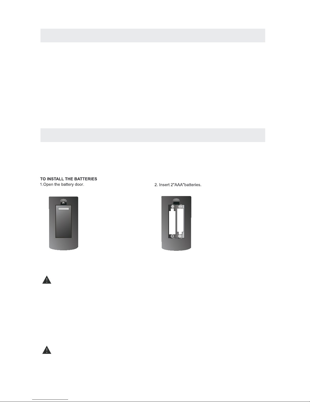
USING THE REMOTE CONTROL
BATTERY REPLACEMENT
CAUTION
: Danger of explosion if battery is incorrectly replaced.
NOTES
WARNING :
·Poin t the r emote c ontro l at th e remot e senso r loc ated on t he unit.
·When t her e is a stro ng ambient light source, the performance of the infrared remote sensor
·may be degraded, causing unreliable operation.
·The recommended effective distance for remote operation is about 16 feet (5 meters).
When the batteries become weak, the operating distance of the remote control is greatly
reduced and you will need to replace the batteries.
·If the r emo te cont rol is no t goi ng to be us ed for a lo ng ti me, rem ove the b att eries t o avoid
damage caused by battery leakage corrosion.
·Do not mix old and new batteries. Do not mix ALKALINE, standard (CARBON-ZINC) or
rechargeable (NICKEL-CADMIUM) batteries.
·Always remove batteries as soon as they become weak.
·Weak batteries can leak and severely damage the remote control.
Do not d ispose bat terie s in a fi re. Bat terie s may e xplode or leak.
Batt eries s hall not be exposed to excessive heat such as sunshine, fire or the like.
x 1
Remote control ............................................................................................................................................
.........................................................................................................
x 1
Base stand and 4 base stand screws
........................................................................................................................................
x 1
Fixed base sheet
................................................................................................................................................
x 1
Screw driver
............................................................................................................................................
x 1
Warranty Card
..............................................................................................................................................
x 2
Battery(AAA)
......................................................................................................................................
x 1
Instruction Manual
Column bracket and 4 column bracket screws
...........................................................................................
x 1
3

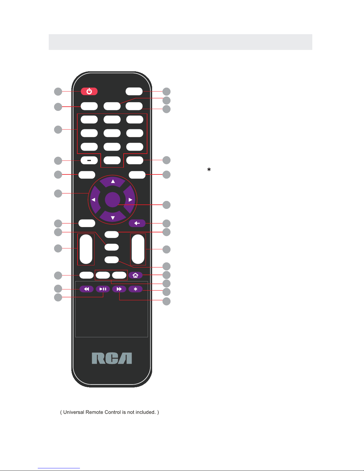
CONTROL REFERENCE GUIDE
REMOTE CONTROL
Universal Remote Code: 1218
1.STANDBY
To switch on the TV or make the TV into
standby mode.
2.SOURCE
Press this button to select an input source.
3.Picture
Selects various preset picture settings.
4.Sound
Selects various preset sound settings.
5.MUTE
Press this button to mute or restore sound.
6.0-9
Allows you to change the channel of the TV.
7.Inserts the dash for selecting digital channels directly.
8.R
Returns to the previous channel.
9.EPG
10.Info
Shows the display info.
11.UP/DOWN/LEFT/RIGHT
Moves the cursor upward/downward/to the left/to the right
when making a selection.
12.ENTER
Press to confirm selections on a menu screen.
13.MENU
Displays the OSD Menu of the TV.
14.Exit
Press this button to exit the on screen display.
15.MTS
To change among STEREO, MONO and SAP. If there is no
second language available for the signal received, LED
Display audio will output to mono.
16.CC
Press the button to enter into the CC mode.
17.SLEEP
To select the amount of time before your TV turns
Off automatically.
18.VOL+/VOLIncreases/Decreases the Volume control.
CH+/CH-
Skips to the next/previous channel on TV mode.
Press this button to select the electronic programme
guide in DTV mode.
19.
20. FAV
Press this button to show the favourite list.
21.FAV+/FAVPress this button to go through the FAV channel list.
Source
ENTER
+
_
VOL
+
_
CH
Sleep
CC
MTS
Info
Exit
Menu
EPG
4
5
6
7
0
R
Picture
Sound
Fav
Source
Mode
Standby
MHL
Vol
Vol
+
Fav
+
Fav
_
Mute
123
89
1
2
3
4
5
6
7
8
9
10
11
12
13
14
15
16
17
18
19
20
21
22
23
24
25
26
4
CONTROL REFERENCE GUIDE
REMOTE CONTROL
22.MHL
This button selects the source HDMI2 for MHL
connection or regular HDMI connection. The button
while using a ROKU™ product will return any current
running program back to the ROKU™ home screen.
23.REWIND
Under ROKU™ this button rewinds the current video
being played.
24.PLAY/PAUSE
Under ROKU™ this button plays or pauses the current
video being played.
25.FAST FORWARD
Under ROKU™ this button plays the current video at a
faster pace.
26.STAR( )
Under ROKU™ this button gives the info ROKU™ stick.
Universal Remote Code: 1218
Source
ENTER
+
_
VOL
+
_
CH
Sleep
CC
MTS
Info
Exit
Menu
EPG
4
5
6
7
0
R
Picture
Sound
Fav
Source
Mode
Standby
MHL
Vol
Vol
+
Fav
+
Fav
_
Mute
123
89
1
2
3
4
5
6
7
8
9
10
11
12
13
14
15
16
17
18
19
20
21
22
23
24
25
26
5
CONTROL REFERENCE GUIDE
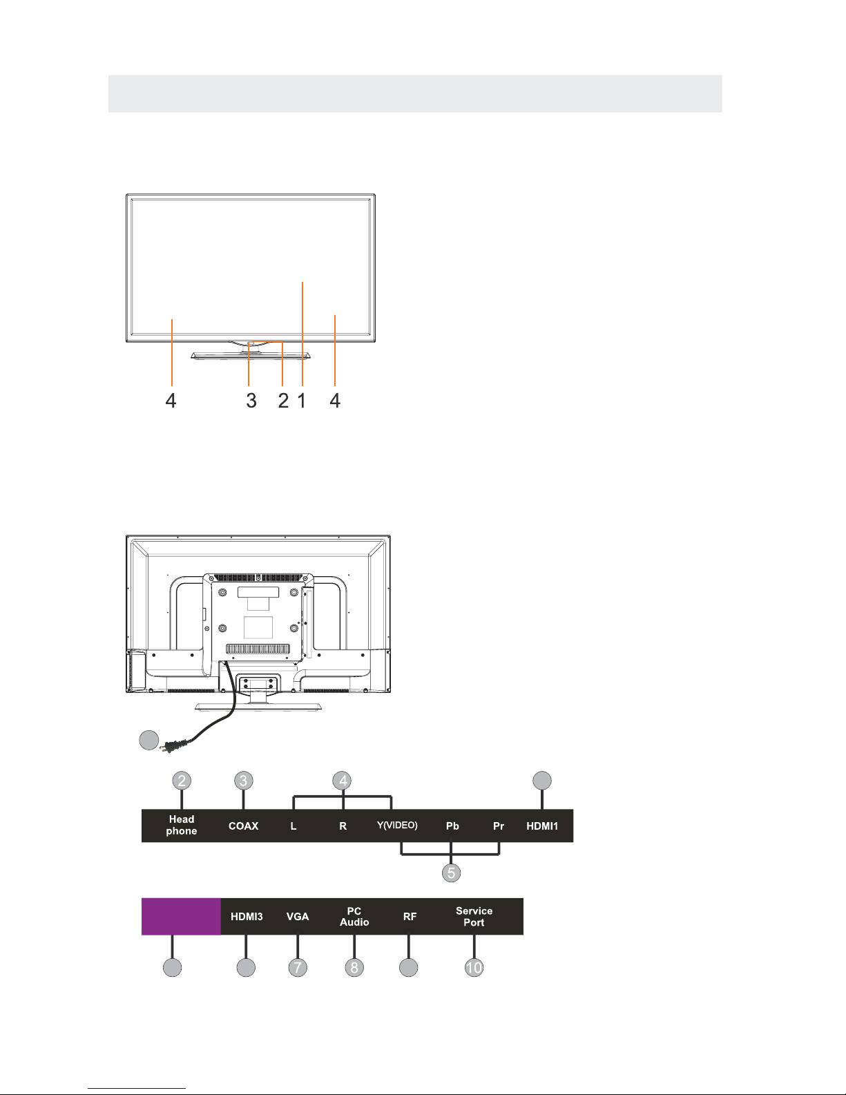
FRONT VIEW
BACK VIEW
1.Color Screen
2.Remote Sensor
Do not block this sensor or the
remote control will not work.
3.Standby Indicator
Indicates whether the unit is ON
or in STANDBY (OFF) mode.
Light in red: The unit is in STANDBY.
Light in
blue
:The unit is turned ON.
4. Speakers
6
66
9
1.Power Cor
2.Headphone Jack
3.Coax OUT Jack
4.AV IN Jack
5.COMPONENT IN Jack
6.HDMI IN Jacks
7.VGA IN Jack
8.PC ADUIO IN Jack
9.TV ANTENNA Terminal
10.Service Port
d
HDMI2 also doubles as the MHL connection for cell
phones. MHL is a protocol where the TV will display
what your cell phone displays. If your cell phone
supports MHL you can purchase a MHL cable from
any electronic store and connect it to HDMI2 and also
your cell phone. Make sure the TV's source is
changed to HDMI2 and turn on your cell phone.You
should see an image of your cell phone screen.
HDMI2 also supports ROKU™ streaming stick.
Plug the ROKU stick to HDMI2, and switch your
source to HDMI2. Afterwards use the purple
colored buttons to access ROKU functions.
1
HDMI2/MHL
6
CONTROL REFERENCE GUIDE
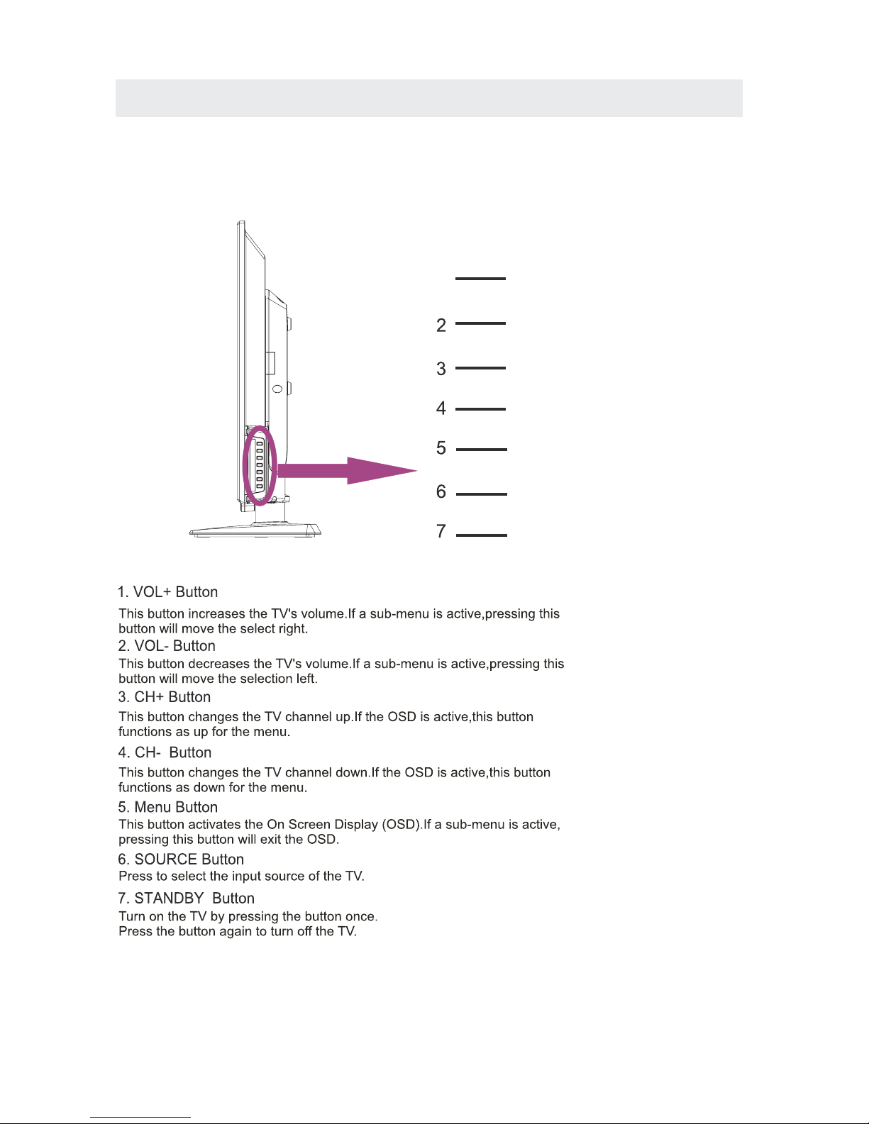
SIDE VIEW
1
VOL+
VOL-
CH+
CH-
MENU
SOURCE
STANDBY
7
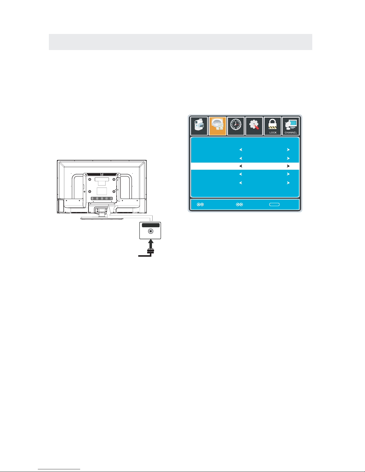
CONNECTIONS
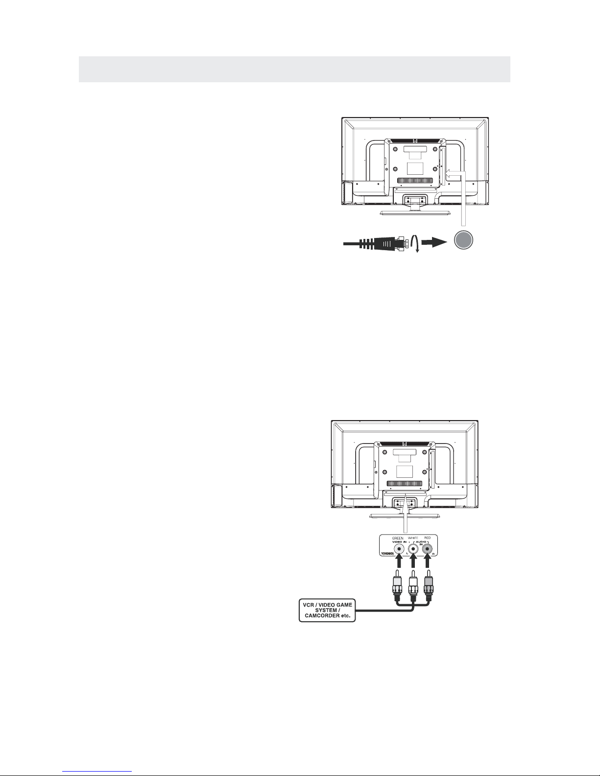
CONNECTING A TV ANTENNA / CABLE / SATELLITE
To view television channels correctly, a signal must
be received from one of the following sources:
- An indoor or outdoor aerial antenna
- A cable system
- A satellite system
For receiving over-the-air TV broadcasts, we
recommend that you use an external fixed antenna.
Should you require the use of a temporary antenna,
please ensure that you purchase an antenna with
sufficient ability to receive in weak signal areas.
Only when you are in close proximity to a transmitter
will a temporary antenna reproduce a signal as
strongly as a fixed antenna.
To connect to other equipment such as a VCR, camcorder, satellite system or cable, etc.
CONNECTING AN A/V DEVICE
NOTE
CONNECTING DEVICES WITH A COMPOSITE
VIDEO OUTPUT
Connecting to a VCR / Video Game System / Camcorder
AUDIO VIDEO OUT
NOTE
To connect A/V devices such as a VCR, video game system or camcorder.
Connect the AUDIO / VIDEO cable (not included) as shown.
Make sure you connect the cable from the other equipment ( and ) to this unit
1P. lease refer to the user manual.
for the other equipment for
more information.
Satellite, cable or TV antenna
cable to TV ANTENNA
terminal (cable not included)
(AV in)
2. Composite video input
(shared with component)
To AUD IO / VIDEO
IN jacks
To AUD IO / VIDEO
OUT jacks
8
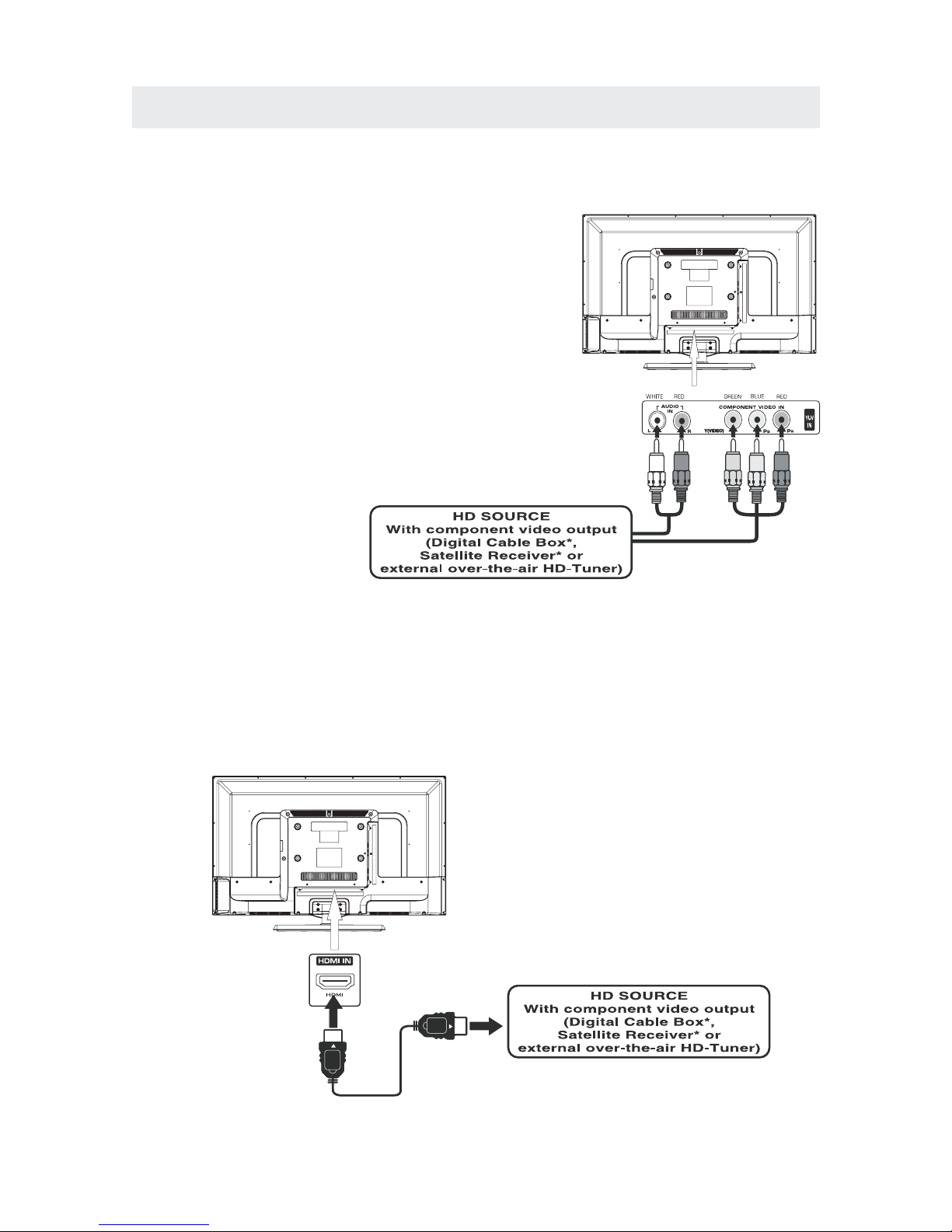
CONNECTIONS
CONNECTING A HIGH-DEFINITION (HD) SOURCE USING CONNECTION
NOTE
COMPONENT
High-Definition (HD) Devices with component video output must be connected to the Y input.
Connect the component video cable and audio cable (not included) as shown.
Make sure you connect the component video cable and audio cable from t he ot her e qui pme nt
When connecting a DVD player to the television,
the picture resolution is solely dependent upon
the resolution supported by the DVD player attached.
DVD player resolutions vary from 480i to 1080i.
and this televisi on can su ppor t DVD play ers up to
a maximum resolution of 1080i.
PbPr
* May require a subscription
for receiving HD channels,
check with your cable/satellite
service provider for details.
To COMPONENT
VIDEO OUT jacks
CONNECTING A HIGH-DEFINITION (HD) SOURCE USING HDMI CONNECTION
HDMI (High Definition Multimedia Interface) supports both video and audio on a single digital connection
for use with DVD players, DTV, set-top boxes and other digital AV devices. HDMI was developed to provide
the technologies of High Bandwidth Digital Content Protection (HDCP) as well as Digital Visual Interface
(DVI) in one specification. HDCP is used to protect digital content transmitted and received by
DVI-compliant or HDMIcompliant displays.
HDMI has the capability to support standard, enhanced or high-definition video plus standard to
multi-channel surround-sound audio. HDMI features include uncompressed digital video, a bandwidth of
up to 2.2 gigabytes per second (with HDTV signals), one connector (instead of several cables and
connectors), and communication between the AV source and AV devices such as DTVs.
To HDMI
IN jack
To HDMI
jackOUT
To COMPONENT
VIDEO IN jacks
AUDIO IN jacks
To COMPONENT AUDIO
OUT jacks
Connect the HDMI cable (not included) as
shown:
Make sure you connect the cable from the
source equipment ( ) to this unit
().
HDMI OUT
HDMI IN
HDMI CABLE
(NOT INCLUDED)
(COMPONENT OUT and AUDIO OUT)to the unit COMPONENT IN.
COMPONENT IN
To COMPONENT
9
CONNECTIONS
CONNECTING A
AUDIO - PC OUT
VGA AUDI O - PC IN
PC
VGA
Connect the 15-pin D-SUB PC/VGA connector
from your computer to the 15-pin D-SUB PC/VGA
input on this unit using a monitor cable and an
audio cable (not included) as shown.
Make sure you connect the cable from the computer
( and ) to this unit
(and ).
TO PC Connector
TO AUDIO OUT jacks
NOTE
•Insert the pow er plug fully in to the socket outlet
If the po wer plug is loos e it could generate heat and
cause fir e
Do not touch the power plug with a wet hand
This may cause electrical shock
Do not us e any power cord ot her than that provided
with this TVThis may cause fire or electrical shock
Do not damage the power cord
A damaged cord may cause fire or electrical shock
•Do not move the TV wit h the co rd plugged in the
socket outlet.
•Do not place a heavy object on the cord or
place
the cor d near a high-temperature object.
•Do not twist the cord, bend it excessively, or stretch it.
•Do not pull on the cor d. Hold onto the power plug body when disconnecting cord.
•Do not use a damaged power plug or socket outlet.
.
(,
.)
.
.
•
•
•
connected to prevent electrical shock.
Ensure that the power plug is easily accessible.
Ensure the earth pin on the power plug is securely
•
•
.)
10
CONNECTIONS
Connection to a Home Theater Audio System
For BEST audio performance
Connecting to a Home Theater System
Dolby Digital can deliver optimal 2 channel
stereo or surround sound with five discrete
full range channels plus a sixth channel for
a subwoofer.
Enjoy optimal sound reproduction from your
system with a Dolby Digital amplifier that
incorporates a digital coaxial input. Connect
an optional digital cable directly to the
television’s Coax audio output to listen
through all inputs except VGA.
(The VGA does not support digital audio)
How To Setup Digital Output
Press the MENU button on the remote control
Press the right ► arrow button to select sound
Press the down ▼ arrow button to highlight
SPDIF type right ► Raw or PCM
Coax
SPDIF OUT
Setup
12
6
Time
Equalizer Settings
MTS
Audio Language
AVL
Surround Sound
Move Select Exit
MENU
Off
Picture
Sound
English
Digital Audio Output
PCM
Off
Stereo
11
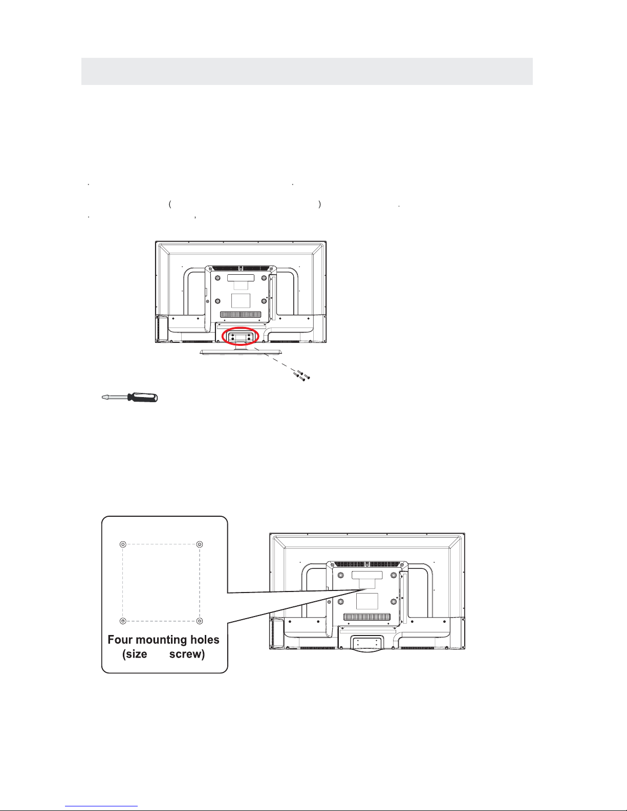
WALL MOUNT INSTALLATION
INSTALLING REMOVING THE BA SE STAND
WARNING/:The
LED D
isplay is very fragile and must be protected at all times when removing the base
Stand
Be sur e that no hard or sharp object or anything that could scr atch or damage the LED display comes into
contact with it Do NOT exert pressure on the front of the unit at any time because the screen could crack
1 Disconnect all cabl es or cords connected to the unit
2Lay the unit down on a flat surface with the back side facing up Please make sure to place a soft
cushioned material such as a pillow or thick piece of foam beneath t he s cr ee n
3To remove the base stand loosen screws off the holes then pull downwards to release
the base stand
,
.
. .
. .
MO UNTING ON THE WALL
NOTE
Remove th e base stand befo re mou nti ng the unit on th e wall .
This unit is VESA-compliant, and is designed to be wall-mounted with a VESA-compliant 8”x4 ”
(200mm x 100mm) mounting kit designed for flat-panel TVs ( not supplied). Mount this unit according t o
the instructions included in the mounting kit.
Length of screw should not exceed 8 mm.
8”
4”
M6
12
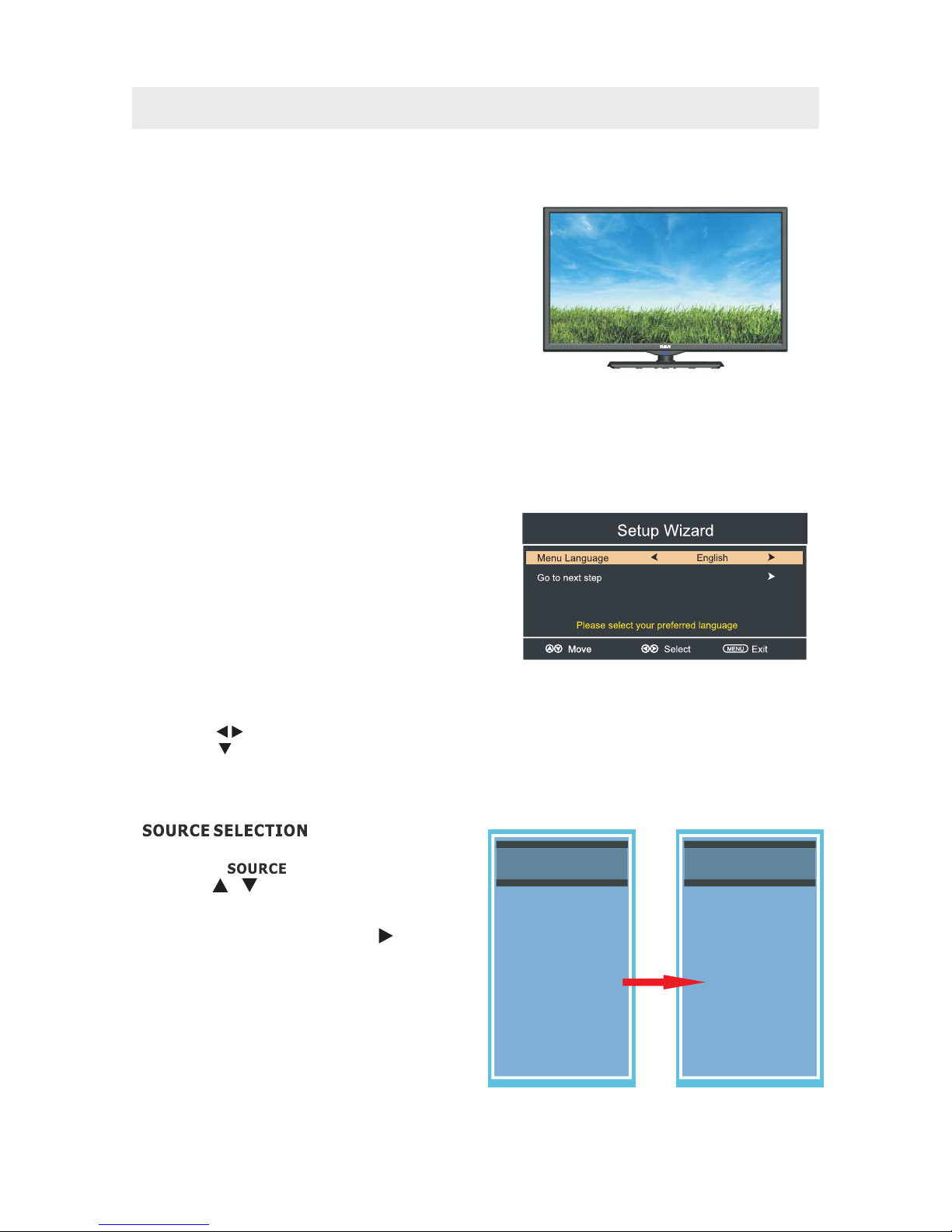
INITIAL SETUP
When you turn on your television set for
the first time, be sure to place it on a solid
stable surface.
To avoid danger, do not expose the TV
to water, or a heat source
(e.g. lamp, candle, radiator).
Do not obstruct the ventilation grid
at the rear and be sure to leave sufficient
gaps around the unit.
PUTTING THE UNIT ON A PROPER PLACE
TURNING THE UNIT ON FOR THE FIRST TIME
After you have initially connected your TV
antenna or cable,
turn the television ON.
A screen will display asking you to run a
to search and receive
available local digital channels.
It is he re where you will se lect antenna option s
and run .
Channels will be stored in the TV tuner.
Press the button on the remote control.
Press the button to highlight AIR/CABLE.
Channel Auto Scan
Channel Auto Scan
MENU
Using the buttons, scroll to highlight chaneel mode.
1. Pre ss the button on the rem ote contro l.
2.
and select any of them using the button or
the button.
ource
Note:
Before watching please make sure all necessary
cables and devices are connected.
ENTER
Us e or butt on to select the op tion sthe
(The screen will change to your desired s ).
(TV,YPbPr/ , HDMI1,HDMI2/MHL,HDMI3,PC)AV
Source Select
TV
YPbPr/AV
HDMI1
HDMI2/MHL
HDMI3
PC
Source Select
TV
YPbPr/AV
HDMI1
ROKU
HDMI3
PC
13
TV SETUP
Press MENU button to display the main menu.
Press ◄ / ► button to select CHANNEL in the main menu,it will highlight the first option.
Setup
LOCK
12
6
Time
Picture
Sound
CHANNEL
Air/Cable
Auto Scan
Fa vorite
Show H ide
Ch anne l Numbe r
Ch ann el lab el
Ch anne l List
Air
Select ExitMove
MENU
Move
MENU
AIR / CABLE
This feature allows you to switch between air (such as using antenna) and cable.
AUTO SCAN
This feature searches channels automatically for you.
FAVORITE
This feature gives the favorite list of channels added by you.
CHANNEL LIST
This feature shows the list of stored channels.
SHOW / HIDE
This feature tells you if you have chosen for channel to be skipped.
CHANNEL NUMBER
This feature tells you what channel you are currently on.
CHANNEL LABEL
This feature changes the name of the channel.
Please Note:
The channel options are only available when you select TV as your SOURCE.
When you open the OSD menu on other sources (HDMI, YPbPr/AV, PC) these
options will be grayed out.
CHANNEL MENU
14
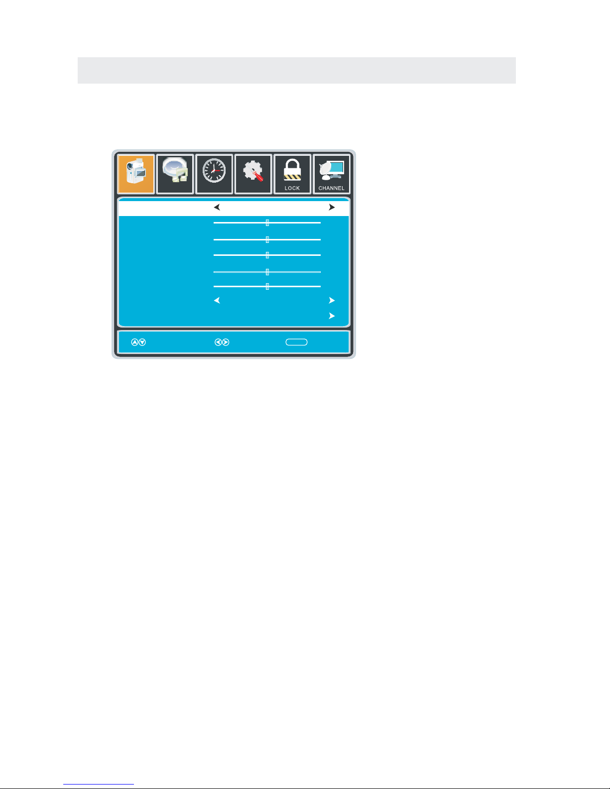
TV SETUP
Press MENU button to display the main menu.
Press ◄ / ► button to select PICTURE in the main menu,it will highlight the first option.
PICTURE MODE
This feature changes various color modes for the TV.
BRIGHTNESS
This feature changes the picture's detail in dark colors.
CONTRAST
This feature changes the difference between dark and bright objects.
COLOR
This feature changes the amount of color in the picture.
TINT
This feature changes the white balance of the color.
SHARPNESS
This feature changes the picture quality.
COLOR TEMPERATURE
This feature adjusts the color temperature of the TV, giving warm, normal,
cool.
ADVANCED SETTINGS
a)ASPECT RATIO This feature changes the various aspects of the TV's video.
(Aspects include wide, zoom, cinema,normal).
b)NOISE REDUCTION This feature reduces general pixilation by blurring them.
c)DYNAMIC CONTRAST This feature allows the TV to automatically adjust the contrast of the
TV depending on the picture you are viewing.
PICTURE MENU
Setup
12
6
Time
Picture
Sound
Picture Mode
Contrast
Brightness
Color
Tint
Sharpness
Color Temperature
Standard
Normal
Move Select Exit
MENU
50
50
50
0
50
Advanced Settings
15
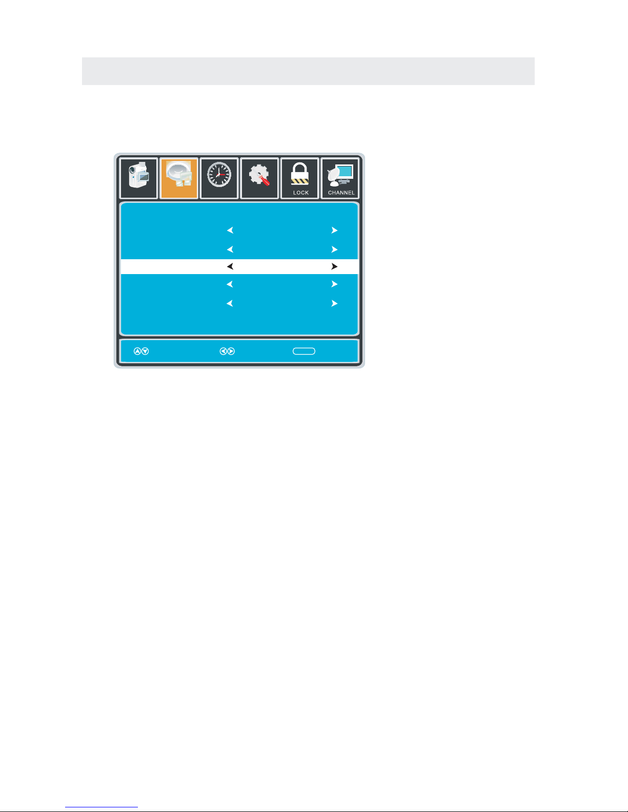
TV SETUP
Press MENU button to display the main menu.
Press ◄ / ►button to select SOUND in the main menu,it will highlight the first option.
EQUALIZER SETTINGS
This feature enables the internal equalizer of the speakers.
You can adjust the settings individually or use the presets (standard, music, movie, sports, user).
MTS
This feature adjusts the second audio programming in analog channels.
AUDIO LANGUAGE
This feature adjusts the digital second audio programming in digital channels.
DIGITAL AUDIO OUTPUT
This feature adjusts the digital audio output.
SURROUND SOUND
This feature adjusts the dimensional surround effect on or off (for built-in speakers only).
AVL
This feature adjusts the auto volume leveler enabling volume protection from overly loud
commercials.
SOUND MENU
Setup
12
6
Time
Equalizer Settings
MTS
Audio Language
AVL
Surround Sound
Move Select Exit
MENU
Off
Picture
Sound
English
Digital Audio Output
PCM
Off
Stereo
Please Note:
AUDIO LANGUAGE and MTS are dependent on the broadcasting station's support and are only
available under the source TV.
16
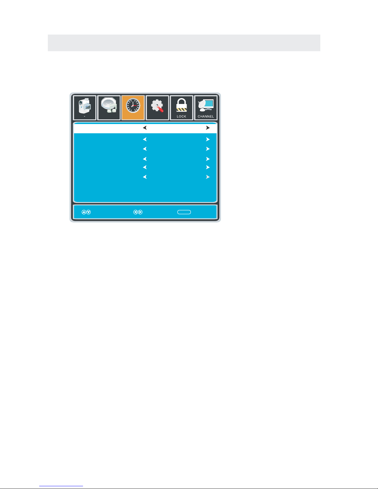
TV SETUP
Press MENU button to display the main menu.
Press ◄ / ►button to select TIME in the main menu,it will highlight the first option.
TIME MENU
Setup
Sleep Timer
Time Zone
Daylight Saving Time
Clock
Mo ve S ele ct Exit
MENU
Picture
Off
Pacific
Off
2013/01/01 12:00 AM
12
6
Time
Sound
Time Format
12-hour
Auto Clock On
SLEEP TIMER
This timer automatically turns off the TV at the designated time.
TIME ZONE
This option adjusts the global time zone for the TV.
DAYLIGHT SAVING TIME
This option toggles the daylight saving time feature.
TIME FORMAT
This option adjusts the display format for the time.
AUTO CLOCK
This option enables the TV to sync time with the antenna.
(Put it on AUTO if you have an antenna attached to the TV.If you have CABLE or SATELLITE or
anything else please use make sure AUTO CLOCK is turned off)
CLOCK
This option adjusts the time and date of the TV.You need to disable AUTO CLOCK in order to
use this function.
Please Note:
The TIME function will only keep accurate time if the TV is plugged into a power source.
If the TV is unplugged or the power strip is turned off, the TV's time will not be accurate.
17
TV SETUP
Press MENU button to display the main menu.
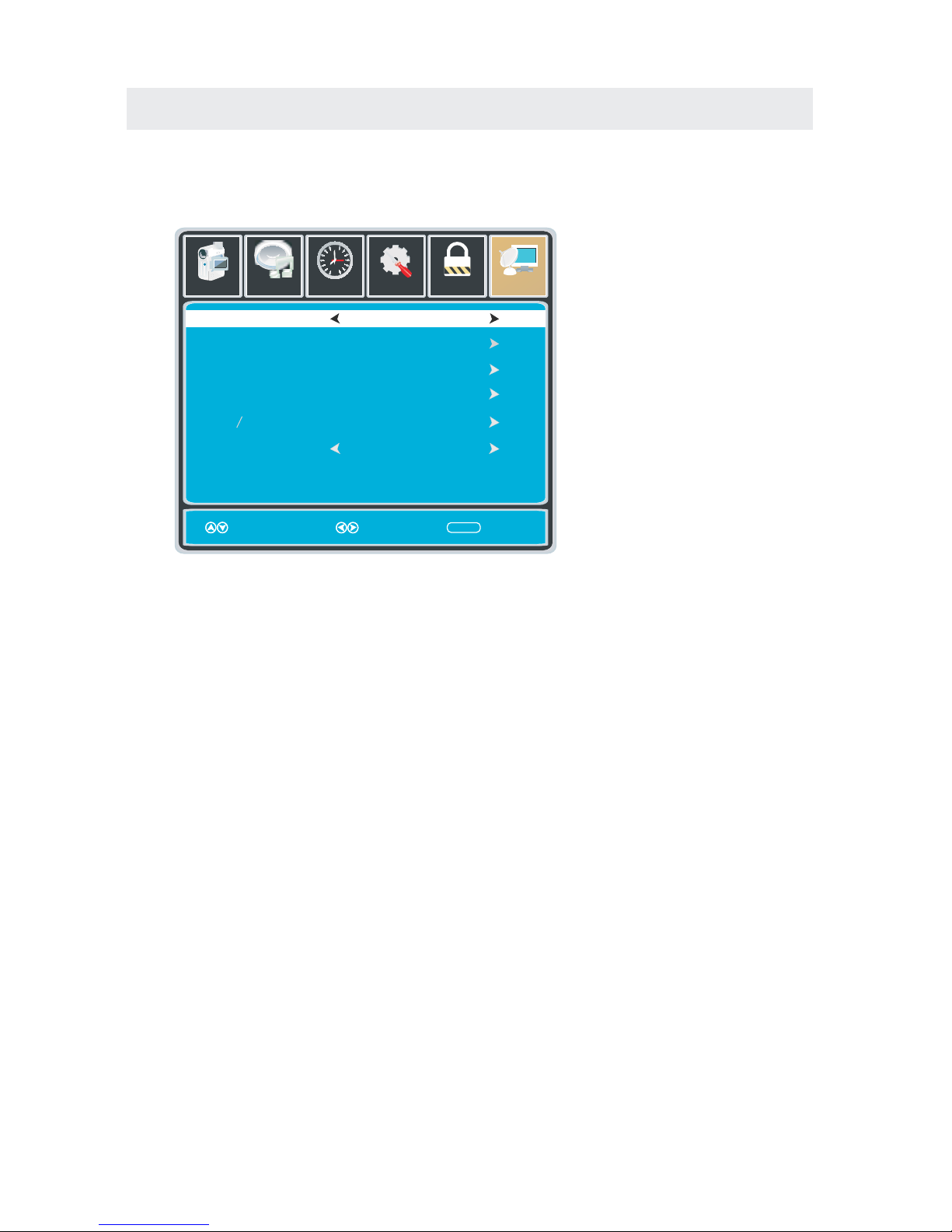
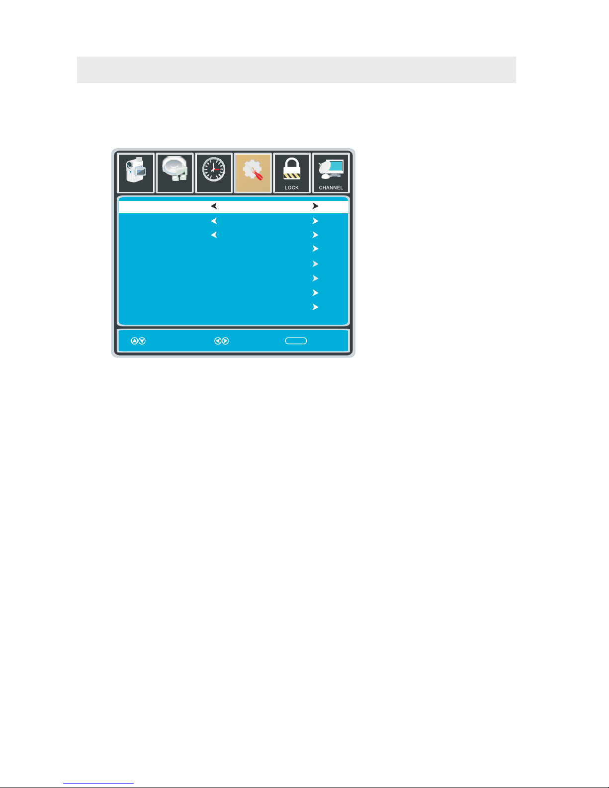
Press ◄ / ► button to select SETUP in the main menu,it will highlight the first option.
SETUP MENU
Lock
12
6
Time
Channel
Menu Language
Transparency
Zoom Mode
Noise Reduction
Advance
Close Caption
XVS
Restore Default
English
Mo ve Select Ex it
MENU
Picture
Off
Normal
Setup
Audio
On
12
6
Time
Menu Language
Transparent
OSD Timeout
Closed Caption
Input label
Ot her S ett ing s
Setup Wizard
Restore Default
English
Mo ve Select Exit
MENU
Picture
25%
30 S ec.
Setup
Sound
MENU LANGUAGE
This option changes the language of the TV's OSD menu.
TRANSPARENT
This option changes the transparency of the menu allowing background TV images to show through.
OSD TIMEOUT
This option changes the time which the TV's OSD menu automatically goes off.
CLOSED CAPTION
This option displays words on the TV.
INPUT LABEL
This option changes the source names to your personal preference.
OTHER SETTINGS
This option adjusts miscellaneous options of the TV.
AUDIO ONLY-This option turns off the screen while the audio is still playing.
RESTORE DEFAULT
This option restores all the changes in the OSD menu back to the default factory settings.
SETUP WIZARD
This option enables the TV to show you the setup wizard of the TV again.
Please Note:
Closed captioning is only available under AV and TV ports.
Closed captioning depends on your TV program's support. Sometimes due to the TV channel
or the signal, closed captioning will not be available.
In United States, closed captioning under analog signals is CC1.
In United States, closed captioning under digital signal is Service1.
18
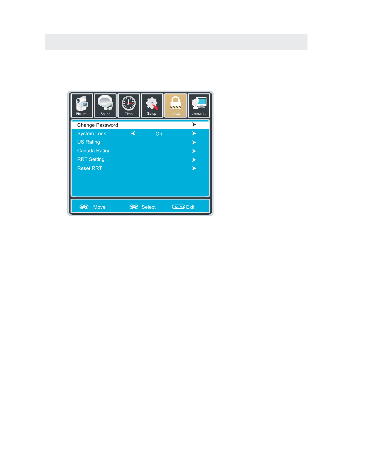
TV SETUP
Press MENU button to display the main menu.
Press ◄ / ► button to select LOCK in the main menu,it will highlight the first option.
Press “0000” for the lock password.
LOCK MENU
CHANGE PASSWORD
This option allows you to change the LOCK menu password.
SYSTEM LOCK
This option enables parental locking and filtering for the TV.
US RATING
This option filters US TV programming and movies.
CANADA RATING
This option filters CANADA TV ratings.
RRT SETTING
This feature is a downloadable rating filter based on TV broadcasts. With the transition of TV
broadcasts to digital, future changes, and enhancements in how TV shows are rated for content
are possible.
RESET RRT
This option resets the RRT5 settings.
Please Note:
Please refer to RATINGS EXPLAINED for more information on ratings definitions.
Downloadable rating and clear downloadable data might be grayed out depending on the Tvs
tations support.
RRT5 options are based on TV broadcasts, if it is grayed out, then it is not available in your region.
12
6
19

Hi!
Let’s get started.
20
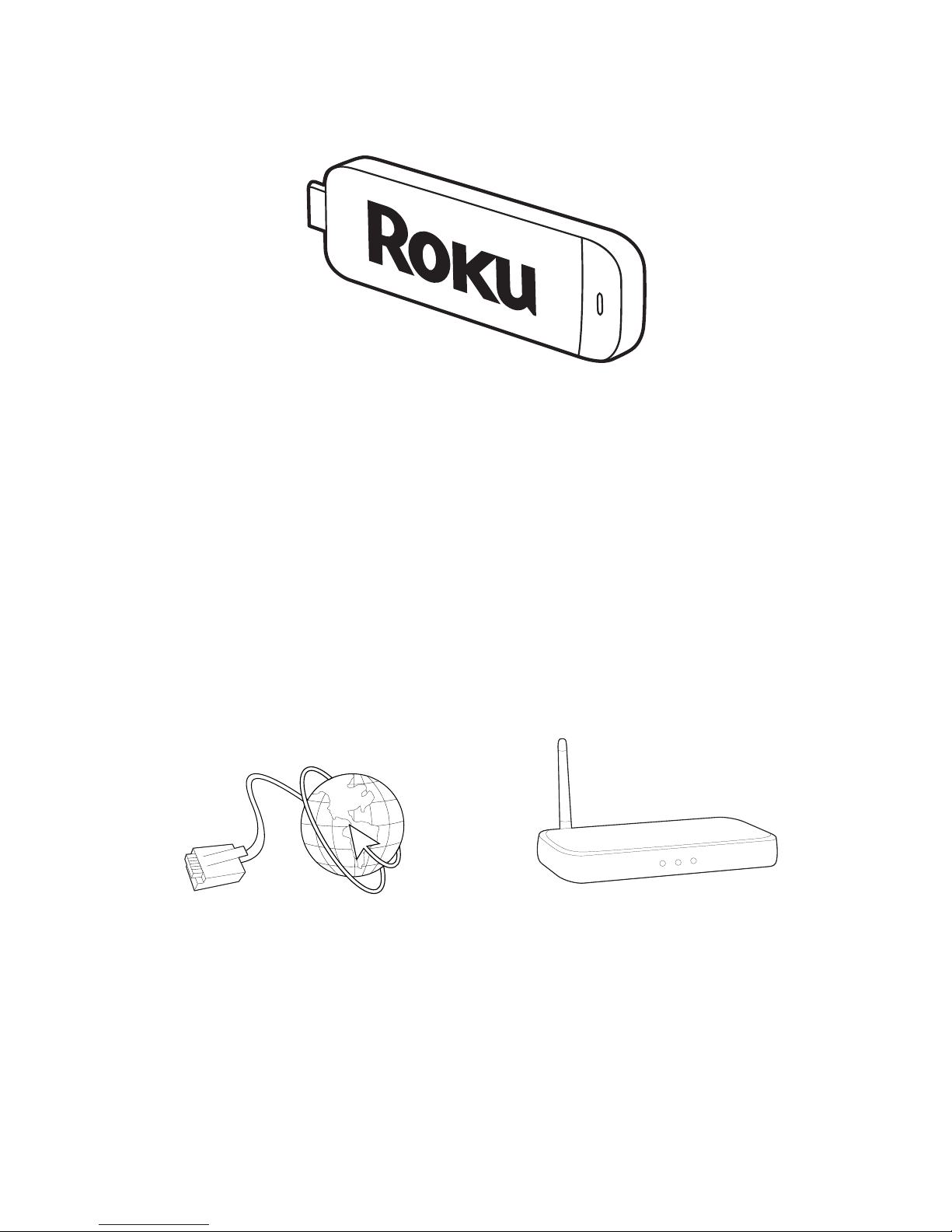
Roku Streaming Stick
TM
High speed
Internet
What you need
Wireless Router
21
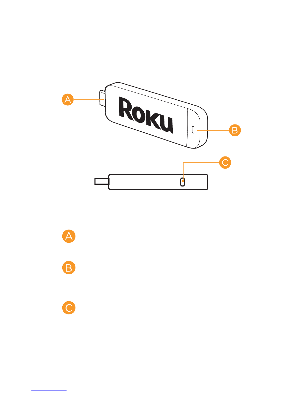
Know your
Streaming Stick
[MHL CONNECTOR] Plugs into the
MHL port on the back of your TV.
[STATUS LIGHT] Signifies it is on
when lit, or activity when flashing.
[RESET BUTTON] Used to reset
your Streaming Stick
22
 Loading...