

RCA RLED3265A, RLED3264A, RLCD5092A Operating Instructions Manual
46" 1080p LED Television
RLED4664A

1
Contents
Contents
Caution
Safety Information
Unit and Accessories
Product Feature
Introduction
1. Front View
2. Rear View
4. Remote Control
Basic Operation
OSD Menu
1. Picture menu
2. Sound menu
3. Channel menu
4. Parental Control menu
5. Setup menu
6. Others menu
Simple Troubleshooting
2
3
4
4
5-9
5
6
8-9
10
11-18
11-12
13
14
15-16
17
18
19
20
3. Instruction for Wall Mount 7
2
Caution
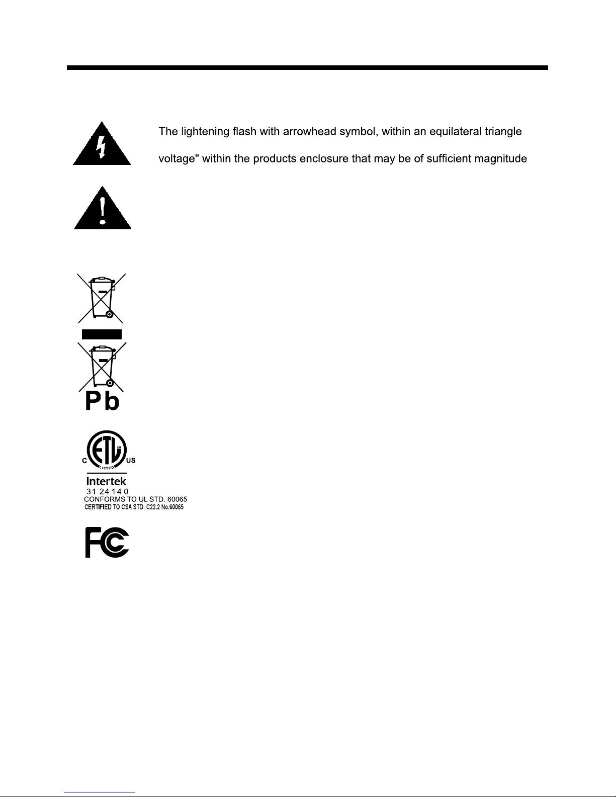
Caution
is intended to alert the user to the presence of un-insulated "dangerous
to constitute a risk of electric shock to the persons.
The exclamation point within an equilateral triangle is intend to alert the
user to the presence of important operating and maintenance (servicing)
instructions in the literature accompanying the appliance.
Correct disposal of this Product
(Waste Electrical & Electronic Equipment (WEEE)
Your product is designed and manufactured with high quality materials and
components which can be recycled and reused.
This symbol means that electrical and electronic equipment, at their endof-life should be disposed of separately from your household waste.
Please dispose of this equipment at your local community waste collection/
recycling centre.
In the USA there are separate collection systems for used electrical and
electronic products. Please help us to conserve the environment we live
in!
This unit complies with America Safety directives.
This unit complies with FCC directives.
3
Safety Information
Safety Information
Electrical safety
Physical safety
the power cable
4
Unit and Accessories and Product Feature
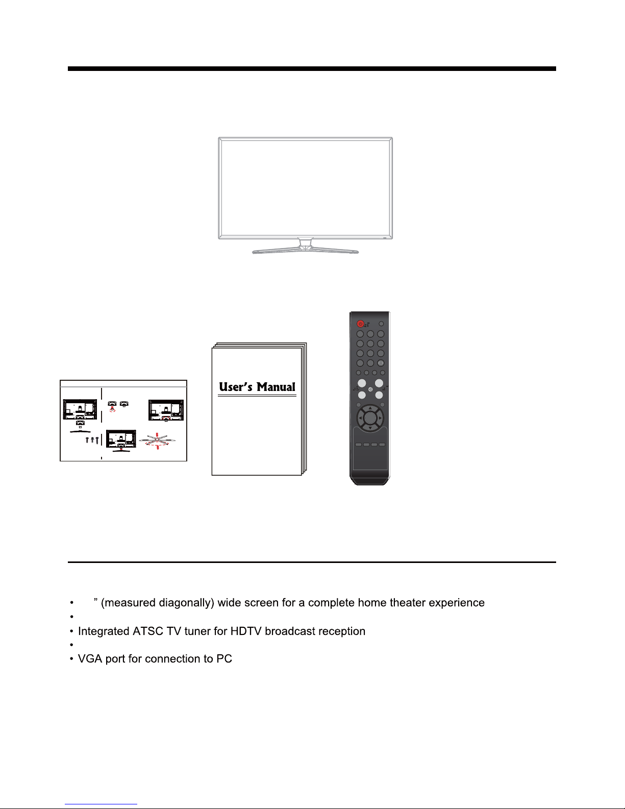
Unit and Accessories
TV set
User's Manual
Remote Control and
Batteries (AAA x2)
Product Feature
PICTURE SOUND SLEEP DISPLAY
INPUT
VOL+
VOL-
EXIT
MUTE
MENU
OK
CH+
CH-
123
456
789
0 -/--
FAV
CC EPG
MTS
46
Three HDMI inputs for true digital connections
HDMI is a trademark of HDMI Licensing LLC in the United States and other countries.
Stand Installation Guide
®
1920 x 1080 native resolution for Full-HD(1080p) performance
Instructions for fixing TV stand
The parts
Installation
Screws
˄three specifications˅
(There are four parts for installing stand)
1. Put the stand neck on the stand rear
board, fix the stand neck with 4 pieces of
3. Put stand on the stand rear cabinet, fix the
stand with four pieces of screws(B4*24)
Note: the pictures below are only for reference
1.TV
2.stand rear board
3.stand neck
4.stand base
2.screws with mat pieces (M4*12),pictures2
1.screws (B4*16),picture1
3.the longest screws (B4*24).pictures3
1.The panel is facing
downwards
2. The two longer stand
legs are downwards,
3. Fix with 4 pieces of screws,
picture1
picture2
picture3
screws (B4*16).
And fix the inner of stand neck
with 4 pieces of screws.
2. Put the stand rear board on the rear
cabinet ofTV. fix the rear board with
4 pieces of screws(M4*12).
MENU
CH+
CH-
VOL+ VOL- POWER
INPUT
5
Introduction
Introduction
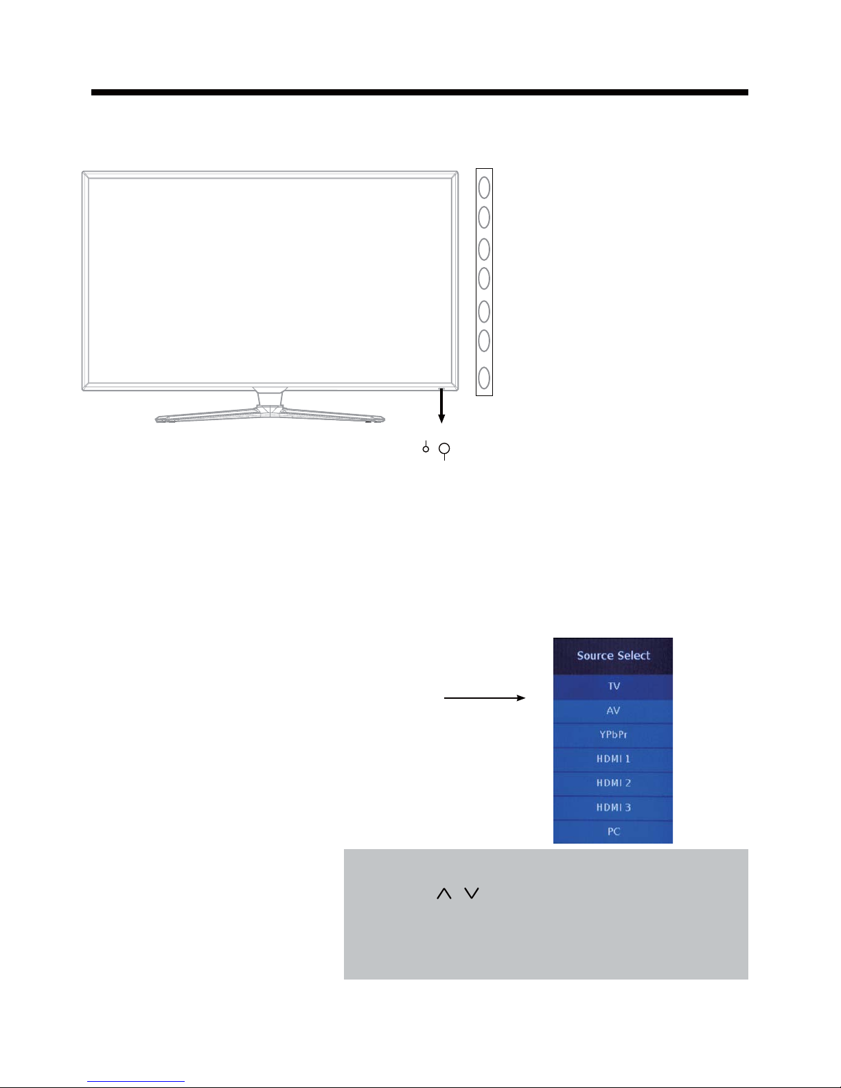
1. Front View
1). (IR) Infrared Receiver: Receives IR signals from the remote control.
(Power on/Standby)LED Indicator: Press POWER to turn on and off.
Indicator on(Red) Standby mode
Indicator on(Green) Power on mode
2). The functions of the buttons:
INPUT: Press to display the input source menu.
MENU: Press to display the OSD menu,
press again to exit the menu.
CH+/-: Press to scan through channels.
VOL+/-: Press to adjust the volume.
POWER: Turn on/standby the TV set.
The effective receiving range for the signal is 5-8 metres from the front of the remote
control window, and 30
0
to the left or right side and 200 above or below the remote control
window.
Press INPUT button on the TV set or remote control to
display the input source menu, and use CH+/- button on
the TV set or
/ button on remote control to select the
input source, press OK button on the remote control to
enter.
Note: Before you select the input source, make sure the
connections are prepared.
Power Indicator
Remote Control window
(Keep clear)
6
Introduction
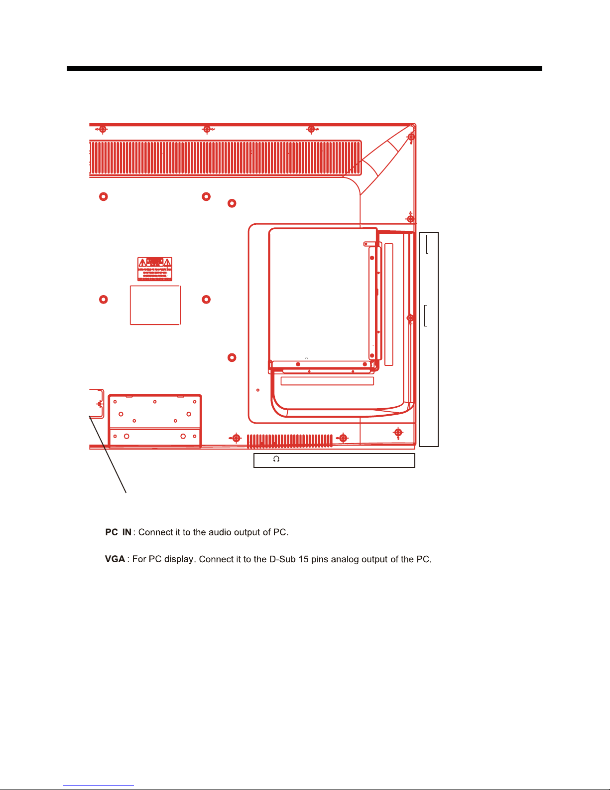
2. Rear View
2). Headphone out
: Connect it to your headphone or audio equipments.
5).
4).
RF
: Connect antenna or cable 75 Ohm coaxial to receive TV signal.
7).
COAX : Digital audio output.
10).
YPbPr : Connect them to the component video output of video device.
: Connect it to the HDMI output of video device.
6).
HDMI1/2/3
L/R in
: Connect them to audio output of video device (shared with YPbPr).
11).
L/R out
: Connect them to audio equipments.
VIDEO : Connect it to video output of video device.
9).
8). Service
: For service use only.
AC POWER IN:
Connect to an earth 100-240V~ 50/60Hz outlet with the power cable.
1).
3).
RF VGA HDMI1
HDMI2
HDMI3
SERVICE
VIDEO
YPbPr
HEADPHONE OUT
PC IN
COAX
RF VGA HDMI1
HEADPHONE OUT
PC IN
R
L
R
L
Audio out
Audio in
 Loading...