

Page 1
v.1.0 (DTA800B-EN)
QuickStartGuide
www.rcaaudiovideo.com
Congratulations on purchasing your new RCA Digital TV Converter Box.
Please read these instructions for quick tips on using the unit.
DTA800
About Digital TV
Digital TV is a new broadcast system for TV stations intended to replace the analog NTSC television system in the United States.
The technical standard for Digital TV is defi ned by the Advanced Television Systems Committee (ATSC).
Digital channels
An advantage of digital TV broadcasting is that each broadcaster can now send multiple channels. For example, a broadcaster
might send the main program on channel 8-1 with a weather channel on channel 8-2. To view the weather on that station,
just press the number “8”, then the “dash” button, and then the number “2”. The standard format of digital channel numbers
consists of two groups of numbers (2-digit and 1-digit) and separated by a dash (e.g. 12-3).
Receiving digital signals
The Digital TV signal is different from the analog NTSC signal. A good signal strength is required to successfully receive and
decode Digital TV broadcasts. Unlike analog broadcasts, which may show a “fuzzy” image with a weak signal, Digital TV images
may “break up” or not display at all if the signal is too weak. If your Digital TV signal is weak, you may need to purchase a more
powerful antenna to improve reception.
In general, a simple indoor antenna connected to the DTA800 Digital TV Converter Box is suffi cient for receiving Digital TV.
However, some areas may require the use of a more powerful antenna. If you fi nd you are not receiving local stations or the
signal is weak, you should switch to a “Smart Antenna” or an outdoor antenna. The Smart Antenna is a new type of steerable
antenna without any moving parts and is highly recommended. This Converter Box is compatible for connection with a Smart
Antenna.
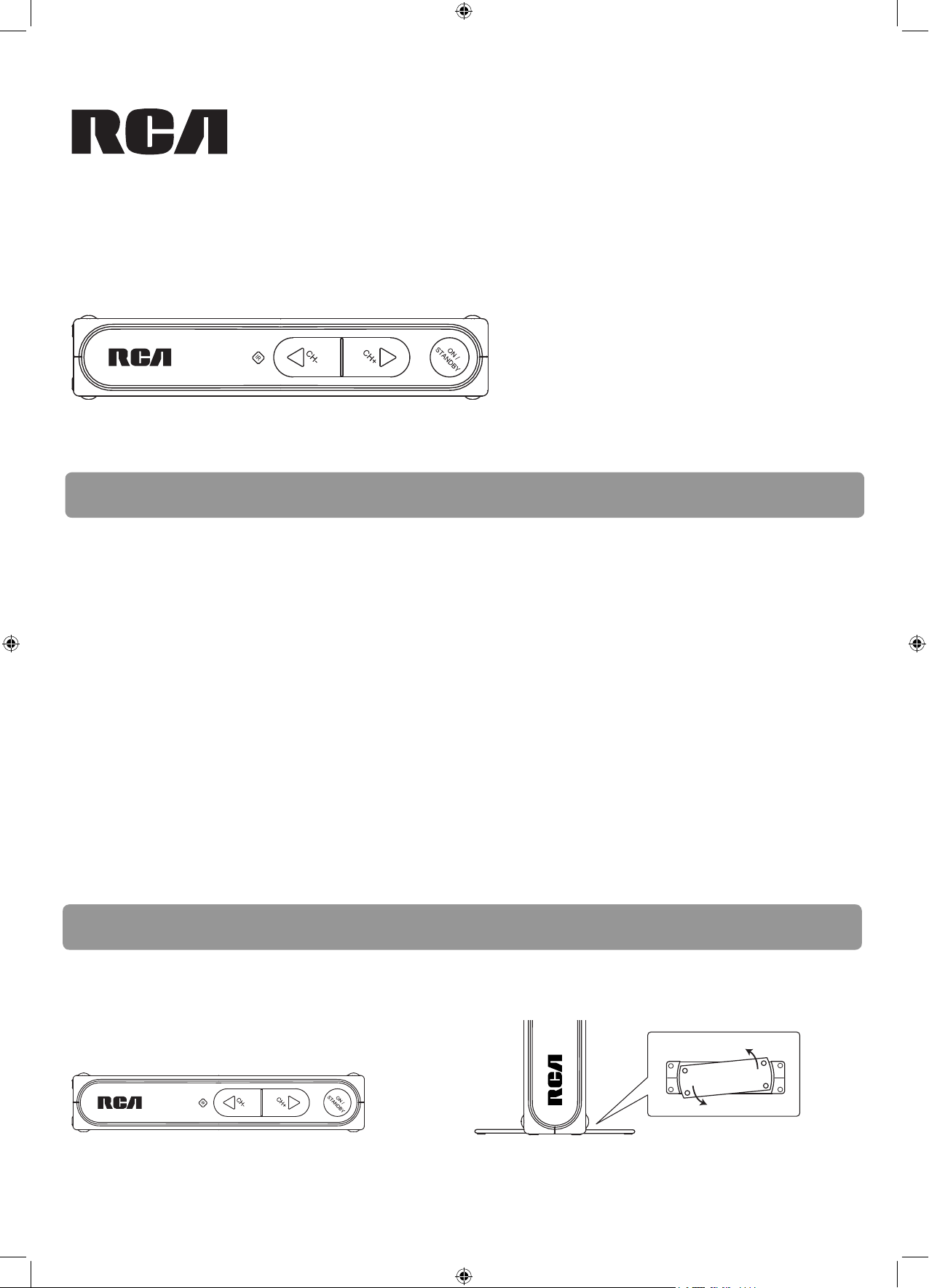
Step 1: Installation
The Converter Box can be installed either horizontally or vertically. The left side of the Converter Box can be rotated as a stand
for vertical installation.
Bottom view
Horizontal installation Vertical installation
DTA800-B
DTA800B_EN(QSG).indd 1DTA800B_EN(QSG).indd 1 12/6/07 10:59:26 AM12/6/07 10:59:26 AM
Page 2
CH4
OUTPUT
TO TV
SMART ANTENNA IN
ANTENNA IN
CH3
TV
ANTENNA
ANTENNA IN
ANTENNA OUT
CH3
CH4
VIDEO
AC~120V
R
AUDIO
L
Step 2: Connections
CH4
OUTPUT
TO TV
SMART ANTENNA IN
ANTENNA IN
AC~120V
CH3
R
AUDIO
L
TV
ANTENNA
VIDEO
CH4
OUTPUT
TO TV
SMART ANTENNA IN
ANTENNA IN
CH3
TV
AUDIO IN
L R
VIDEO IN
VIDEO
AC~120V
R
AUDIO
L
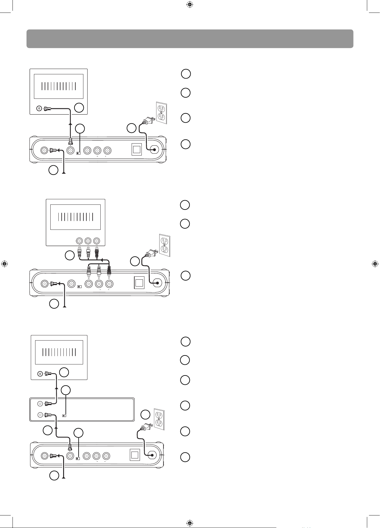
Option 1: Your TV has an antenna jack only
1
2
2
3
3
4
AC120V
60Hz
4
Connect your existing antenna cable to the ANTENNA IN jack
of the Converter Box.
Connect the RF coaxial cable (supplied) from the OUTPUT TO
TV jack of the Converter Box to the ANTENNA jack of the TV
set.
Slide the CH3/CH4 selector on the back of the Converter Box to
the channel that is not in use in your area. The Converter Box
will send its video signal to either Channel 3 or 4 on your TV.
Connect the AC power cable of the Converter Box to a
suitable wall outlet.
1
Back of the RCA converter box
From antenna
Option 2: Your TV has Audio/Video jacks (red, white & yellow connectors)
1
Connect your existing antenna cable to the ANTENNA IN jack
of the Converter Box.
2
Connect the Audio/Video cables (not supplied) from the
Audio/Video OUT jacks (yellow, white, red) of the Converter
Box to the Audio/Video IN jacks on the TV set.
If there are more than two sets of Audio/Video jacks on the
2
3
AC120V
60Hz
TV set, connect only either AV1 or AV2 input jacks to those of
the Converter Box.
3
Connect the AC power cable of the Converter Box to a
suitable wall outlet.
1
From antenna
Back of the RCA converter box
Option 3: You also need to connect your VCR
Connect your existing antenna cable to the ANTENNA IN jack
1
of the Converter Box.
Connect the RF coaxial cable* (supplied) from the OUTPUT TO TV
2
jack of the Converter Box to the ANTENNA IN jack of the VCR.
3
Connect the RF coaxial cable* (not supplied) from the
3
ANTENNA OUT jack of the VCR to the ANTENNA IN jack of the
TV set.
Slide the CH3/CH4 selector on the back of the VCR to the
4
channel that is not in use in your area. The VCR will send its
video signal to either Channel 3 or 4 on your TV.
Slide the CH3/CH4 selector on the back of the Converter Box to
5
the channel that is not being used by the VCR; e.g., if you set the
4
VCR
6
2
5
AC120V
60Hz
VCR selector to CH3, slide the Converter Box selector to CH4.
Back of the RCA converter box
1
From antenna
SMART ANTENNA IN – For connecting a Smart Antenna. Refer to the antenna’s user manual for proper connection.
Connect the AC power cable of the Converter Box to a
6
suitable wall outlet.
* You can also use Audio/Video cables (similar to option 2) if
the connection jacks are available on the VCR and TV.
DTA800B_EN(QSG).indd 2DTA800B_EN(QSG).indd 2 12/6/07 10:59:26 AM12/6/07 10:59:26 AM
Page 3
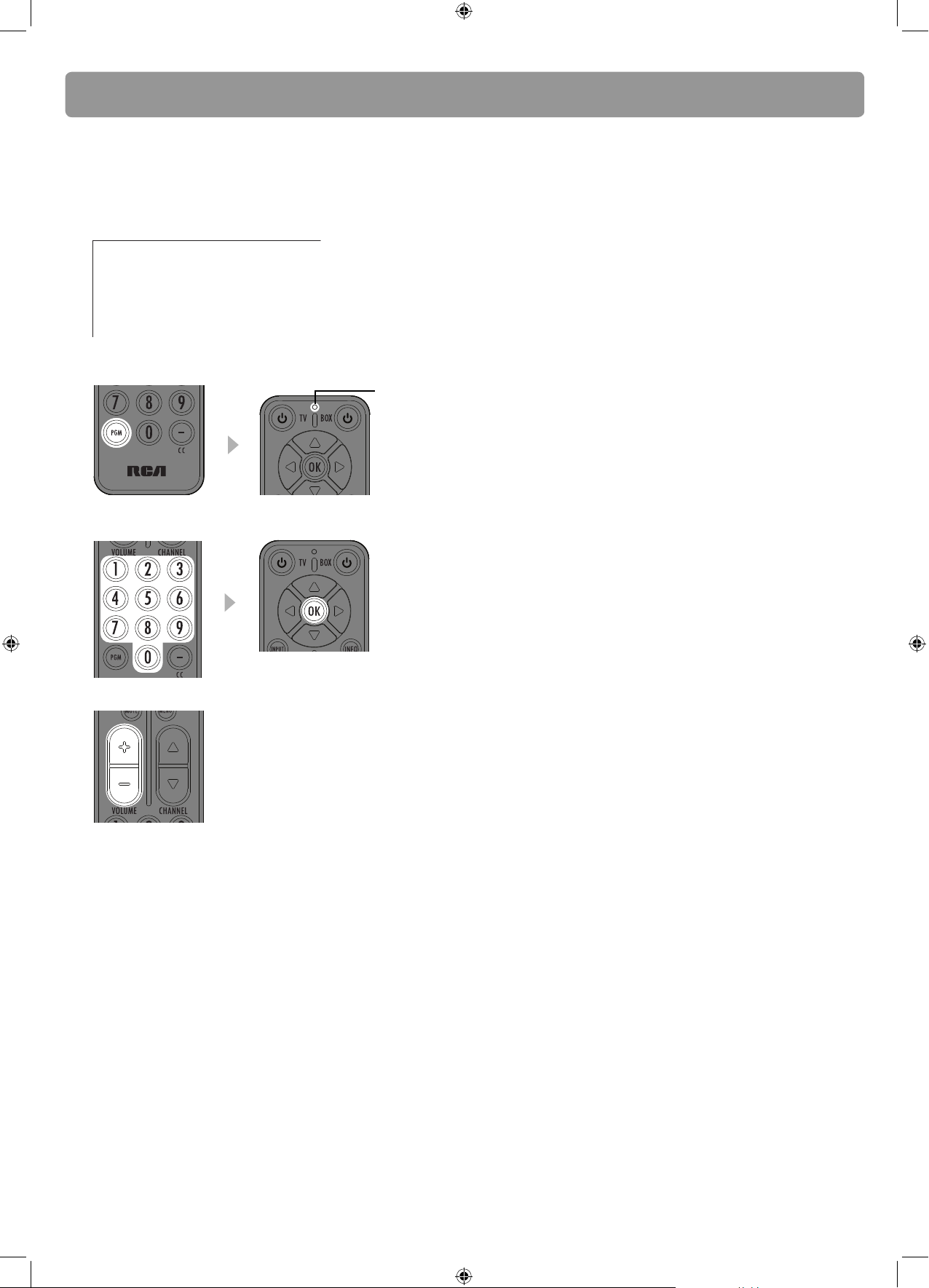
Step 3: Program the supplied remote control
You can control TV sets of all major brands after programming the Converter Box remote control with the PGM key. RCA TV sets
can be controlled directly without programming. Refer to the steps below and the separate Program Code leafl et to guide you
through the programming.
1. Refer to the separate Program Code leafl et. Look for the brand of your TV set and a 3-digit program code next to it. There
may be more than one program code available. Choose any one of them.
Program codes/Códigos de programa
Admiral 002, 128, 183, 189
Advent 191, 258, 260, 275
Adventura 129
Aiko 014, 182
Aiwa 289, 290
• If your TV set is not on the list, skip the rest of this section and go to “Step 4: Initial setup of the converter box”.
2. Press PGM on the remote control. The signal indicator on it remains lit.
signal indicator
3. Enter the 3-digit program code with the number keys. Press OK for confi rmation. The signal indicator will be off when the
program is done.
4. Press the volume keys on this remote control to check if they can adjust the volume of your TV set.
• If you fail to control your TV set, repeat steps 2 to 4 to program again. Try another program code if there is more than one
for your TV brand.
• If the signal indicator remains lit after blinking four times, you may have entered the wrong code. Repeat steps 3 to 4 to
program again. Make sure you have correctly entered the code.
• Refer to User Manual for controlling some features of your TV set with this remote control.
DTA800B_EN(QSG).indd 3DTA800B_EN(QSG).indd 3 12/6/07 10:59:26 AM12/6/07 10:59:26 AM
Page 4
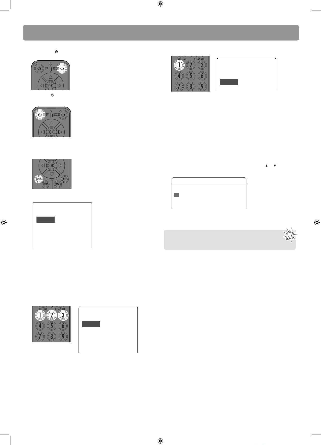
Step 4: Initial setup of the Converter Box
1. Press BOX on the remote control to turn on the
Converter Box.
2. Press TV
(or use the TV remote control) to turn on the
TV set.
3. Press INPUT up to four times (or use the TV remote
control) to select the channel on your TV set to view
images from the converter box.
• The following screen can be seen on your TV when the
correct channel is chosen.
Language
Choose the language to be used in the menu system.
English - 1
Menu text is displayed in English.
5. Press 1 to start automatic channel search.
Channel Scan
Channel scan will search for channels available in your
area. You may have to re-adjust the antenna and
retry the scan to capture all available channels.
Begin - 1
Start channel search.
• To improve TV signal reception, an optional Smart
Antenna which is compatible for connection with the
Converter Box is recommended.
• If a Smart Antenna is connected, press 1 for Quick Scan or
2 for Full Scan. A full scan with Smart Antenna may take
around 40-50 minutes.
• When the scan fi nishes, the Channel List menu displays the
found channels.
• Reposition the antenna and perform the automatic
channel scan again if you cannot fi nd all available
channels.
6. The Channel List shows after scanning, press
or to
highlight a channel and press OK to start viewing.
Channel List
Channel What's on Now What's on Next
2-1 KTVU Stored Current program Next program
2-2 KTVU Stored Current program Next program
4-1 KRON Stored Current program Next program
Your Converter Box is now ready for use!
Español - 2
Français - 3
El texto del menú se exhibe en
español.
Le texte des menus est affiché en
français.
• If you cannot see the above screen on your TV set, check
that:
1) if the converter box has been turned on,
2) if you have programmed the remote control so that the
TV input channel can be selected correctly,
3) if you have correctly connected the TV set with the
Converter Box.
4. Press 1 (for English), 2 (for Spanish) or 3 (for French) to
select the menu language.
Language
Choose the language to be used in the menu system.
English - 1
Español - 2
Français - 3
Menu text is displayed in English.
El texto del menú se exhibe en
español.
Le texte des menus est affiché en
français.
Please read the User Manual for further details on
using the Converter Box.
DTA800B_EN(QSG).indd 4DTA800B_EN(QSG).indd 4 12/6/07 10:59:27 AM12/6/07 10:59:27 AM
 Loading...