


DSL Decoder
User’s Guide
Changing Entertainment. Again.
DSL1500/DSL1510
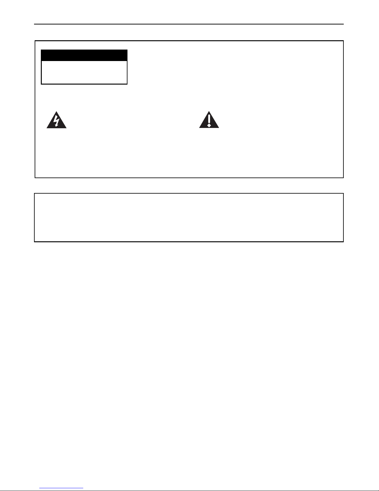
This symbol indicates "dangerous
voltage" inside the product that
presents a risk of electric shock or
personal injury.
WARNING
To reduce the risk of fire or electric shock, do not expose this product to rain or
moisture.
Caution: To reduce the risk of electric shock, do not remove
cover (or back). No user serviceable parts inside. Refer
servicing to qualified service personnel.
This symbol indicates important
instructions accompanying the
product.
Refer to the identification/rating label located on the back panel of your product for its
proper operating voltage.
FCC Regulations state that unauthorized changes or modifications to this equipment may void
the user’s authority to operate it.
CAUTION
RISK OF ELECTRIC SHOCK.
DO NOT OPEN.
Important Information

Table of Contents
1
Chapter 1: Connections and Setup
Things to Consider Before Connecting Components ................. 3
Cables to Connect Components to Your DSL Decoder .............. 3
Choose Your Connection............................................................... 4
TV + DSL Decoder + External Modem ........................................ 5
TV + DSL Decoder ......................................................................... 6
TV + VCR + DSL Decoder ............................................................. 7
A/V Receiver + DSL Decoder ........................................................ 8
Connecting a Secondary DSL Decoder or Other Device with
Home PNA or Ethernet .......................................................... 9
Turn on the TV and DSL Decoder .............................................. 10
Put Batteries in the Remote Control......................................... 10
Put Batteries in the Optional Wireless Keyboard .................... 10
Chapter 2: Remote Control
The Buttons on the Remote Control ..........................................11
Using the INPUT Button ........................................................................................ 12
Programming the Remote to Operate Other Components...... 13
Find Out If You Need to Program the Remote ................................................ 13
Programming the Remote ..................................................................................... 13
How to Use the Remote After You’ve Programmed It............. 14
Code List ...................................................................................... 15
Using the Remote Control to Choose On-screen Menu
Items ...................................................................................... 17
Chapter 3: Decoder Features
Using the On-Screen Keyboard ................................................. 17
Shift, Alt, Ctrl Keys .................................................................................................. 17
Shortcut Keys ............................................................................................................ 17
Using the Web Browser .............................................................. 18
Browser Banner ........................................................................................................ 18
Browser Toolbar ....................................................................................................... 18
Entering a Website Address .................................................................................. 18
Web Page Navigation ............................................................................................. 19
More Features ............................................................................. 19

Table of Contents
2
Viewing Your Bookmarks ....................................................................................... 19
Selecting and Deleting Bookmarks ..................................................................... 19
Searching the Web .................................................................................................. 20
Exiting back to the Browser ................................................................................. 20
Saving Your Bookmarks ......................................................................................... 20
Viewing Your History .............................................................................................. 20
Chapter 4: Additional Information
Troubleshooting ........................................................................... 21
Care and Cleaning ....................................................................... 22
Service Information .................................................................... 22
FCC Declaration of Conformity and Industry Canada
Information ........................................................................... 23
Additional FCC Information ....................................................... 24
Front of the Decoder .................................................................. 25
Back of the Decoder ................................................................... 26
How to Find Your TV’s Video Input Channel ............................ 27
Video Input Channel Variations........................................................................... 27
Accessories ................................................................................... 28
Chapter 1 3
Chapter 1: Connections and Setup
Things to Consider Before Connecting Components
Protect Components From Power Surges
• Connect all components before plugging any power cords into the wall outlet.
• Always turn off the TV and other components before you connect or disconnect any cables.
Position Cables to Avoid Audio Hum or Interference
• Insert all cable plugs firmly into their jacks.
• Place any Audio/Video (A/V) cables to the side(s) of the TV’s back panel instead of straight down the
back after connecting components.
• Try not to coil any twin-lead cables and keep them away from all A/V cables as much as possible.
• Make sure all antennas and cables are properly grounded. Refer to the Safety Tips sheet packed with
your unit for detailed information.
Protect Components From Overheating
• Never block ventilation slots in any component. Arrange the components so that air can circulate
freely.
• Do not stack components.
• Allow adequate ventilation when placing components in a stand.
• Place an amplifier or other hot component on the top shelf of a stand so heated air rising from it
will not flow around other components.
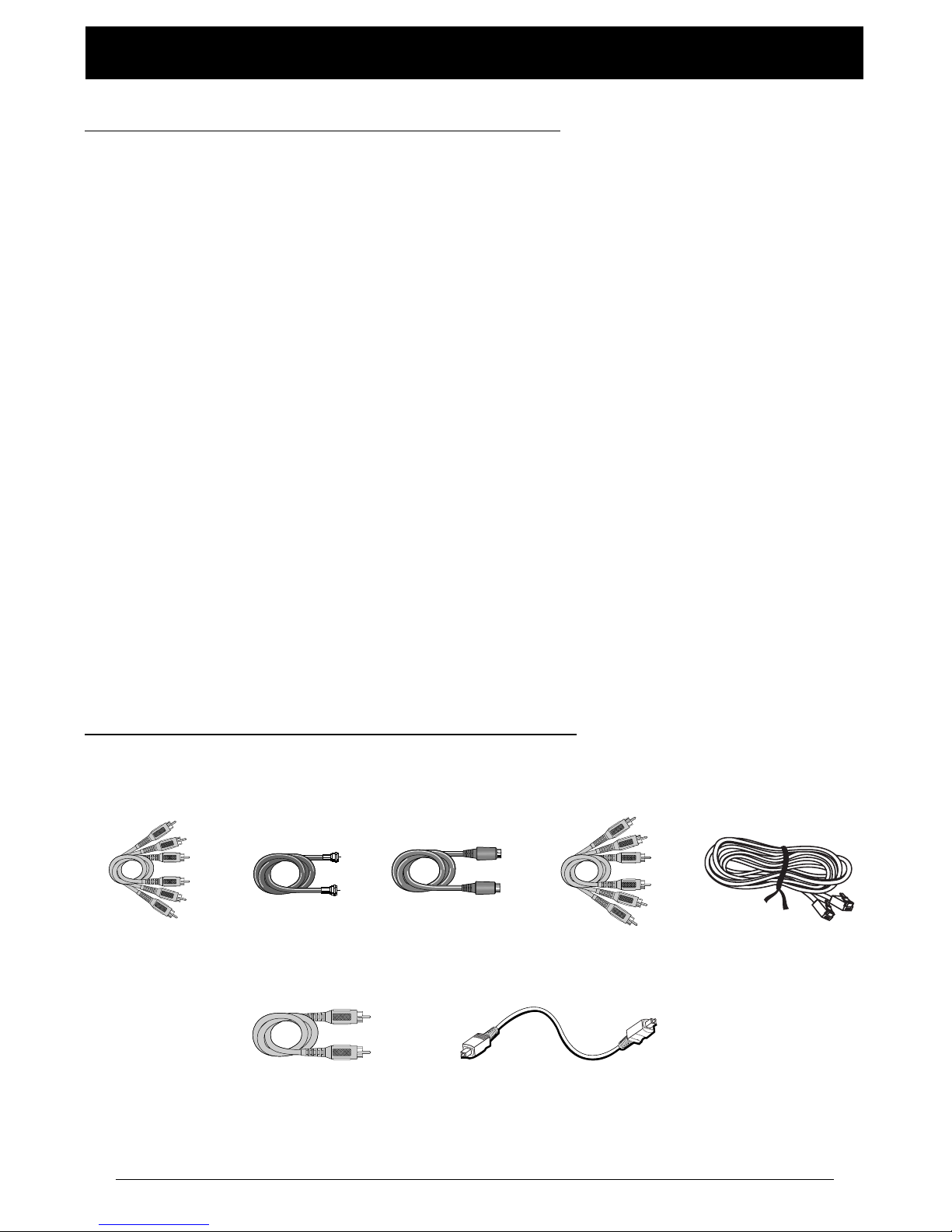
Home PNA and
Ethernet cables
(included)
Cables to Connect Components to Your DSL Decoder
The pictures below show the cables that can be used for the connections represented in this book.
Audio/Video cables
(included)
Coaxial cable Component Video
(Y•Pb•Pr) cables
S-Video cable
Digital Coaxial cable
Digital Optical cable
Chapter 1: Connections and Setup
4 Chapter 1
Illustrations contained in this document are for representation only.
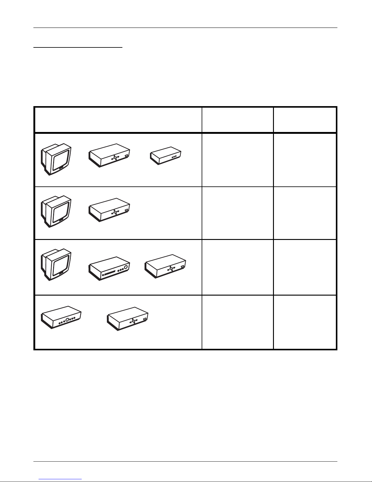
Components
Connection Title Go To
T
V
DSL Decoder
VCR
T
V
D
S
L
D
e
c
o
d
e
r
A
/V
R
e
c
e
iv
e
r
D
S
L
D
e
c
o
d
e
r
T
V
D
S
L
D
e
c
o
d
e
r
E
x
t
e
r
n
a
l
M
o
d
e
m
TV + DSL Decoder page 5
+ External Modem
TV + DSL Decoder page 6
TV + VCR + page 7
DSL Decoder
A/V Receiver + page 8
DSL Decoder
Choose Your Connection
There are several ways to hook up your DSL decoder, depending on the components connected. Please
use the following chart to determine which connection is best for you and proceed to the appropriate
page.
Note: For assistance in connecting your decoder, contact your service provider.

Chapter 1: Connections and Setup
Chapter 1 5
Illustrations contained in this document are for representation only.
TV
The back of your
TV might not look
exactly like the
one shown here.
D
S
L
D
e
c
o
d
e
r
From Cable
or TV Antenna
CABLE/
ANTENNA
TV
VIDEO
R
L / MONO
S-VIDEO
AUDIO
L
IN
OUT
DSL
DECODER
From DSL or other Broadband Connection
EXTERNAL
MODEM
IN FROM
ANTENNA
AC INLET~
OUT TO TV
RF COAXIAL
COMPONENT VIDEO OUT
Y
Pb
Pr
AUDIO
OUT
DIGITAL
AUDIO OUT
OPTICAL
COAXIAL
R
L
R
L
RECORDER
CONTROL
SMART CARD
VIDEO
OUT
S-VIDEO
OUT
NETWORK
ETHERNET
PHONE
LINE IN
HPNA
ETHERNET
DSL LINE
IN
2
4
3
E
x
t
e
r
n
a
l
M
o
d
e
m
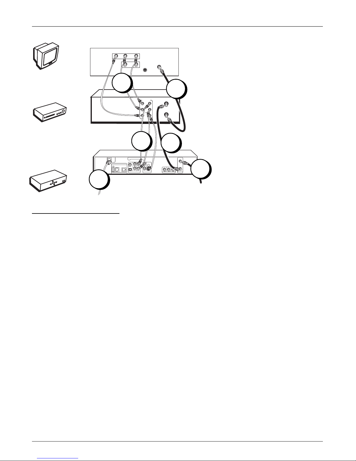
TV + DSL Decoder + External Modem
1. Connect the Decoder to the TV
A. Connect one end of the RF coaxial cable to the OUT TO TV jack on the back of the decoder and
the other end to the TV’s antenna in jack (sometimes labeled CABLE/ANTENNA).
B. Connect audio/video cables to the AUDIO OUT R and L jacks on the back of the decoder (color
coded, red and white), and to the VIDEO OUT jack (yellow). Connect the other ends of the cables
to the corresponding input jacks on the TV (sometimes labeled VIDEO, AUDIO L/MONO, and
AUDIO R).
Note: If your TV has an S-Video input or component video input, we recommend you make the video connection by using
these jacks instead. Remember to connect audio cables for these connections as S-Video and component video only
carry the picture signal, not the sound.
2. Connect the antenna/cable feed to the Decoder
Connect the cable or antenna RF coaxial cable to the IN FROM ANTENNA jack on your decoder.
Note: To turn off the decoder signal to allow other signals to pass through, press the ANTENNA button on the remote
(may or may not be supported) or press the OFF button on the remote to put the decoder into stand-by mode.
3. Connect the DSL line to the DSL Modem
Connect the DSL line from the wall jack to the DSL LINE IN jack on your modem.
4. Connect the ethernet cable to the DSL Decoder
Connect one end of the ethernet cable to the ETHERNET jack on the modem and the other end to
the ETHERNET jack on the decoder.
5. Plug the power cord into the AC outlet.
Go To Page 10
1B
1A
Chapter 1: Connections and Setup
6 Chapter 1
Illustrations contained in this document are for representation only.
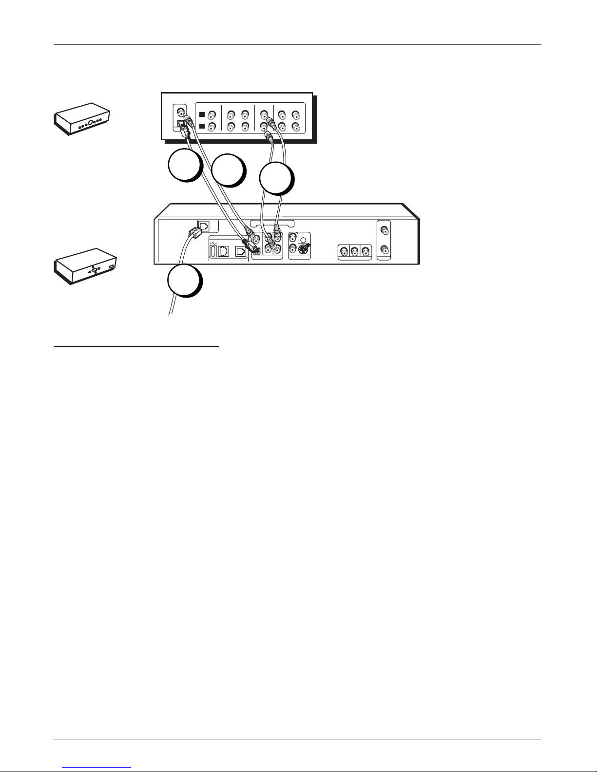
TV + DSL Decoder
1. Connect the Decoder to the TV
A. Connect one end of the RF coaxial cable to the OUT TO TV jack on the back of the decoder and
the other end to the TV’s antenna in jack (sometimes labeled CABLE/ANTENNA).
B. Connect audio/video cables to the AUDIO OUT R and L jacks on the back of the decoder (color
coded, red and white), and to the VIDEO OUT jack (yellow). Connect the other ends of the cables
to the corresponding input jacks on the TV (sometimes labeled VIDEO, AUDIO L/MONO, and
AUDIO R).
Note: If your TV has an S-Video input or component video input, we recommend you make the video connection by using
these jacks instead. Remember to connect audio cables for these connections as S-Video and component video only
carry the picture signal, not the sound.
2. Connect the antenna/cable feed to the Decoder
Connect the cable or antenna RF coaxial cable to the IN FROM ANTENNA jack on your decoder.
Note: To turn off the decoder signal to allow other signals to pass through, press the ANTENNA button on the remote
(may or may not be supported) or press the OFF button on the remote to put the decoder into stand-by mode.
3. Connect the DSL line to the Decoder
Connect the DSL line from the wall jack to the DSL LINE IN jack on your decoder.
4. Plug the power cord into the AC outlet.
Go To Page 10
From Cable
or TV Antenna
CABLE/
ANTENNA
TV
VIDEO
R
L / MONO
S-VIDEO
AUDIO
L
IN
OUT
DSL
DECODER
IN FROM
ANTENNA
AC INLET~
OUT TO TV
RF COAXIAL
COMPONENT VIDEO OUT
Y
Pb
Pr
AUDIO
OUT
DIGITAL
AUDIO OUT
OPTICAL
COAXIAL
R
L
R
L
RECORDER
CONTROL
SMART CARD
VIDEO
OUT
S-VIDEO
OUT
NETWORK
ETHERNET
PHONE
LINE IN
HPNA
From DSL or other Broadband Connection
DSLLIN
E IN
TV
The back of your
TV might not look
exactly like the
one shown here.
D
S
L
D
e
c
o
d
e
r
2
3
1B
1A
Chapter 1: Connections and Setup
Chapter 1 7
Illustrations contained in this document are for representation only.
TV + VCR + DSL Decoder
1. Connect the VCR to the TV
A. Connect one end of the RF coaxial cable to the RF OUT jack on the back of the VCR and the
other end to the TV’s antenna in jack (sometimes labeled CABLE/ANTENNA).
B. Connect audio/video cables to the AUDIO OUT R and L jacks on the back of the VCR (color
coded, red and white), and to the VIDEO OUT jack (yellow). Connect the other ends of the cables
to the corresponding input jacks on the TV (sometimes labeled VIDEO, AUDIO L/MONO, and
AUDIO R).
2. Connect the DSL Decoder to the VCR
A. Connect an RF coaxial cable to the OUT TO TV jack on the decoder and to the ANT. IN jack on
the VCR (sometimes labeled IN FROM ANTENNA).
B. Connect audio/video cables to the AUDIO IN R and L jacks on the back of the VCR (color coded,
red and white), and to the VIDEO IN jack (yellow). Connect the other ends of the cables to the
AUDIO OUT R and L and the VIDEO OUT jacks on the decoder.
3. Connect the antenna to your DSL Decoder
If necessary, connect an antenna or cable box RF coaxial cable (not included) to the IN FROM
ANTENNA jack on the decoder.
Note: To turn off the decoder signal to allow other signals to pass through, press the ANTENNA button on the remote
(may or may not be supported) or press the OFF button on the remote to put the decoder into stand-by mode.
4. Connect the DSL line to the Decoder
Connect the DSL line from the wall jack to the DSL LINE IN jack on your decoder.
5. Plug the power cord into the AC outlet.
Go To Page 10
The back of your
TV might not look
exactly like the
one shown here.
The back of your
VCR might not
look exactly like
the one shown
here.
V
C
R
T
V
D
S
L
D
e
c
o
d
e
r
From Cable
or TV Antenna
CABLE/
ANTENNA
VCR
TV
VIDEO
R
L / MONO
S-VIDEO
AUDIO
L
IN
OUT
ANT. IN
RF OUT
VIDEO
AUDIO
OUT
IN
R
L
DSL
DECODER
IN FROM
ANTENNA
AC INLET~
OUT TO TV
RF COAXIAL
COMPONENT VIDEO OUT
Y
Pb
Pr
AUDIO
OUT
DIGITAL
AUDIO OUT
OPTICAL
COAXIAL
R
L
R
L
RECORDER
CONTROL
SMART CARD
VIDEO
OUT
S-VIDEO
OUT
NETWORK
ETHERNET
PHONE
LINE IN
HPNA
DSLLIN
E IN
From DSL or other Broadband Connection
4
3
1B
1A
2B
2C
Chapter 1: Connections and Setup
8 Chapter 1
Illustrations contained in this document are for representation only.
A/V Receiver + DSL Decoder
1. Connect the A/V Receiver to your Decoder
A. Connect audio/video cables to the AUDIO OUT R and L jacks on the back of the decoder (color
coded, red and white). Connect the other ends of the cables to the corresponding input jacks on your
A/V receiver (sometimes labeled VIDEO, AUDIO L/MONO, and AUDIO R). You may also want to
connect video to your receiver (or TV using instructions on the previous pages).
– OR –
B. If you have a Dolby Digital or audio/video receiver with a digital optical jack, remove the
protective cap from the OPTICAL DIGITAL AUDIO OUT jack on the back of the decoder (if necessary)
and also remove the protective caps from your digital optical cable.
Connect one end of the digital optical cable to the OPTICAL AUDIO OUT jack on the back of the
decoder and the other end to the corresponding input jack on your A/V receiver (sometimes labeled
OPTICAL IN). You may also want to connect video to your receiver (or TV using instructions on the
previous pages).
– OR –
C. If you have a Doby Digital or audio/video receiver with a digital coaxial jack, connect one end of
the digital coaxial cable to the COAXIAL DIGITAL AUDIO OUT jack on the back of the decoder and the
other end to the corresponding input jack on your A/V receiver (sometimes labeled COAXIAL IN). You
may also want to connect video to your receiver (or TV using instructions on the previous pages).
2. Connect the DSL line to the Decoder
Connect the DSL line from the wall jack to the DSL LINE IN jack on your decoder.
3. Plug the power cord into the AC outlet.
Go To Page 10
The back of your
receiver might not
look exactly like
the one shown
here.
A
/
V
R
e
c
e
i
v
e
r
D
S
L
D
e
c
o
d
e
r
IN FROM
ANTENNA
AC INLET~
OUT TO TV
RF COAXIAL
COMPONENT VIDEO OUT
Y
Pb
Pr
AUDIO
OUT
DIGITAL
AUDIO OUT
OPTICAL
COAXIAL
R
L
R
L
RECORDER
CONTROL
SMART CARD
VIDEO
OUT
S-VIDEO
OUT
NETWORK
ETHERNET
PHONE
LINE IN
HPNA
IN
OUT
VCR
IN
TV
IN
OUT
TAPE
IN
CD
L
R
DSL
DECODER
A/V RECEIVER
From DSL or other Broadband Connection
OPTICAL
COAX
DSLLIN
E IN
Manufactured under license from Dolby Laboratories. “Dolby” and the double-D symbol are trademarks of
Dolby Laboratories. Confidential unpublished works. © 1992-1997 Dolby Laboratories, Inc. All right reserved.
2
1B
1A
1C
 Loading...