

RF Modulator Kit
with S-Video Input
DH93RF User's Manual
Consulte el reverso para instrucciones en español
This RF Modulator Kit includes everything you need to convert the separate audio and video
signals (from a video camera, computer, portable VCR, or satellite receiver, for example) into an
RF TV signal that you can view through the RF jack on your TV set.
The FCC Wants You to Know
This device complies with Part 15 of FCC Rules. Operation is subject to the
following two conditions:
(1) This device may not cause harmful interference, and (2) this device
must accept any interference received, including interference that may
cause undesired operation.
Your modulator might cause TV or radio interference even when is operating
properly. To determine whether your modulator is causing the interference,
turn it off. If the interference goes away, your modulator is causing it.
Try to eliminate the interference by:
• moving your RF Modulator away from the receiver
• connecting your RF Modulator to an outlet that is on a different
electrical circuit from the receiver
• contacting your local store for help
If you cannot eliminate the interference, the FCC requires that you stop
using your RF Modulator.
Changes or modifications not expressly approved by the party responsible for
compliance could void the user's FCC authorization to operate this equipment.
Note to the CATV System Installer: This reminder is provided to call
the CATV system installer’s attention to article 820-22 of the NEC that
provides guidelines for proper grounding and, in particular, specifies that
the cable ground shall be connected to the grounding system of the
building, as close to the point of cable entry as practical.
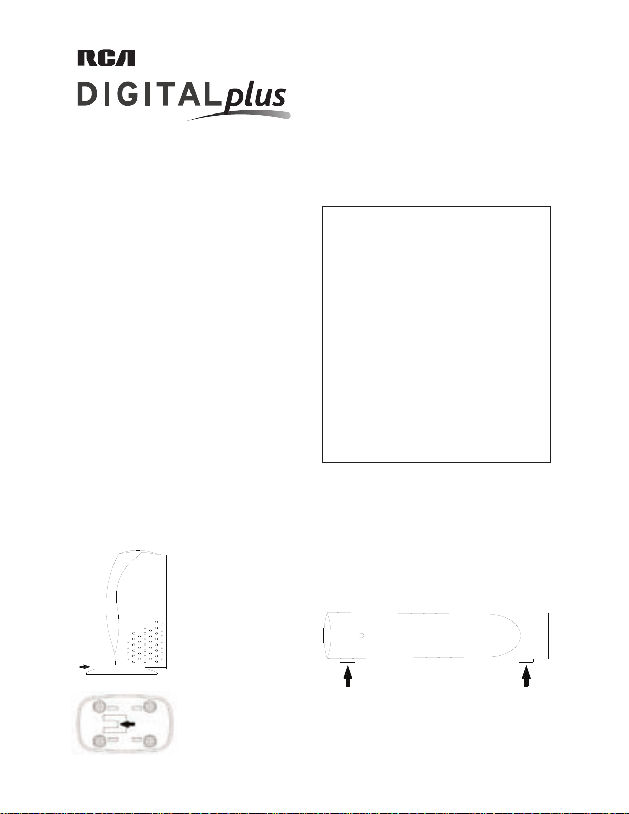
Installation
You can seat the RF modulator either vertically or horizontally.
To seat the RF Modulator vertically :
Slide the seat plate (included)
onto the bottom of the RF
Modulator until the locking
tab of the seat plate clicks in
to secure the plate to the RF
Modulator.
ON
To seat the RF Modulator horizontally :
Attach the four self-adhesive rubber pads (included) to
the side face of the RF Modulator.
Then, turn the RF Modulator onto the side with the
rubber pads.
Note: To remove the seat plate
once you’ve seated the RF
Modulator, pull up the locking
tab on the bottom of the plate
and push the seat plate off of
the RF Modulator.
What’s included
In addition to the RF Modulator, this kit has the following
cables for connecting your component and your TV:
• 1 3FT. Audio/Video Cable
• 1 3FT. Coaxial Cable
These are all the cables you need for a basic connection.
Depending on the connections offered by your TV and your
input component, you might also want to use the following
accessories:
• 1 S-Video Cable (not included)
• 1 75-ohm to 300-ohm matching transformer (not
included)
Connections
Follow these steps to connect your RF Modulator.
1. Connecting to your video source
How you connect the RF Modulator to your video source (DVD player, video game system, etc.) depends on the outputs
your video source has. Look at the back panel of your video source to see which of the following best matches the
connections it offers. Then, follow the directions for that connection.
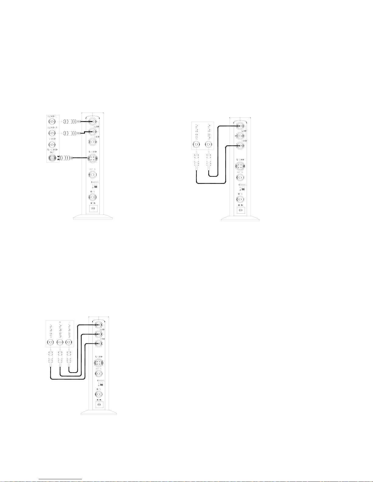
S-Video and Stereo Audio Connection
Video Source
A/V Cable
RF Modulator
1. Plug the red and white
connectors on one end
of the provided stereo A/V cable into the
audio input jacks on
the RF Modulator.
Do not plug in the yel
-
low connector.
2. Plug the red and white
connectors on the
cable’s other end into
the audio output jacks
on the video source,
using the color coding
on the connectors as a
guide.
Do not plug in the yel
-
low connector.
Video Source
A/V Cable
RF Modulator
1. Plug the connectors on
one end of the provided stereo A/V cable
into the video and
audio input jacks on
the RF Modulator.
2. Plug the connectors
on the cable’s other
end into to video and
audio output jacks on
the video source, using
the color coding on the
connectors as a guide.
Video
RF Modulator
Source
3. Plug the connector on one end of an S-Video cable
(not included) into the S-Video input jack on the RF
Modulator.
4. Plug the connector on the cable’s other end into the
S-Video output jack on the video source.
Video and Stereo Audio Connection
Video and Mono Audio
Connection
1. Plug the connectors on
one end of the provided
A/V cable into the video
and audio input jacks on
the RF Modulator (using
either the AUDIO R or L
jack).
2. Plug the cable’s other
ends into the video and
audio jacks on the video
source.
Note: The audio signal will be modulated to mono,
whether the video source is stereo or mono.
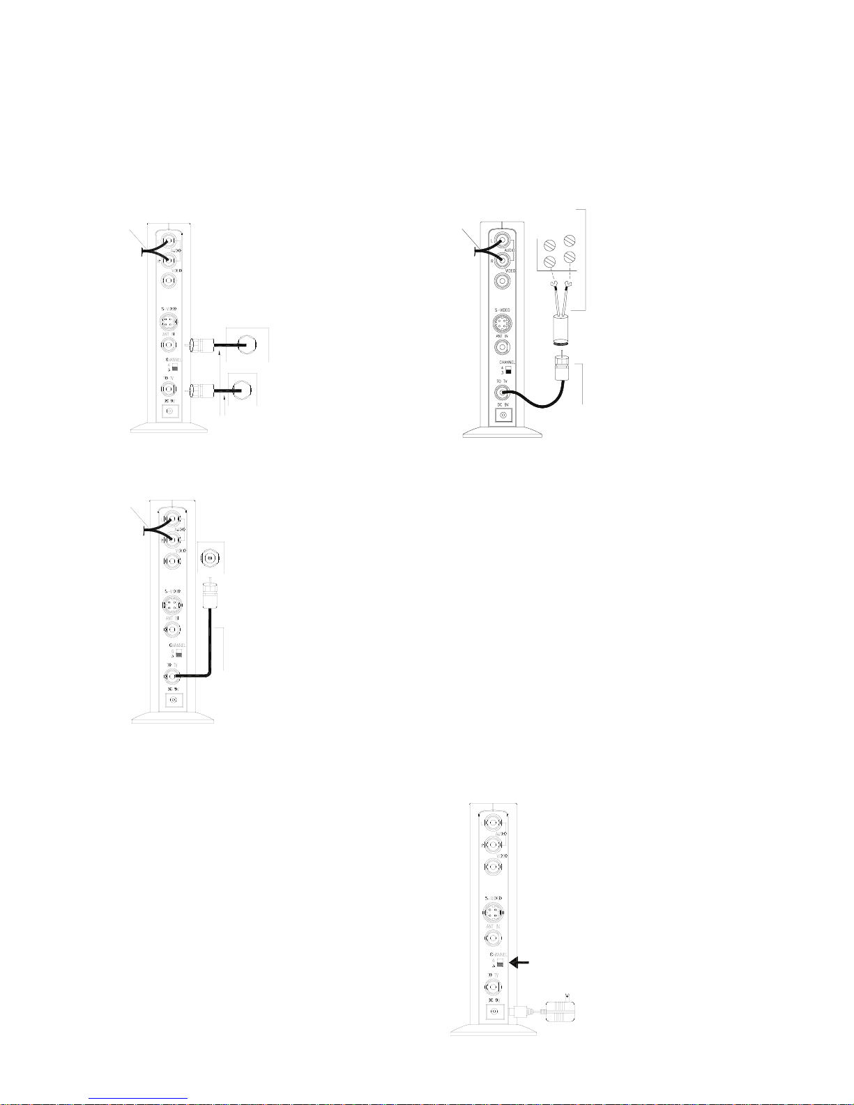
2. Connecting to your TV
How you connect your RF Modulator to your TV depends on what RF input your TV offers. Look at the back panel
of your TV to see which of the following best matches the connections it offers. Then, follow the directions for that
connection.
A/V Cable
ANTENNA /CABLE
TV
VHF/UHF
VHF/UHF
75-Ohm Coaxial Cables
1. Disconnect the
cable connected to
the TV’s RF input.
2. Reconnect this cable
to the RF Modulator’s
ANT IN jack.
3. Connect the pro
vided coaxial cable
between the TO TV
VHF/UHF jack on the
RF Modulator and
the RF input on your
TV.
Something else connected to the TV’s RF jack
(like an antenna, VCR, or cable signal)
75-Ohm
RF Modulator
A
/V Cable
Coaxial Cables
VHF/UHF
TV
Connect the provided
coaxial cable between
to the TO TV jack on the
RF modulator and the
RF jack on your TV.
75-Ohm
RF Modulator
A/V Cable
Coaxial Cables
TV
VHF
UHF
75-Ohm to 300-Ohm
Matching Transformer
Your TV has only 300-ohm VHF screw terminals
Use a 75-ohm-to-300ohm matching transformer
to make the connection.
Nothing connected to the TV’s RF jack
3. Plugging in the RF Modulator
Plug the RF Modulator’s power cord into a standard AC
outlet.
Note: This power unit is intended to be correctly oriented
in a vertical or floor mount position.
4. Setting the CHANNEL 3/4 switch
RF Modulator
CHANNEL 3/4
1. Turn on your TV and
set it to either Channel
3 or 4, whichever is
not used for regular
broadcasts in your
area.
2. Set the RF Modulator’s
CHANNEL 3/4 switch
to the same channel
you set the TV (3 or
4).
 Loading...