

Page 1
RF Modulator
ON
with S-Video Input
DH91RF User's Manual
Consulte el reverso para instrucciones en español
This RF Modulator converts the separate audio and video signals (from a video camera,
computer, portable VCR, or satellite receiver, for example) into an RF TV signal that you can
view through the RF jack on your TV set.
The FCC Wants You to Know
This device complies with Part 15 of FCC Rules. Operation is subject to the
following two conditions:
(1) This device may not cause harmful interference, and (2) this device
must accept any interference received, including interference that may
cause undesired operation.
Your modulator might cause TV or radio interference even when is
operating properly. To determine whether your modulator is causing the
interference, turn it off. If the interference goes away, your modulator
is causing it.
Try to eliminate the interference by:
• moving your RF Modulator away from the receiver
• connecting your RF Modulator to an outlet that is on a different
electrical circuit from the receiver
• contacting your local store for help
If you cannot eliminate the interference, the FCC requires that you stop
using your RF Modulator.
Changes or modifications not expressly approved by the party responsible
for compliance could void the user's FCC authorization to operate this
equipment.
Required Parts
The following items (not supplied) are required to connect your RF
Modulator to a video input source and your TV.:
• one audio/video cable
• two 75-ohm coaxial cables with F-type connectors
You may also need a 75-ohm-to-300-ohm matching transformer (if your
TV does not have a VHF 75-ohm F-connector).
Note: The audio signal will be modulated to mono, whether the video
source is stereo or mono.
Note to the CATV System Installer: This reminder is provided to call the
CATV system installer’s attention to article 820-22 of the NEC that provides
guidelines for proper grounding and, in particular, specifies that the cable
ground shall be connected to the grounding system of the building, as
close to the point of cable entry as practical.
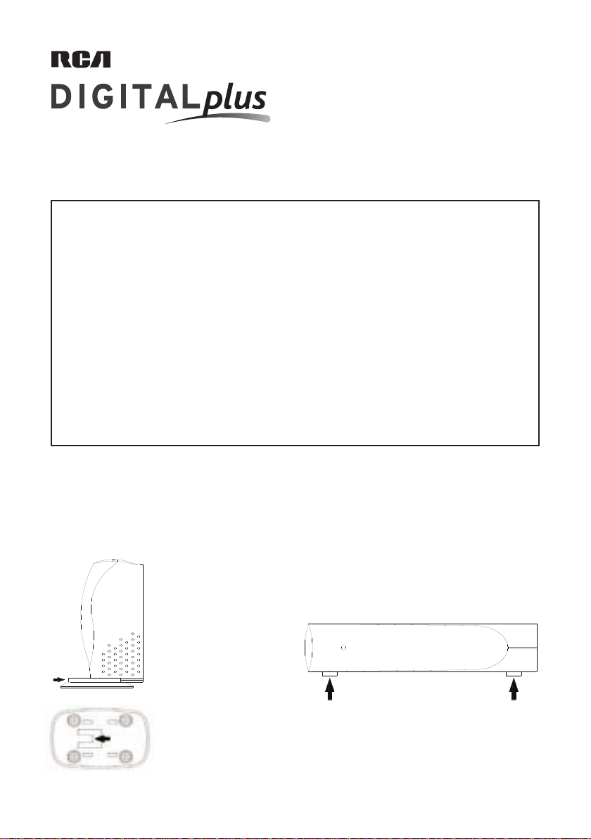
Installation
You can seat the RF modulator either vertically or horizontally.
To seat the RF Modulator vertically :
Slide the seat plate (included)
onto the bottom of the RF
Modulator until the locking
tab of the seat plate clicks in
to secure the plate to the RF
Modulator.
To seat the RF Modulator horizontally :
Attach the four self-adhesive rubber pads (included) to
the side face of the RF Modulator.
Then, turn the RF Modulator onto the side with the
rubber pads.
Note: To remove the seat plate
once you’ve seated the RF
Modulator, pull up the locking
tab on the bottom of the plate
and push the seat plate off of
the RF Modulator.
Page 2
Video Source
A/V Cable
RF Modulator
Video Source
A/V Cable
RF Modulator
Video
RF Modulator
Source
Connections
Follow these steps to connect your RF Modulator.
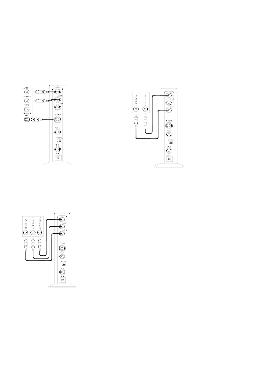
1. Connecting to your video source
How you connect the RF Modulator to your video source (DVD player, video game system, etc.) depends on the outputs
your video source has. Look at the back panel of your video source to see which of the following best matches the
connections it offers. Then, follow the directions for that connection.
S-Video and Stereo Audio Connection
1. Plug the connectors on
one end of a stereo
audio cable into the
audio input jacks on
the RF Modulator.
2. Plug the connectors
on the cable’s other
end into the audio output jacks on the video
source, using the color
coding on the connectors as a guide.
3. Plug the connector on
one end of an S-Video
cable into the S-Video
input jack on the RF
Modulator.
4. Plug the connector on the cable’s other end into the
S-Video output jack on the video source.
Video and Stereo Audio Connection
1. Plug the connectors on
one end of a stereo A/V
cable into the video
and audio input jacks
on the RF Modulator.
2. Plug the connectors
on the cable’s other
end into to video and
audio output jacks on
the video source, using
the color coding on the
connectors as a guide.
Video and Mono Audio Connection
1. Plug the connectors on
one end of an A/V cable
into the video and audio
input jacks on the RF
Modulator (using either
the AUDIO R or L jack).
2. Plug the cable’s other
ends into the video and
audio jacks on the video
source.
Page 3
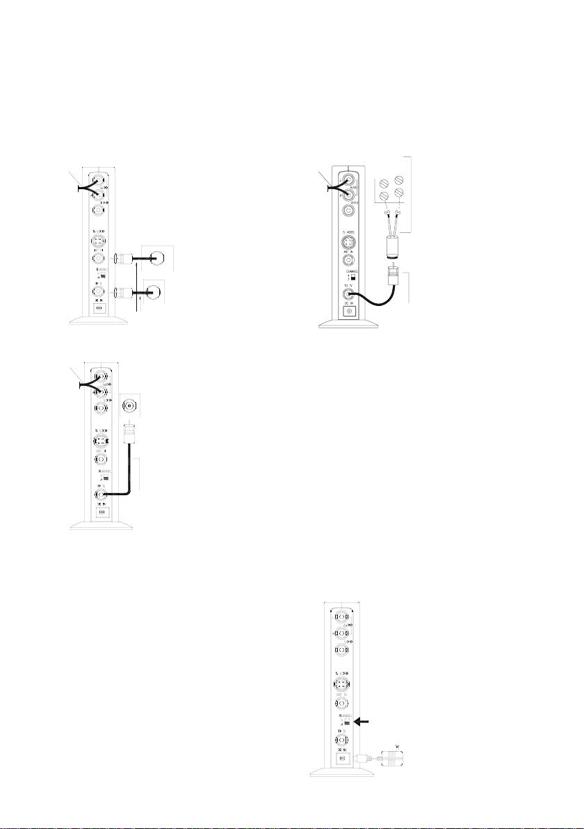
2. Connecting to your TV
A/V Cable
ANTENNA /CABLE
TV
VHF/UHF
VHF/UHF
75-Ohm Coaxial Cables
75-Ohm
RF Modulator
A
/V Cable
Coaxial Cables
VHF/UHF
TV
75-Ohm
RF Modulator
A/V Cable
Coaxial Cables
TV
VHF
UHF
75-Ohm to 300-Ohm
Matching Transformer
RF Modulator
CHANNEL 3/4
How you connect your RF Modulator to your TV depends on what RF input your TV offers. Look at the back panel
of your TV to see which of the following best matches the connections it offers. Then, follow the directions for that
connection.
Something else connected to the TV’s RF jack
(like an antenna, VCR, or cable signal)
1. Disconnect the
cable connected to
the TV’s RF input.
2. Reconnect this cable
to the RF Modulator’s
ANT IN jack.
3. Connect a coaxial
cable between the
TO TV VHF/UHF jack
on the RF Modulator
and the RF input on
your TV.
Nothing connected to the TV’s RF jack
Connect a 75-ohm
coaxial cable between
to the TO TV jack on the
RF modulator and the
RF jack on your TV.
Your TV has only 300-ohm VHF screw terminals
Use a 75-ohm-to-300ohm matching transformer
to make the connection.
3. Plugging in the RF Modulator
Plug the RF Modulator’s power cord into a standard AC
outlet.
Note: This power unit is intended to be correctly oriented
in a vertical or floor mount position.
4. Setting the CHANNEL 3/4 switch
1. Turn on your TV and
set it to either Channel
3 or 4, whichever is
not used for regular
broadcasts in your
area.
2. Set the RF Modulator’s
CHANNEL 3/4 switch
to the same channel
you set the TV (3 or
4).
Page 4

Care
To enjoy your RF Modulator for a long time:
• Keep the modulator dry. If it gets wet, wipe it dry
immediately.
• Use and store the modulator only in normal temperature
environments.
• Handle the modulator gently and carefully. Don’t drop it.
• Keep the modulator away from dust and dirt.
• Wipe the modulator with a damp cloth occasionally to
keep it looking new.
Modifying or tampering with the modulator’s internal
components can cause a malfunction and invalidate its
warranty and void your FCC authorization to operate it. If
your modulator is not performing as it should, take it to
your local store for assistance.
Specifications
Video Carrier Output Level .................................69dBμV
RF Output Channels ..............................................3 or 4
RF Output Impedance ......................................75 Ohms
Audio Input Impedance .............................13±3K Ohms
TV to ANT Insertion Loss 50 - 806 MHz ................. -2dB
DC Adapter .............................................. 9 VDC/100mA
Dimensions .........................523/32 x 3 x 113/64 inches
(145 x 75 x 30 mm)
Weight ................................................... 15 oz (.430 kg)
Specifications are typical; individual units might vary.
Specifications are subject to change and improvement
without notice.
12 Month Limited Warranty
Audiovox Electronics Corporation (the “Company”) warrants to the original retail purchaser of this product that should
this product or any part thereof, under normal use and conditions, be proven defective in material or workmanship
within 12 months from the date of original purchase, such defect(s) will be repaired or replaced (at the Company’s
option) without charge for parts and repair labor. To obtain repair or replacement within the terms of this Warranty,
the product along with any accessories included in the original packaging is to be delivered with proof of warranty
coverage (e.g. dated bill of sale), specification of defect(s), transportation prepaid, to the Company at the address
shown below. Do not return this product to the Retailer.
This Warranty is not transferable and does not cover product purchased, serviced or used outside the United States or
Canada. The Warranty does not extend to the elimination of externally generated static or noise. This Warranty does
not apply to costs incurred for installation, removal or reinstallation of the product, or, if in the Company’s opinion,
the product has been damaged through acts of nature, alteration, improper installation, mishandling, misuse, neglect,
accident, or the simultaneous use of different battery types (e.g. alkaline, standard or rechargeable). This Warranty
does not cover damage caused by an AC adapter not provided with the product.
THE EXTENT OF THE COMPANY’S LIABILITY UNDER THIS WARRANTY IS LIMITED TO THE REPAIR OR REPLACEMENT
PROVIDED ABOVE AND, IN NO EVENT, SHALL THE COMPANY’S LIABILITY EXCEED THE PURCHASE PRICE PAID BY
PURCHASER FOR THE PRODUCT.
This Warranty is in lieu of all other express warranties or liabilities. ANY IMPLIED WARRANTIES, INCLUDING ANY
IMPLIED WARRANTY OF MERCHANTABILITY OR FITNESS FOR A PARTICULAR PURPOSE, SHALL BE LIMITED TO
DURATION OF THIS WARRANTY. ANY ACTION FOR BREACH OF ANY WARRANTY HEREUNDER, INCLUDING ANY IMPLIED
WARRANTY, MUST BE BROUGHT WITHIN A PERIOD OF 24 MONTHS FROM THE DATE OF ORIGINAL PURCHASE. IN NO
CASE SHALL THE COMPANY BE LIABLE FOR ANY CONSEQUENTIAL OR INCIDENTAL DAMAGES WHATSOEVER. No person
or representative is authorized to assume for the Company any liability other than expressed herein in connection with
the sale of this product.
Some states/provinces do not allow limitations on how long an implied warranty lasts or the exclusion or limitation of
incidental or consequential damage so the above limitations or exclusions may not apply to you. This Warranty gives
you specific legal rights and you may also have other rights which vary from state/province to state/province.
U.S.A.: Audiovox Electronics Corporation, 150 Marcus Blvd., Hauppauge, New York 11788
CANADA: Audiovox Return Center, c/o Genco, 6685 Kennedy Road, Unit 3, Door 16, Mississauga, Ontario L5T 3A5
© 2007 Audiovox Accessories Corporation
111 Congressional Blvd., Suite 350
Carmel, IN 46032
www.rca.com
Trademark(s) ®Registered
Made in China
Printed in China
DH91RF US IB 00
Page 5

DH91RF US IB 00
Marca(s) Registrada(s) ®
Impreso en China
Fabricado en China
www.rca.com
Carmel, IN 46032
111 Congressional Blvd., Suite 350
© 2007 Audiovox Accessories Corporation
CANADÁ: Audiovox Return Center, c/o Genco, 6685 Kennedy Road, Unit 3, Door 16, Mississauga, Ontario L5T 3A5
EE.UU: Audiovox Electronics Corporation, 150 Marcus Blvd., Hauppauge, New York 11788
Esta Garantía le confiere derechos legales específicos; según el estado/provincia, puede disfrutar además de otros derechos.
daños incidentales o emergentes, de modo que es posible que las limitaciones o exclusiones anteriores no se apliquen en su caso.
Algunos estados/provincias no permiten limitaciones sobre la duración de una garantía implícita o la exclusión o la limitación de
la expresada aquí en conexión con la venta de este producto.
INCIDENTALES. Ninguna persona ni representante está autorizado a asumir, a nombre de la Compañía, ninguna responsabilidad salvo
A PARTIR DE LA FECHA DE COMPRA ORIGINAL. EN NINGÚN CASO LA COMPAÑÍA SERÁ RESPONSABLE POR DAÑOS EMERGENTES O
EN EL PRESENTE, INCLUYENDO CUALQUIER GARANTÍA IMPLÍCITA, DEBERÁ PRESENTARSE DENTRO DE UN PERÍODO DE 24 MESES
ESTARÁN LIMITADAS A LA DURACIÓN DE ESTA GARANTÍA. CUALQUIER ACCIÓN PARA EL INCUMPLIMIENTO DE CUALQUIER GARANTÍA
INCLUYENDO CUALQUIER GARANTÍA IMPLÍCITA DE COMERCIABILIDAD O ADAPTABILIDAD PARA UN PROPÓSITO EN PARTICULAR
Esta Garantía reemplaza cualesquiera otras responsabilidades o garantías expresas. CUALESQUIERA GARANTÍAS IMPLÍCITAS,
POR EL COMPRADOR DE ESTE PRODUCTO.
PROVISTO ARRIBA Y, EN NINGÚN CASO, DEBERÁ LA RESPONSABILIDAD DE LA COMPAÑÍA EXCEDER EL PRECIO DE COMPRA PAGADO
EL ALCANCE DE LA RESPONSABILIDAD DE LA COMPAÑÍA BAJO ESTA GARANTÍA ESTÁ LIMITADO A LA REPARACIÓN O EL REEMPLAZO
adaptador de CA que no haya sido suministrado con el producto.
de diferentes tipos de baterías (por ejemplo, alcalinas, típicas o recargables). Esta Garantía no incluye daños ocasionados por un
a causas de fuerza mayor, alteraciones, instalación inadecuada, abuso, uso indebido, negligencia, accidente, o el uso simultáneo
instalación, remoción o reinstalación de este producto, o, si es opinión de la Compañía, que este producto ha sufrido daños debido
Garantía no incluye la eliminación de estática o ruido generados externamente. Esta Garantía no incluye los costos incurridos en la
Esta Garantía no es transferible y no cubre un producto adquirido, mantenido o utilizado fuera de los Estados Unidos o Canadá. Esta
la dirección indicada abajo. No devuelva este producto al Distribuidor.
cubierta de garantía (por ejemplo, factura fechada de venta), especificación de los defectos, transporte prepagado, a la Compañía a
los términos de esta Garantía, el producto junto con cualquier accesorio incluido en el empaque original se entregarán con prueba de
Compañía) sin cargo alguno por las piezas y labores de reparación. Para obtener los servicios de reparación o reemplazo dentro de
de los primeros 12 meses a partir de la fecha de compra original, tales defectos serán reparados o reemplazados (a opción de la
condiciones y uso normales, se encontrara que este producto o alguna pieza presenta defectos materiales o de mano de obra dentro
Audiovox Electronics Corporation (la “Compañía”) le garantiza a usted, el comprador original de este producto que si, bajo
Garantía Limitada de 12 Meses
sujetas a cambios y mejoras sin previo aviso.
individuales pueden diferir. Las especificaciones están
Las especificaciones son características; las unidades
Peso ................................................... 0,430 kg (15 oz)
(523/32 x 3 x 113/64 pulg)
Dimensiones .................................... 145 x 75 x 30 mm
Adaptador de CC .................................. 9 V CC/100 mA
Atenuación de inserción de TV a ANT 50 – 806 MHz. ...-2 dB
Impedancia de entrada de audio ...........13±3 kilohmios
Impedancia de salida de RF ..........................75 ohmios
Canales de salida de RF .......................................3 o 4
Nivel de salida de la portadora de video ..........69 dBμV
Especificaciones
su localidad y solicite asistencia.
como debe, llévelo al establecimiento especializado de
la FCC para usarlo. Si el modulador no está funcionando
garantía y anular la autorización que le concede a usted
del modulador puede ocasionar desperfectos, invalidar la
Modificar o manipular indebidamente las piezas internas
cuando para que luzca siempre como nuevo.
• Limpie el modulador con un paño húmedo de vez en
• Proteja el modulador del polvo y de la suciedad.
lo deje caer.
• Maneje el modulador de forma gentil y cuidadosa. No
de temperatura normal.
• Utilice y guarde el modulador únicamente en entornos
inmediatamente.
• Mantenga el modulador seco. Si se moja, séquelo
Para disfrutar el modulador de RF por mucho tiempo:
Cuidado
Page 6

Cable de
Audio y Video
ANTENNA /CABLE
TV
VHF/UHF
VHF/UHF
Cables coaxiales de 75 ohmios
Modulador RF
VHF/UHF
TV
Cable de
A
udio y Video
Cable coaxial
de 75 ohmios
Cable coaxial
de 75 ohmios
Modulador RF
TV
VHF
UHF
Transformador de
75 a 300 ohmios
Cable de
A
udio y Video
Modulador RF
CHANNEL 3/4
(3 o 4).
que puso el televisor
el mismo canal en
modulador de RF en
CHANNEL 3/4 del
en su zona.
de señales televisivas
para la difusión regular
o 4, el que no se use
póngalo en el canal 3
2. Ponga el interruptor
1. Encienda el televisor y
conexión.
adecuado para hacer esta
de 75 a 300 ohmios
Use un transformador
el piso.
correctamente orientada en posición vertical o sobre
Aviso: Esta unidad de potencia debe montarse
un tomacorriente de CA estándar.
Enchufe el cable de alimentación del modulador de RF en
4. Cómo Usar el Interruptor CHANNEL 3/4
3. Cómo Enchufar el Modulador de RF
televisor.
el conector de RF del
del modulador de RF y
entre el conector TO TV
coaxial de 75 ohmios
Conecte un cable
Nada conectado al conector de RF del televisor
de RF del televisor.
de RF y la entrada
UHF del modulador
conector TO TV VHF/
coaxial entre el
3. Conecte un cable
modulador de RF.
conector ANT IN del
este cable al
2. Vuelva a conectar
del televisor.
de la entrada de RF
1. Desconecte el cable
(p. ej., antena, VCR o señal de cable)
El TV tiene sólo terminales de tornillo VHF de 300 ohmios
Algo más conectado al conector de RF del televisor
Luego, siga las instrucciones correspondientes a ese tipo de conexión.
posterior del televisor para determinar cuál de los siguientes casos coincide mejor con los conectores que tiene.
La forma de conectar el modulador de RF al televisor depende de la entrada de RF que éste tenga. Revise el panel
2. Cómo Conectar al TV
Page 7

Fuente de video
Cable de Audio y Video
Modulador RF
Fuente de video
Cable de
Audio y Video
Modulador RF
de los conectores.
Fuente
de video
Modulador RF
codificación de colores
video, guiándose por la
audio de la fuente de
de salida de video y
cable en los conectores
del otro extremo del
modulador de RF.
de video y audio del
conectores de entrada
estereofónico en los
cable de audio y video
de un extremo del
2. Enchufe los conectores
1. Enchufe los conectores
Conexión de Video y Audio Estereofónico
conector de salida de S-Video de la fuente de video.
4. Enchufe el conector del otro extremo del cable en el
modulador de RF.
S-Video en el conector de entrada de S-Video del
3. Enchufe el conector de un extremo del cable de
video.
y audio de la fuente de
los conectores de video
extremos del cable en
[izquierdo o derecho]).
conector de AUDIO L o R
RF (usando ya sea el
audio del modulador de
entrada de video y
en los conectores de
cable de audio y video
de un extremo del
de los conectores.
codificación de colores
guiándose por la
2. Enchufe los otros
la fuente de video,
de salida de audio de
cable en los conectores
del otro extremo del
2. Enchufe los conectores
de RF.
entrada del modulador
en los conectores de
de audio estereofónico
1. Enchufe los conectores
Conexión de Video y Audio Monofónico
de un extremo del cable
1. Enchufe los conectores
Conexión de S-Video y Audio Estereofónico
tipo de conexión.
siguientes casos coincide mejor con los conectores que tiene. Luego, siga las instrucciones correspondientes a ese
depende de las salidas que ésta tenga. Revise el panel posterior de la fuente de video para determinar cuál de los
La forma de conectar el modulador de RF a la fuente de video (reproductor de DVD, sistema de videojuego, etc.)
1. Cómo Conectar a la Fuente de Video
Siga estos pasos para conectar su modulador de RF.
Conexiones
Page 8

ON
que tiene las almohadillas de goma.
Seguidamente, voltee el modulador de RF sobre la cara
sobre la cara lateral del modulador de RF.
Pegue las almohadillas adhesivas de goma (incluidas)
horizontal:
Para colocar el modulador de RF en posición
entrada del cable como sea posible.
conectado al sistema de puesta a tierra del edificio tan cerca del punto de
correcta a tierra, y estipula especialmente que el cable a tierra debe estar
Instalaciones Eléctricas que establece los lineamientos para una conexión
sistema de televisión por cable al artículo 820-22 del Código Nacional para
recordatorio tiene la intención de llamar la atención de los instaladores del
Aviso para los instaladores del sistema de televisión por cable: Este
la fuente de video sea estereofónica o monofónica.
Aviso: La señal de audio se modula a una señal monofónica, ya sea que
adecuado (si el televisor no tiene un conector VHF tipo F de 75 ohmios).
Posiblemente también necesite un transformador de 75 a 300 ohmios
• dos cables coaxiales de 75 ohmios con conectores tipo F
• un cable de audio y video
modulador de RF a la fuente de entrada de video y al televisor:
Se necesitan los siguientes artículos (no incluidos) para conectar el
Piezas necesarias
autorización que concede la FCC al usuario para usar este equipo.
parte responsable del cumplimiento de la normativa podrían anular la
Los cambios o modificaciones no aprobados expresamente por la
del modulador de RF.
la placa base para separarla
inferior de la placa y presione
lengüeta de cierre en la parte
el modulador de RF, tire de la
base luego de haber colocado
Aviso: Para extraer la placa
de RF.
para fijar la placa al modulador
de cierre de la placa base,
RF hasta que calce la lengüeta
por debajo del modulador de
Deslice la placa base (incluida)
Para colocar el modulador de RF en posición vertical:
Puede colocar el modulador de RF en posición vertical u horizontal.
Instalación
del modulador de RF.
Si no puede eliminar la interferencia, la FCC exige que interrumpa el uso
localidad
• solicitando la asistencia de un establecimiento especializado de la
un circuito eléctrico distinto al del receptor
• conectando el modulador de RF a un tomacorriente que forme parte de
• alejando el modulador de RF del receptor
Intente eliminar la interferencia:
causando el modulador.
interferencia, apáguelo. Si se elimina la interferencia es porque la está
funciona correctamente. Para determinar si el modulador está causando
El modulador puede causar interferencia de TV o radio, incluso cuando
un funcionamiento no deseado.
aceptar toda interferencia que reciba, incluida aquélla que pueda causar
(1) Este dispositivo no debe causar interferencia y (2) este dispositivo debe
funcionamiento está sujeto a las siguientes dos condiciones:
Este dispositivo cumple con la sección 15 de las normas de la FCC. Su
Lo que Usted Debe Saber, de acuerdo con la FCC
de RF que puede verse a través del conector de RF del televisor.
de video, computadora, VCR portátil o receptor de satélite, por ejemplo) en una señal televisiva
Este modulador de RF convierte las señales de audio y video independientes (de una cámara
See reverse for English instructions
Manual del Usuario del Modelo DH91RF
con Entrada de S-Video
Modulador de RF
 Loading...